

Page 1

- EN -
DIRECT EXPANSION COMPRESSED AIR DRYERS
Operators Manual
For 60 Hz dryers
- FR -
SECHEUR D’AIR A EXPANSION DIRECTE
Manuel des Opérateurs
Pour des sécheurs à 60 Hz
D12IN D18IN D25IN
D42IN D54IN D72IN
D108IN D144IN D180IN
D300IN D360IN
Cod. 710.0138.39.00 Rev1A – 05.2008 1 - 27
Page 2

- EN -
CONTENTS
1. GENERAL INFORMATION
1.1 Functional Description 3
1.2 Safe Use of the Dryer 3
2. INSTALLATION
2.1 Acceptance and Transportation 4
2.2 Installation Site 4
2.3 Installation 4
3. START UP
3.1 Control Panel 5
3.1.1 Keys function 6
3.1.2 Condensate discharge Parameters
Programming 6
3.1.3 Anomaly Warning 7
3.1.4 Remote signalling Alarm 7
3.2 Before Start Up 8
3.3 Start Up 8
4. MAINTENANCE, TROUBLESHOOTING
AND DISMANTLING
4.1 Maintenance 8
4.2 Troubleshooting 8
4.3 Dismantling 10
ATTACHMENTS TO THIS MANUAL
A) Refrigerant Circuit 21
B) Electric Circuit Diagram 22
C) Technical Data Sheet 24
D) Correction Factors 25
E) Dryer Dimensions 26
F) Basic Spare Parts 28
- FR -
TABLE DES MATIERES
1. INFORMATIONS GENERALES
1.1 Description fonctionnelle 12
1.2 Utilisation du séchoir en toute sécurité
12
2. INSTALLATION
2.1 Réception et transport 13
2.2 Lieu d'installation 13
2.3 Installation
13
3. MISE EN SERVICE
3.1 Pupitre de commande 14
3.1.1 Fonction des touches 15
3.1.2 Programmation des paramètres 15
3.1.3 Signalisation des anomalies 16
3.1.4 Signalisation d’alarme a distance 16
3.2 Opérations préliminaires à la mise en marche 17
3.3 Mise en marche
17
4. ENTRETIEN, RECHERCHE DES PANNES ET
DEMANTELEMENT
4.1 Entretien 17
4.2 Recherche des pannes 17
4.3 Démantèlement 19
ANNEXES AU MANUEL
A) Circuit Frigorifique 21
B) Schéma électrique 22
C) Caractéristiques Techniques 24
D) Facteurs de Correction 25
E) Dimensions Du Sécheur 26
F) Pièces De Rechange Essentielles 28
Cod. 710.0138.39.00 Rev1A – 05.2008 1 - 28
Page 3
- EN -
INTRODUCTION
This manual is an integral part of the dryer you bought, and must remain with the machine even if this will be resold.
It is highly recommended that the qualified*personnel for installation maintenance and/or control will fully comply with the
contents of this manual and the prevention and safety rules in force in the country where the system will be used. In this way,
not only the usage of the machine will be rational, but also the service will result cost effective.
In case your dryer will present any kind of problem, please contact your local authorized Ingersoll Rand distributor.
Please note that, when necessary, the use of original spare parts will ensure efficiency and long duration to your dryer.
Due to the continuous technological evolution, Ingersoll Rand reserves the right to modify the specifications contained in this
manual without giving previous notice.
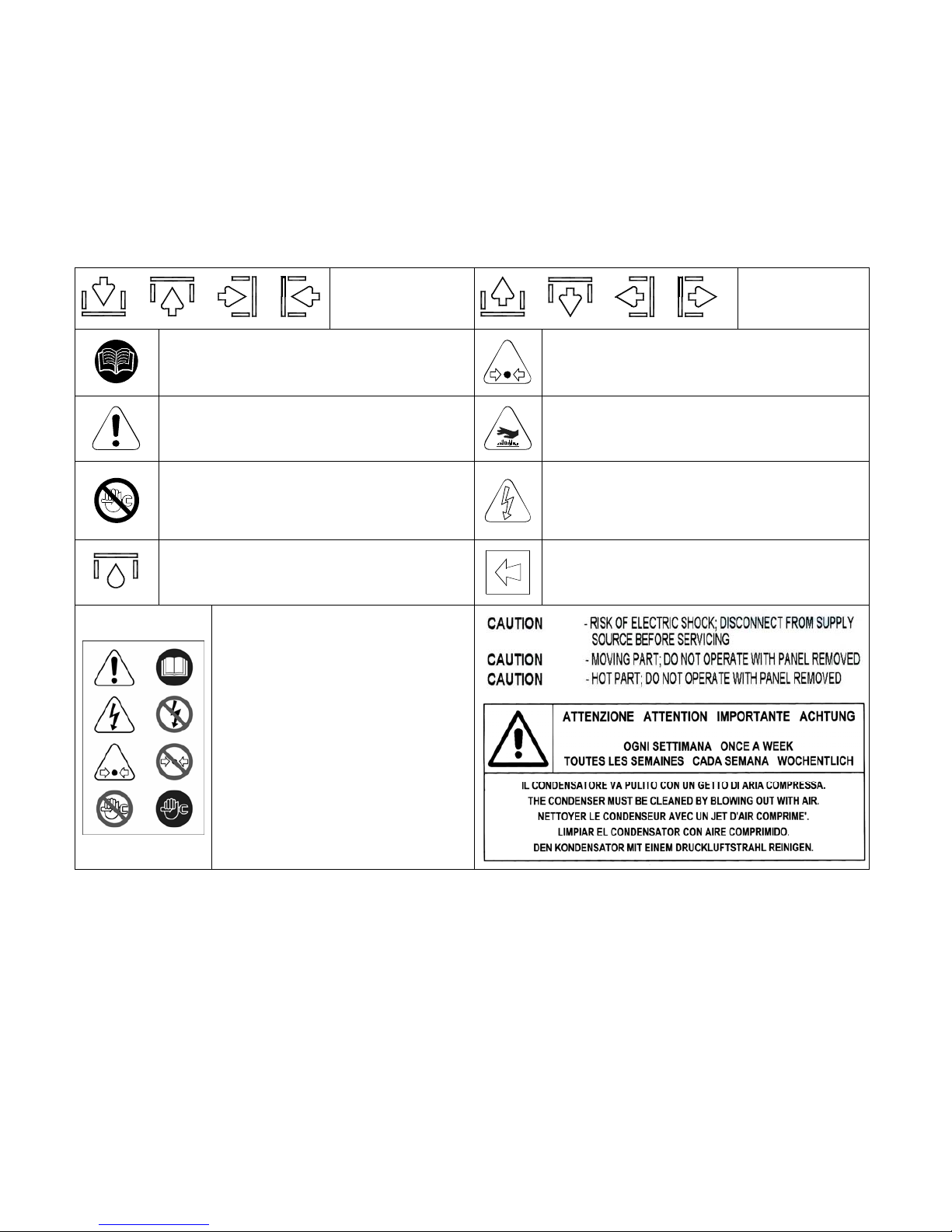
SYMBOLS AND LABELS USED IN THE MANUAL AND ON THE DRYER
or or or
Air inlet.
or or or
Air outlet.
Read the Operators manual before attempt to
start up the machine and to perform any
service operation on the dryer.
Pay particular attention to components or
systems under pressure.
Pay particular attention to the indications
preceded by these symbols.
Pay particular attention to hot surfaces.
Installation, maintenance, and/or control
operations preceded by these symbols must
be performed exclusively by qualified
personnel*.
Pay particular attention to the risk of electric
shock.
Condensate drain point.
Rotation direction of the fan.
Attention: Before performing any
maintenance operation on this
machine, do not forget to disconnect
the electric supply, to completely
discharge air pressure, and to refer to
the Operators manual
* Qualified personnel must be trained and certified in accordance with local laws and regulations.
WARRANTY
The Company warrants that the equipment manufactured by it and delivered hereunder will be free of defects in material and
workmanship for a period of twelve months from the date of placing the Equipment in operation or eighteen months from the
date of shipment from the factory, whichever shall first occur. The Purchaser shall be obligated to promptly report any failure to
conform to this warranty, in writing to the Company in said period, whereupon the Company shall, at its option, correct such
nonconformity, by suitable repair to such equipment or, furnish a replacement part F.O.B. point of shipment, provided the
Purchaser has stored, installed, maintained and operated such Equipment in accordance with good industry practices and has
complied with specific recommendations of the Company. Accessories or equipment furnished by the Company, but
manufactured by others, shall carry whatever warranty the manufacturers have conveyed to the Company and which can be
passed on to the Purchaser. The Company shall not be liable for any repairs, replacements, or adjustments to the Equipment or
any costs of labor performed by the Purchaser or others without Company's prior written approval.
The effects of corrosion, erosion and normal wear and tear are specifically excluded. Performance warranties are limited to
those specifically stated within the Company's proposal. Unless responsibility for meeting such performance warranties are
limited to specified tests, the Company's obligation shall be to correct in the manner and for the period of time provided above.
THE COMPANY MAKES NO OTHER WARRANTY OR REPRESENTATION OF ANY KIND WHATSOEVER, EXPRESSED
OR IMPLIED, EXCEPT THAT OF TITLE, AND ALL IMPLIED WARRANTIES OF MERCHANTABILITY AND FITNESS FOR A
PARTICULAR PURPOSE, ARE HERBY DISCLAIMED.
Cod. 710.0138.39.00 Rev1A – 05.2008 2 - 28
Page 4

Correction by the Company of nonconformities whether patent or latent, in the manner and for the period of time provided
above, shall constitute fulfillment of all liabilities of the Company for such nonconformities whether based on contract, warranty
negligence, indemnity, strict liability or otherwise with respect to or arising out of such Equipment.
The Purchaser shall not operate Equipment which is considered to be defective, without first notifying the Company in writing
of its intention to do so. Any such use of Equipment will be at Purchaser's sole risk and liability.
Note that this is Ingersoll Rand standard warranty. Any warranty in force at the time of purchase of the equipment or
negotiated as part of the purchase order may take precedence over this warranty.
1. GENERAL INFORMATION
1.1 FUNCTIONAL DESCRIPTION
Ingersoll Rand refrigerated air dryers remove moisture from compressed air. Moisture is detrimental to pneumatically
operated appliances, controls, instruments, machinery and tools.
Compressed air enters the patented aluminum heat exchanger where it is cooled down to the dew point temperature in
two different stages: In the first air/air sector compressed inlet air is cooled thanks to the colder compressed air coming
out counterflow from the condensate separator. In the second refrigerant / air sector, compressed air temperature is
further lowered to the dew point temperature. During this two stages almost all the oil and water vapours contained in
compressed air are condensed to liquid and successively be separated from the compressed air in the condensate
separator and drained out by the automatic drain. At this point the obtained cold air re-enters counterflow the initial air / air
exchanger and it is reheated by the inlet hot air with the consequence of energy recovering and also reduction of the
relative humidity contained in the outflowing air.
This dryer can be easily installed into various pneumatic systems in which dry air is required or desired. Please refer to
Start up chapter for complete operating details.
The dryer comes provided with all the control, safety and adjustment devices, therefore no auxiliary devices
are needed.
A system overload not exceeding the maximum operative limits can worsen the operational performance of the
dryer (high dew point), but it will not affect its safety.
The electric diagram (attachment B) shows the minimum protection degree IP 42.
Improper grounding can result in electrical shock and can cause severe injury or death.
This product must be connected to a grounded, metallic, permanent wiring system or an equipment-grounding
terminal or lead on the product.
All grounding must be performed by a qualified electrician and comply with national and local electrical codes.
In the event of an electrical short circuit, grounding reduces the risk of electric shock by providing an escape
wire for the electric current.
Ground must be established with a bare grounding wire sized according to the voltage and minimum branch
circuit requirements.
Ensure good bare metal contact at all grounding connection points, and ensure all connections are clean and
tight.
Check grounding connections after initial installation and periodically thereafter to ensure good contact and
continuity has been maintained.
Check with a qualified electrician or service technician if the grounding instructions are not completely
understood, or if in doubt as to whether the product is properly grounded.
1.2 USE OF THE MACHINE IN SAFE CONDITIONS
This system has been designed and manufactured in compliance with the European safety directive in force and
UL/ULC, therefore any installation, use and maintenance operations must be performed respecting the instructions
contained in this manual.
Because an air dryer is pressurized and contains rotating parts, the same precautions should be observed as with any
piece of machinery of this type where carelessness in operation or maintenance could be hazardous to personnel. In
addition to obvious safety rules that should be followed with this type of machinery, safety precautions as listed below
must be observed.
1. Only qualified personnel shall be permitted to adjust, perform maintenance or repair this air dryer.
2. Read all instructions completely before operating unit.
3. Pull main electrical disconnect switch and disconnect any separate control lines, if used, before
attempting to work or perform maintenance on the unit.
4. Do not attempt to service any part while machine is in an operational mode.
5. Do not attempt to remove any parts without first relieving the entire air system of pressure.
6. Do not attempt to remove any part of the refrigeration system without removing and containing
refrigerant in accordance with the EPA and local regulations.
7. Do not operate the dryer at pressures in excess of its rating.
8. Do not operate the dryer without guards, shields and screen in place.
9. Inspect unit daily to observe and correct any unsafe operating conditions.
Cod. 710.0138.39.00 Rev1A – 05.2008 3 - 28
Page 5
2. INSTALLATION
2.1 ACCEPTANCE, UNPACKING AND HANDLING
Upon receiving your Ingersoll Rand air dryer, please inspect the unit closely. If rough handling is detected, please note
it on your delivery receipt, especially if the dryer will not be uncrated immediately. Obtaining the delivery person's signed
agreement to any noted damages will facilitate any insurance claims by the customer.
It is mandatory to keep the dryer always in vertical position, as indicated by the symbols present on the packaging. For
handling, use devices having sufficient capacity for the weight of the machine.
Remove the packaging after having positioned the dryer in the installation site. Dispose the various packaging
materials in compliance with the relevant rules locally in force.
If not in use, the dryer can be stored in its packaging in a dust free and protected site between 32°F (0°C) and 120 °F
(50 °C), and a specific humidity not exceeding 90 %. Should the stocking time exceed 12 months, please contact your
local Ingersoll Rand authorized distributor.
Under no circumstances should any person attempt to lift heavy objects without proper lifting equipment (i.e., crane,
hoist, slings or fork truck). Lifting any unit without proper lifting equipment, may cause serious injury. Use fork lift channels
where provided.
2.2 INSTALLATION SITE
While preparing a proper site for the installation of the dryer, please take into account the following
requirements
The machine must be protected from atmospheric agents and not directly exposed to sun light.
A seating base flat and capable to hold the weight of the machine.
Ambient temperature complying with the nominal data of the dryer.
The dryer should be located in a clean area, without forced air draft that can affect the fan control
system.
Make sure to leave sufficient clearance (20 inches, 500 mm) around the dryer in order to allow an
adequate cooling of the machine and for maintenance and/or control operations.
The incoming air must be free from smoke or flammable vapours which could lead to explosion or fire risks.
2.3 INSTALLATION
Before attempting any installation operation, make sure that
No parts of the air system are under pressure.
No parts of the system are electrically powered.
Tubing to be connected to the dryer are free of impurities.
All interconnecting piping has been tightened.
After having verified the points listed above, you can proceed to the installation of the machine.
1. Connect the dryer to the compressed air lines. If not already existing, we suggest to install a by-pass
allowing to isolate the machine from the plant, thus to facilitate eventual maintenance operations.
2. Perform the electrical connection in accordance with any local laws and regulations after reviewing
the dryer electrical specifications and wiring diagram.
3. Check the condensate drainage assembly, and connect the drain flexible hose to the draining line,
keeping in mind that the condensate separated by the dryer may contain oil, therefore, in order
to dispose of it in compliance with the local rules in force, we suggest installing a water-oil
separator having adequate capacity.
4. Power the dryer after having checked that the nominal voltage and line frequency are constant and
matching the nominal values of the machine. The user must provide the installation with an
adequate line protection and a ground terminal complying with the electrical rules locally in
force.
In order to optimise the use of the dryer, we suggest to place it in such a way that all the control instruments
of the machine will result easily visible.
A suitably sized prefilter must be installed before the dryer. Failure to install and maintain a proper
prefilter will void the dryer warranty. The rating for this filter must be at least 10 micron.
Cod. 710.0138.39.00 Rev1A – 05.2008 4 - 28
Page 6
3. START UP
Ensure that the dryer is by−passed, or there is no load on the cooler.
Switch on the main electrical isolation switch (if present). The control panel will show the message OFF, indicating that the
line and control voltages are available.
Start sequence
The dryer will initially start by pressing the local ON/OFF button for 1 second. The start sequence will progress only if there
are no active alarms. The compressor motor will start AFTER 120 SECONDS. The fan motor will start simultaneously with
the compressor for D300-360IN models, after 30 seconds for smaller models.
Stop sequence
The dryer can be stopped locally from the control panel. After having pressed the ON/OFF switch for 1 second, the
compressor and the fan motor keep on running for further 10 seconds in order to re-balance the internal pressures. The
dryer can be also stopped due to an alarm or energy saving condition (ESA or ES2). Any alarm will de−energize the
compressor, fan motor can still running, it depends on the type of alarm (see Display indications chapter). If the shutdown is
due to an alarm, a message will blink on display indicating the reason for the shutdown. Energy saving condition (ESA or
ES2) occurs when the dew point stands below the set value for a long time in order to save energy and avoid heat
exchanger freezing. This situation can happen when ambient temperature is low and there is no compressed air load.
Variable speed fan control
A patented microprocessor allows to adjust dryer’s cooling capacity by changing the fan motor speed. If the dew point is
greater than the set value, the fan speed is increased, if the dew point is smaller than the set value, the fan velocity is
decreased. The range can be from 0 to 100% and the higher is the fan speed, the faster the fan LED blinks, you can read
the exact value by pressing the UP button. If the velocity is 100% you will read FL (Full Load). Under load standard
condition the fan speed is usually at 100%, if there is no load the fan velocity can oscillate between 0 and 20%.
In models D300-360IN, in order to adjust the greater dryer’s cooling capacity, a hot gas by-pass valve cooperates with the
variable speed system.
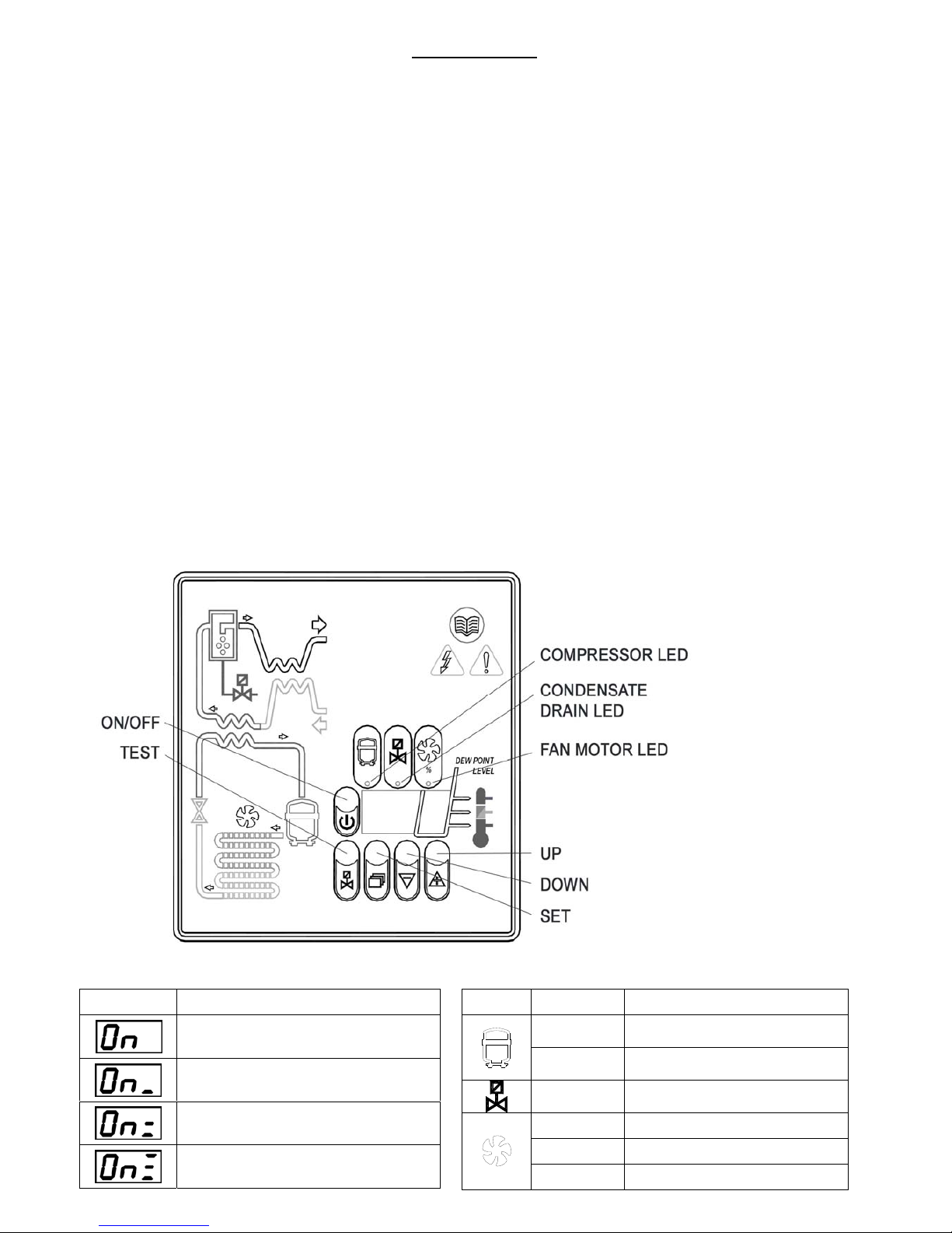
3.1 CONTROL PANEL
The dryers are provided with an electronic control system. All adjustments and resets can be performed by means of the
digital panel located on the front of the dryer.
The control panel is composed of 5 keys (ON/OFF, TEST, SET, DOWN and UP) and a 3 digit display, with three
signalling LEDs indicated by icons (PIC 1)
PIC. 1
DISPLAY VISUALIZATION AND SIGNALLING LEDS
DISPLAY DESCRIPTION
the unit is ON with low load
the unit is ON with normal load
the unit is ON with normal-high load
the unit is ON with high load
LED STATUS DESCRIPTION
ON
Compressor energized
Blinking
Programming mode activated
ON
Condensate drain energized
ON
Speed of the fan = 100%
Blinking
Speed of the fan < 100%
OFF
Fan not running
Cod. 710.0138.39.00 Rev1A – 05.2008 5 - 28
Page 7
3.1.1 KEYS FUNCTION
TEST: When pushed for 3 sec. during normal operation, it activates the condensate drain.
SET: When pushed and released during normal operation, it displays the dew point set value (decimal).
When pushed for 10 seconds, it allows to enter the C8 and C9 condensate drain parameters programming
menu (see relevant table).
When pushed after having set new configuration values, it stores the applied modifications.
DOWN: When pushed while setting the drain set point, it decreases the displayed value of one unit per
second, during the first 10 seconds, than of one unit every 0,1 sec.
When pushed for 10 seconds during normal operation, it starts an automatic test cycle of the controller.
UP: When pushed while setting the drain set point, it increases the displayed value of one unit per second,
during the first 10 seconds, than of one unit every 0,1 sec.
ON / OFF: Pushed for 1 second, it activates or deactivates the dryer. When the dryer is deactivated, the
display shows OFF.
NOTE: when the controller is in the OFF position, some parts of the dryer may still be energized. Therefore, for
safety purposes, disconnect the electrical power before performing any operation on the machine.
3.1.2 CONDENSATE DISCHARGE PARAMETERS PROGRAMMING
Push the SET key for 10 seconds to enter the parameters configuration menu: the display will show in
sequence the set point value, the code of the first modifiable parameter (C8) and its value).
Only if strictly necessary, use the UP and/or DOWN keys to change the displayed parameter value.
Press the SET key to store the previously changed parameter value or to browse the parameters without
changing them.
15 seconds after the last performed operation, the controller will return automatically to the normal
operation mode.
PARAMETER DESCRIPTION RANGE DEFAULT SET VALUE
C8
Delay between condensate
discharges
1 ÷ 999 (min)
1
D12-144IN D180IN D300-360IN
C9
Time required for condensate
discharge
1 ÷ 999 (sec)
1 2 3
NOTE: Changes entered for timing values will be effective only after exiting the programming, while changes to
other variables will be immediately effective.
Please remember that eventual changes to the configuration parameters of the machine could negatively affect
its efficiency. Thus, changes have to be performed by a person familiar with the operation of the dryer.
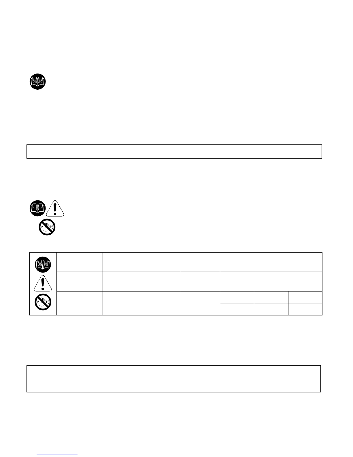
WARNING FOR USER:
IT’S FORBIDDEN TO ATTEMPT TO MODIFY THE OTHER CONFIGURATION PARAMETERS OF THE
ELECTRONIC CONTROLLER WITHOUT AUTHORIZATION AND COLLABORATION OF INGERSOLL RAND’S
AUTHORIZED DISTRIBUTOR.
Cod. 710.0138.39.00 Rev1A – 05.2008 6 - 28
Page 8
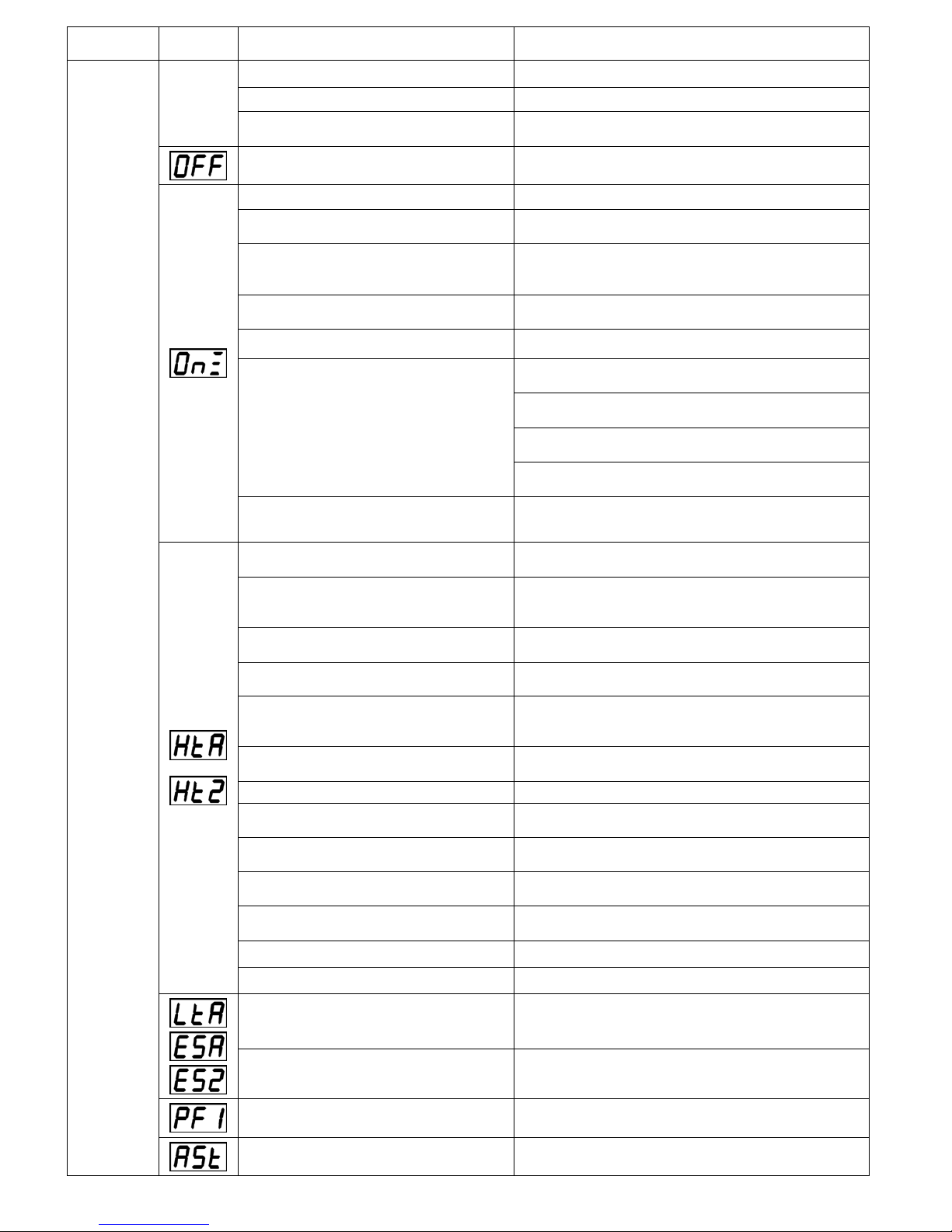
3.1.3 DISPLAY INDICATIONS
The controller is capable of recognizing certain types of anomalies in the drying circuit. In such cases, a message will
blink on the display, alternated to the current dew point value.
MESSAGE
(BLINKING)
CAUSE OUTPUTS ACTIONS
HtA
High dew point value
(delayed alarm)
Ht2
Very high dew point value
(immediate alarm)
Alarm output ON
Refrig. Compressor output OFF
Fan output ON
Drain cycle standard
Resettable by switching off the
dryer.
If problem persists call your
local Ingersoll Rand distributor.
LtA
Low dew point value
Alarm output ON
Refrig. Compressor output OFF
Fan output OFF
Drain cycle standard
Automatic reset when dew
point returns to preset range.
If problem persists call your
local Ingersoll Rand distributor.
PF1
Interruption or short circuit on
the PTC probe input line
Alarm output ON
Refrig. Compressor output OFF
Fan output OFF
Drain cycle standard
Resettable by switching off the
dryer. May require replacing the
faulty probe.
If problem persists call your
local Ingersoll Rand distributor.
ESA
ES2
The automatic Energy saving
mode activated due to low
load
Alarm output OFF
Refrig. Compressor output OFF
Fan output OFF
Drain cycle standard
No action necessary.
Automatic Reset
ASt
Activated after repeated
alarms
Alarm output ON
Refrig. Compressor output OFF
Fan output ON
Drain cycle standard
Call your local Ingersoll Rand
distributor.
Note: PF1 has priority on all other messages.
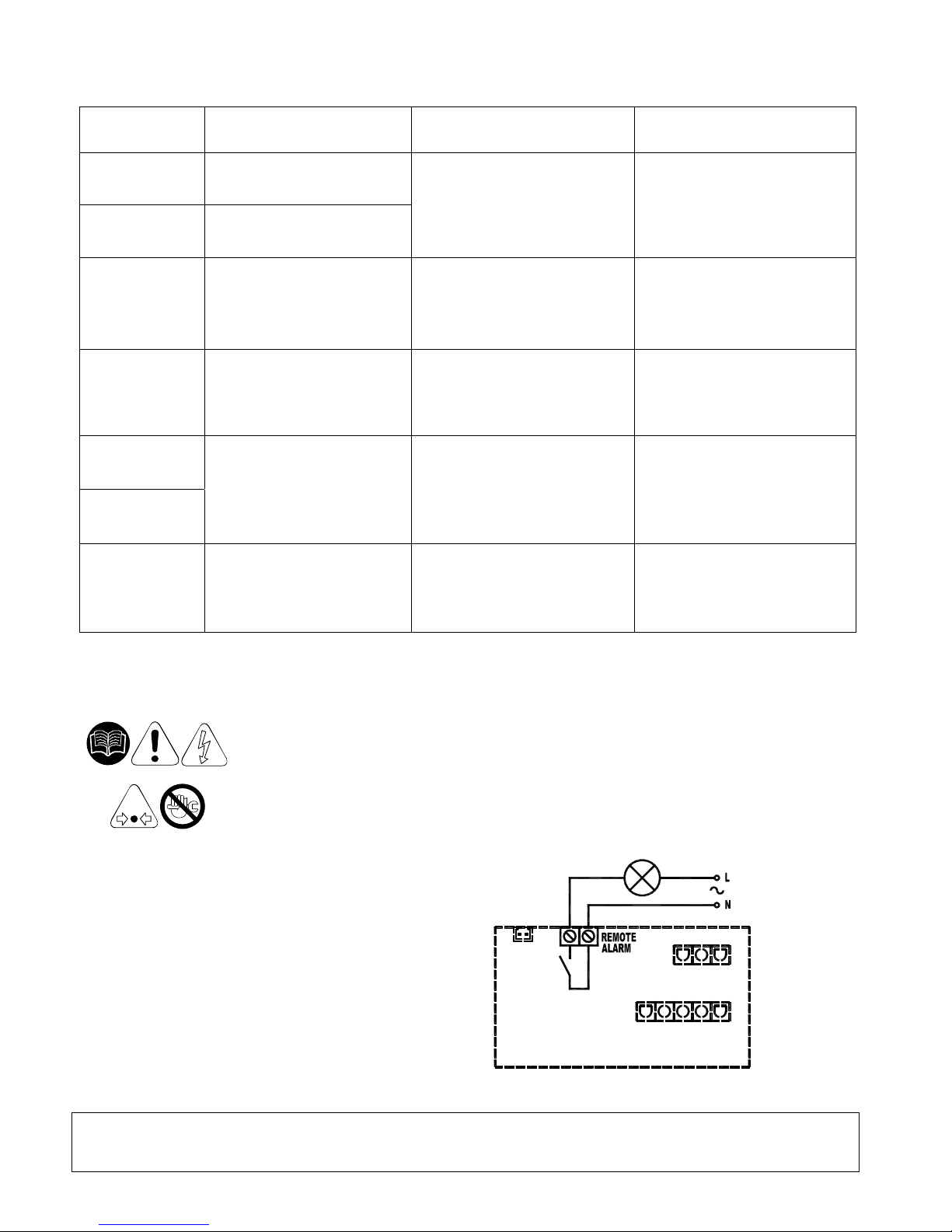
3.1.4 REMOTE SIGNALING ALARM
The dryer control board is equipped with a dry contact for a remote alarm signal. This is
normally open contact: when an alarm is detected, this contact is closed.
Proceed as follows to activate a remote alarm output:
1. The User must review the diagram below.
2. Disconnect the dryer from electrical power supply, remove cover and left side panel.
3. Connect the alarm circuit to the terminal blocks (See PIC.2).
4. Replace cover, left side panel and reconnect power.
Alarm Output relays electric
features:
Max. 250VAC / 3A – AC 15 (Amp. Inductive)
PIC.2
The activation of the above function is at the User’s discretion. The User will purchase all necessary
installation material. Any operation which needs access to the dryer must be carried out by qualified
personnel.
Cod. 710.0138.39.00 Rev1A – 05.2008 7 - 28
Page 9
3.2 BEFORE START UP
Before starting the machine, make sure that all operating parameters correspond to the nominal data.
The dryer is supplied already tested and preset for normal operation, and it doesn’t require any calibration.
Nevertheless, it’s necessary to check the operating performances during the first working hours.
3.3 START UP
The operations specified below must be performed after the first start up and at each start up after a
prolonged inactive period of time due to maintenance operations, or any other reason.
1. Make sure that all instructions contained in chapters INSTALLATION SITE and INSTALLATION
have been observed.
2. Ensure dryer by-pass is open and air inlet/outlet valves closed. (if existing).
3. Activate power supply and press the ON/OFF switch on the control panel for at least 1 second.
(note there is a 2 minute delay before the dryer will start after the dryer is turned on).
4. Wait 5 to 10 minutes until machine has achieved its standard operating parameters.
5. Slowly open the air outlet valve and successively open the air inlet valve.
6. If existent, close the air by-pass valve.
7. Check if the condensate drain is working properly.
8. Check if all connecting pipes are properly tightened and fixed.
Before disconnecting the dryer from electrical power supply, use ON/OFF switch to stop the
dryer. Otherwise wait 10 minutes before switching the dryer on again, in order to allow freon
pressure to rebalance.
4. MAINTENANCE, TROUBLESHOOTING AND DECOMMISSIONING
4.1 MAINTENANCE
Before attempting any maintenance operation, make sure that:
1. No parts of the system are under pressure.
2. No parts of the system are electrically powered.
Î WEEKLY OR EVERY 40 HOURS OF OPERATION
Verify the temperature on the control panel display is acceptable.
Visually check if the condensate is drained regularly.
Î MONTHLY OR EVERY 200 HOURS OF OPERATION
Clean the condenser with compressed air, taking care not to damage the condenser fins..
At the end of the above mentioned operations, check if the dryer is working properly.
Check the condition of any filters installed with the dryer. Replace elements as needed.
Î YEARLY OR EVERY 2000 HOURS OF OPERATION
Check if the flexible tube used for condensate drainage is damaged and replace it if necessary.
Check if all connecting pipes are properly tightened and fixed.
At the end of the above mentioned operations, check if the dryer is working properly.
4.2 TROUBLESHOOTING
NOTE: FOLLOWING BEHAVIORS ARE NORMAL CHARACTERISTIC OF OPERATION AND NOT TROUBLES
• Variable speed of the fan.
• Display of message ESA and ES2 in case of operation without load or low load.
• A 2 minute delay for dryer to start after pressing the on/off switch.
Troubleshooting and eventual control and/or maintenance operations must be performed
by qualified personnel.
For maintaining the refrigerating circuit of the machine, contact a refrigeration engineer.
Cod. 710.0138.39.00 Rev1A – 05.2008 8 - 28
Page 10
TROUBLE DISPLAY POSSIBLE CAUSE REMEDY
No power in the line. Restore the power in the line.
Problems with cabling. Check cabling; if the trouble persists, replace it.
Control
panel
display is
blank
Problems with the electronic control
board.
Check the electronic control board; if the trouble
persists, replace it.
The dryer is off.
Turn it on by pressing the ON/OFF switch for 1
second.
Dryer in stand-by. Wait 2 minutes after the dryer is switched on.
Compressed air inlet/outlet inverted.
Check if the compressed air inlet/outlet is connected
properly.
The flow rate and/or temperature of the
air entering the dryer are higher than the
nominal values.
Restore the nominal conditions.
The ambient temperature is higher than
the nominal values.
Restore the nominal conditions.
The condenser is dirty. Clean the condenser.
Clean the condensate drainage system pre-filter.
(Pic.3)
Replace the coil of the drainage solenoid valve if
burned.
Clean or replace the drainage solenoid valve if
clogged/jammed.
Condensate drain is not functioning.
Check the C8 and C9 parameters of the electronic
control board; if the trouble persists, replace it.
The temperature control probe is
positioned improperly or faulty.
Check the probe; if the trouble persists, replace it.
Problems with cabling or with the
electronic control board.
Check the cabling and the electronic control board, if
the trouble persists, replace them.
Activation of compressor’s internal
thermal protection.
Wait one hour and check again. If the fault persists:
stop dryer and call your local Ingersoll Rand
distributor.
Problems with the electrical components
of the compressor.
Check the electrical components of the compressor.
Defective compressor. Replace the compressor.
The flow rate and/or temperature of the
air entering the dryer are higher than the
nominal values.
Restore the nominal conditions.
The ambient temperature is higher than
the nominal values.
Restore the nominal conditions.
The condenser is dirty. Clean the condenser.
The temperature control probe is
positioned improperly or faulty.
Check the probe; if the trouble persists, replace it.
Fan pressure switch defective or burned
out (if present).
Turn off the dryer and call your local Ingersoll Rand
distributor.
High pressure switch defective or burned
out (if present).
Turn off the dryer and call your local Ingersoll Rand
distributor.
Gas leakage in the refrigerating circuit.
Turn off the dryer and call your local Ingersoll Rand
distributor.
Defective fan. Replace the fan.
Protection fuse burned out (if present). Replace the fuse.
The temperature control probe is
positioned improperly or faulty.
Check the probe; if the trouble persists, replace it.
Gas leakage in the refrigerating circuit
without load.
Turn off the dryer and call your local Ingersoll Rand
distributor.
The temperature control probe is
positioned improperly or faulty.
Check the probe; if the trouble persists, replace it.
WATER IN THE SYSTEM
Series of alarms very close to each
other.
Call your local Ingersoll Rand distributor.
Cod. 710.0138.39.00 Rev1A – 05.2008 9 - 28
Page 11

Check the probe; if the trouble persists, replace it.
Check the electronic control board; if the trouble
persists, replace it.
Ice formation in the evaporator.
Contact our Service Centre to check the gas charge.
Check if the compressed air inlet/outlet is connected
properly.
Check if the connecting tubing is clogged; in case
proceed accordingly.
Check if any valves are closed.
Clog.
Check the condition of any filter.
Drainage solenoid valve jammed, clean or replace it.
Verify the condensate drainage times set on the
electronic control board (C8 and C9).
LOW PRESSURE IN THE LINE
Air flows continuously through the
condensate drainage.
Check the signal from the control board: if it is
continuous, replace the control board.
TROUBLE DISPLAY POSSIBLE CAUSE REMEDY
IMPORTANT:
The temperature control probe is extremely delicate. Do not remove the probe from its position. In case
of any kind of problem, please contact your local Ingersoll Rand distributor
Pic.3
4.3 DECOMMISSIONING
In case of necessity, decommission the machine and the relevant packaging in compliance with the
rules locally in force.
Pay particular attention to the refrigerant, as it contains part of the refrigerating compressor lubricating
oil.
Always contact a waste disposal and recycling facility.
Cod. 710.0138.39.00 Rev1A – 05.2008 10 - 28
Page 12

- FR -
PREAMBULE
Le présent manuel fait partie intégrante du séchoir que vous venez d'acheter et doit toujours accompagner la machine,
même en cas de revente de cette dernière.
Il est indispensable que le personnel spécialisé* chargé des opérations d'installation, d'entretien et/ou de contrôle observe
scrupuleusement les consignes données dans ce manuel ainsi que les normes de prévention et de sécurité en vigueur dans le
pays d'utilisation. Telles sont les conditions pour un usage rationnel et une exploitation rentable de la machine.
En cas de problème avec votre séchoir, n'hésitez pas à consulter votre revendeur Ingersoll Rand local autorisé.
En cas de nécessité, à noter que l'utilisation de pièces détachées originales garantit l'efficacité et la longévité de votre
séchoir.
En raison de l'évolution constante sur le plan technique, Ingersoll Rand se réserve le droit de modifier sans préavis les
spécifications figurant dans le présent manuel.
SYMBOLES UTILISES DANS LE MANUEL ET SUR LE SECHOIR
ou ou ou
Point d'entrée
de l'air.
ou ou ou
Point de sortie
de l'air.
Lire le manuel des opérateurs avant la mise
en service et avant toute intervention sur la
machine.
Faire particulièrement attention: composant ou
installation sous pression.
Faire particulièrement attention aux
indications précédées par ce symbole.
Faire particulièrement attention: surface chaude.
Les opérations d’installation, d'entretien
et/ou de contrôle précédées par ce symbole
doivent être effectuées exclusivement par du
personnel spécialisé*.
Faire particulièrement attention: risque de
décharge électrique.
Point d'évacuation des condensants.
Sens de rotation du moteur du ventilateur.
Attention: n'effectuer aucune
opération d'entretien sur cette
machine sans avoir coupé
l'alimentation électrique, avoir purgé
complètement l'air sous pression et
consulté le manuel des opérateurs.
* Le personnel qualifié doit être formé et certifié conformément aux lois et aux règlements locaux.
GARANTIE
La société garantit que l’équipement qu’elle fabrique et qui est fourni ici est exempt de défauts matériels et de maind’œuvre pour une durée de douze mois à compter de la date de mise en service de l’équipement ou de dix-huit mois à
compter de la date d’expédition de l’usine, selon le premier terme arrivé à échéance. L’acheteur doit être obligé à signaler
rapidement toute non-conformité à cette garantie, en écrivant à la société dans le délai susmentionné, sur quoi la société devra,
à sa discrétion, corriger cette non-conformité en effectuant une réparation appropriée de cet équipement ou fournir une pièce de
rechange F.A.B. au point d’expédition, à condition que l’acheteur ait stocké, installé, entretenu et utilisé cet équipement
conformément aux bonnes pratiques du secteur et qu’il ait respecté les recommandations spécifiques de la société. Les
accessoires ou l’équipement fourni par la société, mais fabriqué par des tiers, doit reporter toutes les garanties que les
fabricants ont transmises à la société et qui peuvent être transmises à l’acheteur. La société ne peut être tenue responsable des
réparations, remplacements ou ajustement de l’équipement ou de tout coût de main-d’œuvre soutenu par l’acheteur ou des tiers
pour sans l’accord écrit préalable de la société.
Les effets de corrosion, érosion et l’usure normale sont spécifiquement exclus. Les garanties de performance se limitent à
celles spécifiquement mentionnées dans la proposition de la société. Les obligations de la société doivent être de corriger de la
façon et durant la période indiquée ci-dessus sauf si la responsabilité d’obtention de ces garanties de performance est limitée
aux tests spécifiés.
Cod. 710.0138.39.00 Rev1A – 05.2008 11 - 28
Page 13

LA SOCIÉTÉ N’ACCORDE AUCUNE AUTRE GARANTIE OU REPRÉSENTATION D’AUCUNE SORTE, EXPLICITE OU
IMPLICITE, A L’EXCEPTION DE LA GARANTIE EN OBJET ET TOUTES LES GARANTIES IMPLICITES DE QUALITÉ
MARCHANDE ET D’APTITUDE A UNE UTILISATION SPÉCIFIQUE, SONT PAR CONSÉQUENT REFUSÉES.
La correction par la société des non-conformités évidentes ou cachées, de la façon et pour la période de temps indiquées cidessus, doit constituer l’accomplissement de toutes les responsabilités de la société pour ces non-conformités qu’elles soient
basées sur contrat, négligence de garantie, indemnité, responsabilité stricte ou en rapport avec ou provenant de cet
équipement.
L’acheteur ne doit pas utiliser l’équipement s’il est considéré comme défectueux sans avoir préalablement averti la société
par écrit de sont intention. Une telle utilisation de l’équipement s’effectue sous la seule responsabilité de l’acheteur.
Veuillez noter qu’il s’agit d’une garantie standard d’Ingersoll Rand. Toute garantie en vigueur au moment de l’achat de
l’équipement ou négociée en tant que partie de l'achat possède la priorité sur cette garantie.
1. INFORMATIONS GENERALES
1.1 DESCRIPTION FONCTIONNELLE
Les séchoirs à air Ingersoll Rand éliminent l’humidité de l’air comprimé. L’humidité nuit aux appareils, commandes, instruments,
machines et outils à actionnement pneumatique.
L'air comprimé entre dans l'échangeur de chaleur breveté en aluminium dans lequel il est refroidi en deux étapes jusqu'à ce que
la température de l'air atteigne son point de condensation: dans le premier secteur air-air, l'air comprimé entrant est refroidi
grâce au contre-courant d'air froid comprimé provenant du séparateur de condensat. Dans le deuxième secteur air-air
réfrigérant, la température de l'air comprimé est de nouveau abaissée jusqu'à l'obtention de la température de point de
condensation. Durant ces deux étapes, la quasi totalité de la vapeur d'eau et d'huile contenue dans l'air comprimé s'est
condensée en liquide et a été ensuite séparée de l'air comprimé dans le séparateur de condensat pour enfin être rejetée par
l'évacuation automatique. A ce stade, l'air refroidi obtenu entre de nouveau à contre courant dans l'échangeur air-air initial et est
réchauffé par l'air chaud entrant, provoquant ainsi une récupération d'énergie et une réduction de l'humidité ambiante contenue
dans l'air sortant.
Ce séchoir peut être facilement installé dans différents systèmes pneumatiques qui nécessitent de l’air sec. Veuillez vous référer
aux principes de fonctionnement pour obtenir tous les détails sur le fonctionnement.
Le séchoir est déjà équipé de tous les dispositifs de contrôle, de sécurité et de réglage. Il n'a donc pas besoin de
dispositifs auxiliaires.
Une surcharge de l'installation dans les limites d'utilisation maximum entraîne une diminution des prestations du
séchoir (point de rosée élevé) mais ne nuit pas à la sécurité.
Le circuit électrique (annexe B) a un degré de protection minimum IP 42.
Merci de noter que une mise à terre incorrecte peut provoquer des chocs électriques et causer pourtant décès et
blessures graves.
Les séchoirs doivent être raccordés à un système de câblage à terre, en métal et permanent, ou au équipement des
bornes à terre, ou au conducteur isolé du séchoir..
Toutes opérations de mise à terre doivent être remplies par électriciens compétents conformément aux lois
nationaux et locales. Dans le cas de court-circuit, la mise à terre réduit le risqué de choc électrique permettant
l’échappement du courant.
La mise à terre doit être effectuée par câble dénudé à terre conformément aux voltage et qualités requise minimes
du branche du circuit.
S’assurer que les éléments métalliques dénudés soient raccordés aux points de mise à terre, vérifier que les
connexions soient propres et fermes.
Vérifier les connexions à terre après la première installation et effectuer les vérifications périodiques à fin d’assurer
que le contact et la continuité soient gardés.
Si les indications de mise à terre ne sont pas claires ou s’il y a des doutes sur la propriété de la mise à terre du
produit, consulter un électricien compètent ou un technicien du service .
1.2 UTILISATION DU SECHOIR EN TOUTE SECURITE
Cette installation a été conçue et réalisée conformément aux directives européennes en vigueur. En conséquence de quoi,
toutes les opérations d'installation, d'utilisation et d'entretien doivent être effectuées conformément aux consignes données dans
le présent manuel.
Le séchoir d’air est sous pression et contient des pièces rotatives. Il faut donc prendre les mêmes précautions que pour une
machine du même genre pour laquelle une négligence lors de l’utilisation ou de l’entretien peut être dangereuse pour le
personnel. Les précautions de sécurité ci-dessous doivent être observées en plus des règles de sécurité évidentes qui doivent
être respectées avec ce type de machine.
1. Seul le personnel qualifié doit être autorisé à ajuster, effectuer l’entretien ou réparer ce séchoir d’air.
2. Lisez intégralement les instructions avant d’utiliser cet appareil.
3. Tirez l’interrupteur de déconnexion électrique et débranchez toutes les lignes de commande
séparées, le cas échéant, avant de travailler ou d’effectuer l’entretien sur l’appareil.
4. N’essayez jamais de réparer une pièce de la machine si cette dernière est en fonction.
5. N’essayez jamais de retirer une pièce sans avoir au préalable purgé l’air du système de pression.
6. N’essayez jamais de retirer une pièce du système de réfrigération sans avoir retiré et stocké le
frigorigène conformément aux règlements locaux et de l’APE.
7. N’utilisez pas le séchoir à une pression dépassant la pression nominale.
8. N’utilisez pas le séchoir si toutes les protections ne sont pas en place.
9. Inspectez l’appareil tous les jours afin de vérifier et de corriger toute condition de fonctionnement
dangereuse.
Cod. 710.0138.39.00 Rev1A – 05.2008 12 - 28
Page 14

2. INSTALLATION
2.1 RECEPTION ET TRANSPORT
Lors de la réception de votre séchoir d’air Ingersoll Rand, veuillez vérifier attentivement l’appareil. Si vous remarquez des
signes de manutention brusque, veuillez les noter sur le bordereau de livraison, en particulier si le séchoir n’est pas
déballé immédiatement. L’obtention de la signature du livreur pour convenir des dommages remarqués facilitera toute
demande d’assurance par le client.
Il est indispensable de maintenir le séchoir toujours en position verticale comme indiqué par les symboles sur l'emballage
et de le déplacer avec un dispositif ayant une portée suffisante pour le poids de la machine.
Déballer le séchoir après l'avoir déposé sur le lieu d'installation. Il est conseillé de conserver l'emballage original pendant
au moins toute la durée de la garantie de la machine ; A noter toutefois que l'élimination de chaque matériau d'emballage
doit être effectuée conformément à la réglementation en vigueur dans le pays d'utilisation.
Si le séchoir n'est utilisé pas dans l'immédiat, il peut être entreposé emballé dans un lieu fermé, non poussiéreux, à une
température entre 32°F et 120°F et une humidité inférieure à 90 %. Si le stockage doit durer pendant plus de 12 mois,
contacter votre revendeur Ingersoll Rand local autorisé.
Il ne faut en aucun cas tenter de soulever des objets lourds sans un équipement de levage approprié (grue, palan, élingue
ou chariot à fourches). Le levage de tout appareil sans un équipement de levage approprié peut entraîner de graves
blessures. Utilisez les glissières pour chariot à fourches le cas échéant.
2.2 LIEU D'INSTALLATION
Il est nécessaire de préparer le lieu d'installation du séchoir en tenant compte des critères suivants :
La machine devra être protégée contre les agents atmosphériques et contre la lumière directe du
soleil.
Base d'appui plat et en mesure de supporter le poids de la machine.
Température ambiante conforme aux données figurant sur la plaque du séchoir.
Le séchoir doit être placé dans un lieu propre, sans installation de ventilation forcée pouvant affecter
le système de commande du ventilateur.
Garantir suffisamment d'espace libre autour du séchoir (20 inches, 500 mm) pour permettre le
refroidissement correct de la machine et pour les opérations d'entretien et/ou de contrôle.
L’air aspiré doit être exempt de fumées ou de vapeurs inflammables susceptibles d'entraîner un risque
d'explosion ou d'incendie.
2.3 INSTALLATION
Avant toute opération d'installation, s'assurer que :
L’installation ne présente par de parties sous pression.
L’installation ne présente pas de parties sous tension.
Les conduites à raccorder le séchoir sont exemptes d'impuretés.
Toutes les tuyauteries raccordées ont été serrées.
Après avoir vérifié les points ci-dessus, il est possible de procéder à l'installation de la machine :
1. Raccorder le séchoir à la ligne d'air comprimé. L'installation d'un groupe by-pass est conseillée
(s'il est absent) car il permet d'isoler la machine de l'installation pour faciliter d'éventuelles
opérations d'entretien.
2. Effectuez les branchements électriques conformément aux lois et aux règlements locaux après
avoir consulté les spécifications électriques et le schéma de câblage du séchoir.
3. Vérifier le groupe de purge des condensants et raccorder le flexible d'évacuation à la ligne de
drainage en se rappelant du fait que les condensants séparés du séchoir contiennent des
particules d'huile ; Pour les éliminer conformément à la réglementation en vigueur dans le
pays d'utilisation, il est par conséquent conseillé d'installer un séparateur eau-huile d'une
capacité appropriée.
4. Alimenter le séchoir après s'être assuré que la tension de référence et la fréquence du réseau
électrique sont constantes et correspondent aux spécifications de référence de la machine. C'est
à l'utilisateur qu'il revient d'équiper l'installation d'un dispositif de protection de ligne et de
prise de terre conforme à la réglementation électrique en vigueur dans le pays d'utilisation.
Pour optimiser l'utilisation du séchoir, il est conseillé de l'orienter de façon à ce que tous les instruments
de contrôle de la machine soient facilement lisibles.
Un filtre correctement dimensionné doit être installé avant le séchoir. L’absence d’installation ou
d’entretien d’un filtre correct annule la garantie. Les mailles de ce filtre doivent être d’au moins 10 microns.
Cod. 710.0138.39.00 Rev1A – 05.2008 13 - 28
Page 15

3. MISE EN SERVICE
S'assurer que le sécheur est activé, et que le refroidisseur n'est pas en condition de travail.
Activer le commutateur sur la commande d'isolation électrique principale (si présent). Le panneau de commande affichera le message
OFF, indiquant que la tension de ligne et de contrôle est activée.
Séquence de démarrage
Le sécheur devra tout d'abord être mis en marche en pressant le bouton ON/OFF situé sur celui-ci pendant 1 seconde. La séquence de
démarrage ne continuera qu'en cas d'absence de toute alarme active. Le moteur du compresseur se mettra en marche APRES 120
SECONDES. Concernant les modèles D300-360IN, le moteur du ventilateur et le compresseur démarreront simultanément, alors qu'il
faudra compter 30 secondes entre les deux démarrages pour les plus petits modèles.
Séquence d'arrêt
Le sécheur peut être arrêté localement à partir du panneau de commande. Après avoir pressé le bouton ON/OFF pendant 1 seconde,
le compresseur et le moteur du ventilateur vont continuer à fonctionner pendant encore 10 secondes de façon à rééquilibrer la pression
interne. Le sécheur peut être également arrêté en raison d'une alarme ou d'une condition de conservation d'énergie (ESA ou ES2).
N'importe quelle alarme entraînera la coupure de l'alimentation électrique du compresseur, il est possible que le moteur du ventilateur
continue à fonctionner en fonction du type d'alarme (voir le Chapitre des indications de l'écran). Si l'interruption est due à une alarme, un
message clignotera sur l'écran en indiquant la raison de l'arrêt. Une condition de conservation d'énergie (ESA ou ES2) se produit lorsque
le point de condensation reste en dessous de la valeur de réglage pendant une longue période de façon à conserver l'énergie et à
éviter que l'échangeur de chaleur ne gèle. Cette situation peut survenir lorsque la température ambiante est basse et qu'il n'y a pas de
traitement d'air comprimé.
Commande de variation de vitesse du ventilateur
Un microprocesseur breveté permet d'ajuster la capacité de refroidissement du sécheur en variant la vitesse du moteur du ventilateur.
Si le point de condensation est plus élevé que la valeur de réglage, la vitesse de ventilation augmente, en revanche, si le point de
condensation est plus bas, la vitesse de ventilation diminue. Le niveau de vitesse peut aller de 0 à 100%, et la vitesse de clignotement
de la LED correspond à celle du ventilateur, il est possible de lire la valeur exacte en pressant le bouton HAUT. Si la vitesse est à
100%, le message FL ("Full Load", Pleine charge) s'affichera. En condition standard de travail, la vitesse de ventilation est
habituellement à 100%, en cas d'absence de travail, la vitesse de ventilation peut varier entre 0 et 20%. Dans les modèles D300-360IN,
une soupape de dérivation de gaz chaud fonctionne en collaboration avec le système de variation de vitesse.
3.1 PUPITRE DE COMMANDE
Les machines faisant partie de cette série sont équipées d'un système électronique de modification des paramètres ; Les éventuelles
opérations de réinitialisation peuvent en effet être effectuées à l'aide du pupitre numérique se trouvant sur la façade du séchoir.
Le pupitre de commande se compose de 5 touches (ON/OFF, TEST, SET, DOWN et UP) et par un afficheur à 3 chiffres avec trois
diodes électroluminescentes de signalisation indiquées par icônes (Fig. 1)
Le bon fonctionnement de la machine peut être contrôlé à l'aide du pupitre de commande illustré ci-dessous.
Fig. 1
ECRAN D AFFICHAGE ET DIODES ELECTROLUMINESCENTES DE SIGNALISATION
DISPLAY DESCRIPTION
Indique que le sécheur est en marche à
faible charge
Indique que le sécheur est en marche à
charge normale
Indique que l le sécheur est en marche à
charge moyenne;
Indique que le sécheur est en marche à
pleine charge
LED STATUS DESCRIPTION
Allumée
Compresseur active
Clignotant
Modalité programmation
Allumée
Purge de condesants active
Allumée
Vitesse ventilateur = 100%
Clignotant
Vitesse ventilateur < 100%
Eteint
Ventilateur ne pas courir
Cod. 710.0138.39.00 Rev1A – 05.2008 14 - 28
Page 16

3.1.1 FONCTION DES TOUCHES
TEST: Lorsqu'on appuie dessus pendant 3 secondes lors du fonctionnement normal, elle permet d'activer un
cycle de purge des condensants.
SET: Si l'on appuie dessus pendant le fonctionnement normal, elle affiche la valeur du point de consigne.
Maintenu sous pression pendant 10 secondes, elle permet l'accès au menu de programmation des paramètres
(Voir le tableau correspondant).
Si l'on appuie dessus après avoir programmé de nouvelles valeurs de configuration et du point de consigne, elle
mémorise les variations apportées.
DOWN: Si l'on appuie dessus pendant le paramétrage du point de consigne ou des paramètres de
configuration, elle diminue la valeur affichée sur l'afficheur d'une unité par seconde, pendant les 10 premières
secondes de pression, et ensuite d'une unité toutes les 0,1 secondes.
Si l'on appuie dessus pendant 10 secondes pendant le fonctionnement normal, elle fait démarrer le cycle de test
automatique du contrôleur.
UP: Si l'on appuie dessus pendant le paramétrage du point de consigne ou des paramètres de configuration,
elle augmente la valeur affichée sur l'afficheur d'une unité par seconde, pendant les 10 premières secondes de
pression, et ensuite d'une unité toutes les 0,1 secondes.
ON / OFF: Appuyer sur la touche pendant 1 seconde active ou désactive le processus. Lorsque le processus est
désactivé, l'afficheur affiche le message OFF.
ATTENTION: lorsque la carte électronique indique OFF, plusieurs composants du sécheur reste sous tension.
Donc, pour des raisons de sécurité, il est impératif de couper l'alimentation électrique du sécheur avant toute
opération sur celui-ci.
3.1.2 CONTROLE ET MODIFICATION DES PARAMETRES DE CONFIGURATION
Appuyer sur SET pendant 10 secondes pour l'entrée dans le menu de programmation des
paramètres : l'afficheur affiche dans l'ordre la valeur du point de consigne, le code du premier
paramètre modifiable E1 et sa valeur.
Utiliser les touches UP et/ou DOWN pour modifier, seulement si cela est strictement nécessaire, la
valeur du paramètre affiché.
Appuyer sur la touche SET pour mémoriser la valeur du paramètre préalablement modifié ou pour
faire défiler les paramètres sans les modifier.
Passé un laps de temps de 15 secondes après la dernière opération effectuée, le contrôleur se
remet automatiquement en mode de fonctionnement normal.
PARAMETRE DESCRIPTION PLAGE VALEUR REGLEE
C8
Retard entre les purges de
condensants
1 ÷ 999 (min)
1
D12-144IN D180IN D300-360IN
C9
Durée de purge des
condensants
1 ÷ 999 (sec)
1 2 3
AVERTISSEMENT POUR L’UTILISATEUR :
IL EST INTERDIT DE MODIFIER LES PARAMETRES DE CONFIGURATION RESTANTS DU CONTROLEUR
ELECTRONIQUE SANS L'AUTORISATION DU FOURNISSEUR.
Cod. 710.0138.39.00 Rev1A – 05.2008 15 - 28
Page 17

3.1.3 SIGNALISATION D'ANOMALIES
Le contrôleur est en mesure de reconnaître des types d’anomalies déterminés du circuit de séchage qui entraîne
l’affichage d’un message d’alarme clignotant sur l’écran alterné à la valeur courante du point de condensation.
MESSAGE
(CLIGNOTANT)
CAUSE SORTIES ACTIONS
HtA
Point de condensation élevé
(alarme retardée)
Ht2
Point de condensation très
élevé
(alarme immédiate)
Sortie alarme active
Sortie compresseur inactive
Sortie ventilateur active
Sortie évacuation standard
Réinitialisation par extinction de la
centrale lorsque le point de
condensation rentre dans la plage
préprogrammée.
Si le problème persiste, contacter
votre revendeur Ingersoll Rand local
autorisé.
LtA
Point de condensation bas
Sortie alarme active
Sortie compresseur inactive
Sortie ventilateur inactive
Sortie évacuation standard
Réinitialisation automatique si le point
de condensation rentre dans la plage
préprogrammée.
Si le problème persiste, contacter
votre revendeur Ingersoll Rand local
autorisé.
PF1
Interruption ou court-circuit
de la ligne d’entrée de la
sonde PTC
Sortie alarme active
Sortie compresseur inactive
Sortie ventilateur inactive
Sortie évacuation standard
Réinitialisation après remplacement
de la sonde et extinction de la
centrale.
Contacter le votre revendeur Ingersoll
Rand local autorisé.
ESA
ES2
Option d’économie d’énergie
active
Sortie alarme active
Sortie compresseur inactive
Sortie ventilateur inactive
Sortie évacuation standard
Aucune réinitialisation automatique.
ASt
Série d'alarme proche les
unes des autres
Sortie alarme active
Sortie compresseur inactive
Sortie ventilateur active
Sortie évacuation standard
Contacter le votre revendeur Ingersoll
Rand local autorisé.
REMARQUE : PF1 a la priorité sur tous les autres messages d’alarme.
3.1.4 SIGNALISATION D’ALARME Á DISTANCE
La centrale du séchoir est dotée d’une sortie numérique pour la signalisation à distance de
conditions d’alarme détectées. La sortie est commandée par un relais qui, en présence d’une
alarme, ferme le circuit.
Intervenir comme suit afin de prédisposer un avertisseur d’alarme à distance :
1. Se procurer un avertisseur conforme aux caractéristiques électriques de la sortie (bobine,
lampe, sirène, etc.).
2. Débrancher le séchoir de l’alimentation, relever le couvercle ainsi que le tableau latéral.
3. Brancher l’avertisseur aux bornes indiquées à la fig.2
4. Remettez le couvercle et le panneau latéral gauche en place et rebranchez l’alimentation.
Caractéristiques de la sortie de
l’alarme :
Max. 250VAC / 3A – c.a 15 (inductifs)
fig.2
L’activation de cette fonction est à discrétion de l’utilisateur qui devra fournir le matériel nécessaire de
façon autonome. Les opérations d’installation devront être effectuées par un personnel qualifié.
Cod. 710.0138.39.00 Rev1A – 05.2008 16 - 28
Page 18

3.2 OPERATIONS PRELIMINAIRES A LA MISE EN MARCHE
Avant de mettre la machine en service, s'assurer que tous les paramètres de fonctionnement sont
conformes aux spécifications de référence.
Le séchoir est fourni déjà testé et préréglé pour un fonctionnement normal et n'a besoin, par conséquent,
d'aucun étalonnage ; il convient toutefois de vérifier son bon fonctionnement pendant les premières heures
de travail.
3.3 MISE EN MARCHE
Les opérations ci-dessous doivent être effectuées lors de la première mise en marche et à chaque remise en
marche après un arrêt prolongé de la machine.
1. Vérifier que toutes les consignes des chapitres LIEU D'INSTALLATION et INSTALLATION ont bien
été observées.
2. Vérifier que le by-pass (si présent) n'est pas ouvert.
3. Pour enclencher l’alimentation électrique, appuyer le bouton lumineux ON/OFF pendant 1 seconde
au moins sur le système de commande (veuillez noter qu’il y a un délai de 2 minutes avant le
démarrage du séchoir une fois qu’il est mis en marche).
4. Attendre 5 à 10 minutes, jusqu’à ce que la machine ait atteint ses paramètres de fonctionnement
standard.
5. Ouvrir lentement la soupape de sortie de l'air et ensuite, toujours lentement, celle d'entrée de l'air.
6. Fermer le by-pass (si présent).
7. Vérifier le bon fonctionnement du système de purge des condensants.
8. Vérifier le bon serrage et la fixation de toutes les conduites de raccordement.
Avant de couper l’alimentation électrique, arrêter le sécheur à l’aide de la touche ON/OFF
(MARCHE/ARRET) sinon, attendre 10 minutes avant de rallumer le sécheur pour permettre un
rééquilibrage des pressions.
4. ENTRETIEN, RECHERCHE DES PANNES ET DEMANTELEMENT
4.1 ENTRETIEN
Avant d'effectuer toute opération d'entretien, s'assurer que :
1. L’installation n'a pas de parties sous pression.
2. L’installation n'a pas de parties sous tension.
Î UNE FOIS PAR SEMAINE OU TOUTES LES 40 HEURES DE FONCTIONNEMENT
Vérifiez la température sur l'affichage du panneau de commande est acceptable.
S'assurer visuellement que les condensants sont bien évacués.
Î UNE FOIS PAR MOIS OU TOUTES LES 200 HEURES DE FONCTIONNEMENT
Nettoyer le condenseur avec un jet d'air comprimé en faisant attention à ne pas détériorer les
ailettes en aluminium de la batterie de refroidissement.
Nettoyer le préfiltre du système de purge des condensants de façon à éliminer les éventuelles
impuretés s'étant déposées sur la grille interne. Faire particulièrement attention lors du remontage.
Vérifiez les conditions de tous les filtres installés avec le séchoir. Remplacez les éléments au besoin
Î UNE FOIS PAR AN ET TOUTES LES 2000 HEURES DE FONCTIONNEMENT
S'assurer du bon état du flexible d'évacuation des condensants et le remplacer éventuellement.
Vérifier le bon serrage et la bonne fixation de toutes les conduites de raccordement.
Vérifier le bon fonctionnement du séchoir après avoir terminé les opérations précitées.
4.2 RECHERCHE DES PANNES
NOTE: LES AFFICHAGES SUIVANTS SONT LIES AU BON FONCTIONNEMENT DU SECHEUR. IL NE S'AGIT PAS
DE DEFAUTS.
• Clignotement de la sortie ventilateur, le ventilateur fonctionne à vitesse variable.
• Affichage de ESA et ES2 si le sécheur n'est pas sollicité.
• Le démarrage du séchoir s’effectue au bout de 2 minutes après l’appui sur l’interrupteur marche/arrêt.
A recherche des pannes et les éventuelles interventions de contrôle et/ou d'entretien doivent
être effectuées par du personnel spécialisé.
Contacter un technicien frigoriste pour toute intervention sur le circuit frigorifique de la machine.
Cod. 710.0138.39.00 Rev1A – 05.2008
17 - 28
Page 19

PROBLÈME AFFICHAGE CAUSE POSSIBLE REMÈDE
Pas d’alimentation sur la ligne. Rétablissez l’alimentation de la ligne.
Problème de câblage.
Vérifiez le câblage et remplacez-le si le problème
persiste.
L’afficheur
du panneau
de
commande
est vide
Problème avec la carte de commande
électronique.
Vérifiez la carte de commande électronique et
remplacez-la si le problème persiste.
Le séchoir est arrêté.
Mettez-le en marche en appuyant sur l’interrupteur
MARCHE/ARRÊT pendant 1 seconde.
Le séchoir est en veille.
Attendez 2 minutes après avoir mis en marche le
séchoir.
L’entrée et la sortie de l’air comprimé sont
inversées.
Vérifiez que l’entrée et la sortie de l’air comprimé
sont branchées correctement.
Le débit ou la température de l’air entrant
dans le séchoir sont supérieurs aux valeurs
nominales.
Rétablissez les conditions nominales.
La température ambiante est supérieure à la
valeur nominale.
Rétablissez les conditions nominales.
Le condenseur est sale. Nettoyez le condenseur.
Nettoyez le filtre du système d’évacuation de la
condensation (Fig.3)
Remplacez la bobine de l’électrovanne de
l’évacuation si elle est grillée.
Nettoyez ou remplacez l’électrovanne de
l’évacuation si elle est engorgée/bloquée.
L’évacuation de la condensation ne
fonctionne pas.
Vérifiez les paramètres C8 et C9 de la carte de
commande électronique et remplacez la carte de
commande si le problème persiste.
La sonde de contrôle de température est mal
positionnée ou défectueuse.
Vérifiez la sonde et remplacez-la si le problème
persiste.
Problème de câblage ou avec la carte de
commande électronique.
Vérifiez le câblage et la carte de commande
électronique, remplacez-les si le problème persiste.
Activation de la protection thermique interne
du compresseur.
Attendez une heure, puis vérifiez à nouveau. Si la
panne persiste, arrêtez le séchoir et contactez votre
revendeur Ingersoll Rand local.
Problème avec les composants électriques du
compresseur.
Vérifiez les composants électriques du compresseur
.
Compresseur défectueux. Remplacez le compresseur.
Le débit ou la température de l’air entrant
dans le séchoir sont supérieurs aux valeurs
nominales.
Rétablissez les conditions nominales.
La température ambiante est supérieure à la
valeur nominale.
Rétablissez les conditions nominales.
Le condenseur est sale. Nettoyez le condenseur.
La sonde de contrôle de température est mal
positionnée ou défectueuse.
Vérifiez la sonde et remplacez-la si le problème
persiste.
Pressostat du ventilateur défectueux ou grillé
(si présent).
Arrêtez le séchoir et contactez votre revendeur
Ingersoll Rand local.
Pressostat de haute pression défectueux ou
grillé (si présent).
Arrêtez le séchoir et contactez votre revendeur
Ingersoll Rand local.
Fuite de gaz dans le circuit réfrigérant.
Arrêtez le séchoir et contactez votre revendeur
Ingersoll Rand local.
Ventilateur défectueux. Remplacez le ventilateur.
Fusible de protection grillé (si présent). Remplacez le fusible.
La sonde de contrôle de température est mal
positionnée ou défectueuse.
Vérifiez la sonde et remplacez-la si le problème
persiste.
Fuite de gaz dans le circuit réfrigérant sans
charge.
Arrêtez le séchoir et contactez votre revendeur
Ingersoll Rand local.
La sonde de contrôle de température est mal
positionnée ou défectueuse.
Vérifiez la sonde et remplacez-la si le problème
persiste.
EAU DANS LE SYSTÈME
Série d’alarmes très proche les unes des
autres.
Contactez votre revendeur Ingersoll Rand local.
Cod. 710.0138.39.00 Rev1A – 05.2008 18 - 28
Page 20

PROBLÈME AFFICHAGE CAUSE POSSIBLE REMÈDE
Vérifiez la sonde et remplacez-la si le problème
persiste.
Vérifiez la carte de commande électronique et
remplacez-la si le problème persiste.
Formation de givre dans l’évaporateur.
Contactez notre service après-vente pour vérifier la
charge de gaz.
Vérifiez que l’entrée et la sortie de l’air comprimé
sont branchées correctement.
Contrôlez si le tuyau de raccordement est engorgé
et agissez en conséquence si c’est le cas.
Vérifiez l’ouverture des robinets.
Engorgement.
Vérifiez les conditions des filtres.
Électrovanne d’évacuation bloquée. Nettoyez-la ou
remplacez-la.
Vérifiez les temps d’évacuation de la condensation
réglés sur la carte de commande électronique (C8 et
C9).
PRESSION FAIBLE DANS LA LIGNE
L’air s’écoule en permanence à travers
l’évacuation de la condensation.
Vérifiez le signal provenant de la carte de
commande : s’il est continu, remplacez la carte de
commande.
IMPORTANT :
La sonde de température est extrêmement fragile. Ne pas détacher ou enlever la sonde de son siège. Pour tout
problème, contacter de toute urgence le votre revendeur Ingersoll Rand local autorisé.
fig.3
4.3 DEMANTELEMENT
En cas de nécessité, éliminer la machine et son emballage conformément aux réglementations
en vigueur dans le pays d'utilisation.
Faire particulièrement attention au réfrigérant car il contient de l'huile lubrifiante du compresseur
frigorifique.
Dans tous les cas, toujours d’adresser aux organismes chargés de l’élimination et du recyclage des
déchets.
Cod. 710.0138.39.00 Rev1A – 05.2008 19 - 28
Page 21

Cod. 710.0138.39.00 Rev1A – 05.2008 20 - 28
ATTACHMENTS TO THIS MANUAL - ANNEXES AU MANUEL
Legend - Légende:
Pos. - GB - DESCRIPTION - F - DESCRIPTION
1A1
Electronic Controller Contrôleur électronique
1B1
Drain solenoid valve coil Bobine électrovalve de décharge
1M1
Refrigerant compressor Compresseur réfrigérant
1M2
Fan Motor Ventilateur
1P1
High pressure Switch Pressostat haute pression
1P2
Fan pressure Switch Pressostat de ventilation
1Q1
Compressor circuit breaker Interrupteur automatique de compresseur
1Q2
Fan circuit breaker Interrupteur automatique de ventilation
1S1
Main power switch Interrupteur général
1S2
Plug Fiche
1T1
Transformer Transformateur
1V1
Solenoid drain Valve Purge de condensants
CB
Compressor box Boîte de compresseur
CBL
Cables câbles
CND
Condenser Condenseur
CNV
Fan capacitor Condenseur de ventilation
CPL
Capillary tube Tubo capillaire
EB
Electrical box Boîte électrique
ED
10 micron filter element Cartouche 10 micron
EH
0.01 micron filter element Cartouche 0.01 micron
EP
1 micron filter element Cartouche 1 micron
EQ
5 micron filter element Cartouche 5 micron
EVA
Evaporator Evaporateur
F1 – F2
Fuses Fusibles
FD
Air filter 10 micron Filtre à air 10 micron
FF
Filter dryer Filtre déshydrateur
FH
Air filter 0.01 micron Filtre à air 0.01 micron
FP
Air filter 1 micron Filtre à air 1 micron
FQ
Air filter 5 micron Filtre à air 5 micron
FR
Drain screen Filtro a red
FV
Fan motor fuse Fusible de ventilateur
G
Grid Grille
IM
Moisture indicator Indicateur d'humidité
K1
Contactor switch Commutat. de conjoncteur
K2
Fan contactor switch Commutat. de conjoncteur de ventilateur
PCP
Thermal protection Protection thermique
PR
Air-air heat exchanger Echangeur air-air
PSC
Air-air heat exchanger (D__IT) Echangeur air-air (D__IT)
RBF
Tap with strainer Valve à bille avec le tamis
RR
Rotalock cock Robinet rotalock
RT1 - RT4
Temperature probes Sondes de température
SC
Heat exchanger base Base de l’échangeur de chaleur
SCO
Condensate separator Séparateur de condensants
SLI
Liquid separator Liquide séparateur
SSC
Condensate drain Purge de condensants
TEMP
Time setter Temporisateur
TH
Thermostat Thermostat
TLT
Remote cont. Thermostat Tele Thermostat digital
VB
By-pass hot gas valve Vanne de fréon
VE
Expansion valve Soupape d’ expansion
VNR
One way valves with strainer Soupape unidirection. / filtre
VT
Fan blade Ventilateur
X1-X2
X3-XM
Terminal blocks Boîte terminale électrique
Page 22

A) REFRIGERANT CIRCUIT - CIRCUIT FRIGORIFÉRIQUE
Cod. 713.0048.04.00 – Rev. 00
Models D12IN to D180IN
Cod. 713.0057.06.00 – Rev. 00
Models D300IN to D360IN
Condensate drain Purge de condensant
Air inlet Entrée de l'air
Air outlet Sortie de l'air
Refrigerant line Ligne réfrigérant
Compressed air line Ligne de l'air comprimé
Condensate drain line Ligne de drainage
Equalization line Ligne de égalization
Cod. 710.0138.39.00 Rev1A – 05.2008 21 - 28
Page 23

B) WIRING DIAGRAM - SCHEMA ÉLECTRIQUE
Cod. 714.0164.01.00 – Rev. 00
Models D12IN to D72IN (115V/1Ph/60Hz)
Cod. 714.0165.01.00 – Rev. 00
Models D108IN to D180IN (115V/1Ph/60Hz)
Cod. 710.0138.39.00 Rev1A – 05.2008 22 - 28
Page 24

Cod. 714.0168.01.00 – Rev. 00
Models D300IN to D360IN (230V/1Ph/60Hz)
Cod. 710.0138.39.00 Rev1A – 05.2008 23 - 28
Page 25

Cod. 710.0138.39.00 Rev1A – 05.2008 24 - 28
C) DATA SHEET - CARACTERISTIQUES TECHNIQUES
MODEL
D12IN D18IN D25IN D42IN D54IN D72IN D108IN D144IN D180IN D300IN D360IN
CFM
7 11 15 25 32 42 64 85 106 176 212
AR
AIR FLOW
RATE*
M3/h
12 18 25 42 54 72 108 144 180 300 360
POW SUPPLY
VOLT/
PH/HZ
115/1/60 230/1/60
HP
1/10 1/10 1/10 1/6 1/4 1/4 1/2 1/2 2/3 1 1
kW
0.16 0.16 0.16 0.21 0.37 0.37 0.48 0.57 0.71 1.25 1.25
Max kW
0.22 0.22 0.22 0.27 0.49 0.49 0.66 0.75 1.14 1.56 1.56
RLA
1.89 1.89 1.89 2.51 4.23 4.23 5.63 6.56 8.16 5.79 5.79
FLA
2.21 2.21 2.21 2.95 5.24 5.24 6.96 7.97 11.6 7.22 7.22
1M1
COMPRESSOR
LRA
18 18 18 23 35 35 34 37 46 44 44
QTY
1 1 1 1 1 1 1 1 1 1 1
HP
1/80 1/80 1/80 1/80 1/80 1/80 1/46 1/46 1/46 2/5 2/5
RLA
0.58 0.58 0.58 0.58 0.58 0.58 1.00 1.00 1.00 1.04 1.04
1M2
FAN MOTOR
LRA
0.76 0.76 0.76 0.76 0.76 0.76 1.36 1.36 1.36 1.35 1.35
TOTAL A A
2.8 2.8 2.8 3.6 6 6 8 9 12.6 8.3 8.3
CONNECTION NPT
½" ½" ½" ½" ½" ½" ¾" ¾" 1" 1½" 1½"
°F
100
AIR T
°C
38
°F
140
AIR T MAX
°C
60
°F
100
AMB T
°C
38
°F
36 - 122
AMB T MIN-MAX
°C
2 - 50
psi
100
AIR W PRESS
bar
7
psi
203 174
AIR PRESS MAX
bar
14 12
°F
< 50 (ISO CLASS 6)
DEW POINT*
°C
< 10 (ISO CLASS 6)
TYPE
R134a
LB
0.31 0.31 0.44 0.62 0.57 0.57 0.77 0.84 0.99 1.87 2.20
OZ
4.94 4.94 7.05 9.88 9.17 9.17 12.35 13.40 15.87 29.98 35.27
REF.
REFRIGERANT
KG
0.14 0.14 0.20 0.28 0.26 0.26 0.35 0.38 0.45 0.85 1.00
MAX FUSE A Not present – Pas présent
15 15
MIN CIRCUIT
AMPACITY
A Not present – Pas présent
10 10
LB
39.7 39.7 39.7 77.2 61.7 61.7 77.2 81.6 103.6 191.8 191.8
W
WEIGHT
KG
18 18 18 27 28 28 35 37 47 87 87
°F
37 - 41
EVAP. TEMP.*
°C
3 – 5
°F
39 - 43
SUCTION
TEMP.*
°C
4 - 6
psig
170 - 230
DISCH. PRESS.*
Bar
12 – 16
psig
435
HP SWITCH
SETTING
Bar
30
*Rating conditions of: 38°C (100°F) and 100 psig Air Inlet, 38°C (100°F) Ambient
*Conditions de fonctionnement de: 38°C (100°F) et 100 psig air en entrée, 38°C (100°F) température ambient
Performance and specifications - Performances et caractéristiques techniques
+ / - 5%
Page 26

Cod. 710.0138.39.00 Rev1A – 05.2008 25 - 28
Legend - Légende:
Pos. - GB - DESCRIPTION - F - DESCRIPTION Pos. - GB - DESCRIPTION - F - DESCRIPTION
AR
Air flow rate Performances
AMB T MIN-
MAX
Min-Max. ambient
temperature
Temp. Ambiante min-
max.
POW SUPPLY
Power supply Alimentation
AIR W PRESS
Air working pressure Pression travail d’air
HP
Nominal power Puissance nom.
AIR PRESS
MAX
Max. air pressure Pression max. d’air
kW
Nominal consumption Consommation nom.
DEWP
Pressure dew point Pression pt de rosée
Max kW
Full load consumption Cons. pleine charge
REF
Refrigerant Réfrigérant
RLA
Nominal Current Ampère nominale
MAX FUSE
max fuse size
Maximum fusibles
FLA
Full load current Ampère pl. charge
MIN CIRCUIT
AMPACITY
minimum circuit
ampacity
Minimum courant
électrique
LRA
Locked rotor current Ampère max.
W
Weight Poids
TOTAL A
Total current Ampère total
EVAP. TEMP
Evaporation
Temperature
Température
d'évaporation
CONNECTION
Air connections Connexion aircomp.
SUCTION TEMP
Suction Temperature
Température
d'aspiration
AIR T
Air inlet temperature Temp. entrée d’air
DISCH. PRESS.
Discharge Pressure Pression de décharge
AIR T MAX
Max. air inlet temperature
Temp. entrée d’air
max.
HP SWITCH
SETTING
High pressure switch
setting
Réglage du pressostat
de haute pression
AMB T
Ambient temperature Temp. ambiante
D) CORRECTION FACTORS - FACTEURS DE CORRECTION
Correction factor for working pressure - Facteur de correction pour la pression du travail
bar
5 6 7 8 9 10 11 12 13 14
psi 73 87 102 116 131 145 160 174 188,5 203
FC1
0,85 0,93 1 1,06 1,11 1,15 1,18 1,2 1,22 1,24
Correction factor for inlet air temperature - Facteur de correction pour la température de l'air d'entrée
°C
26,5 32 37,8 43,5 49 54,5 60
°F 80 90 100 110 120 130 140
FC3
1,3 1,18 1 0,8 0,6 0,42 0,25
Correction factor for ambient temperature- Facteur de correction pour la température ambiante
°C
26,5 32 37,8 40,5 43,5 50
°F 80 90 100 105 110 122
FC2
1,1 1,05 1 0,93 0,83 0,65
Calculation of the dryer REAL FLOW RATE = nominal dryer flow rate x FC1 x FC2 x FC3
Calcul du DÉBIT RÉEL du séchoir = débit nominal du séchoir x FC1 x FC2 x FC3
Calculation of the GIVEN FLOW RATE to select a suitable dryer = given flow rate ÷ FC1 ÷ FC2 ÷ FC3
Calcul du DÉBIT DONNÉ pour sélectionner un séchoir approprié = débit donné ÷ FC1 ÷ FC2 ÷ FC3
Page 27

E) DRYER DIMENSIONS - DIMENSIONS DU SECHEUR
Models D12IN to D18IN
A B C D E F G H I
mm 305 360 408 51 40 50 332 24 30
inches
12"
14"
3/16
16"
1/16
2"
1"
9/16
2"
13"
1/16
15/16"
1"
3/16
1/2"
NPT
1/2"
NPT Ø 6mm
115/1/60
V/ph/Hz
Power supply Alimentation
Air flow Circulation de l'air
Models D25IN to D180IN
A B C D E F G H I L
mm 390 432 441 100 85 65 45 65 20 12
D25IN
to
D72IN
inches
15"
3/8
17" 17"
3/8
3"
15/16
3"
3/8
2"
9/16
1"
3/4
2"
9/16
13/16" 7/16"
1/2"
NPT
1/2"
NPT
Ø 6mm
115/1/60
V/ph/Hz
mm 420 516 551 100 85 80 44 63 25 12
3/4"
NPT
3/4"
NPT
D108IN
to
D180IN
inches
16"
9/16
20"
5/16
21"
11/16
3"
15/16
3"
9/16
3"
3/16
1"
3/4
2"
1/2
1" 7/16"
Mod.180
1" NPT
Mod.180
1" NPT
Ø 6mm
115/1/60
V/ph/Hz
Cod. 710.0138.39.00 Rev1A – 05.2008
26 - 28
Page 28

Models D300IN to D360IN
A B C D E F G H
mm 503 604 980 157 254 100 115 40
inches
19"
13/16
23"
3/4
38"
9/16
6"
3/16
10" 3"
15/16
4"
1/2
1"
9/16
1"
1/2
NPT
1"
1/2
NPT
Ø 6mm
230/1/60
V/ph/Hz
Power supply Alimentation
Air flow Circulation de l'air
Cod. 710.0138.39.00 Rev1A – 05.2008 27 - 28
Page 29

F) BASIC SPARE PARTS - PIÈCES DE RECHANGE ESSENTIELLES
Model
Pos Element
D12IN D18IN D25IN D42IN D54IN D72IN D108IN D144IN D180IN
1A1 Electronic Controller 38457404 38457404 38457404 38457404 38457404 38457404 38457404 38457404 38457404
RT1 Temperature probe 38457412 38457412 38457412 38457412 38457412 38457412 38457412 38457412 38457412
1M1 Refrigerant compressor 38457750 38457750 38457750 38457420 38457438 38457438 38457446 38457453 38457461
1M2 Fan Motor 38457768 38457768 38457768 38457768 38457768 38457768 38457776 38457776 38457776
VT Fan blade 38457784 38457784 38457784 38457784 38457784 38457784 38457792 38457792 38457792
G Grid - - 38457800 38457800 38457800 38457800 38457818 38457818 38457818
1P1 High pressure Switch 38457511 38457511 38457511 38457511 38457511 38457511 38457511 38457511 38457511
1S1 Main power switch - - - - - - 38457826 38457826 38457826
1V1
Complete solenoid drain
valve
38457537 38457537 38457537 38457537 38457537 38457537 38457537 38457537 38457537
1B1 Drain solenoid valve coil 38457545 38457545 38457545 38457545 38457545 38457545 38457545 38457545 38457545
CND Condenser 38457834 38457834 38457842 38457859 38457859 38457859 38457867 38457867 38457875
FF Filter dryer 38457594 38457594 38457594 38457594 38457594 38457594 38457602 38457602 38457602
FR Drain screen 38457891 38457891 38457891 38457891 38457891 38457891 38457636 38457636 38457636
K1 Contactor switch - - - - - - 38457644 38457644 38457644
SC Heat exchanger base 38457909 38457909 38457651 38457651 38457651 38457651 38457669 38457677 38457677
STC Control panel cover 38457883 38457883 38457917 38457917 38457917 38457917 38457917 38457917 38457917
Cod. 710.0138.39.00 Rev1A – 05.2008 28 - 28
Page 30

Model
Pos Element
D300IN D360IN
1A1
Electronic
Controller
38459608 38459608
RT1
Temperature
probe
38459616 38459616
1M1
Refrigerant
compressor
38459624 38459624
1M2 Fan Motor
VT Fan blade
G Grid
38459632 38459632
1P1
High pressure
Switch
38457511 38457511
1S1
Main power
switch
38459657 38459657
1V1
Complete
solenoid drain
valve
38459665 38459665
1B1
Drain solenoid
valve coil
38459673 38459673
CND Condenser 38459681 38459699
FF Filter dryer 38459707 38459707
FR Drain screen 38457636 38457636
K1 Contactor switch 38459723 38459723
SC
Heat exchanger
base
38459731 38459731
STC Control panel cover 38457917 38457917
VB
By-pass hot gas
valve
38459756 38459756
Cod. 710.0138.39.00 Rev1A – 05.2008
29 - 28
Page 31

DICHIARAZIONE CE DI CONFORMITA'
EC DECLARATION OF CONFORMITY
DECLARATION DE CONFORMITE’ CEE
KONFORMITATSERKLARUNG GEMASS EG-RICHTLINIE
ΔΗΛΩΣΗ ΣΥΜΜΟΡΦΩΣΗΣ CE
DECLARATION DE CONFORMIDAD CEE
DECLARACAO DE CONFORMIDADE CEE
OVEREENKOMSTVERKLARING EG-RICHTLIJN EEG
EC DECLARATION EEG
DEKLARACJA ZGODNOŚCI CE
NOI - WE - NOUS - WIR - ΕΜΕΙΣ - NOSOTROS - NOS - WIJ - VI - MY
-I- Dichiariamo sotto la nostra esclusiva responsabilità che il
prodotto al quale questa dichiarazione si riferisce, è
conforme alle seguenti Direttive, nonché norme armonizzate
-E- Declaramos bajo nuestro unica responsabilidad que el
producto al cual esta declaracion se refiere,es conforme a las
siguientes normas y otros documentos normativos:
-UK- Declare under our sole responsibility that the product
which this declaration relates is in conformity with the
following standards and other normative documents:
-P- Declaramos sob nossa exclusiva responsabilidade que o
produto a que se refere esta declaraçào està conforme as
seguientes normas e/ou documentos normativos:
-F- Déclarons sous notre entière responsabilité que le
produit auquel cette déclaration se réfère, est conforme aux
normes suivantes et aux autres règlementations CEE:
-NL- Verklaren dat onder onze volledige verantwoording de
volgende producten warrop deze verklarimg betrekking
heeft,met de volgende richtlijnen en andere normatieve
documenten overeenkomen:
-D- Wir Erklären, daß das Produkt, für welches diese
Erklärung gilt, unter unserer alleiniget Verantwortung in
Übereinstimmung mit den nachfolgenden EG-Richtlinien und
anderen Normen gefertigt wurde:
-S- Förklarar härmed som ensam ansvarig för tillverkning av
produkten vilken detta intyg gäller,att denna produkt
överensstämmer med följande standard och andra normativa
dokument:
-GR- Δηλώνουμε με αποκλειστική μας ευθύνη ότι το προϊόν
που αναφέρεται στην παρούσα συμμορφώνεται με τα
ακόλουθα πρότυπα και οδηγίες της Ε.Ε. :
-PL- Deklarujemy, na naszą wyłączną odpowiedzialność, że
wyrób, którego niniejsza deklaracja dotyczy, jest zgodny z
następującymi normami i innymi dokumentami normującymi:
98/37/CE : 292-1/91
73/23/CEE, 93/68/CEE : EN60204-1/92
89/336/CEE, 92/31/CEE, 93/68/CEE : EN50081-2/92, EN50082-2/95
Nome, Name, Name, Όνομα, Imię, /
Cognome, Surname, Nachname, Nazwisko
Giovanni Capellari
................................................................
Posizione, Position, Stellung, Θέση,
Stanowisko
General Manager
.................................................................
Data, Date, Datum
.................................................................
Firma - Signature - Unterschrift - Υπογραφή -
Firma - Assinatura - Ondertekening -
underskrift - Podpis
.................................................................
Cod. 710.0138.39.00 Rev1A – 05.2008 30 - 28
Page 32

 Loading...