

Ingersoll-Rand CENTAC Technical Reference Manual
CENTAC
CMC Technical Reference Manual
INGERSOLL-RAND
AIR COMPRESSORS

CMC TECHNICAL REFERENCE MANUAL
Copyright Notice
Copyright 1996-1999 Ingersoll-Rand Company
THIS MANUAL IS SOLD "AS IS" AND WITHOUT ANY EXPRESSED OR IMPLIED
WARRANTIES WHATSOEVER.
Printing Date: 18 October, 1999
Ingersoll-Rand air compressors are not designed, intended, or approved for breathing air
applications. Ingersoll-Rand does not approve specialized equipment for breathing air
applications and assumes no responsibility or liability for compressors used for breathing air
service.
1X36003 Version 2.52
1996-1999 Ingersoll-Rand Company
Date of Issue: 18-Oct-1999

CMC TECHNICAL REFERENCE MANUAL
Table of Contents
What’s New In This Manual_____________________________________________1
References __________________________________________________________2
General - CMC Panel __________________________________________________3
Control Methodology__________________________________________________4
Performance Control ________________________________________________________4
Unload _____________________________________________________________________________ 4
Constant Pressure Control - Modulate____________________________________________________ 4
Energy Saving Control - Autodual________________________________________________________ 5
How does Constant Pressure Modulation Work? _________________________________________ 6
Measuring the Discharge Pressure __________________________________________________ 6
Proportional Band ________________________________________________________________ 7
Integral Time ____________________________________________________________________ 7
Motor Current, MinLoad and MaxLoad ________________________________________________ 8
Surge Control _____________________________________________________________10
Control Methodology _________________________________________________________________ 10
Surge Detection_____________________________________________________________________ 10
Insufficient Rise To Surge ___________________________________________________________ 10
Changes in System Discharge Pressure_______________________________________________ 11
Rapid System Demand Changes _____________________________________________________ 11
Incorrect Instrumentation Output _____________________________________________________ 12
How is Surge Detected? ____________________________________________________________ 12
Surge AbsorberTM___________________________________________________________________ 12
Surge Indexing______________________________________________________________________ 13
Oil System Control___________________________________________________14
Prelube Pump _____________________________________________________________14
Oil Heater_________________________________________________________________14
Protection and Monitoring_____________________________________________15
Analog Functions __________________________________________________________15
Analog Inputs_______________________________________________________________________ 15
Analog Outputs _____________________________________________________________________ 15
Digital Functions___________________________________________________________15
Digital Inputs _______________________________________________________________________ 16
Digital Outputs______________________________________________________________________ 16
Compressor Operating Methodology ____________________________________17
Stopped __________________________________________________________________17
Waiting____________________________________________________________________________ 17
Not Ready _________________________________________________________________________ 17
Ready _____________________________________________________________________________ 17
Rotating __________________________________________________________________17
Starting____________________________________________________________________________ 17
Unloaded __________________________________________________________________________ 18
1X36003 Version 2.52
1996-1999 Ingersoll-Rand Company
Date of Issue: 18-Oct-1999

CMC TECHNICAL REFERENCE MANUAL
Loading____________________________________________________________________________ 18
MinLoad, Loaded, Full Load and MaxLoad________________________________________________ 18
Unloading __________________________________________________________________________ 18
Coasting___________________________________________________________________________ 18
Compressor Operating States _______________________________________________19
User Interface_______________________________________________________20
OUI (Operator User Interface) _______________________________________________20
Command Keys_____________________________________________________________________ 21
Enter Key - Display Operating Mode ____________________________________________________ 21
Navigation Keys_____________________________________________________________________ 21
Contrast Key _______________________________________________________________________ 22
Graphic Display _____________________________________________________________________ 22
Folder and Page __________________________________________________________________ 22
Status Bar _______________________________________________________________________ 22
Edit (Setpoint Changes) Mode _________________________________________________________ 23
Navigation Mode_____________________________________________________________________ 23
SYSTEM Folder _____________________________________________________________________ 25
INFO Folder ________________________________________________________________________ 26
SETTINGS Folder ___________________________________________________________________ 29
General Sequence of Operation _____________________________________________34
Indicator, Switch and Light Layout ____________________________________________35
Lights _____________________________________________________________________________ 35
Push Buttons _______________________________________________________________________ 35
Switches___________________________________________________________________________ 35
CMC Tuning Procedures______________________________________________35
Setting MaxLoad___________________________________________________________36
Setting MinLoad ___________________________________________________________36
Setting MinLoad Surge Index Increment_______________________________________37
Setting Surge Sensitivity____________________________________________________37
Tuning Stability____________________________________________________________38
Calibrating the Control Valves _______________________________________________39
Autodual Control Settings ___________________________________________________40
Unload Point (Bypass Valve % Open) ___________________________________________________ 40
Unload Delay Time (seconds) __________________________________________________________ 41
Reload Percent _____________________________________________________________________ 41
Setting the Start Time ______________________________________________________42
Setting the CT Ratio________________________________________________________42
Inlet Unload Position _______________________________________________________42
Setting Set Point Ramp Rate_________________________________________________43
Alarm and Trip Settings _____________________________________________________43
Troubleshooting_____________________________________________________44
1X36003 Version 2.52
1996-1999 Ingersoll-Rand Company
Date of Issue: 18-Oct-1999

CMC TECHNICAL REFERENCE MANUAL
Troubleshooting Example ___________________________________________________45
Input/Output (I/O) System ___________________________________________________46
Vibration Monitoring System (VMS) _____________________________________________________ 46
Checking Vibration Transmitter Power _______________________________________________ 47
Checking Vibration Circuit ________________________________________________________ 47
Check the Vibration Probe, and Cable _______________________________________________ 48
Checking the Vibration Probe ______________________________________________________ 48
Check the BCM_________________________________________________________________ 49
Temperature Monitoring System (TMS) __________________________________________________ 50
Checking for Power to the Temperature Transmitter____________________________________ 51
Checking for a Faulty RTD ________________________________________________________ 52
Degrees Fahrenheit versus Ohms value chart for 100 OHM Platinum RTD __________________ 53
Degrees Celsius versus Ohms value chart for 100 OHM Platinum RTD ____________________ 54
Checking the RTD Transmitter _____________________________________________________ 55
Checking proper operation of the BCM and wiring______________________________________ 56
Valve Control System (VCS)___________________________________________________________ 57
Checking proper operation of the BCM and wiring______________________________________ 58
Checking proper operation of the I/P and positioner ____________________________________ 59
Pressure Monitoring System (PMS)_____________________________________________________ 60
Checking for Power to the Pressure Transmitter _______________________________________ 61
Checking proper operation of the BCM and wiring______________________________________ 62
Quick check of the PT ___________________________________________________________ 63
Functional PT test _______________________________________________________________ 63
Digital Input System (DIS)_____________________________________________________________ 64
Checking proper operation of the digital devices _______________________________________ 65
Control Power System (CPS) ________________________________________________66
No AC power ___________________________________________________________________ 67
No DC power ___________________________________________________________________ 68
No digital input power ____________________________________________________________ 68
No digital output power ___________________________________________________________ 68
No analog input power____________________________________________________________ 68
No analog output power __________________________________________________________ 68
No OUI power __________________________________________________________________ 68
No CPU power __________________________________________________________________ 69
Controller Problems ________________________________________________________70
BCM Problems______________________________________________________________________ 71
BCM is not controlling____________________________________________________________ 71
OUI Problems_______________________________________________________________________ 71
OUI is dim _____________________________________________________________________ 71
OUI is black ____________________________________________________________________ 71
OUI displays “INGERSOLL-RAND Centrifugal Compressor Division” _______________________ 71
UCM Problems______________________________________________________________________ 71
All UCM LED’s are not lit _________________________________________________________ 71
Options ____________________________________________________________72
Enclosures________________________________________________________________72
NEMA 12 (IP 64) ____________________________________________________________________ 72
Cooling Fan ________________________________________________________________________ 72
NEMA 4 (IP 65) _____________________________________________________________________ 72
NEMA 4X (IP 65) ____________________________________________________________________ 72
Space Heater_______________________________________________________________________ 73
1X36003 Version 2.52
1996-1999 Ingersoll-Rand Company
Date of Issue: 18-Oct-1999

CMC TECHNICAL REFERENCE MANUAL
Vortex Tube Cooler __________________________________________________________________ 73
Type Z Purge _______________________________________________________________________ 73
Fused Control Power Disconnect _______________________________________________________ 73
Control Electrical Package __________________________________________________74
Stage Data Package ________________________________________________________74
Alarm Horn ________________________________________________________________74
Running Unloaded Shutdown Timer __________________________________________74
Water Solenoid Post Run Timer ______________________________________________74
Panel Mounted Wye-Delta Starter ____________________________________________74
N.O. Contact for Remote Indication of Common Alarm and Trip ___________________74
Power Regulating Constant Voltage Transformer_______________________________75
Automatic Starting__________________________________________________________75
Remote Start and Remote Stop – Hardwired______________________________________________ 75
Remote Start Digital Input___________________________________________________________ 75
Remote Stop Digital Input ___________________________________________________________ 75
Communications ____________________________________________________________________ 75
Auto-Hot Start ______________________________________________________________________ 76
Auto-Cold Start _____________________________________________________________________ 76
Remote 4-20 mA Pressure Setpoint ___________________________________________76
Steam and Gas Turbine Driven Compressors __________________________________76
Performance Control _________________________________________________________________ 76
Motor Current, MinLoad and MaxLoad_________________________________________________ 76
Surge Control_______________________________________________________________________ 77
How Surge is Detected _____________________________________________________________ 77
Compressor Operating Methodology ____________________________________________________ 77
Accelerate-1______________________________________________________________________ 77
Accelerate-2______________________________________________________________________ 78
Slow Rolling______________________________________________________________________ 78
Quick Start Turbines _______________________________________________________________ 78
Operator User Interface (OUI) __________________________________________________________ 78
Status Bar _______________________________________________________________________ 78
System Folder____________________________________________________________________ 78
Info Folder _______________________________________________________________________ 78
Settings Folder ___________________________________________________________________ 79
General Sequence of Operation ________________________________________________________ 80
Starting Methodology ______________________________________________________________ 80
Diesel Driven Compressors _________________________________________________83
Communication _____________________________________________________84
Centac Energy Master (CEM) ________________________________________________84
Direct CMC Communications with RS422/485___________________________________84
The CMC-MODBUS Interface ________________________________________________85
Introduction_________________________________________________________________________ 85
Serial Modes _______________________________________________________________________ 85
1X36003 Version 2.52
1996-1999 Ingersoll-Rand Company
Date of Issue: 18-Oct-1999

CMC TECHNICAL REFERENCE MANUAL
MODBUS Messages _________________________________________________________________ 86
Device Address ___________________________________________________________________ 86
Function Code ____________________________________________________________________ 86
Data Addresses___________________________________________________________________ 86
Single Module Addresses_________________________________________________________ 87
Multiple Module Addresses _______________________________________________________ 87
Data ____________________________________________________________________________ 87
Byte Count_______________________________________________________________________ 87
Cyclical Redundancy Check (CRC) ___________________________________________________ 87
Function Details _____________________________________________________________________ 87
Function 01 - Read Coil Status _______________________________________________________ 87
Example: Reading a Single Coil ___________________________________________________ 88
Example: Reading Multiple Coils __________________________________________________ 89
Function 02 - Read Input Status______________________________________________________ 89
Example: Read Single Discrete Input _______________________________________________ 90
Example: Read Multiple Discrete Inputs_____________________________________________ 90
Function 03 - Read Holding Registers _________________________________________________ 91
Example: See example for Function 04. _____________________________________________ 94
Function 04 - Read Input Registers ___________________________________________________ 94
Example: Read Single Channel 16-Bit Integer and Fraction _____________________________ 95
Example: Read Single Channel IEEE 32-Bit Floating Point Number ______________________ 96
Example: Read Multiple Channels _________________________________________________ 97
Function 05 - Force Single Coil ______________________________________________________ 97
Example: Forcing a Coil _________________________________________________________ 98
Function 06 - Preset Single Register __________________________________________________ 98
Example: Presetting a Single Register (16-bit) Integer _________________________________ 99
Function 15 (0F Hex) - Force Multiple Coils ____________________________________________ 99
Example: Forcing Multiple Coils __________________________________________________ 100
Function 16 (10 Hex) - Preset Multiple Registers _______________________________________ 100
Example: Presetting Holding Registers for 32-bit Values ______________________________ 101
Example: Presetting a 16-bit Integer and 16-bit Fraction Holding Register ________________ 103
Exception Responses _______________________________________________________________ 103
Function Code Field ______________________________________________________________ 104
Data Field_______________________________________________________________________ 104
Exception Codes Supported by the CMC Microcontroller _________________________________ 104
Maximum Query / Response Parameters _______________________________________________ 105
CMC Data_________________________________________________________________________ 105
Scaling and Units of Measure_________________________________________________________ 105
Communication Parameters __________________________________________________________ 105
The CMC-DF1 Interface ____________________________________________________106
Introduction________________________________________________________________________ 106
Full-Duplex Protocol ________________________________________________________________ 107
DF1 Full-Duplex Protocol Message Frames ___________________________________________ 107
DF1 Device Address ______________________________________________________________ 107
Destination (DST) Byte____________________________________________________________ 107
Source (SRC) Byte _______________________________________________________________ 108
Command (CMD) and Function (FNC) Bytes ___________________________________________ 108
Status (STS) Byte - Status Error Code _______________________________________________ 108
Transaction (TNS) Bytes___________________________________________________________ 108
BCC (Block Check Character) and CRC (Cyclic Redundancy Check)_______________________ 108
BCC (One Byte) _______________________________________________________________ 109
CRC (Two Bytes)_______________________________________________________________ 109
Data Addressing ___________________________________________________________________ 110
1X36003 Version 2.52
1996-1999 Ingersoll-Rand Company
Date of Issue: 18-Oct-1999

CMC TECHNICAL REFERENCE MANUAL
CMC as PLC5 ___________________________________________________________________ 110
CMC as SLC5/04_________________________________________________________________ 111
Data File Addressing for PLC5/SLC504_______________________________________________ 111
CMC Data Addressing_____________________________________________________________ 112
Supported Functions ________________________________________________________________ 116
Command 0F/Function 68 - PLC5 Typed Read_________________________________________ 116
Example: Reading an Analog Input________________________________________________ 116
As 16-Bit Integer and Fraction ____________________________________________________ 117
As IEEE 32-Bit Floating Point Number _____________________________________________ 118
Example: Read Multiple Analog Channels __________________________________________ 119
Example: Reading a Discrete Value_______________________________________________ 119
Example: Reading Multiple Discrete Values ________________________________________ 120
Example: Reading Bit-Packed Discrete Data________________________________________ 120
Command 0F/Function 67 - PLC5 Typed Write_________________________________________ 121
Example: Presetting Analog Setpoints for 32-bit Values_______________________________ 121
Example: Presetting a 16-bit Integer and 16-bit Fraction Analog Setpoint _________________ 123
Example: Forcing a Coil ________________________________________________________ 123
Example: Forcing Multiple Coils __________________________________________________ 124
Command 0F/Function A2 - SLC Typed Logical Read ___________________________________ 125
Example: Reading an Analog Value _______________________________________________ 125
Example: Reading Multiple Analog Values __________________________________________ 126
Example: Reading Single Discrete Data____________________________________________ 126
Example: Reading 16 Bit-Packed Discrete Data_____________________________________ 126
Command 0F/Function AA - SLC Typed Logical Write___________________________________ 127
Example: Presetting Analog Setpoint for 32-bit Value _________________________________ 127
Example: Presetting a 16-bit Integer and 16-bit Fraction Analog Setpoint _________________ 127
Example: Forcing a Coil ________________________________________________________ 127
Example: Forcing Multiple Coils __________________________________________________ 128
Allen-Bradley SLC 504 Example_______________________________________________________ 128
Data Files _______________________________________________________________________ 128
RSLogix 500 Ladder Diagram_______________________________________________________ 128
UCM STS Error Codes ______________________________________________________________ 129
Communication Parameters __________________________________________________________ 130
Network Setup _____________________________________________________________________ 130
1770-KF2 Setup ____________________________________________________________________ 132
SW-1 (Asynchronous Link Features) _________________________________________________ 132
SW-2, SW-3, SW-4 (Node Address) _________________________________________________ 132
SW-5 (Network Link Communication Rate) ____________________________________________ 133
SW-6 (Asynchronous Link Communication Rate and Diagnostic Commands)________________ 133
SW-7 (Network Link Selection)______________________________________________________ 134
SW-8 (RS-232C/RS-422A Selection)_________________________________________________ 134
Wiring Diagram for RS-422A________________________________________________________ 134
Documentation_____________________________________________________135
System Information _________________________________________________135
Status Codes_____________________________________________________________135
Base Control Module (BCM)________________________________________________137
Module Layout _____________________________________________________________________ 137
Connector Description_______________________________________________________________ 138
Connector Input and Output (I/O) ______________________________________________________ 139
Operator User Interface Module (OUI) _______________________________________140
1X36003 Version 2.52
1996-1999 Ingersoll-Rand Company
Date of Issue: 18-Oct-1999

CMC TECHNICAL REFERENCE MANUAL
Module Layout _____________________________________________________________________ 140
Connector Description_______________________________________________________________ 140
Connector Input and Output (I/O) ______________________________________________________ 140
CMC User Interface/Bezel Cleaning Instructions __________________________________________ 141
Backlight Replacement Procedure _____________________________________________________ 141
Universal Communication Module (UCM) Optional_____________________________144
Module Layout _____________________________________________________________________ 144
Connector Description_______________________________________________________________ 145
Connector Input and Output (I/O) ______________________________________________________ 145
Setting UCM Switches ______________________________________________________________ 145
UCM Port Activity LEDs _____________________________________________________________ 145
UCM Communications Parameters ____________________________________________________ 146
UCM Timeout ______________________________________________________________________ 146
RS422/485 Network Wiring Diagram - Full Duplex ________________________________________ 147
RS422 Network Wiring Diagram - Half Duplex ____________________________________________ 148
Terminating Resistor ________________________________________________________________ 149
Typical System Layout ______________________________________________________________ 149
Network Diagram ___________________________________________________________________ 150
Technical Specification ______________________________________________151
Glossary ____________________________________________________________1
Service Tool Variable Names ___________________________________________7
1X36003 Version 2.52
1996-1999 Ingersoll-Rand Company
Date of Issue: 18-Oct-1999

CMC TECHNICAL REFERENCE MANUAL
Table of Figures
Figure 1: Compressed Air System ........................................................................................................ 4
Figure 2: Autodual Control ....................................................................................................................5
Figure 3: Modulate Control ................................................................................................................... 5
Figure 4: Performance Control .............................................................................................................. 6
Figure 5: Proportional Band, Pb ............................................................................................................7
Figure 6: Proportional Plus Integral Control ............................................................................................ 8
Figure 7: MinLoad and MaxLoad........................................................................................................... 8
Figure 8: Rise To Surge .....................................................................................................................11
Figure 9: Changes in Discharge Pressure............................................................................................11
Figure 10: Changes in Discharge Pressure ..........................................................................................12
Figure 11: Plant Air System ...............................................................................................................35
Figure 12: Troubleshooting Tree..........................................................................................................44
Figure 13: MODBUS Messages.........................................................................................................85
1X36003 Version 2.52
1996-1999 Ingersoll-Rand Company
Date of Issue: 18-Oct-1999

CMC TECHNICAL REFERENCE MANUAL
What’s New In This Manual
This is the third version of the CMC Manual. This version was created to support new
features incorporated into the CMC Product, and provide additional information in general
compared with the first and second versions.
Specifically, new features are as follows:
1. The basic compressor control logic has been refined to give even better pressure
control than before.
2. Surge AbsorberTM. This feature replaces Surge Reload and reduces the magnitude and
duration of pressure variations for a surge cycle.
3. Gas and steam turbine driven compressor control with Adaptive StartingTM now
available as a standard option.
4. Diesel driven compressor control with Adaptive StartingTM now available as a standard
option.
5. Event log has been expanded to 224 events all scrollable from the OUI. New events
have been added for surge, turbine operation, multiple board failure and control
parameter edits from both local or remote control locations. This added information is
invaluable for troubleshooting.
1
6. Allen-Bradley DF1 communication protocol has been added for connection to Data
Highway Plus (DH+) networks.
7. More data available is available at a faster rate from a single communication read.
8. Three module support. This allows systems to contain as many as 69 analog inputs, 3
CT inputs, 3 speed inputs, 12 analog outputs, 48 discrete inputs and 48 discrete
outputs.
9. Added math capabilities allow for more options.
10. The OUI has been updated to enhance the overall look and feel and ease of use. The
Coasting Timer and BCM Version have been added.
11. New fonts have been added for Russian, Arabic and Greek.
12. New diagnostic feature for Motor Failure Trip. This helps in troubleshooting compressor
starting problems.
13. Derivative constants for the Inlet Valve Pressure, MinLoad and MaxLoad PID control
loops along with the Bypass Valve Pressure PID control loops have been added to the
OUI, this feature provides a higher level of tuning capabilities for the knowledgeable
User.
1X36003 Version 2.52
1996-1999 Ingersoll-Rand Company
Date of Issue: 18-Oct-1999

2 CMC TECHNICAL REFERENCE MANUAL
References
The following references were used in creating this document. All of this documentation is
recommended for a more detailed understanding of specific control modes and control
panel functions.
NEMA STANDARDS PUBLICATION NO. 250, Enclosures for Electrical Equipment (1000 Volts
Maximum) , Revision 2, May 1988
NFPA 496 Standard for Purged and Pressurized Enclosures for Electrical Equipment, 1986
Edition
Nisenfeld, A. Eli, Centrifugal Compressors: Principles of Operation and Control, Instrument
Society of America, 1982
Moore, Ralph L., Control of Centrifugal Compressors, Instrument Society of America, 1989
Doebelin, Ernest O., Control System Principles and Design, John Wiley & Sons, 1985
Rowland, James R., Linear Control Systems Modeling, Analysis, and Design, John Wiley &
Sons, 1986
Deshpande, Pradeep B. and Ash, Raymond H., Computer Process Control With Advanced
Control Applications, 2nd Edition, Instrument Society of America, 1988
CENTAC ENERGY MASTER, Version CEM230, Ingersoll-Rand Company, March 1992
White, M.H., Surge Control for Centrifugal Compressors, Chemical Engineering, December 25,
1972
Hall, James W., THERMODYNAMICS OF COMPRESSION: A Review of Fundamentals,
Instrument Society of America, 1976
Gaston, John R., Centrifugal Compressor Operation & Control: Part II "Compressor Operation",
Instrument Society of America, 1976
Gaston, John R., Antisurge Control Schemes For Turbocompressors, Chemical Engineering,
April 1982
Warnock, J. D., Methods for Control of Centrifugal and Reciprocating Compressors, Moore
Products, 1984
Harrison, Howard L. and Bollinger, John G., Introduction to Automatic Controls, Second Edition,
Harper & Row, 1969
1X36003 Version 2.52
1996-1999 Ingersoll-Rand Company
Date of Issue: 18-Oct-1999

CMC TECHNICAL REFERENCE MANUAL
General - CMC Panel
The CMC panel is the microprocessor-based control and monitoring system for Centac and
X-FLO centrifugal compressors. The CMC handles all pressure control and monitoring
functions; as well as, control auxiliary equipment such as the main motor starter, oil heater,
and prelube pump.
The CMC panel has a custom designed computer board called the Base Control Module
(BCM). This board has a microcontroller and memory chips that tell the rest of the panel
what to do for the various input pressures, temperatures and vibrations. All hardware for
data analysis, number of input and output (I/O) points and system memory are optimally
selected for accurately controlling and protecting Centac and X -FLO compressors.
Features of the CMC system are:
• Ease of use ... only twelve buttons to push on the operator OUI!
• M ultiple function, 240 x 128 pixel graphic LCD display to display data and operating status
• Unload, Modulate and Auto-Dual operating modes.
• Advanced surge detection and control.
3
• High current limit for main drive electric motor protection.
• First-out indication and event log to help determine the root cause of a compressor trip.
• Pinion vibration alarm and trip for each compression stage.
• Optional port for communicating to the Centac Energy Master (CEM) or other Distributed
Control Systems (DCS) via MODBUS protocol.
• Optional reduced voltage motor starter included in panel for some sizes.
NOTE
For the purpose of consistency and clarity, all of the descriptions and examples that
follow refer to "air" for the more generic "gas". Any gas compressed by a Centac or XFLO compressor would also apply.
1X36003 Version 2.52
1996-1999 Ingersoll-Rand Company
Date of Issue: 18-Oct-1999
4 CMC TECHNICAL REFERENCE MANUAL
Control Methodology
The CMC utilizes performance and surge control methodologies to meet varying
compressed air system needs. The term "performance control" is used for grouping the
control modes that affect compressor power consumption through movement of the intake
and discharge valves.
Performance Control
The CMC has three standard performance control modes or methods of operation. These
modes are Unload, Modulate and Autodual for typical plant air compressors operating in
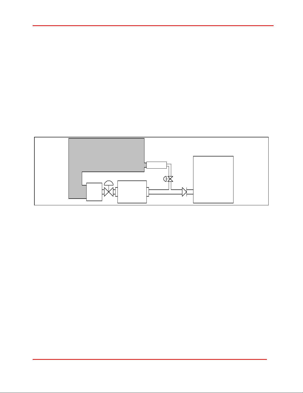
constant pressure applications. For the discussions that follow, Figure 1 depicts a
compressed air system and the relationship between the compressor and the plant air
system.
Atmosphere
Silencer
Inlet
Filter
Inlet
Valve
Compressor
Figure 1: Compressed Air System
Bypass
Valve
Check
Valve
Plant Air System
Unload
The compressor is unloaded, when no air is being supplied to the Plant Air System, and all
of the air produced by the compressor is being vented to the atmosphere. In this mode, the
inlet valve is slightly open to allow enough air to pass through the compressor for internal
cooling, prevention of rotor instability and surge avoidance. This air is then discharged
through the fully open bypass valve to the atmosphere. Typically, the compressor is set to
make a positive pressure across the first compression stage, which produces a discharge
pressure something greater than the atmospheric pressure.
The inlet valve opening required to create this positive pressure is directly related to the
horsepower consumed; therefore, careful consideration should be given to this inlet valve
position for minimizing overall power consumption.
Constant Pressure Control - Modulate
Constant pressure control is a frequently required performance control method for Centac
air compressors. If left uncontrolled, the compressor's discharge pressure would rise and
fall along the natural performance curve as system demand changed. Modulate control
satisfies the constant pressure requirement.
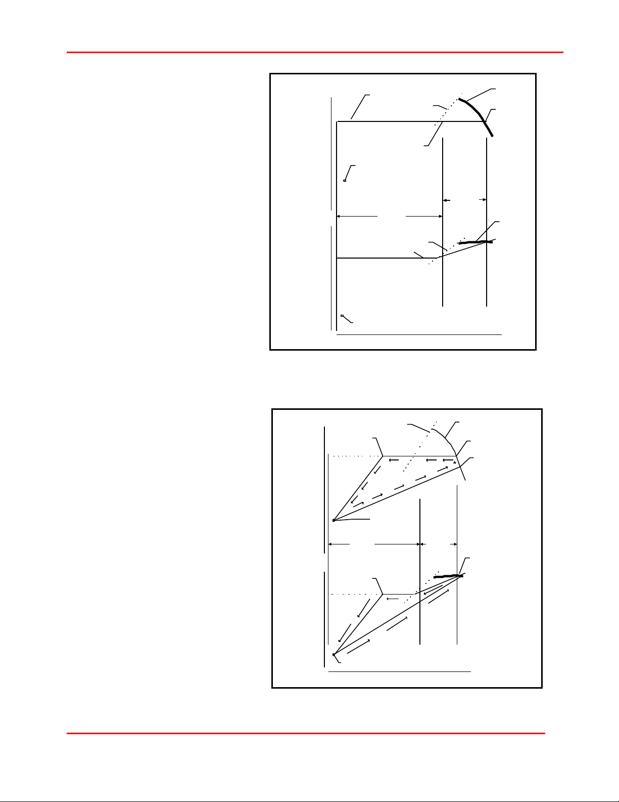
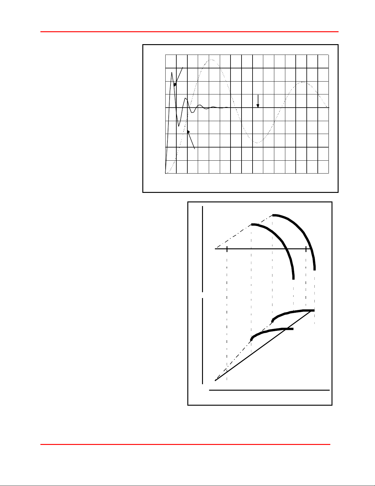
The performance map in Figure 2 shows Modulate control. Modulate maintains the system
discharge pressure at the system pressure set point as entered into the CMC by the user.
1X36003 Version 2.52
1996-1999 Ingersoll-Rand Company
Date of Issue: 18-Oct-1999
CMC TECHNICAL REFERENCE MANUAL
5
Once loaded, the compressor
will operate along the constant
pressure line until the user
switches to Unload or presses
the stop button.
Control is accomplished by
modulating the inlet valve within
the compressor's throttle range.
When system demand is less
than the minimum throttled
capacity, the discharge
pressure is maintained by
modulating the bypass valve and
venting some or all of the air to
atmosphere. This valve is
opened just prior to reaching the
surge line. Whenever the
bypass valve is open, the inlet
valve maintains its position at
the minimum throttled capacity
setting. Modulate provides a
constant discharge pressure
with variable capacity from
Discharge
Pressure
Power at
Coupling
Constant Pressure Line
Surge Line
Maximum
Throttle Point
(MinLoad)
Unloaded
Bypass
Valve
Throttle
Range
Constant Power Line
Unloaded
Surge Line
Capacity
Figure 3: Modulate Control
Inlet
Valve
Throttle
Range
Natural
Pressure
Curve
Design
Point
Natural
Power
Curve
design to zero.
This control method is used
when reliable control of the
discharge pressure is required.
Modulate is the most commonly
used control method for Centac
and X-FLO compressors.
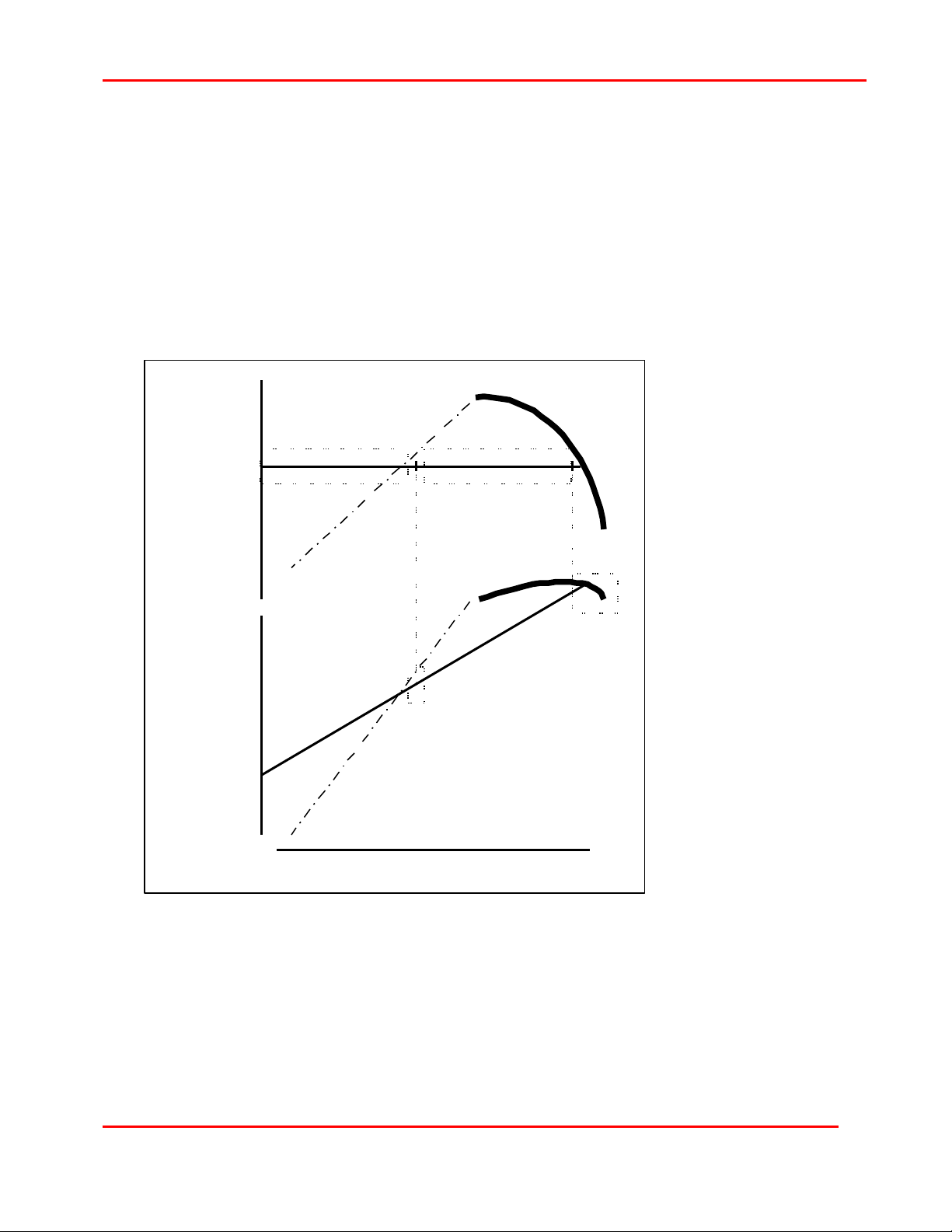
Energy Saving Control - Autodual
Autodual automatically loads the
machine when demand is high
and unloads the machine when
demand is low.
When the compressor is
controlling to pressure setpoint
and demand is within the inlet
valve throttle range, constant
pressure is maintained in the
same manner as Modulate.
When the machine is controlling
to the pressure setpoint and
system demand is low, the
compressor is operated in the
bypass valve throttle range.
Discharge
Pressure
Power at
Coupling
Surge Line
Unload
Point
Unloaded
Bypass
Valve
Throttle
Range
Unload
Point
Unloaded
Capacity
Inlet
Valve
Throttle
Range
Figure 2: Autodual Control
Natural
Curve
Design
Point
Reload Point
(Reload Percent)
Natural
Curve
1X36003 Version 2.52
1996-1999 Ingersoll-Rand Company
Date of Issue: 18-Oct-1999
6 CMC TECHNICAL REFERENCE MANUAL
Autodual automatically unloads the machine when the bypass valve is opened beyond the
Unload Point for a programmed time period called the Unload Delay Time. The Bypass
Valve Unload Point is selected to correspond with the check valve closing since at this point
the machine is not supplying the system (Figure 1). The Unload Delay Timer should be set
to prevent unloading during short excursions through the Unload Point. The Reload Percent
determines the System Pressure at which the machine will automatically load into the
system.
How does Constant Pressure Modulation Work?
The goal of constant pressure modulation is to maintain a specified discharge pressure in
the compressed air system while the capacity requirements change. Modulate control
provides constant pressure from 100 percent of the compressor's capacity to zero capacity.
Autodual control provides constant pressure from the 100 percent of the compressor's
capacity to the Unload Point.
If all plant air systems were identical in capacity usage requirements, the CMC could be
preprogrammed to respond to those changes; however, all plant air systems are not alike.
The frequency and variability of the capacity changes means that the control logic must be
flexible, so the CMC utilizes proportional plus integral control algorithms to determine the
magnitude of the signal that is sent to the inlet and bypass valves. These algorithms, or
programming logic, allow the CMC control system to be "tuned" to a specific plant air
system.
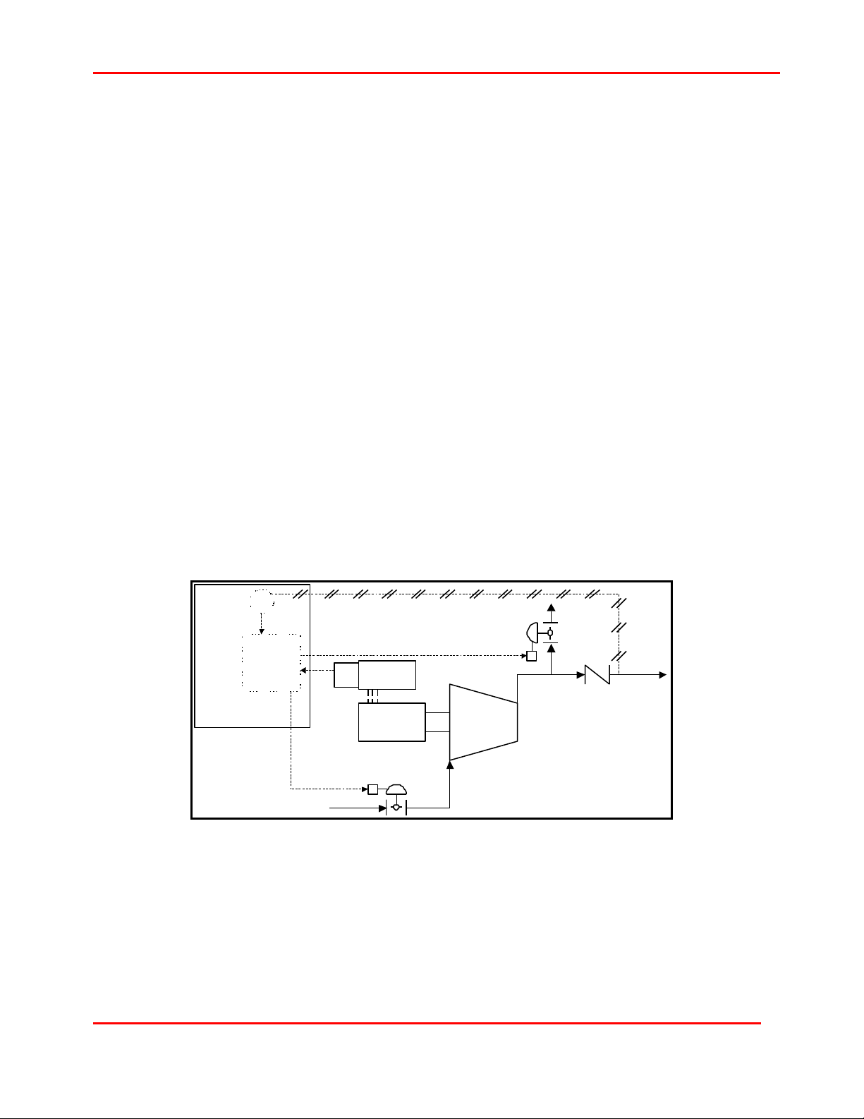
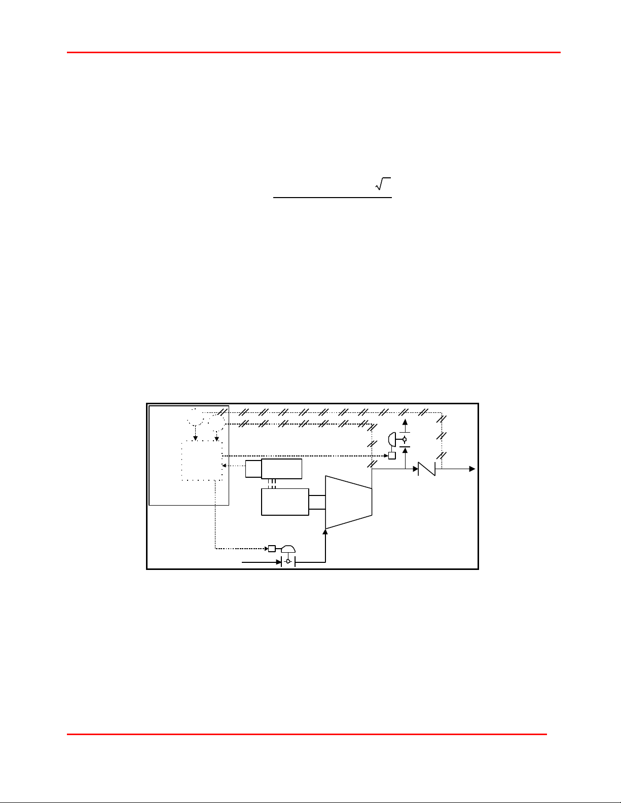
Measuring the Discharge Pressure
In order to maintain constant pressure, the system discharge air pressure must be
measured. A pressure transducer is mounted in the control panel and tubed to the
compressor discharge downstream of the check valve as shown in Figure 4.
CMC
PT
Base
Control
Module
Pneumatic Tubing
4-20 mA
StarterCT
Inlet
4-20 mA
Valve
Figure 4: Performance Control
Bypass
Valve
CompressorMotor
Check
Valve
This transducer sends a 4-20 mA signal to the CMC board. The CMC compares the
measured discharge pressure to the system pressure set point entered into the CMC by the
user through the Operator User Interface (OUI). Depending upon the difference between
these two values the CMC will send a 4-20 mA signal to "Modulate", open or close, the inlet
and/or bypass valve to maintain the specified system pressure set point.
1X36003 Version 2.52
1996-1999 Ingersoll-Rand Company
Date of Issue: 18-Oct-1999
CMC TECHNICAL REFERENCE MANUAL
Proportional Band
Proportional control varies the signal sent to the valves as a linear response to the
difference between the actual system pressure and the system pressure set point. Valve
responsiveness can be adjusted through the CMC with the proportional band, Pb, set point.
This scaling factor, graphically depicted in Figure 5, is the amount of change in the input
variable (actual minus set point pressures) to cause a full scale change in the output
variable (valve position).
In other words, if the pressure in the air system fluctuates frequently, it would be prudent to
set Pb to a low value to keep up with those system changes. Otherwise, if the system is
very stable, a larger value can be used. Pb is directly related to valve life and indirectly
related to valve cycling; so, as Pb decreases, valve life decreases and cycling increases.
As stated earlier, the CMC uses a proportional plus integral control algorithm. The result of
proportional only control is offset from the controlled variable, discharge pressure. This
means that if the set point pressure is 100, the actual pressure may only be 95. The value of
this offset depends upon the proportional band
value.
What is the valve response when the difference
between actual and set point pressures is zero?
There is no response. Proportional control only
functions when a difference or error exists. Design
discharge pressure could not be attained in a
proportional only control system. Therefore, an
integral control algorithm is added to achieve the
desired discharge pressure.
Output
Variable
(Valve Position)
Full Scale
Slow
Response
Pb
7
high
Integral Time
The offset produced by the proportional control
0
Large Change
algorithm could be eliminated by manually
readjusting the system pressure set point. Using
the example above, the set point could be reset to
Full Scale
Fast
Response
Pb
low
105 to obtain the 100 desired. Manually resetting
the set point would be required as the system
demand fluctuated. Integral control, also known as
Output
Variable
(Valve Position)
reset control, automatically resets the desired
system pressure set point. For the CMC, the rate
at which the controller resets the system pressure
setting is known as Integral Time, It, and is
expressed in units of repeats per second.
If precise control of the specified discharge
pressure is required, the It set point should be set
0
Small
Change
(Actual - Set Point Pressures)
Input Variable
for a fast value. It is inversely related to valve life
and directly related to valve cycling, therefore, as It
Figure 5: Proportional Band, Pb
decreases, valve life increases and cycling
decreases. For the CMC controlling Centac and X-FLO compressors, It values are typically
less than 1.00.
1X36003 Version 2.52
1996-1999 Ingersoll-Rand Company
Date of Issue: 18-Oct-1999
8 CMC TECHNICAL REFERENCE MANUAL
Time
Activity
Proportional Band - Low
Proportional Band - High
Opened
Set Point
Figure 6 shows the
relative valve response
over time for two
combinations of Pb and It.
As shown, when Pb is low
and It is fast, valve activity
is significant in both
magnitude and frequency
to obtain the desired set
point. The other scenario,
Pb is high and It is slow,
has relatively little valve
activity, and may never
reach the set point
position.
Valve
Integral Time - Fast
Integral Time - Slow
Proportional Band and
Integral Time are
Closed
variables used internally
by the control system to
determine valve response
and direction for a given
compressed air system. Each has an
optimum value based upon the
system's characteristics. Determining
these optimum values is a trial and
error exercise. These set points should
be re-evaluated any time there is a
major change in the compressed air
system.
Up to this point, constant pressure
control has been accomplished with an
analog input (system pressure) and two
analog outputs (inlet valve and bypass
valve position). How is motor current,
the other analog input, used for
constant pressure control? When does
the bypass valve modulate as opposed
to the inlet valve?
Figure 6: Proportional Plus Integral Control
T
cold
T
hot
Discharge PressurePower at Coupling
MinLoad
MaxLoad
Motor Current, MinLoad and MaxLoad
Motor current, in units of power
(normally amps), has two functions in
the CMC. The first is over current
protection for the main motor, and is
referred to as MaxLoad or High Load
Limit (HLL). The second function
determines the point at which the
bypass valve begins to modulate for
Capacity - Mass Flow
Figure 7: MinLoad and MaxLoad
1X36003 Version 2.52
1996-1999 Ingersoll-Rand Company
Date of Issue: 18-Oct-1999
CMC TECHNICAL REFERENCE MANUAL
controlling pressure. This point is called MinLoad or Throttle Limit (TL). The location of these
two points is graphically depicted on the pressure and power versus capacity curves as
shown in Figure 7.
MaxLoad or High Load Limit (HLL) setpoint, in units of amps, is a parameter entered into
the CMC that prevents the main drive motor from overloading. Once this value is reached,
the CMC logic limits the inlet valve from opening any further. This action constrains the
motor by limiting the amp draw to the maximum allowable service factor amps by using the
inlet valve MaxLoad PID loop to maintain the MaxLoad current setpoint.
When the motor is sized for cold conditions, there are circumstances when MaxLoad will
never be reached. For example, the value of MaxLoad as shown in Figure 7, cannot be
attained for the T=hot curve because it is beyond the maximum compressor capability; that
is, the inlet valve is fully
open. This scenario
never limits the inlet
valve.
When ambient
conditions produce the
T=cold curve, the
compressor will not be
able to achieve the
maximum capacity
because it is beyond
the MaxLoad value.
Since MaxLoad is less
than or equal to the
motor nameplate FLA
times the adjusted
service factor, the
maximum compressor
capacity at T=cold
could only be reached
if the motor were sized
for the T=cold
condition.
Discharge
Pressure
Power at
Coupling
Amps
Bypass Valve
Pressure PID
Control Zone
TL
Inlet Valve
MinLoad PID
Control Zone
Inlet Valve
Pressure PID
Control Zone
HLL
Inlet Valve
MaxLoad PID
Control Zone
9
MinLoad Control
Capacity - Mass Flow
Setpoint in units of
amps is the power
value at which the
CMC transfers modulation control from the inlet to the bypass valve. The reason for this
transfer is to prevent the compressor from entering into a surge condition. The bypass valve
vents air to the atmosphere and maintains the pressure setpoint by using the bypass valve
pressure PID loop. At the same time, the inlet valve maintains the MinLoad setpoint by
using the inlet valve MinLoad PID loop; therefore, once the MinLoad setpoint is reached,
the compressor continues to produce a constant amount of air. Part of this air goes to the
Plant Air System, and the remainder is blown off. Even though the Plant Air System receives
only a portion of the air produced, the amount of power remains constant.
1X36003 Version 2.52
1996-1999 Ingersoll-Rand Company
Date of Issue: 18-Oct-1999

10 CMC TECHNICAL REFERENCE MANUAL
The following table presents seven capacity requirements for a plant air system. At each of
the capacities, the table shows the compressor output, valve position, discharge pressure
and power. Each of these values represents a percentage and is only an example. P2 is the
specified discharge pressure and P0 is the barometric pressure.
System Compressor Compress
or
Require
d
Capacity
0 Off 0 0 100 0 0
0 Unloaded 10 10 100 >P
100 Full Load 100 100 0 P
75 MinLoad 75 70 0 P
50 MinLoad 75 70 25 P
25 MinLoad 75 70 50 P
0 MinLoad 75 70 100 P
Operating
State
Output
Capacity
Open Position
Inlet
Valve
Bypass
Valve
Discharge
Pressure Power
0
2
2
2
2
2
20
100
80
80
80
80
From the table above, once the system required capacity moves below 75 percent, the
compressor still produces 75 percent capacity with 80 percent of the power. If the system
needs only 25 percent capacity, it will still have to pay for 80 percent of the power. This is
why it is important to open the bypass valve at the last possible moment; therefore, setting
MinLoad properly is critical for efficient energy management.
Surge Control
Surge is the reversal of flow within a dynamic compressor that takes place when the
capacity being handled is reduced to a point where insufficient pressure is being generated
to maintain flow. This condition can potentially damage the compressor if it is severe and is
allowed to remain in that state for a prolonged period; therefore, control and prevention is
required.
Control Methodology
Surge prevention is accomplished by opening the bypass valve prior to reaching the surge
point. The point at which the bypass valve opens is MinLoad. By blowing a portion of the air
to the atmosphere, the compressed air system gets the air that it demands. The
compressor avoids surge because it is still producing a constant air capacity.
Surge Detection
Even though the CMC controls to prevent surge, it can still occur. Insufficient rise to surge,
rapid changes in system discharge pressure, and various other reasons exist for a
compressor to surge.
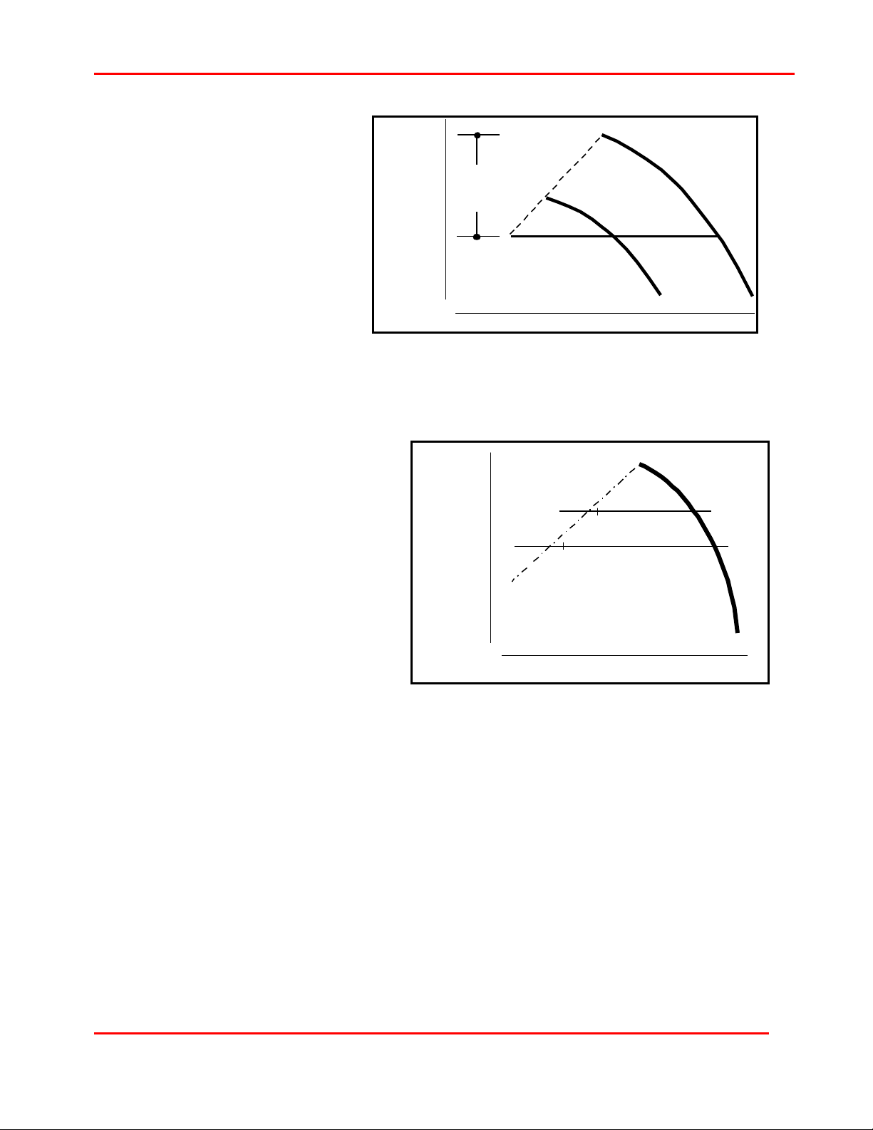
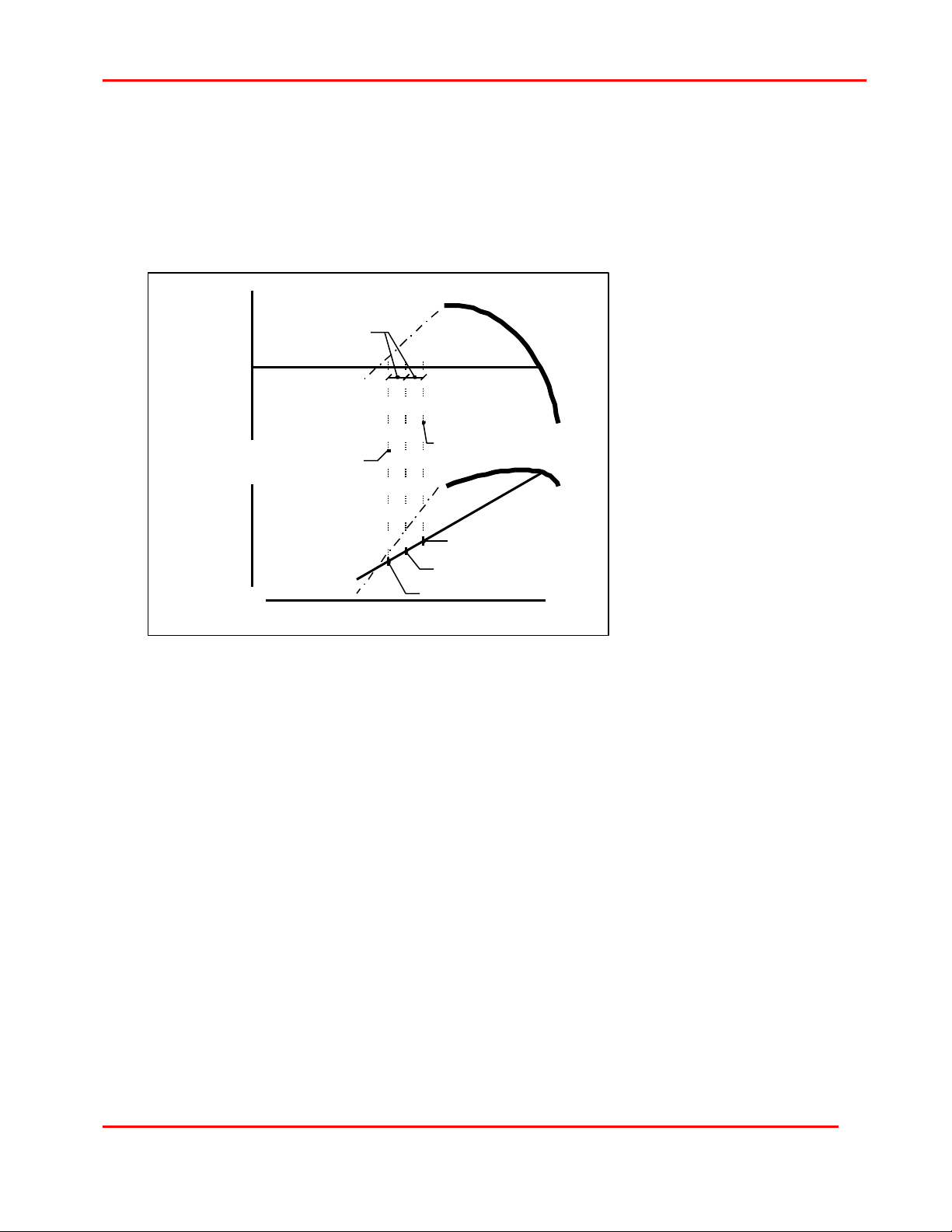
Insufficient Rise To Surge
Rise to surge is the percentage of the compressor's surge pressure to discharge pressure
(see Figure 8). When an insufficient rise to surge situation exists, small fluctuations in the
air system demand and ambient temperature can cause the compressor to surge.
From Figure 8, when T=cold, there is sufficient rise to surge. As the ambient temperature
increases to T=hot, the amount of rise to surge decreases because the discharge pressure
is remaining constant and the natural curve is changing with temperature.
1X36003 Version 2.52
1996-1999 Ingersoll-Rand Company
Date of Issue: 18-Oct-1999
CMC TECHNICAL REFERENCE MANUAL
Capacity
Typically sufficient rise to surge
exists when a ten- percent rise
to surge can be achieved for the
hottest ambients that are
expected for the site. If this
design criterion is followed, the
control system should be able
to prevent surge for variations in
air demand and inlet
temperature. The same design
methodology applies for
changes in cooling water
temperature for multi-stage
compressors.
Changes in System Discharge Pressure
MinLoad corresponds to a specific
constant discharge pressure;
therefore, if the discharge pressure
changes, MinLoad must be reset to
properly control surge. As shown in
Figure 9, when the discharge
pressure is changed from point 1 to
2, a surge can occur at point 2 if
MinLoad is not reset.
Discharge
Pressure
Discharge
Pressure
Rise
To
Surge
T=hot
Figure 8: Rise To Surge
TL
T=cold
1
TL
11
2
Changes in system discharge
pressure also apply, but more subtly,
when the compressor begins to age.
Dirty inlet filter elements and fouled
Capacity - Mass Flow
coolers can change the
compressor's natural curve; so
MinLoad should be checked
Figure 9: Changes in Discharge Pressure
periodically to prevent surge from an
incorrect setting.
Rapid System Demand Changes
When the system demand varies rapidly over a wide range of capacity, the controller may
not react fast enough to open the bypass valve to prevent surge. The CMC reads discharge
pressure, motor amps, and approximately twenty other pressure and temperature inputs;
plus controls the inlet and bypass valve position. The time required to do all of this
approximately 100 milliseconds. When the controller is too slow to react, it is referred to as
"driving through MinLoad". The only prevention for a situation like this is to set MinLoad at a
more conservative value. The only negative implication to this is reduced energy savings,
because the bypass valve is opened early.
Incorrect Instrumentation Output
If the instrumentation, defined in Figure 4, is improperly calibrated or gives inaccurate
readings, the compressor could surge even though the CMC thinks it should not. Areas of
1X36003 Version 2.52
1996-1999 Ingersoll-Rand Company
Date of Issue: 18-Oct-1999
12 CMC TECHNICAL REFERENCE MANUAL
746
concern are insufficient power air, incorrect valve transducer calibration, and repeatability of
both inlet and bypass valves. If the valves are being sent signals for specific movements
and they do not respond by moving to the new positions, then the CMC has very little
chance of correctly controlling surge, or even the discharge pressure.
As discussed earlier, the CMC uses motor current as the standard method for determining
when to open the bypass valve. The time to begin opening the bypass valve is near
MinLoad amps. The equation,
I V PF
GHP
× × × ×η3
=
motor
indicates that horsepower is directly related to current; it is, but it is also related to voltage.
This is not normally a concern because voltage is primarily constant. However, there are
some locations where extreme voltage variations do exist. In these circumstances, the CMC
cannot correctly determine when it reaches MinLoad and a surge can occur. For these
applications, an optional watt transducer can be used to avoid this situation.
How is Surge Detected?
Note that it has been shown that even though the CMC has surge prevention logic, a surge
can still occur. The CMC has a surge detection system comprised of a surge pressure
transducer and motor current transformer (see Figure 10). The CMC senses surge when
the rate of change in last stage discharge pressure and the rate of change in motor current
are greater than the surge sensitivity setpoint value. When this occurs, the CMC will alarm
and unload the compressor.
CMC
PT
Base
Control
Module
PT
4-20 mA
Pneumatic Tubing
4-20 mA
StarterCT
Inlet
Valve
CompressorMotor
Bypass
Valve
Check
Valve
Figure 10: Changes in Discharge Pressure
Surge AbsorberTM
When the controller recognizes that a surge occurred, the compressor will unload. With the
Surge AbsorberTM feature enabled, the controller will increment the bypass valve position by
a fixed percentage, send the inlet valve to the MinLoad point (if it is not already there) and
then let normal system demand reload to the operating pressure. This process will repeat
up to three times within a ten-minute period. If the compressor surges four times in ten
minutes, the compressor will remain unloaded until an operator presses the reset button.
Each detected surge drives a Surge Event to the Event Log. If the compressor unloads do
to repeated surges, a Surge Unload Alarm Event is driven to the Event Log.
1X36003 Version 2.52
1996-1999 Ingersoll-Rand Company
Date of Issue: 18-Oct-1999
CMC TECHNICAL REFERENCE MANUAL
Surge Indexing
Since the setting of MinLoad Control Setpoint is sensitive to many variables in a
compressed gas system, there is potential for the setting to require adjustment throughout
the operation of the compressor. When MinLoad is set incorrectly, one of two things can
happen. When MinLoad is set too high, the compressor will consume excessive power at
MinLoad. When MinLoad is set too low, the compressor is allowed to go past the surge line
and surge occurs.
When Surge Indexing is
MinLoad
Surge
Index
Increment
Discharge
Pressure
MinLoad Control Setpoint
MinLoad Control Setpoint #3
(currently active)
MinLoad Control Setpoint #1
MinLoad Control Setpoint #1
Power at
Coupling
Amps
MinLoad User Setpoint
(reset returns control here)
Capacity - Mass Flow
match the new setting and when reset the MinLoad Control Setpoint is reset to the original
MinLoad.
enabled, it corrects the
situation when MinLoad is
set too low by automatically
adjusting MinLoad to a
higher value upon a surge.
The indexed setting,
MinLoad Control Setpoint
will remain in effect until
MinLoad User Setpoint is
manually changed on the
Operator User Interface, or
the Reset button is held for
more than five seconds.
When MinLoad User
Setpoint is manually
changed, the MinLoad
Control Setpoint is
automatically changed to
13
Entering a non-zero number into the MinLoad Surge Index Increment variable enables surge
Indexing.
1X36003 Version 2.52
1996-1999 Ingersoll-Rand Company
Date of Issue: 18-Oct-1999

14 CMC TECHNICAL REFERENCE MANUAL
Oil System Control
The CMC panel provides control of the prelube pump and lube oil heater in the starting
sequence, during normal operation and after compressor stops or trips.
Prelube Pump
The prelube pump is started when the panel power is on and Seal Air is present. The
prelube pump stops after the compressor start button is pushed and the programmable
timer “Start Time” has expired. The pump does not come on again until the Stop key is
pressed, and will remain on until the panel power is turned off or Seal Air is lost.
Oil Heater
The oil heater is thermostatically controlled. When the oil temperature is below the set point
temperature, the oil heater is energized, above the set point temperature it is de-energized.
The oil heater control does not have any interaction with the microprocessor board and is
designed to operate with the control panel de-energized as long as three-phase power is
available.
1X36003 Version 2.52
1996-1999 Ingersoll-Rand Company
Date of Issue: 18-Oct-1999

CMC TECHNICAL REFERENCE MANUAL
Protection and Monitoring
Each CMC base module has twenty-three analog inputs, sixteen digital inputs, four analog
outputs and sixteen digital outputs for control, protection and monitoring. These input
functions provide the CMC with information about the compressor. The CMC board uses the
output functions to communicate to the user and perform actions like starting the
compressor and turning on the prelube pump. All of these inputs and outputs are required to
interface physical actions to and from the electronics.
Analog Functions
An analog function is one in which an electrical signal represents a specific pressure,
temperature, vibration and current input; or valve position output. As these inputs and
outputs fluctuate, the electrical signal to and from the microprocessor board also fluctuates
proportionally to the amount of change.
Analog Inputs
Twenty-one grounded and two floating analog inputs are used for protection, monitoring and
control. Each input used for protecting the compressor is programmed for alarm and trip
indication. Each of these functions is pre-programmed with the function title, engineering
units, range, alarm and trip values, so no configuration is required upon receipt by the
customer.
15
The CMC uses pressure transmitters to measure pressure, resistance temperature
detectors (RTD) and transmitters to measure temperature, eddy current based vibration
transmitters to measure shaft vibration and a current transformer to measure the motor
current.
The CMC logic used for the protective alarm and trip functions is as follows: if the actual
value of the input is greater than or equal to the alarm or trip value, indicate the condition.
This logic is used for all inputs except, low oil pressure and temperature where the logic is
reversed. To prevent nuisance alarms and trips, all standard analog inputs use an alternate
alarm and trip value during the stopped, starting, and coasting states. The alternate
setpoints cannot be edited through the Operator User Interface.
Analog Outputs
Two of the available four analog output functions are for inlet and bypass valve positioning.
These are only output functions. The standard configuration for a CMC has no input
information as to the valve location. The CMC calculates the position based upon where the
valves are supposed to be and sends those signals to the valves.
Digital Functions
A digital function is one in which the presence of an electrical signal indicates ON or YES,
and the lack of that signal represents OFF or NO. This is analogous to a light switch that
has only two states, ON or OFF. The term "discrete" is also used instead of digital in many
instances. The term that will be used throughout this documentation shall be digital.
Digital Inputs
The sixteen digital inputs provide status of field switches. Emergency Stop and Low Seal Air
Pressure trip are standard. Any of these inputs can be configured as an alarm or trip. All
inputs operate on 24 VDC power.
1X36003 Version 2.52
1996-1999 Ingersoll-Rand Company
Date of Issue: 18-Oct-1999

16 CMC TECHNICAL REFERENCE MANUAL
Digital Outputs
The sixteen digital outputs are used by the CMC to start the prelube pump, energize the
main starter contacts, indicate that an alarm or trip condition exists, indicate that the
compressor is unloaded, activate the running unloaded shutdown timer and to sound the
horn. Outputs can operate on 120 VAC, 60 Hz, single-phase power or 24 VDC power.
1X36003 Version 2.52
1996-1999 Ingersoll-Rand Company
Date of Issue: 18-Oct-1999
CMC TECHNICAL REFERENCE MANUAL
Compressor Operating Methodology
In the following description of compressor operation, the term “state” is used to indicate
what the compressor is doing, or mode of operation, at any given time. These operating
states exist in a hierarchy. For example, the two highest level states are “Stopped” and
“Rotating”. All other states exist at a level below these two states.
17
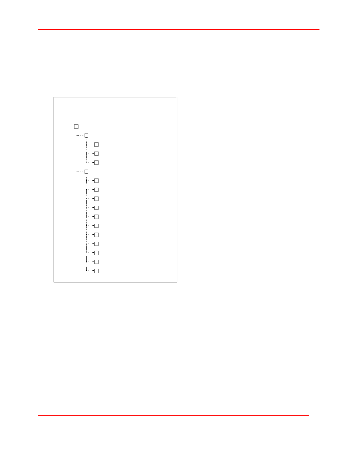
Compressor Operating States
Motor Driven Packages
+
Compressor
+
Stopped
Waiting
Not Ready
Ready
+
Rotating
Starting
Unloaded
A-D Unloaded
Surge Unload
Loading
MinLoad
Loaded
Full Load
MaxLoad
Unloading
Coasting
common and quite often overlooked reason for the compressor being “Not Ready” is when
the Emergency Stop push button has been engaged. This state can exist indefinitely.
This state implies that the compressor is or
NOT rotating. It is important to note that this
is an implication only. If the instrumentation is
not working properly or the system is setup
improperly, the compressor could be rotating.
Waiting
After the panel power is energized, the
controller starts the Waiting Timer and does
not allow further User operation until after the
timer expires. This timer is set at the factory
for two minutes (120 seconds) and is not
adjustable. This period allows the
compressor prelube pump to circulate oil
throughout the casing and prevents restarting
while the compressor is coasting down
during an electrical interruption.
Not Ready
When in this state, the compressor is “Not
Ready To Start”. This state is entered when
the Waiting Timer has expired and any time
that a compressor trip has been identified or
a stop command has been issued. A very
Stopped
Ready
Similar to the previous state, this state could be redefined as “Ready to Start”. This state is
entered when all compressor permissive functions have been satisfied. This state can exist
indefinitely.
Rotating
This mode does not necessarily mean that the compressor is actually rotating. It means that
it is rotating or rotation is pending and expected.
Starting
Any time after the compressor is ready and a start command is given, this state is entered.
The goal for this period is to get the compressor to rated speed and running unloaded.
“Starting” is allowed for only the Start Timer period and is adjustable. This time period is
1X36003 Version 2.52
1996-1999 Ingersoll-Rand Company
Date of Issue: 18-Oct-1999

18 CMC TECHNICAL REFERENCE MANUAL
limited to a maximum of one minute, or 60 seconds. The reason for the limit is to prevent
the compressor from operating in the critical speed for an extended period. Stage vibration
alarm and trip setpoints are increased during this period to get the compressor through the
critical speed region. After the compressor has “Started”, the alarm and trip setpoints are
adjusted back to their original values. The same procedure occurs for stage air temperature
also.
This state exits only after the Starting Timer has expired. THE COMPRESSOR IS ALWAYS
STARTED UNLOADED. On exit of “Starting”, the compressor will return to the mode that it
was in the last time it ran. For example, typical operation implies that prior to stopping the
compressor, the Unload key is pressed. If this occurred, then the compressor will remain in
“Unload” after starting. If the compressor is was running and tripped, the compressor will
automatically return to the “Loaded” mode on exit of the Starting state. The User may also
press the Load or Unload key prior to pressing the Start key to force the compressor to into
either post-Starting state.
Unloaded
The compressor is in this state after a start (and Load Selected is not in effect) or when the
User issues an unload command. A-D Unloaded and Surge Unload are also considered
states. However, these two states are really just reasons for being in the Unloaded state. AD Unloaded means “AutoDual Unloaded” which occurs when AutoDual is enabled and the
system pressure has been high enough for a long enough time to drive an unload
command. “Surge Unload” is similar in that a surge event drives the unload command
instead of AutoDual. These states can exist indefinitely.
Loading
When a valid load command is issued, the compressor will enter this state. This state
exists until the MinLoad state is satisfied. The duration of this state depends upon PID
settings for the inlet valve at the MinLoad state and the demand for air.
MinLoad, Loaded, Full Load and MaxLoad
These states transition among themselves as demand for air changes. “MinLoad” means
that the bypass valve is controlling pressure and the inlet valve is maintaining the MinLoad
Control Setpoint. “Loaded” means that the inlet valve is controlling pressure and the bypass
valve is closed. “Full Load” occurs when the inlet valve has reached the full open or 100%
position. “MaxLoad” means that the inlet valve is maintaining the MaxLoad Setpoint to
prevent motor damage. In both the “Full Load” and “MaxLoad” states, system pressure will
be lower than setpoint pressure.
Unloading
This state occurs when a valid Unload command is issued and will persist until the
compressor reaches the Unloaded state.
Coasting
When a trip or any stop command is issued and the compressor is running, the motor will
be de-energized and the compressor will begin to coast to a Stopped state. This state will
remain as long as the adjustable Coast Timer is in effect. At the end of the timer, the
compressor will enter either the Ready or Not Ready state.
1X36003 Version 2.52
1996-1999 Ingersoll-Rand Company
Date of Issue: 18-Oct-1999
CMC TECHNICAL REFERENCE MANUAL
WARNING
Failure to set the Coast Timer for a period greater than or equal to the actual
coasting time can result in compressor damage.
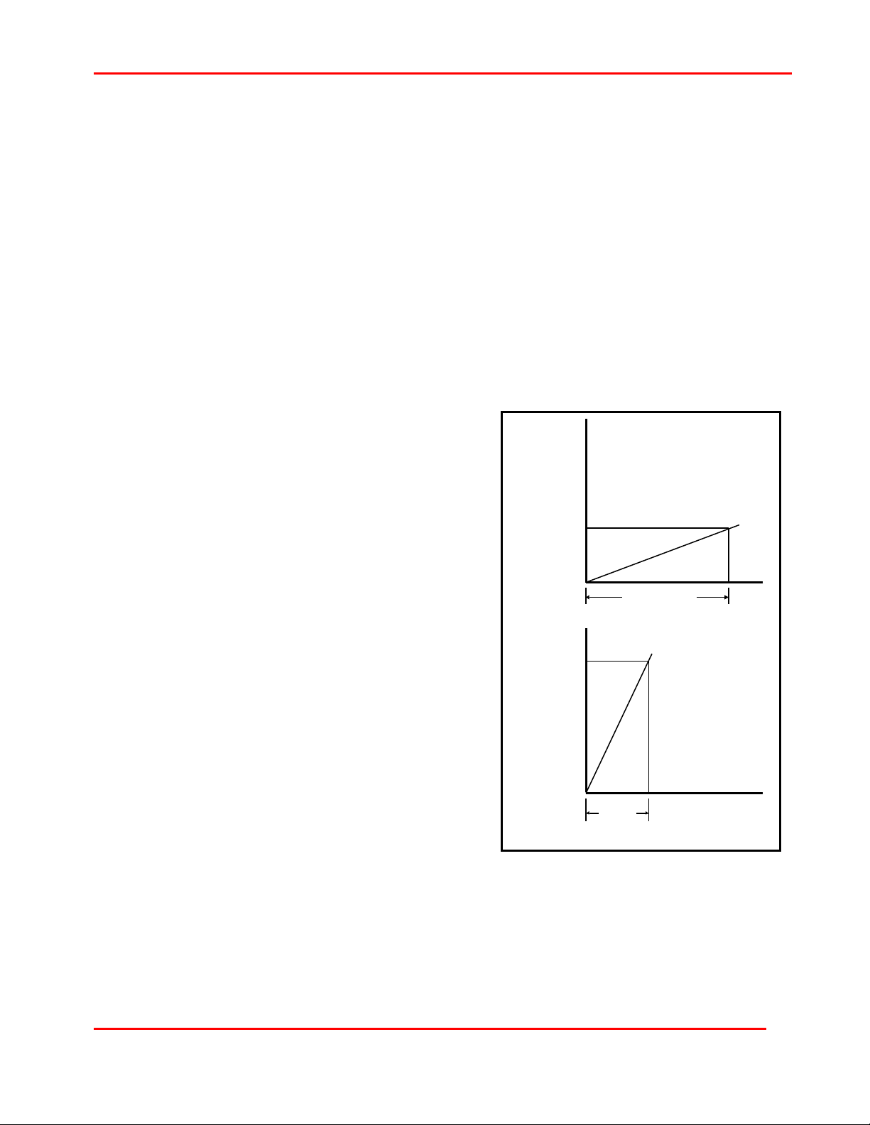
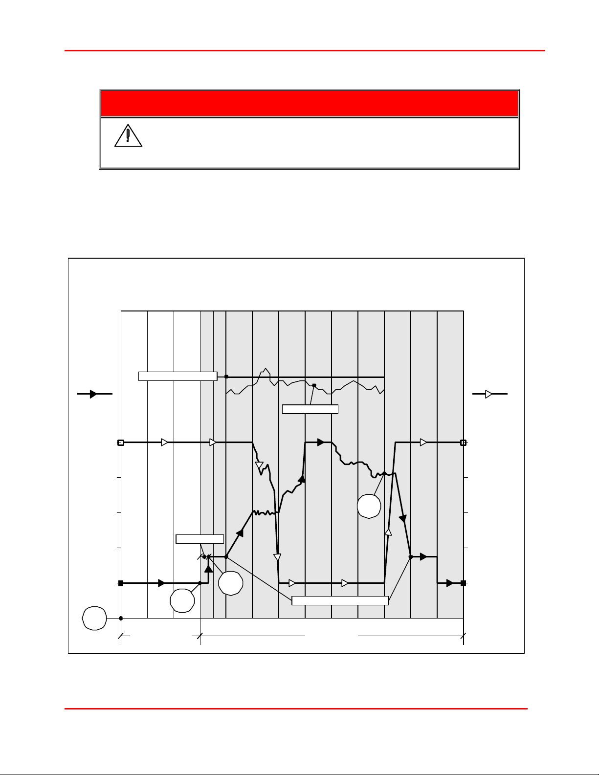
Compressor Operating States
The following diagrams graphically depict the states relative to valve position. This diagrams
is provided to assist in the understanding of overall compressor operation.
Compressor Operating States
with Valve Position
19
Inlet
Valve
%
100
75
50
25
0
Power
On
milli
amps
20
16
12
Waiting
System Pressure Setpoint
8
4
Ready
Not Ready
Tight Closure
Start
Starting
Unloaded
Load
Loading
MinLoad
System Pressure
Loaded
Full Load
Inlet Valve Unload Position
Loaded
Unload
MaxLoad
Unloading
Coasting
Unloaded
Bypass
Valve
milli
%
amps
100
4
75
8
50
12
25
16
0
20
RotatingStopped
1X36003 Version 2.52
1996-1999 Ingersoll-Rand Company
Date of Issue: 18-Oct-1999
20 CMC TECHNICAL REFERENCE MANUAL
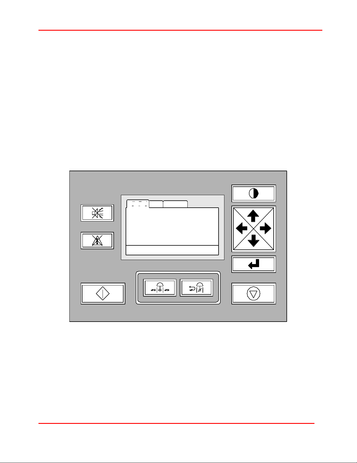
User Interface
OUI (Operator User Interface)
User interface is defined as the means by which people interact with the compressor control
system. The standard configuration of the CMC has two components of the user interface.
They are the OUI and the device plate. The key component of "easy to use" is that there are
only twelve buttons to press on the OUI and four buttons, lights, and switches on the device
plate.
The CMC OUI consists of six command buttons (Start, Stop, Load, Unload, Acknowledge
and Reset), four navigation keys (Up, Right, Left and Down), an Edit mode selection key
(Enter) and a Contrast key. These keys in conjunction with the 240x128-pixel graphics
display make up the user interface to the compressor. The bezel that surrounds the OUI
ensures that the NEMA 4 rating is maintained for the OUI.
CENTAC
Microcontroller
SYSTEM
System
Pressure
Pressure
Setpoint
Motor
Current
Running Hours 11445
Loaded
INFO
SETTINGS
105.3
105.0
173.4
Inlet
Valve
Bypass
Valve
22JUL96 12:00:00
95
0
Load Selected
Remote
1/2
1X36003 Version 2.52
1996-1999 Ingersoll-Rand Company
Date of Issue: 18-Oct-1999
 Loading...