

Page 1
OPERATOR’S MANUAL 66506-B
INCLUDING: OPERATION, INSTALLATION & MAINTENANCE
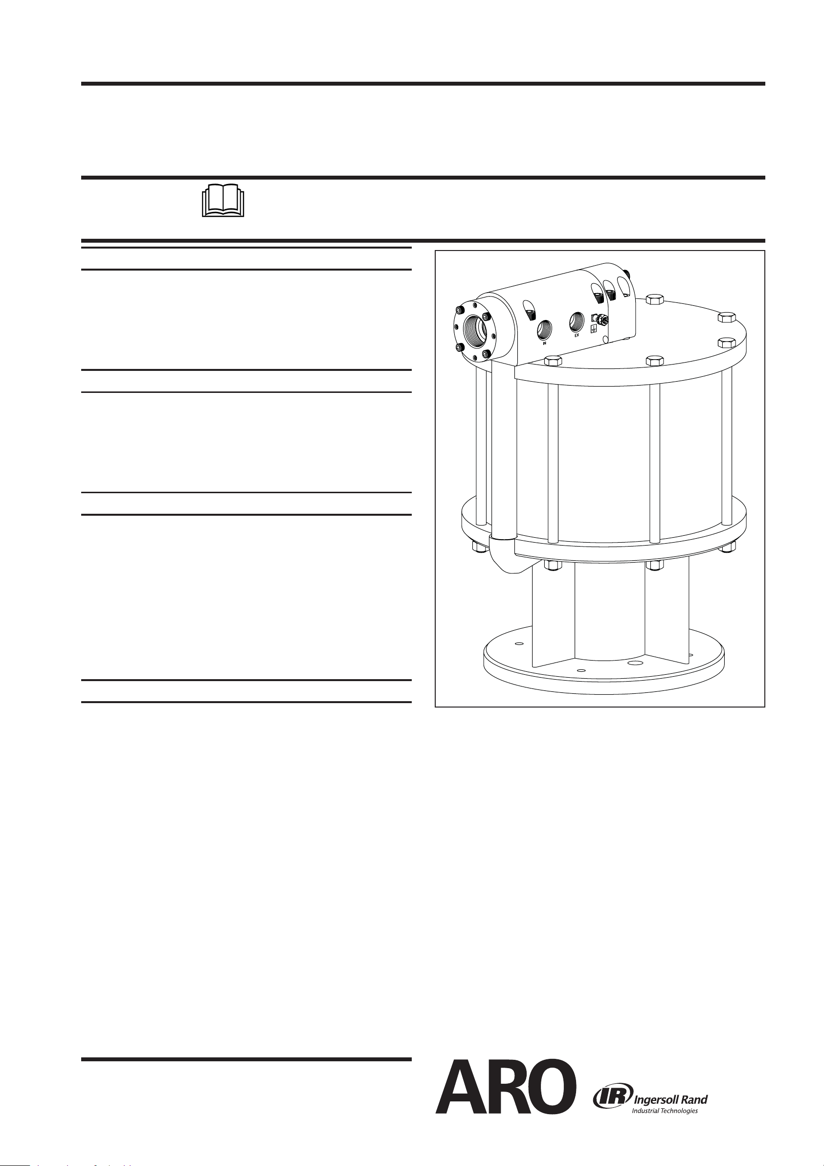
12” AIR MOTOR
66506-B AIR MOTOR
RELEASED: 2-11-00
REVISED: 8-1-11
(REV. E)
6” STROKE
READ THIS MANUAL CAREFULLY BEFORE INSTALLING,
OPERATING OR SERVICING THIS EQUIPMENT.
It is the responsibility of the employer to place this information in the hands of the operator. Keep for future reference.
SERVICE KITS
Use only genuine ARO® replacement parts to assure
y
compatible pressure rating and longest service life.
637112 service kit includes the necessary soft parts for
y
normal service of the entire air motor.
637113 service kit is a replacement valve kit.
y
GENERAL DESCRIPTION
The 12” air motor is a power unit used with a two-ball or
chop-check pump. It utilizes tie rod construction for easy
breakdown and it connects to the lower pump end with tie
rods for easy operation. Consult the pump model operator’s
manual for speci c instructions.
OPERATING AND SAFETY PRECAUTIONS
DO NOT EXCEED MAXIMUM AIR INLET PRESSURE OF 90
P.S.I. (6.2 bar) OR 75 CYCLES PER MINUTE.
CAUTION: High pressure equipment - Always disconnect air
supply and relieve material pressure before attempting to
service.
A ground lug is located on the air motor. This ground lug allows proper grounding of the pump.
AIR AND LUBE REQUIREMENTS
A filter capable of filtering particles larger than 50 microns
should be used with a lubricator.
Filtered and oiled air will allow the pump to operate more ef ciently and yield a longer life to operating parts and mechanisms.
Use an air line lubricator and keep it supplied with a good
grade of S.A.E. #90W non-detergent gear oil set at a rate not
to exceed approximately 1 drop per minute.
Figure 1
INGERSOLL RAND COMPANY LTD
209 NORTH MAIN STREET – BRYAN, OHIO 43506
(800) 495-0276 y FAX (800) 892-6276 © 2011 CCN 99834897
www.ingersollrandproducts.com
Page 2
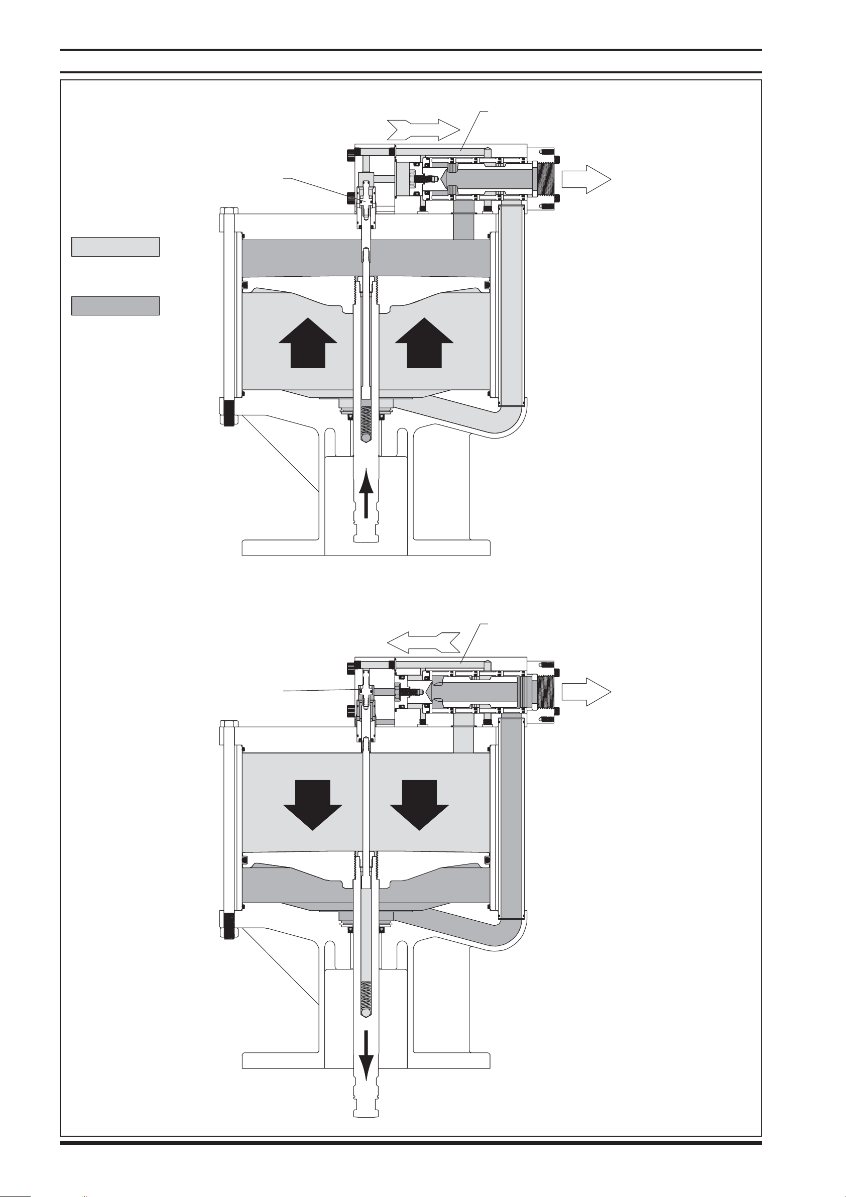
THEORY OF OPERATION
AIR MOTOR FUNCTION DURING UPSTROKE
CONSTANT AIR PRESSURE
SPOOL
Air Pressure
Exhausted Air
Pilot down
EXHAUSTED AIR
AIR MOTOR FUNCTION DURING DOWNSTROKE
Pilot up (exhaust)
CONSTANT AIR PRESSURE
SPOOL
EXHAUSTED AIR
Figure 2
Page 2 of 8 66506-B (en)
Page 3

DISASSEMBLY / ASSEMBLY
AIR MOTOR DISASSEMBLY
NOTE: All threads are right hand.
Place the air motor in an up-stroke position by pushing
1.
(43) piston assembly toward the top of the motor.
Remove six (26) cap screws from the top of (27 and 30)
2.
blocks.
Remove (27 and 30) blocks from (22) head plate.
3.
Remove (34) tube from (46) base assembly. Remove two
4.
(33) “O” rings from (34) tube and one (33) “O” ring from
the bottom of (30) block manifold.
Remove four (26) cap screws from the end of (27) block.
5.
Separate (27) block from (30) block manifold and remove
6.
(28 and 29) “O” rings.
Remove 3/4 - 14 N.P.T. pipe plugs from the two exhaust
7.
ports, if applicable.
Using a 1/2” socket on (8) cap screw, turn (20) spool
8.
clockwise to align opening or slot in (20) spool with the
3/4 - 14 N.P.T. exhaust port nearest the (8) cap screw.
Insert a 1/4” rod or similar device thru the exhaust port of
9.
(30) block manifold and into the opening or slot of (20)
spool. This rod will prevent rotation of (20) spool when
removing (8) cap screw and (9) washer. CAUTION: Do
not permit this rod to rest against (17) spacer legs,
which could cause breakage of (17) spacer.
Remove (8) cap screw and (9) washer.
10.
Unscrew four (32) cap screws and remove (31) cap as-
11.
sembly.
Remove (20) spool out the “exhaust end” of (30) block
12.
manifold and remove (11) piston out the other end.
From the “exhaust end” of (30) block manifold, remove
13.
four (19) washers, four (17) spacers, four (18) “O” rings,
ve (15) “O” rings, (16) washer, (14) “U” cup, (13) gland and
(10) “O” ring.
Remove (12) “U” cup from (11) piston.
14.
Using the wrench flats provided, remove the (2) piston
15.
assembly from the (5) extension rod.
Remove (1 and 3) “O” rings from (2) piston assembly.
16.
Remove (4) washer, (6) cylinder, two (7) “O” rings and (24)
17.
“U” cup from (22) head plate.
Remove two (7) “O” rings and (24) “U” cup from (6) cylin-
18.
der.
Remove eight (47) nuts from (49) cap screws.
19.
Remove eight (49) cap screws from (22) head plate and
20.
(46) air motor base assembly.
Remove (22) head plate from (37) air cylinder, then re-
21.
move (36) “O” ring from (22) head plate.
Pull upward on (37) air cylinder until (43) piston assem-
22.
bly separates from the (46) base assembly. If, in this step,
the (43) piston assembly is not pulled from the (46) base
assembly, then remove it after removing the (37) air cylinder.
If the (37) air cylinder and (43) piston assembly are re-
23.
moved as one unit, then remove the (43) piston assembly
from the (37) air cylinder.
Remove the (36) “O” ring from the (46) base assembly.
24.
Remove (40) retaining ring, (44) guide washer and (41) “U”
25.
cup from (46) base assembly.
Remove the (50) “O” ring from the (43) piston assembly.
26.
Unscrew (5) extension rod from (39) valve rod by holding
27
.
the (39) valve rod with an adjustable type pliers and using a wrench on the wrench ats provided at the top of
the (5) extension rod.
Remove the (48) screw from the (43) piston assembly.
28.
Remove the (39) valve rod, (45) spring and (42) ball from
29.
the (43) piston assembly.
AIR MOTOR ASSEMBLY
1.
Place the (39) valve rod thru the (48) screw.
2.
Clean the threads of the (39) valve rod and the (5) extension rod. Apply Loctite 271 to these threads and screw
the (5) extension rod to the (39) valve rod and tighten
by holding the (39) valve rod below the threads with an
adjustable type pliers and using a wrench on the ats of
the (5) extension rod. CAUTION: Do not mar or damage
the nish on the (5) extension rod.
Place the (42) ball and (45) spring into the (43) piston as-
3.
sembly.
Place the (39) valve rod and (5) extension rod into the (43)
4.
piston assembly. Apply Loctite 271 to the threads of the
(48) screw and thread the (48) screw into the (43) piston
assembly and tighten.
Assemble the (50) “O” ring to the groove in the (43) pis-
5.
ton assembly.
Assemble the (36) “O” ring to the groove in the (46) air
6.
motor base assembly.
Assemble the (41) “U” cup (lips up), (44) guide washer
7.
and (40) retaining ring into the (46) base assembly.
Assemble the (43) piston assembly into the (46) base as-
8.
sembly, being careful not to damage the (41) “U” cup.
Lubricate the inside diameter of the (37) air cylinder and
9.
slide it down over the (43) piston assembly and onto the
(46) air motor base assembly (see gure 4).
Assemble the (36) “O” ring to the groove in the (22) head
10.
plate.
Align the notch in the (22) head plate with the port in
11.
the (46) air motor base assembly and press the (22) head
plate down until it is seated against the (37) air cylinder.
Assemble eight (49) cap screws thru the (22) head plate
12.
and (46) air motor base assembly.
Assemble eight (47) nuts on the (49) cap screws and
13.
tighten alternately and evenly.
Assemble two (7) “O” rings to the grooves in the (6) cylin-
14.
der.
Assemble the (24) “U” cup into the (6) cylinder, with the
15.
lips facing out.
Assemble the (6) cylinder over the (5) extension rod and
16.
into the (22) head plate. NOTE: Assemble the (6) cylinder
with the “U” cup end onto the (5) extension rod rst.
Assemble the (4) washer over the (5) extension rod and
17.
into the (6) cylinder.
Clean the threads on the (2) piston assembly. Apply
18.
Loctite 271 to the threads and assemble to the (5) extension rod and tighten, using the wrench ats. CAUTION:
Do not mar or damage the surface of either of these
parts.
Assemble the (1 and 3) “O” rings to the grooves in the (2)
19.
piston assembly.
Assemble the (14) “U” cup into the (13) gland, with the
20
.
lips pointed into the gland. Lubricate the bore of the (30)
block manifold and assemble the (13) gland into the (30)
block manifold, with the lips of the (14) “U” cup pointed
into the block manifold. NOTE: Be sure the (13) gland is
seated squarely against the shoulder in the (30) block
manifold.
66506-B (en) Page 3 of 8
Page 4

DISASSEMBLY / ASSEMBLY
21.
Assemble one (15) “O” ring and the (16) washer into the
(30) block manifold and against the (13) gland (see gure
5).
22.
Assemble four (15) “O” rings, four (18) “O” rings, four (17)
spacers and four (19) washers into the (30) block manifold (see gure 5). NOTE: Assemble the (19) washers with
the i.d. lips toward the (18) “O” ring. Position the (17)
spacers so the legs are not aligned with the 3/4 - 14 N.P.T.
exhaust ports in the (30) block manifold.
Clean the threads in the (20) spool.
23.
Apply grease to the exterior of the (20) spool and assem-
24.
ble it into the (30) block manifold. Align the slot in the (20)
spool with the 3/4 - 14 N.P.T. exhaust port in the side of
the (30) block manifold.
Assemble the (51) spacer into the (31) cap assembly and
25.
assemble the (31) cap assembly to the (30) block manifold, securing with four (32) cap screws.
Assemble the (12) “U” cup into the groove in the (11)
26.
piston, with the lips pointed toward the “boss” side of the
piston.
Assemble the (10) “O” ring onto the boss portion of the
27.
(11) piston.
Clean the threads on the (8) cap screw.
28.
29.
Assemble the (8) cap screw and (9) washer thru the (11)
piston.
30.
Apply Loctite 271 to the threads of the (8) cap screw then
thread it into the (20) spool.
31.
Insert a 1/4” rod or similar device thru the 3/4 - 14 N.P.T.
exhaust port in the side of the (30) block manifold and
thru the slot of the (20) spool to prevent it from rotating,
then tighten the (8) cap screw. Remove the 1/4” rod.
32.
Assemble the (28 and 29) “O” rings into the (30) block
manifold.
33.
Assemble the (27) block to the (30) block manifold, securing with four (26) cap screws (hand tight only).
34.
Assemble two (33) “O” rings to grooves in the (34) tube.
35.
Assemble the (34) tube into the port provided in the (46)
air motor base assembly.
36.
Assemble one (33) “O” ring to the counterbore in the bottom of the (30) block manifold.
37.
Lubricate the bore in the (27) block.
38.
Carefully slide the (27 and 30) block assemblies down
over the (2) piston assembly and (34) tube and onto the
(22) head plate.
39
Assemble six (26) cap screws in the (27 and 30) block
.
assemblies. Tighten the two (26) cap screws in the (27)
(continued on page 6)
Item Description
1 "O" Ring
9
2 Piston Assembly
2a Washer (1) 92524
2b Piston (1) 92520
3 “O” Ring
9
4 Washer (1) 92517
9
5 Extension Rod (1) 92519
6 Cylinder (1) 92513
7 “O” Ring
9
8 Cap Screw, Hex Head
9 Washer (1) F15-44-C
10 “O” Ring
9
11 Piston (1) 92521
(size)
(1/16" x 5/16" o.d.)
(includes items 2a and 2b)
(3/32” x 5/8” o.d.)
(1/16” x 7/8” o.d.)
(5/16” - 18 x 7/8”)
(1/16” x 1/2” o.d.)
Qty Part No. Item Description
(1) Y325-8
(1) 66654
(1) Y325-111
(2) Y325-18
(1) Y6-54-C
(1) Y325-12
PARTS LIST
31a Cap (1) 92531
31b Washer (1) 92516
9
9
9
(size)
32 Cap Screw, Socket Head
33 “O” Ring
34 Tube (1) 92518
35 Pipe Plug
36 “O” Ring
37 Air Cylinder (1) 90035
38 Pipe Plug
39 Valve Rod (1) 92527
40 Retaining Ring
41 “U” Cup Packing
42 Ball
(1/16” x 1-1/4” o.d.)
(1/8 - 27 N.P.T.)
(1/8” x 11-3/4” o.d.)
(1/16 - 27 N.P.T.)
(2.630” o.d.)
(1/4” x 1-3/4” o.d.)
(0.4375” dia.)
(1/4” - 20 x 1-3/4”)
Qty Part No.
(4) Y99-45
(3) Y325-24
(1) Y227-2-L
(2) Y325-277
(1) Y227-1-L
(1) Y147-237
(1) Y186-24
(1) Y16-14
12 “U” Cup Packing
9
13 Gland (1) 94789
14 “U” Cup Packing
9
15 “O” Ring
9
16 Washer (1) 94790
17 Spacer (4) 93250
18 “O” Ring
9
19 Washer (4) 93251
20 Spool (1) 92522
22 Head Plate (1) 90056-1
24 “U” Cup Packing
9
25 Pipe Plug
26 Cap Screw, Socket Head
27 Block (1) 92514
28 “O” Ring
9
(3/32” x 2-1/16” o.d.)
(1/8” x 1-3/4” o.d.)
(1/8 - 27 N.P.T.)
(1/16” x 5/8” o.d.)
(3/16” x 1-5/8” o.d.)
(3/16” x 1-1/2” o.d.)
(1/8” x 11/16” o.d.)
(3/8” - 16 x 2-1/2”)
(1) Y186-53
(1) Y186-52
(5) Y325-134
(4) Y325-222
(1) Y186-46
(2) Y227-2-L
(10) Y99-68
(1) Y325-14
43 Piston Assembly (1) 62111-B
44 Guide Washer (1) 92216
45 Spring (1) 24143-B
46 Air Motor Base Ass’y
46a Air Motor Base (1) 90034
46b Bushing (1) 92511
47 Nut
48 Screw (1) 92525
49 Cap Screw, Hex Head
50 “O” Ring
9
51 Spacer (1) 92860
52 Connector (1) 93006
9Cotter Pin
9Gadus® S2 U1000 Grease Packet (1/4 oz.) (1) 94833
(1/2” - 20)
(1/4” x 12” o.d.)
(1/8” x 2”)
(includes items 46a and 46b)
(1/2” - 20 x 10-1/4”)
(1) 66507-1
(8) Y11-8-C
(8) 94046-1
(1) Y325-452
(1) Y15-47-C
29 “O” Ring
9
30 Block Manifold (1) 92515
31 Cap Assembly
Page 4 of 8 66506-B (en)
(3/32” x 1-7/8” o.d.)
(includes items 31a and 31b)
(1) Y325-131
(1) 66655
Items included in service kit 637112
9
Service Kit
Items not included with 66506-B air motor
(entire valve section)
637113
Page 5

16
14
PARTS LIST
52
30
26
10
12
11
29
28
8
9
25
26
27
32
31a
31
51
31b
20
15
19
17
18
15
13
22
36
5
37
35
33
38
1
2a
3
4
7
2b
6
24
2
49
48
39
33
45
42
34
41
50
43
40
LUBRICATION / SEALANTS
Apply thread sealant to all pipe threads.
c
Apply Loctite® 271™ to threads when assembling.
d
Lubricate (43), (41), i.d. of (37) and all upper valve
e
parts with Gadus S2 U1000 grease.
46
33
36
46b
46a
44
47
Figure 3
66506-B (en) Page 5 of 8
Page 6

DISASSEMBLY / REASSEMBLY
block, making sure it rests squarely on the (22) head
plate.
Snug up the other four (26) cap screws in the top of the
40.
(30) block manifold just enough to draw the (30) block
manifold against the (22) head plate.
Tighten the four (26) cap screws which secure the (27)
41
.
block to the (30) block manifold. Now, tighten the four
(26) cap screws in the top of the (30) block manifold.
37 Air Cylinder
50 “O” Ring
TROUBLE SHOOTING
Air leakage out of the main exhaust.
Check for worn or damaged (18) “O” rings on spool.
y
Check for worn or damaged (14) “U” cup packing.
y
Check for worn or damaged (20) spool.
y
Check for worn or damaged (50) “O” ring on (43) piston
y
assembly.
Air leakage around (43) piston assembly.
Check for worn or damaged (12) “U” cup packing.
y
Fluid leakage out of the pilot exhaust hole.
Check for worn or damaged (3) “O” ring.
y
Check for worn or damaged inside diameter of (6) cylin-
y
der.
Check for worn or damaged (1) “O” ring.
y
Check for worn or damaged (24) “U” cup packing.
y
Check for worn or damaged (12) “U” cup packing on (11)
y
piston.
Figure 4
46 Air Motor Base
43 Piston Assembly
ARO® is a registered trademark of Ingersoll-Rand Company
y
Page 6 of 8 66506-B (en)
Gadus® is a registered trademark of the Shell Oil Company
y
271® is a trademark of the Henkel Loctite Corporation
y
Loctite® is a registered trademark of the Henkel Loctite Corporation
y
y
y
Page 7

CROSS SECTION
66506-B (en) Page 7 of 8
Figure 5
Page 8

OPTIONAL 66718 MUFFLER ASSEMBLY
MUFFLER INSTALLATION
NOTE: Secure ttings after all components have been positioned.
Remove nut and sleeve from the (1) 90° short angle el-
1.
bow.
Insert and install the 3/4 - 14 N.P.T. end of the (1) elbow
2.
to the air motor (back o the retaining nut a few turns).
Insert the (5) pipe plug into the air motor secondary ex-
3.
haust port.
Slide the sleeve and nut onto the (2) tube and insert the
4.
tube into the (1) elbow.
Locate the (3) mu er on the collar of the air motor while
5.
aligning the (2) tube with the hole provided in the muf er.
Secure the muffler to the air motor collar with four (4)
6.
cap screws.
Secure all connections.
7
.
66718 PARTS LIST
Item Description
1 90° EMT Short Angle Elbow (1) 79294
2 Tube (1) 79293
3 Mu er (1) 79295
4 Cap Screw
5 Pipe Plug
(size)
(1/4” - 20 x 4”)
(3/4 - 14 N.P.T.)
Qty Part No.
(4) Y6-417
(1) Y17-14-C
125
3
4
Figure 6
PN 97999-870
Page 8 of 8 66506-B (en)
 Loading...