

Page 1
OPERATOR’S MANUAL
INCLUDING: OPERATION, INSTALLATION & MAINTENANCE
6564X-X
6566X-X
6” AIR MOTORS
6564X-X and 66620
4” STROKE
READ THIS MANUAL CAREFULLY BEFORE INSTALLING,
OPERATING OR SERVICING THIS EQUIPMENT.
THIS MANUAL COVERS THE FOLLOWING MODELS
65643 65662 65665Ć2B 66620
65645 65665ĆB 65666
SERVICE KITS
61355 for general repair of all 6" air motors.
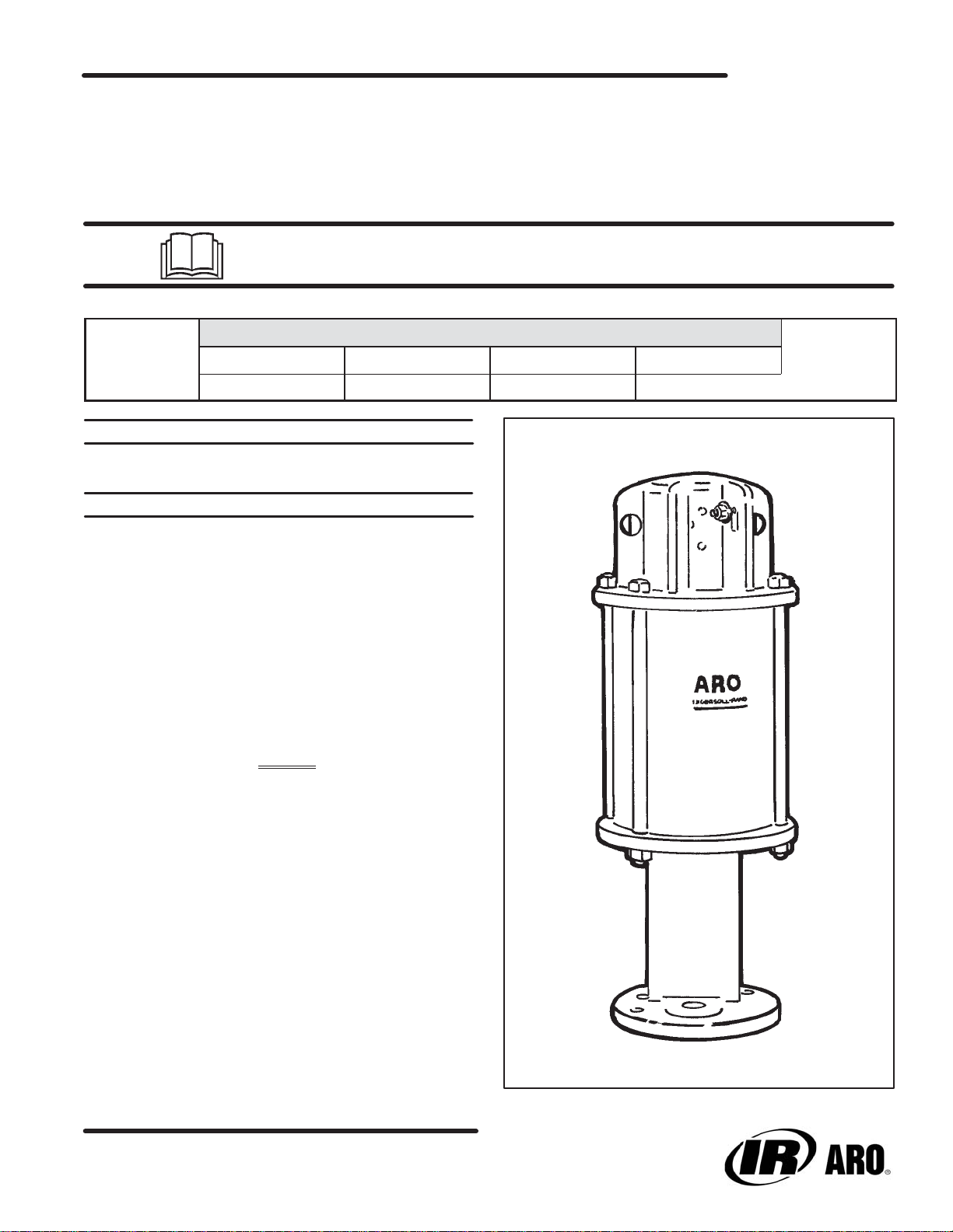
GENERAL DESCRIPTION
The 6" air motor is a general purpose power unit and is used with many
2Ćball, 4Ćball and chop check pumps. It utilizes tie rod type construction
for easy breakdown and it connects to the various lower ends via tie rods
for easy operation. Consult pump model operator's manual for specific
instructions. It is recommended that a muffler be connected to the exĆ
haust port to reduce noise to acceptable OSHA standards.
MODEL
6566X-X
6” STROKE
66620
RELEASED: 8-28-91
REVISED: 10-11-01
(REV. K)
Filtered and oiled air will allow the air motor to operate more efficiently
and yield a longer life to operating parts and mechanisms. A filter capaĆ
ble of filtering particles larger than 50 microns should be used with an
oiler. Keep the oiler supplied with a good grade of S.A.E. no. 90W nonĆ
detergent gear oil, set at a rate not to exceed 1 or 2 drops per minute.
NOTICE
DO NOT OPERATE AIR MOTOR ABOVE RECOMMENDED
AIR PRESSURE OF 150 P.S.I. (10.3 BAR) OR 75 CYCLES PER
MINUTE.
Check model plate.
Air motor may be rated differently in the next assembly.
INGERSOLL-RAND COMPANY
P.O. BOX 151 ONE ARO CENTER BRYAN, OHIO 43506Ć0151
(419) 636-4242 FAX (419) 633-1674
2001 PRINTED IN U.S.A.
Page 2
AIR MOTOR PARTS LIST
PARTS SO MARKED ARE INCLUDED IN 61355 SERVICE KIT.
REF. DESCRIPTION (SIZE IN INCHES) QTY PART NO. REF. DESCRIPTION (SIZE IN INCHES) QTY PART NO.
1 Machine Screw (#8 Ć 32 x 7/8") 4 Y136Ć90ĆS
2 Deflector 1 90409
Deflector (model 65665Ć2B) 1 90409Ć1
3 Screw (#10 Ć 24 x 1/2") 6 95956827
4 Machine Screw (#8 Ć 32 x 3/4") 8 Y19Ć89ĆS
5 Washer 8 90084
6 Machine Screw (1/4" Ć 28 x 3/4") 2 Y119Ć49ĆC
7 Lock Washer (1/4" i.d.) 2 Y14Ć416
8 Air Motor Cap 1 90078
Air Motor Cap (model 65665Ć2B) 1 90078Ć5
9 Valve Guide 1 90488
10 Gasket 1 90083Ć1
11 Valve Plate and Pin Assembly 1 65756
12 Insert Spring Assembly 1 65807
13 Valve Insert 1 99202
14 Valve Plate Gasket 1 90479
15 O" Ring (1/16" x 1Ć3/8" o.d.) 2 Y325Ć26
16 Washer 1 91344
17 O" Ring (1/16" x 7/8" o.d.) 2 Y325Ć18
18 Head Assembly 1 65890
Head Assembly (model 65665Ć2B) 1 65890Ć3
19 U" Cup (3/16" x 1Ć3/8" o.d.) 1 Y186Ć51
20 O" Ring (1/8" x 6" o.d.) 2 Y325Ć256
21 Machine Screw (#8 Ć 32 x 3/8") 4 Y136Ć85ĆS
22 Adapter 1 90111
23 Piston Assembly 1 61419
24 O" Ring (1.191" o.d.) 1 90085
25 Nut 1 90112
26 Valve Rod See chart, page 4
27 Air Cylinder See chart, page 4
28 Tube See chart, page 4
29 O" Ring See chart, page 4
30 Air Motor Base Assembly See chart, page 4
31 Valve Piston 1 92395
32 Valve Plate Gasket 1 90482
33 Valve Plate 1 90480
34 Pilot Insert 1 90487
35 Valve Guide 2 90481
36 Washer 1 90105
37 Upper Gland 1 91006
38 Seal 1 91007
39 O" Ring (.103" x 1.255" o.d.) 1 91207
40 Extension Rod 1 90080
41 Ground Lug 1 93006
42 Piston Adapter 1 92393
43 Lower Gland 1 90114
44 Washer 1 91345
45 O" Ring (1/16" x 7/16" o.d.) 1 Y325Ć11
46 Bolt See chart, page 4
47 Retaining Ring See chart, page 4
48 Guide Washer See chart, page 4
49 U" Cup See chart, page 4
50 Nut See chart, page 4
51 Washer See chart, page 4
52 Piston Rod See chart, page 4
Smart Parts", Keep these items on hand in addition to the service kits for fast repair and reduction of downtime.
DISASSEMBLY OF AIR MOTOR
NOTE: ALL THREADS ARE RIGHT HAND.
1. Force the (23) piston assembly up by pushing the (52) piston rod toĆ
ward the top of the air motor.
2. Remove the four (1) machine screws from the (2) deflector.
3. Remove the (2) deflector.
4. Remove the six (3) screws from the (8) air motor cap.
5. Remove the (8) air motor cap and (10) gasket.
6. Loosen the eight (4) machine screws (which hold the (11) valve plate
and pin assembly, (9) valve guide, two (35) valve guides and the (33)
valve plate) until the (9 and 35) valve guides can be removed by pullĆ
11. Remove the (13) valve insert and the (34) pilot insert.
12. Remove the (32 and 14) gaskets.
13. Remove the (12) insert spring assembly.
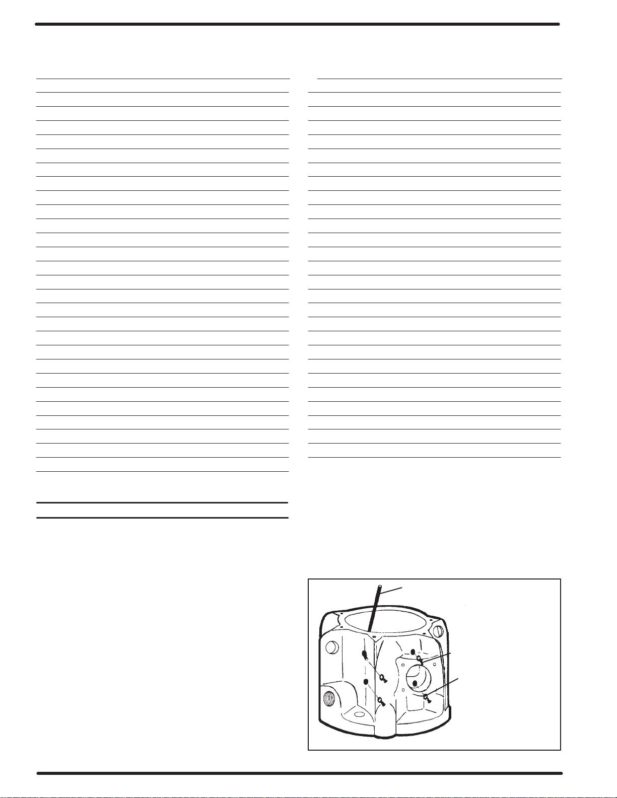
14. Remove the two (6) machine screws and the two (7) lock washers
from the (37) upper gland (see figure 9).
15. Pull the (31) valve piston upward until the (37) upper gland has
pulled out of its chamber.
ALLEN WRENCH
(USE AN ALLEN WRENCH
TO PUSH OUT SCREWS &
WASHERS AS SHOWN.)
ing upward (see figure 9).
7. Remove the eight (4) machine screws and eight (5) washers from
4 SCREWS (8)
the 6" air motor by pressing outward with a small allen wrench (see
figures 1 and 9).
5 WASHERS (8)
8. With a screwdriver, unhook the (12) insert spring assembly from the
bottom of the (11) valve plate and pin assembly.
9. Remove the (12) insert spring assembly from the pins in the top of
the (11) valve plate and pin assembly.
10. Remove the (11) valve plate and pin assembly and (33) valve plate
by pulling upward. If they are stuck, tap the top edge lightly with a soft
FIGURE 1
(THE REMAINING FOUR
WASHERS AND SCREWS
ARE ON THE OPPOSITE
SIDE.)
face hammer or screwdriver handle (do not tap with anything metalĆ
lic).
PAGE 2 OF 8 6564XĆX
Page 3
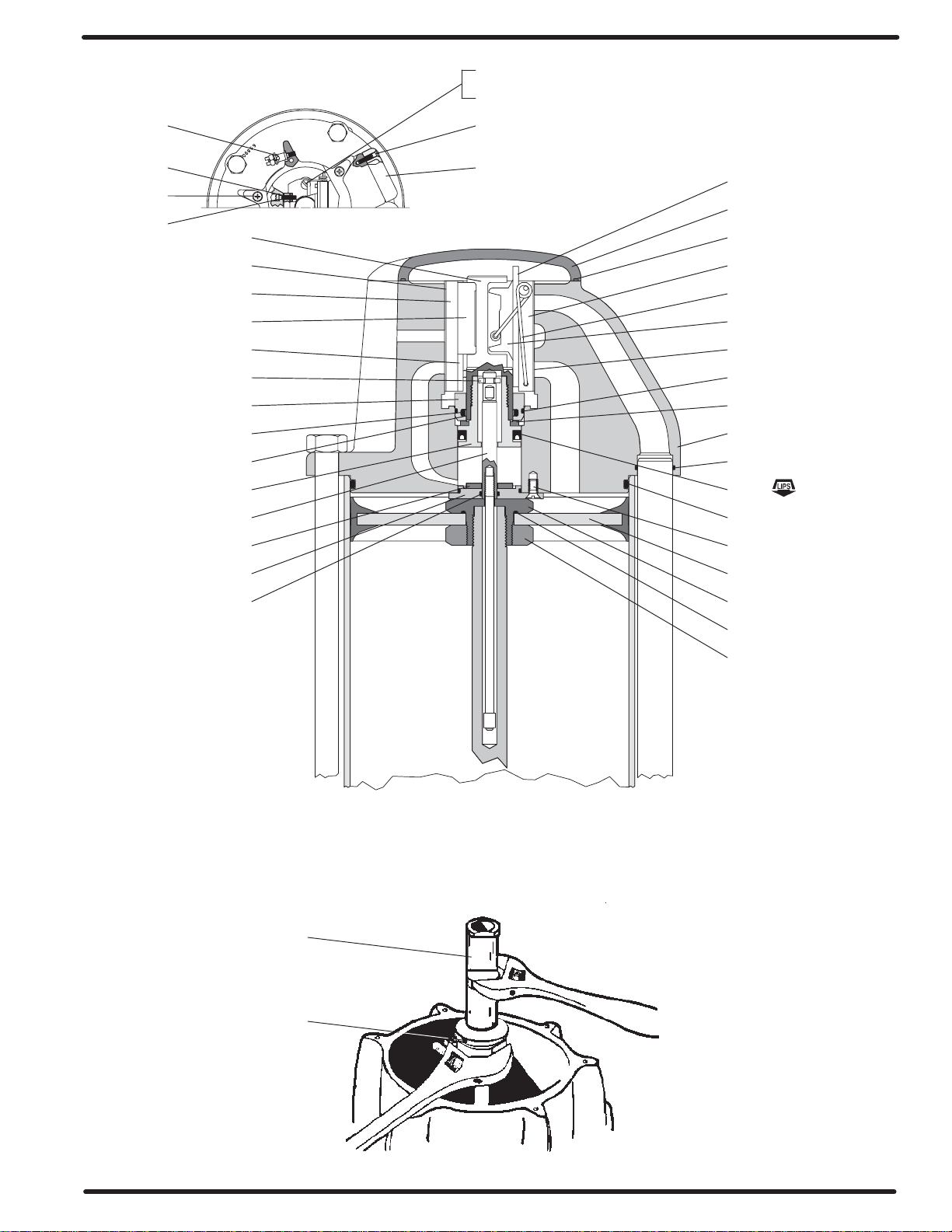
41
6
PART NUMBERS LISTED BELOW AND ON PARTS
7
1
AIR MOTOR HEAD
LIST (OPPOSITE PAGE) ARE TYPICAL.
4
3
5
31
32
33
34
35
36
37
39
38
42
40
44
43
45
2
9
8
10
11
12
13
14
15
16
18
17
19
20
21
23
22
NOTE: LUBRICATE WITH PARKER
‘‘O” RING LUBE (ARO P/N 36460).
31
42
24
25
FIGURE 2
FIGURE 3
PAGE 3 OF 86564XĆX
Page 4

AIR MOTOR PARTS LIST
INDICATES WHERE PARTS ARE USED.
MODELS NO LONGER ACTIVE, SHOWN
FOR REFERENCE ONLY.
ITEM DESCRIPTION PART # (QTY)
26
27
28 Tube 90485Ć1
29
30 Air Motor Base Assembly 65065
46 Bolt (1/2" Ć 20 x 10Ć1/4") 94046Ć1 (4)
47
48
49
50 Nut Y11Ć8ĆC (4)
51
52
Valve Rod 90107Ć1
Valve Rod 90107Ć2
Air Cylinder 90215Ć1
Air Cylinder 90215Ć2
Tube 90485Ć2
O" Ring Y325Ć210
Air Motor Base Assembly 65065Ć2
Air Motor Base Assembly 65067
Air Motor Base Assembly
Bolt (1/2" Ć 20 x 8Ć1/4") 94046Ć2 (4)
Retaining Ring Y147Ć131
Guide Washer 73986
U" Cup Y186Ć16
Washer 90103
Piston Rod 66628
Piston Rod 90082
Piston Rod 90108Ć1
Piston Rod 90108Ć2
65868
AIR MOTOR MODEL NO.
Smart Parts", Keep these items on hand in addition to the service kits for fast repair and reduction of downtime.
INDICATES WHERE
See model plate on (30) base for number.
NOTE: Base styles and lower packings may vary from that shown on
the cover. Refer to model number in the chart above.
PARTS ARE USED.
On model 65662 air motors, a plate is mounted on the bottom of the
(30) base. Therefore, the following parts are different and illustrated on
page 8.
For simplification of ordering and stocking, a Y325Ć210 O" ring and a
Y186Ć16 U" cup will be included in 61355 service kit. When repairing
the motor, use only the one that is needed.
93310 Bushing
93311 Retainer
93312 Guide
All of the service parts are the same for all motors except the lower pisĆ
ton rod packing.
93313 Plate (note the orientation of the plate with the air inlet)
Y6Ć66ĆC Screw (4 req'd)
Y14Ć616ĆC Lock Washer (4 req'd)
NOTE: It is highly recommended that a 90350 installation tool be used.
This will greatly ease installation of (42) piston adapter and piston
valve and will reduce the chances of damage to the (19) U" cup. A
90350 INSTALLATION TOOL
damaged (19) U" cup can usually lead to air motor failure.
PARTS SO MARKED ARE ALSO INĆ
CLUDED IN 61355 SERVICE KIT.
PAGE 4 OF 8 6564XĆX
Page 5

NOTE: LUBRICATE WITH PARKER
‘‘O” RING LUBE (ARO P/N 36460).
AIR MOTOR PISTON ROD AND BASE
SEE CHART ON OPPOSITE PAGE FOR EACH MODEL.
46
20
47
50
51
52
26
27
28
29
17
48 49
30
FIGURE 4
DISASSEMBLY OF AIR MOTOR (CONTINUED)
16. Remove the (37) upper gland.
17. Remove the (38) seal and (39 and 15) O" rings from the (37) upper
gland (see figure 7).
18. Disassemble the (31) valve piston from the (42) piston adapter (see
figure 3).
19. Remove the (31) valve piston.
20. Pull the (42) piston adapter upward and grasp the (40) extension rod
below the (42) piston adapter. Push the (42) piston adapter down on
the (40) extension rod. Remove the (36) washer and (42) piston
adapter.
21. Remove the (16) washer and the (19) U" cup from the (42) piston
adapter.
22. Remove the four (50) nuts from the four (46) bolts.
23. Remove the four (46) bolts.
24. Remove the (18) head assembly and place it on the workbench with
the end that the (28) tube fits in upward".
25. Remove the (20) O" ring from the (18) head assembly.
26. Remove the four (21) machine screws from the (43) lower gland.
27. Remove the (43) lower gland.
28. Remove the (44) washer and (15 and 45) O" rings from the (43) lowĆ
er gland.
29. Remove the (28) tube.
30. Remove the (17) O" ring from the (30) air motor base assembly and
(18) head assembly.
31. Pull upward on the (27) air cylinder until the (52) piston rod is sepaĆ
rated from the (30) air motor base assembly. If the (52) piston rod
does not separate from the (30) air motor base assembly, remove
the (52) piston rod after removal of the (27) air cylinder.
32. Remove the (20) O" ring from the (30) air motor base assembly.
33. Remove the (47) retaining ring, (48) guide washer, (49) U" cup and
(51) washer from the (30) air motor base assembly.
34. Unscrew the (40) extension rod from the (26) valve rod by holding
the (26) valve rod with adjustable type pliers and placing a wrench
on the provided wrench flat at the top of (40) extension rod.
35. Unscrew the (52) piston rod from (22) adapter, using wrench flats on
(52) piston rod. Remove (26) valve rod from (52) piston rod.
NOTE: Caution should be exercised so as not to mar or damage the finĆ
ish on (40) extension rod or (52) piston rod.
36. Remove (25) nut, (23) piston assembly and (24) O" ring from (22)
adapter.
PAGE 5 OF 86564XĆX
Page 6

REASSEMBLY OF AIR MOTOR
NOTE: ALL THREADS ARE RIGHT HAND.
Apply grease to all O" rings, U" cups and other rubber goods when
installing.
1. Slip the (24) O" ring on the (22) adapter, clean with solvent and apĆ
ply Loctite 271 to the external threads of the (22) adapter. Assemble
the (22) adapter and (25) nut to the (23) piston assembly and tighten
to 160 Ć 180 ft lbs.
2. Put the threaded end of the (26) valve rod thru the hole in the (22)
adapter, with the machined shoulder" end of the (26) valve rod on
the threaded side of the (22) adapter.
3. While holding the (26) valve rod below the threads with locking pliĆ
ers, clean with solvent and apply Loctite 271 to the threads and atĆ
tach the (40) extension rod, using the provided wrench flats.
4. Place the machined shoulder" end of the (26) valve rod into the hole
in the end of the (52) piston rod and assemble (52) piston rod to (22)
adapter, tightening using a wrench on flats provided.
5. Thoroughly grease and install the (20) O" ring in the (30) air motor
base assembly.
6. Grease and place the (51) washer and (49) U" cup into the (30) air
motor base assembly. Place the (48) guide washer and (47) retainĆ
ing ring in the (30) air motor base assembly.
7. Grease and install (15) O" ring on the (43) lower gland.
8. Grease the bore in the (18) head assembly and insert the (43) lower
gland into the bore of the (18) head assembly, using a twisting moĆ
tion.
9. Align the screw holes in the (43) lower gland and (18) head assembly.
10. Secure the (43) lower gland to the (18) head assembly using four
(21) machine screws.
11. Put the (52) piston rod thru the (49) U" cup in the (30) air motor base
assembly, being careful not to damage the U" cup.
12. Thoroughly grease the inside of the (27) air cylinder.
27 CYLINDER (APPLY
GREASE THROUGHOUT
INSIDE)
13. Fill the area between the lips of (23) piston assembly with grease,
then insert into the bottom of the (27) air cylinder (see figure 3).
14. Push the (23) piston assembly to the top of the (27) air cylinder.
15. Thoroughly grease and install the (45 and 20) O" rings into the (18)
head assembly.
16. Thoroughly grease the two (17) O" rings and install one in the (30)
air motor base assembly. Install the other in the (18) head assembly.
17. Press the (28) tube into the counterbored hole in the (30) air motor
base assembly.
18. Push the (40) extension rod thru the (45) O" ring in the base of the
(18) head assembly.
19. Press the (18) head assembly down until the (27) air cylinder and
(28) tube are seated in the (18) head assembly.
20. Insert the four (46) bolts down thru the holes in the flanges of the (18)
head assembly and the (30) air motor base assembly.
21. Screw the four (50) nuts on the four (46) bolts. Alternately and evenly
tighten the nuts.
22. Thoroughly grease and install the (19) U" cup in the (42) piston
adapter, with the lips of the (19) U" cup down toward the thick flange
on the (42) piston adapter.
23. Thoroughly grease and install the (39 and 15) O" rings in the (37)
upper gland.
24. Bend the (38) seal in a heart shape and install in the (37) upper gland
inside the (39) O" ring (see figure 6).
SEAL FREE FORM SEAL COLLAPSED FORM
PUSH SIDES IN, AS SHOWN, THEN SLIDE INTO BORE AND POSIĆ
TION SEAL IN GROOVE.
FIGURE 6
25. Grease and carefully push the (31) valve piston into the (37) upper
gland to size the (38) seal, then remove (see figure 7 below).
15 ``O" RING
23 PISTON
(APPLY GREASE
AROUND EDGE)
52 PISTON ROD
39 ``O" RING
38 SEAL
DIRECTION FOR SIZING
31 VALVE PISTON
37 UPPER GLAND
FIGURE 7
26. Place the (44) washer over the (40) extension rod.
27. Pull the (40) extension rod up and grasp with two fingers (see figure 8).
28. Place the 90350 installation tool over the (40) extension rod, with the
turned diameter down and the chamfer up.
29. Fit the turned diameter of the 90350 installation tool into the bore in
the bottom of the (18) head assembly.
30. Place the (42) piston adapter down over the (40) extension rod, with
the threads up.
31. Insert the (36) washer into the groove in the top of the (40) extension
rod.
FIGURE 5
PAGE 6 OF 8 6564XĆX
Page 7

36 WASHER GROOVE
40 EXTENSION ROD
FIGURE 8
32. Pull the (42) piston adapter up around the (36) washer.
33. Place the (16) washer over the (40) extension rod and into the (42)
piston adapter.
34. Clean with solvent and put Loctite 271 on the threads of the (31)
valve piston. Screw the (31) valve piston into the (42) piston adapter
and tighten (see figure 3).
35. Push the assembled (42) piston adapter and (31) valve piston down
thru the 90350 installation tool until they bottom.
36. Remove the 90350 installation tool.
37. Install the (37) upper gland over the (31) valve piston and push
down, being careful to retain the (38) seal in the O" ring groove.
38. Align the two bolt holes and secure the (37) upper gland to the (18)
head assembly with the two (6) machine screws and two (7) lock
washers (see figure 9).
39. Insert the (12) insert spring assembly in the (18) head assembly,
with the hooks down and the nylon roller toward the (31) valve piston
(see figures 2 and 9).
40. Thoroughly grease and insert the (34) pilot insert, two (35) valve
guides, (33) valve plate and (32) gasket into the (18) head assembly
(see figure 9).
41. Thoroughly grease and insert the (13) valve insert into the (18) head
assembly (see figure 2).
42. Thoroughly grease and insert the (14) gasket and the (11) valve
plate and pin assembly between the (13) valve insert and the (18)
head assembly, with the two pins in the (11) valve plate and pin asĆ
sembly up (see figures 2 and 9).
43. Hook the round coils in the (12) insert spring assembly over the pins
in the (11) valve plate and pin assembly (see figure 9).
44. Hook the bottoms of the (12) insert spring assembly into the holes on
the side of the (11) valve plate and pin assembly.
45. Insert the (9) valve guide against the face of the (11) valve plate and
pin assembly. The legs of the (9) valve guide should be down, with
the leg having the threaded hole the farthest from the bottom toward
the air inlet in the (18) head assembly.
46. Insert and tighten across corners of eight (4) machine screws and
eight (5) washers (see figures 1 and 9).
47. Thoroughly grease and install the (10) gasket in the (8) air motor
cap.
48. Place the (8) air motor cap on the (18) head assembly and secure
with the six (3) screws (see figure 2).
49. Place the (2) deflector on exhaust port of the (18) head assembly,
with the opening down, and secure with four (1) machine screws
(see figure 2).
4 SCREW (8)
5 WASHER (8)
32 GASKET
33 VALVE PLATE
35 VALVE GUIDE (2)
37 UPPER GLAND
6 SCREW (2)
7 LOCK WASHER (2)
12 SPRING ASS'Y
9 VALVE GUIDE
11 VALVE PLATE
14 GASKET
18 HEAD ASSEMBLY
FIGURE 9
PROBLEM
Air leakage out of main exhaust.
CAUSE
Worn (13) valve insert.
REMEDY
Replace (13) valve insert.
CAUSE
Worn (11) valve plate and pin assembly.
REMEDY
Replace (11) valve plate and pin assembly.
CAUSE
Damaged (23) piston assembly.
REMEDY
Replace (23) piston assembly.
TROUBLE SHOOTING
PROBLEM
Continual air leakage out of bleeder hole in (18) head assembly.
CAUSE
Worn (15) O" ring or (38) seal.
REMEDY
Replace (15) O" ring and (38) seal.
PROBLEM
Air leakage around (52) piston rod.
CAUSE
Worn (49) U" cup.
REMEDY
Replace (49) U" cup.
PAGE 7 OF 86564XĆX
Page 8

65662 AIR MOTOR PISTON ROD & BASE
90108-1 Piston Rod
65868 Air Motor Base
Ass’y. (Stub)
93312 Guide
93313 Plate
ITEM 52 PISTON ROD END VARIETY
Y325-210 “O” Ring
93310 Bushing
93311 Retainer
Y6-66-C
Screw (4 req’d)
Y14-616-C
Lock Washer (4 req’d)
66628 Piston Rod 90082 Piston Rod90108-1 Piston Rod
90108-2 Piston Rod
P/N 97999Ć174
PAGE 8 OF 8 6564XĆX
 Loading...