

Page 1
OPERAT
OR’S MANUAL
INCLUDING: OPERATION, INSTALLATION & MAINTENANCE
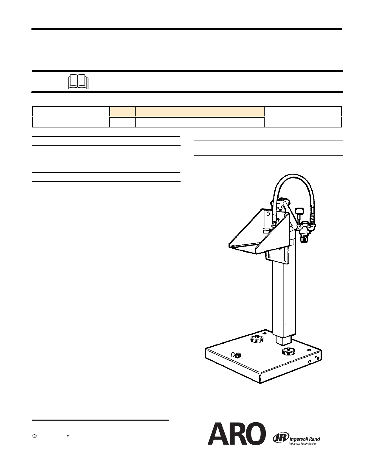
SINGLE POST LIFT/RAM
For use with 5 Gallon Drums (T apered or Straight)
651615–X
RELEASED:
REVISED: 6–21–10
2–25–95
(REV. C)
READ THIS MANUAL CAREFULL
OPERA
THIS MANUAL COVERS THE FOLLOWING MODELS
MODEL TYPICAL PUMP APPLICATION
651615 3'' & 4-1/4'' AIR MOTORS (TIE ROD PUMPS)
TING OR SER
SERVICE KITS
Rebuild Kit for E512LM Valve - 116722
Repair Kit for 127112-000 Miniature Regulator - 104158
GENERAL
The ARO Model 651615-X Single Post Lift/Ram uses a 3-1/2'' airpowered cylinder which is welded to a heavy gauge base base. It is norĆ
mally used to raise and lower a fluid handling pump and follower in and
out of of standard 5-gallon drum or when used as a ram it can force
high viscosity flowable material into the pump inlet.
When properly secured, this unit has the ability to raise a pump to clear
a standard 5-gallon drum. The operator is then able to easily remove
the pump from a pail.
This Lift/Ram uses a hand lever 4-way control valve which controls the
air necessary to raise and lower the lift. This unit includes an auxiliary
manual air valve which is used to supply a controlled amount of air
pressure to the bottom of the follower plate. When the Control Valve is
in the ``UP'' position a small amount of air pressure applied under the
follower plate will help to raise the follower plate, pump and lift by reĆ
lieving the vacuum. See Page 3.
DESCRIPTION
Y BEFORE INST
VICING THIS EQUIPMENT
BASE DIMENSIONS: 20'' SQUARE (508 mm)
HEIGHT: LOWERED 36-3/4'' (.9m), RAISED 56-1/4'' (1.7 m)
ALLING,
.
INGERSOLL RAND COMPANY LTD
209 NORTH MAIN STREET – BRYAN, OHIO 43506
(800) 495-0276 FAX (800) 892-6276
www.ingersollrandproducts.com
© 2010
651615
SINGLE POST LIFT
Page 2
OPERATING
AND SAFETY PRECAUTIONS
Z Read and heed all Warnings, Cautions, and Safety PrecauĆ
tions before operating.
Z Use only genuine ARO replacement parts to assure compatĆ
ible pressure rating and longest service life.
Shock hazard.
Striking electrical
fixtures can cause
injury.
WARNING PREVENT ELECTRIC SHOCK. Be certain the
area above the lift is clear of electrical fixtures, devices and
wiring. Examine the working area and take necessary action to asĆ
sure adequate clearance for the lift and pump assembly to raise to
the fullest limit and function properly.
Pinch hazard.
Follower can descend
quickly causing injury
WARNING PINCH HAZARD. Follower can descend quickly,
causing injury. Keep hands clear when aligning with containĆ
er. In the raising and lowering function the lift could get hung up or
the descent could be temporarily restricted. The lift could in some
Keep the area
overhead clear of
electrical devices.
Keep hands clear
when aligning with
container
.
situations drop suddenly and be hazardous. If the follower plate
does not enter the drum properly, DO NOT ATTEMPT TO REĆ
POSITION IT WITH YOUR HANDS; release the downward presĆ
sure, raise the lift, realign the drum and restart.
WARNING STAND CLEAR. When raising or lowering the lift
keep clear and operate from a safe position.
Hazardous pressure.
Can result in injury or
property damage.
Do not exceed maxi
mum inlet air pressure.
-
WARNING HAZARDOUS PRESSURE. Do not exceed maxiĆ
mum inlet air pressureof 160 psi(11 bar).Operating lift at higher
pressure may cause lift damage and/or personal injury and/or
property damage. Do not service or clean pump, hoses or dispensĆ
ing valve while the system is pressurized.
WARNING DO NOT EXCEED DRUM PRESSURE LIMITS.
Know the pressure limitations of the drum and regulate the air presĆ
sure within safe limits when supplying air follower plate.
CAUTION Be certain all operators of this equipment have
been trained for safeworking practices,understand it's limitaĆ
tions, and wear their safety goggles/equipment as required.
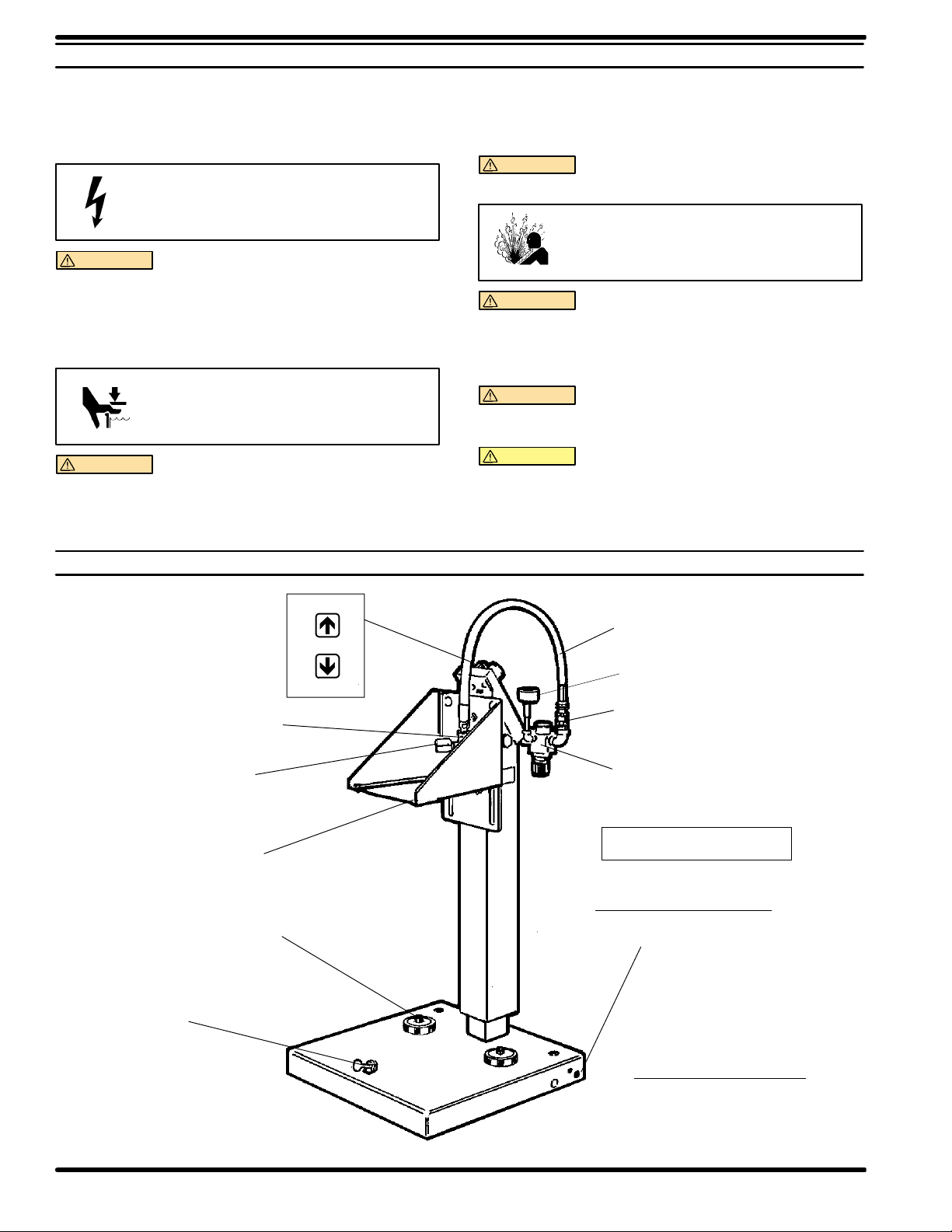
FIGURE 1
THUMB
SCREW
Y43-4-C
STREET ELBOW
Y167-5
ADAPTER
(1/4 NPT X 1/2 NPT)
MOUNTING
BRACKET
(See Page 8)
DRUM STOP
UP
NEUTRAL
DOWN
MAJOR COMPONENTS
622553-2
AIR HOSE
(1/2 NPT(M) X 1/2 NPT(M) )
GAUGE
75366
SWIVEL
PUMP AIR
MANIFOLD
Maximum Inlet Air Pressure
160 PSI (11 bar)
Optional Items Available
PORTABILITY KIT
66713 (See Page 8)
Included but not shown
Fasteners used to mount pump
to mounting plate.
Four Y6-63-C Screws
Four Y13-6-C Washers
651615-XPAGE 2 OF 8
Page 3
LIFT/RAM INSTALLATION
WARNING Failure to properly install the lift assembly can
result in severe personal injury and property damage. Read
the warning on page 2.
1. Establish the desired location for the lift/ram and pay special attenĆ
tion to work area above, this area above the lift must be open, withĆ
out obstructions and safely away from any electrical devices.
2. Place the pump on the follower plate and align the pump and folĆ
lower plate on the base and assemble pump to the mounting brackĆ
et on the ram.
OPERATING INSTRUCTIONS
OPERATING INSTRUCTIONS / INITIAL SETUP PROCEDURE
WARNING STAND CLEAR. When raising or lowering the
lift. Read the warning on page 2.
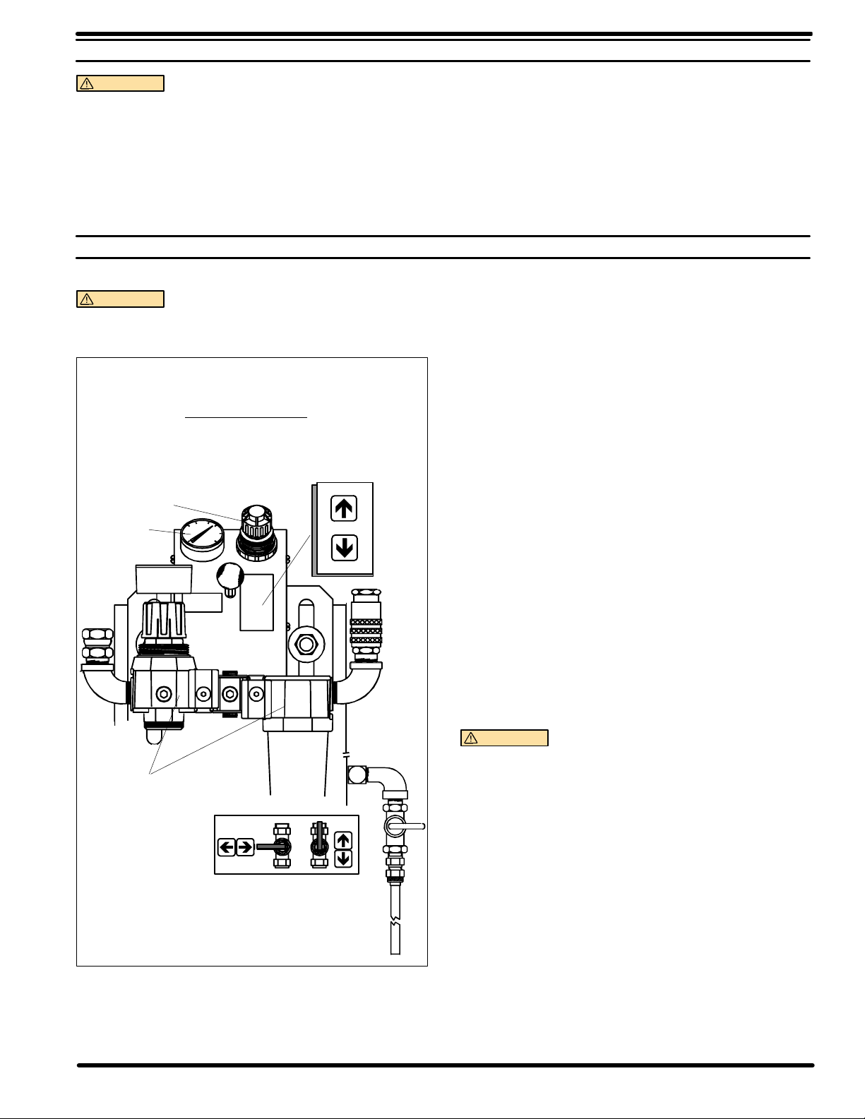
AIR CONTROLS
CONTROL
LEVER
PRESSURE
REGULATOR
GAUGE
UP
NEUTRAL
DOWN
3. Assemble air hose to air motor inlet.
4. Install the check and follower plate air hose from the Control Valve.
5. Assemble the vent plug to the follower plate.
NOTE: The ram was tested at the factory. The unit should be generally
checked over for leakage because the fittings on the system may have
loosened in shipment.
TO RAISE LIFT, (THE FIRST TIME):
1. Take note of the pump/drum clearance above. Be certain the lift is
clear of any objects above. Also refer to OPERATING AND SAFEĆ
TY PRECAUTIONS found on page 2.
2. Connect the air supply (160 PSI MAX) to the air inlet.
3. Shift the control valve lever to the ``UP'' position.
4. Raise the lift high enough to clear the height of the drum. Stop the
lift upward travel by moving the control valve lever to the (center)
``NEUTRAL'' position.
TO RAISE LIFT, (NORMAL OPERATION):
1. Adjust the Follower Plate Air Valve pressure up to approximately 8
psig. DO NO OVERPRESSURIZE THE DRUM to avoid damage.
NOTE: Air from this valve will only pass when the Control Lever is
in the ``UP'' position.
2. Shift the control valve lever to the ``UP'' position.
3. Raise the lift high enough to clear the height of the drum. Stop the
lift upward travel by moving the control valve lever to the (center)
``NEUTRAL'' position.
PUMP
FILTER-REGULATOR
OFF
FOLLOWER PLATE
AIR SUPPLY VALVE
FIGURE 2
ON
TO CHANGE DRUM:
NOTE: The Control Lever should be in the ``NEUTRAL'' position.
1. Place a new drum into position.
TO LOWER LIFT:
WARNING PINCH HAZARD. Follower can descend quickly
causing injury. Keep hands clear when aligning with containĆ
er. Read the warning on page 2.
NOTE: Be certain the Follower Plate vent plug has been removed so
that the air trapped between the follower and the material is allowed to
escape from this vent. Captured air between the follower plate and
drum will escape.
NOTE: The lift may hesitate momentarily before starting downward,
the air pressure inside the post air chamber must decrease before it will
begin to descend.
1. Shift the control valve lever to the ``DOWN'' position and proceed to
lower the pump.
2. Replace the vent plug once the material begins to ooze from the
vent opening.
651615-X
PAGE 3 OF 8
Page 4

PARTS LIST
Single Post Ram/Lift
ITEM DESCRIPTION (SIZE IN INCHES)
1 Gauge (1) 29975
2 Tube 5" (1) 44632 j
3 Tube 4.75" (4) 44632 j
4 Screw (1/4-20) (3) Y99-45-C
5 Nut (1/4-20) (3) Y12-4-C
6 Washer (1/4") (3) Y13-4-C
7 Screw (5/8-11) (2) Y6-105-C
8 Lockwasher (5/8) (2) Y14-625-C
9 Manifold (1) 92380
10 Panel Nut (1) 29661
11 Connector (7) 59688-4
12 Elbow (1/8" NPT) (1) Y43-1-C
13 Shut-off Valve (1) Y28-2
14 Connector (1) Y214-2
15 Tube 2.208 feet (1) 59675 f
16 Regulator (1) R27241-100
17 1/2" Male Swivel (1) 75366
18 Elbow (1/2) (2) Y43-4-C
(QTY)
PART NO.
ITEM DESCRIPTION (SIZE IN INCHES) (QTY) PART NO.
19 Carriage Bolt (1/2-13) (4) Y84-801-C
20 Lockwasher (1/2') (4) Y14-816-C
21 Washer (1/2") (4) Y13-8-C
22 Nut (1/2-13) (4) Y12-8-C
23 Cover (1) 92375
24 Self Tapping Screw (#8-32) (4) Y222-130-C
25 Label (1) 92449
26 Coupler (1) 23103-004
27 Connector (1/2 NPT) (1) 23903-410
28 Filter (1) F25241-100
29 Manifold Kit (1) 104170
j Bulk Tube-100 Ft.Roll 3/16" O.D.- 59690-104
f Bulk Tube-100 Ft.Roll 1/4" O.D.- 59675-100
l Apply Tape to threads.
Z Apply Anaerobic Pipe Thread Sealant to threads.
PTFE
651615-XPAGE 4 OF 8
Page 5

l1
BASIC SINGLE POST RAM/LIFT
10
ASM.
2
3
4
5
6
7
8
9
47
11
3
11
3
11
53
12
13
14
15
FIGURE 3
l17
l18
19
20
21
22
16
23
24
25
26
27l
18l
FIGURE 4
28
29
651615-X
PAGE 5 OF 8
Page 6

PARTS LIST
Single Post Ram/Lift
ITEM DESCRIPTION (SIZE IN INCHES)
30 Thumb Screw (1) Y66-378-C
31 Base (1) 66558
32 Bucket Stop (2) 92565
33 Carriage Bolt (2) Y84-601-C
34 Nut (3/8-6) (2) Y12-6-C
35 Lockwasher (2) Y14-616-C
36 Tube (1) 92378
37 Rod (1) 92379
38 ``O" Ring (3 1/4" O.D.) (1) Y325-336
39 Retaining Ring (1) 90503
40 Plate (1) 91396
41 Screw (4) Y6-42-C
42 Nut (1/4-20) (4) Y12-4-C
43 Washer (1/4") (4) Y13-4-C
44 Bracket (1) 93968
45 Male Fitting (3) 59753-4
46 Elbow (3) 92388
47 ``E" Series 4-Way Valve g (1) E512LM
48 Adapter (3) 6045
49 Plug (1/8" NPT) (1) Y17-50
50 Washer (1) Y13-6-C
51 Spring (1) 38226
(QTY)
PART NO.
ITEM DESCRIPTION (SIZE IN INCHES)
52 Air Regulator (1) 127122-000
53 Hose Coupling (1) 3249
54 Male Tee Fitting (2) 59747-4
55 Tubing 5.37 (1) 44632j
56 Plug (1) 92389
57 ``O" Ring (7/8" O.D.) (1) Y325-18
58 Gauge (1) 100067
59 Coupling (1/4 NPT) (1) Y43-42-C
60 Nipple (1/4 NPT) (1) Y44-11-C
61 Elbow (1/4 NPT) (1) Y43-2-C
62 Nipple (1/4 NPT) (1) Y44-13-C
63 Retaining Ring (1) Y147-200
64 Retaining Washer (1) 90509
65 Retaining Wiper (1) 90508
66 Retaining Washer (1) 90511
67 Unipack Seal (1) 90507
68 Dowel Pin (1) Y148-35
69 Cap & Bearing (1) 66643
70 Column (1) 66557
71 Piston (1) 92376
72 Packing (2) 90506
g Repair kit for Valve E512LM 116722
l Apply Tape to threads.
Z Apply Anaerobic Pipe Thread Sealant to threads.
PTFE
(QTY)
PART NO.
651615-XPAGE 6 OF 8
Page 7

BASIC SINGLE POST RAM/LIFT ASM.
44
46
11
47
l48
45
Z
49
50
51
52
53
54
55
56
67
57
66
58l
59l
60l
61l
62
63
64
65
Z
30
43
42
41
31
40
33
32
34
35
39
38
37
36
68
69
70
Z
71
72
651615-X
FIGURE 5
PAGE 7 OF 8
Page 8

DIMENSIONAL
DA
TA
91396 MOUNTING PLATE
8-3/4"
SQUARE
4-3/8"
5"
1 3/4"
3-1/2"
Material-11 Gauge Steel
66713 PORTABILITY KIT
FIGURE 6
FIGURE 7
PN 97999-604
651615-XPAGE 8 OF 8
 Loading...