

Page 1

IMPORTANT SAFETY INFORMATION ENCLOSED - SAVE THESE INSTRUCTIONS
READ AND UNDERSTAND THIS MANUAL BEFORE OPERATING THIS PRODUCT
IT IS YOUR RESPONSIBILITY TO MAKE THIS SAFETY INFORMATION
AVAILABLE TO OTHERS THAT WILL OPERATE THIS PRODUCT
FAILURE TO OBSERVE THE FOLLOWING WARNINGS COULD
RESULT IN INJURY
Refer all communications to the nearest Ingersoll-Rand
Office or Distributor
© Ingersoll-Rand Company 2002
Printed in Japan
• Always install, operate, inspect and maintain this product
in accordance with all applicable standards and
regulations (local, state, country, federal, etc.).
• Always use clean, dry air at 90 psig (6.2 bar/620 kPa)
maximum air pressure at the inlet. Higher pressure may
result in hazardous situations including excessive speed,
rupture, or incorrect output torque or force.
• Be sure all hoses and fittings are the correct size and are
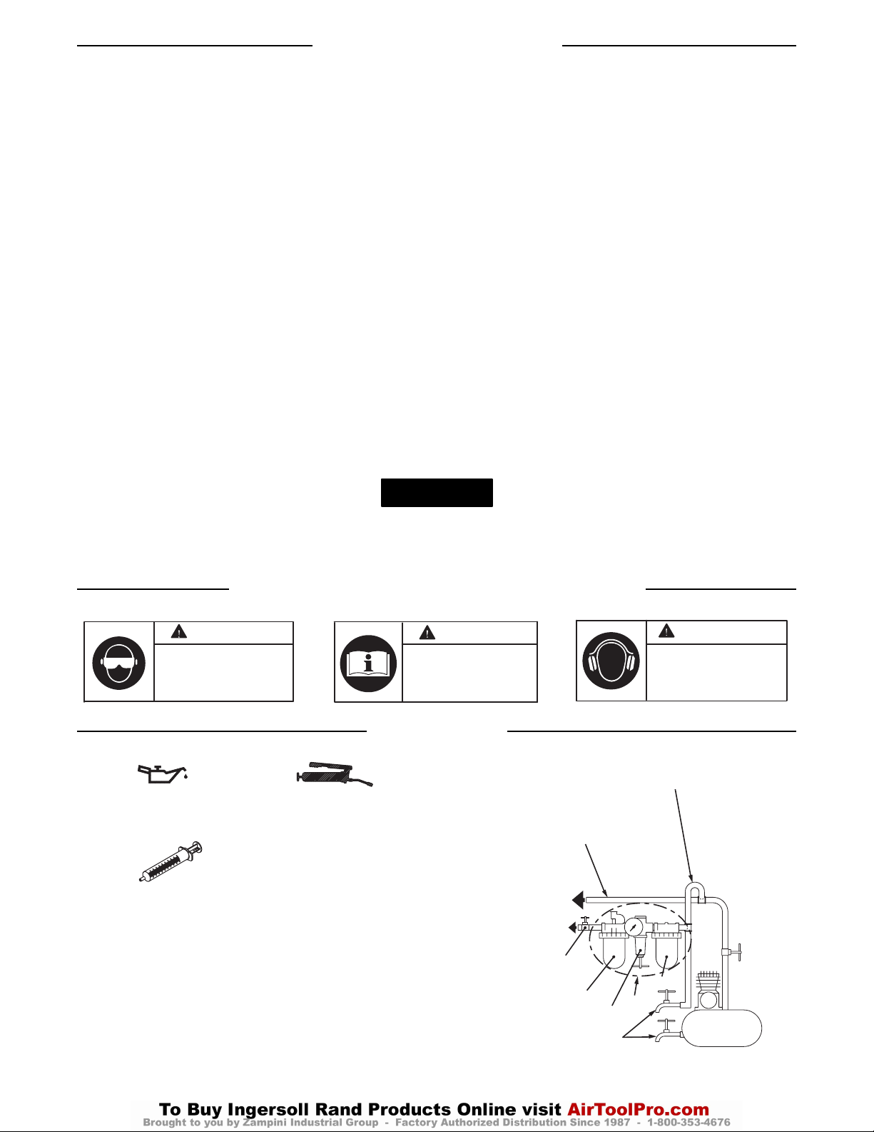
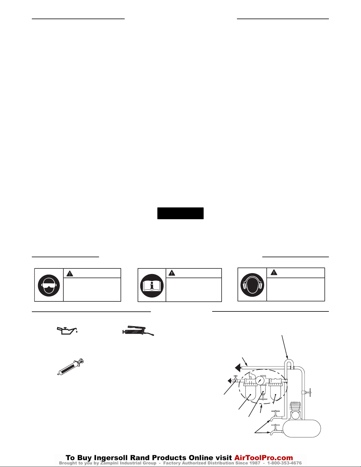
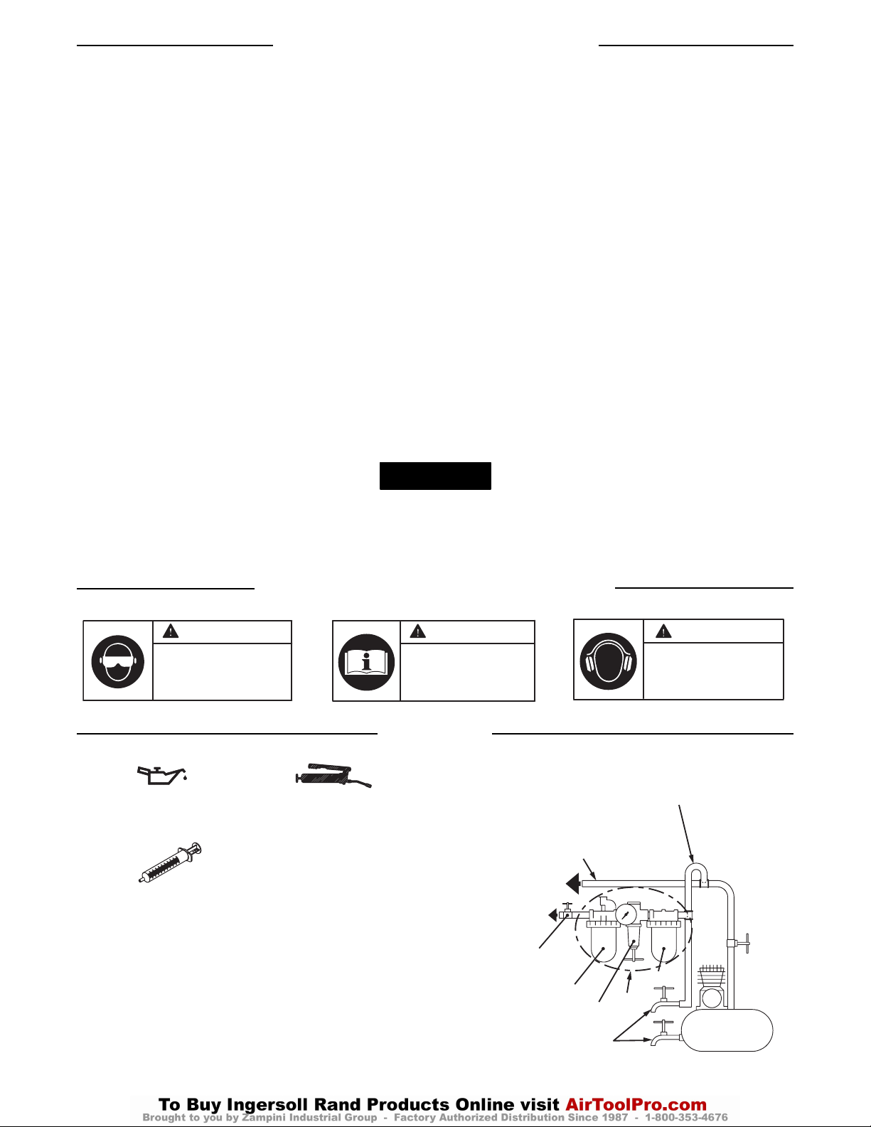
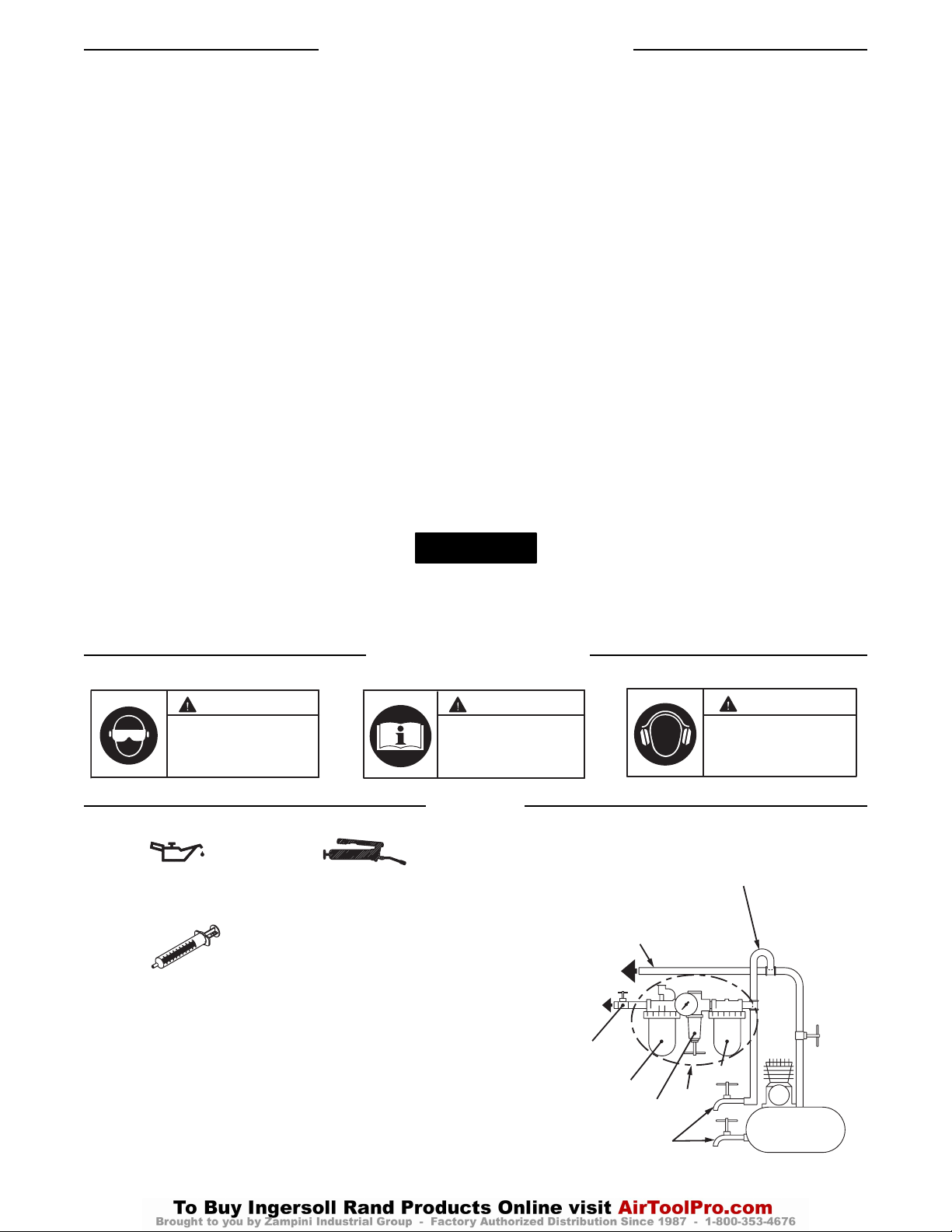
tightly secured. See Dwg. TPD905-2 for a typical piping
arrangement.
• Ensure an accessible emergency shut off valve has been
installed in the air supply line, and make others aware of
its location.
• Do not use damaged, frayed or deteriorated air hoses and
fittings.
• Keep clear of whipping air hoses. Shut off the compressed
air before approaching a whipping hose.
• Always turn off the air supply and disconnect the air
supply hose before installing, removing or adjusting any
accessory on this tool, or before performing any
maintenance on this tool.
• Do not lubricate tools with flammable or volatile liquids
such as kerosene, diesel or jet fuel. Use only recommended
lubricants.
• Keep work area clean, uncluttered, ventilated and
illuminated.
• Do not remove any labels. Replace any damaged label.
04578084
Form P7528
Edition 3
June, 2002
OPERATION AND MAINTENANCE MANUAL FOR
MODELS 40PSQ1, 45PS3, 45PSQ1, 55PS3, 55PSQ1, 70PS3 AND 90PS4
TWIN BLADE SHUTOFF IMPULSE WRENCHES
Models 40PSQ1, 45PS3, 45PSQ1, 55PS3, 55PSQ1, 70PS3 and 90PS4 Impulse Wrenches are
designed for assembly operations which require high speed rundown of fasteners with consistent
torque delivery and reduced torque reaction.
PLACING TOOL IN SERVICE
• Always wear eye protection when operating or performing
maintenance on this tool.
• Always wear hearing protection when operating this tool.
• Always use Personal Protective Equipment appropriate to
the tool used and material worked. This may include dust
mask or other breathing apparatus, safety glasses, ear
plugs, gloves, apron, safety shoes, hard hat and other
equipment.
• This tool is not designed for working in explosive
environments, including those caused by fumes and dust, or
near flammable materials.
• This tool is not insulated against electric shock.
• Be aware of buried, hidden or other hazards in your work
environment. Do not contact or damage cords, conduits,
pipes or hoses that may contain electrical wires, explosive
gases or harmful liquids.
• Keep others a safe distance from your work area, or ensure
they use appropriate Personal Protective Equipment.
• Keep hands, loose clothing, long hair and jewelry away
from working end of tool.
GB
USING THE TOOL
Page 2

2
WARNING SYMBOL IDENTIFICATION
Ingersoll-Rand No. 50 Ingersoll-Rand No. 68
Ingersoll-Rand Fluid Part
No. EQ106S-400-1
After each 20 000 cycles, or as experience indicates, drain
and refill the Impulse Unit Drive Assembly as instructed
in this manual using the Fluid Replacement Kit (Part
No. EQ106S-K400). Lubricate the hex drive and the output
shaft before assembly.
(Dwg. TPD905-2)
Using the Tool (Continued)
• Prevent exposure and breathing of harmful dust and
particles created by power tool use.
Some dust created by power sanding, sawing, grinding,
drilling, and other construction activities contains
chemicals known to cause cancer, birth defects or other
reproductive harm. Some examples of these chemicals
are:
- lead from lead based paints,
- crystalline silica from bricks and cement and other
masonry products, and
- arsenic and chromium from chemically treated
lumber.
Your risk from these exposures varies, depending on
how often you do this type of work. To reduce your
exposure to these chemicals: work in a well ventilated
area, and work with approved safety equipment, such
as those dust masks that are specially designed to filter
out microscopic particles.
• Power tools can vibrate in use. Vibration, repetitive motions
or uncomfortable positions may be harmful to your hands
and arms. Stop using any tool if discomfort, tingling feeling
or pain occurs. Seek medical advice before resuming use.
• Keep body stance balanced and firm. Do not overreach
when operating this tool. Anticipate and be alert for sudden
changes in motion, reaction torques, or forces during start
up and operation.
• Tool and/or accessories may briefly continue their motion
after throttle is released.
• To avoid accidental starting - ensure tool is in “off” position
before applying air pressure, avoid throttle when carrying,
and release throttle with loss of air.
• Ensure work pieces are secure. Use clamps or vises to hold
work piece whenever possible.
• Do not carry or drag the tool by the hose.
• Do not use power tools when tired, or under the influence
of medication, drugs, or alcohol.
• Never use a damaged or malfunctioning tool or accessory.
• Do not modify the tool, safety devices, or accessories.
• Do not use this product for purposes other than those
recommended.
• Use accessories recommended by Ingersoll-Rand.
• For reversible models, note the position of the reversing
mechanism before operating the tool so as to be aware of
the direction of rotation when operating the throttle.
• Use only impact sockets and accessories. Do not use hand
(chrome) sockets or accessories.
• Periodically check the drive end of the tool to make certain
that the socket retainer functions correctly, and that sockets
and drive ends are not excessively worn which may allow
the socket to come off when rotating.
LUBRICATION
The use of other than genuine Ingersoll-Rand replacement parts may result in safety hazards, decreased tool performance, and
increased maintenance, and may invalidate all warranties.
Repairs should be made only by authorized trained personnel. Consult your nearest Ingersoll-Rand Authorized Servicenter.
WARNING
Always wear eye protection
when operating or performing
maintenance on this tool.
WARNING
Read this manual before
operating tool.
WARNING
Always wear hearing
protection when operating
this
tool.
Branch Line(s) Inner Ø
to be 2X Size of
Air Tool’s Inlet Ø
F
Filter
Compressor
Main Line(s) Inner Ø
to be 3X Size of
Air Tool’s Inlet Ø
To Air
System
To Air
Tool
Emergency
Shut-Off
Valve
Lubricator
Drain Regularly
L
Regulator
R
FRL
Page 3

3
Torque Adjustment
To adjust the torque on these Twin Blade Impulse
Wrenches, proceed as follows:
1. Remove the Socket Plug.
2. Rotate the Drive Shaft until the Torque Adjustment
Screw is visible in the opening. (There is colored paint
in the head of the Torque Adjustment Screw.)
3. Using a 1.5 mm hex wrench, rotate the Torque
Adjustment Screw clockwise to increase torque. To
decrease torque, rotate the Torque Adjustment Screw
counter-clockwise. Do not rotate the Oil Plug.
4. Replace the Socket Plug.
Make all final adjustments at the job.
Tested in accordance with PNEUROP PN8NTC1.2
Tested in accordance with ISO8662
ADJUSTMENTS
Model Sound Level Vibration
dB(A) Level
Pressure Power m/s
2
40PSQ1 74.4 --- 0.8
45PS3 80.3 --- 0.5
45PSQ1 80.3 --- 0.5
55PS3 81.3 --- 0.7
55PSQ1 81.3 --- 0.7
70PS3 82.7 --- 0.8
90PS4 92.8 --- 1.6
Page 4
4
DECLARATION OF CONFORMITY
(F) CERTIFICAT DE CONFORMITÉ (D) KONFORMITÄTSERKLÄRUNG (I) DICHIARAZIONE DI CONFORMITÀ
(E) DECLARACIÓN DE CONFORMIDAD (NL) SCHRIFTELIJKE VERKLARING VAN CONFORMITEIT
(DK) FABRIKATIONSERKLÆRING (S) FÖRSÄKRAN OM ÖVERENSSTÄMMELSE
(N) KONFORMITETSERKLÆRING (FIN) VAKUUTUS NORMIEN TÄYTTÄMISESTÄ (P) DECLARAÇÃO DE
CONFORMIDADE
Supplier’s Name: Address:
Ingersoll-Rand Swan Lane, Hindley Green, Wigan WN2 4EZ
(F) nom du fournisseur (DK) naam leverancier
(D) Name des Herstellers (S) leverantörens namn
(I) nome del fornitore (N) leverandørens navn
(E) nombre del proveedor (FIN) Toimittajan nimi
(NL) naam leverancier (P) nome do fornecedor
(F) adresse (DK) adresse
(D) Adresse (S) adress
(I) indirizzo (N) adresse
(E) domicilio (FIN) osoite
(NL) adres (P) endereço
Declare under out sole responsibility that the product: Twin Blade Shutoff Impulse Wrenches
(F) Déclarons sous notre seule responsabilité que le produit: Clés à Impulsions et Coupure d’air à Double Lame Modèles
(D) Erklären hiermit, gemäß unserer alleinigen Verantwortung, daß die Geräte:
Zweilamellige Abschalt-Impus-Schlüssel der Baureihen
(I) Dichiariamo sotto la nostra unica responsabilità che il prodotto: Chiavi Idrauliche ad Impulsi a Doppia Paletta
(E) Declaramos que, bajo nuestra responsabilidad exclusiva, el producto: Llaves de Impulsos de Doble Paleta de Parada Automática
(NL) Verklaren, onder onze uitsluitende aansprakelijkheid, dat het produkt: Dubbelbladige Impulsmachines met Afslag
(DK) Erklærer som eneansvarlig, at nedenstående produkt: Dæmpede Dobbeltlamel-Spændenøgler
(S) Intygar härmed, i enlighet med vårt fullständiga ansvar, att produkten: Dubbellamell Hydraulmutterdragare med Avstängning
(N) Erklærer som eneansvarlig at produktet: Dobbeltbladede Impuls-Muttertrekkere med Automatisk Avstenging
(FIN)Vakuutamme ja kannamme yksin täyden vastuun siitä, että tuote: Kaksilamelliset Pysähtyvät Impulssiavaimet
(P) Declaramos sob a nossa exclusiva responsabilidade que o produto: Chaves de Impulso de Desligamento Automatico com
Duas Palhetas
Models:
40PSQ1, 45PS3, 45PSQ1, 55PS3, 55PSQ1, 70PS3, 90PS4
(F) Modèle
(DK) Model
(D) Modell
(S) Modell
(I) Modello
(N) Modell
(E) Modelo
(FIN)Mallia
(NL) Model
(P) Modelo
To which this declaration relates, is in compliance with provisions of Directives: 98/37/EC
(F) objet de ce certificat, est conforme aux prescriptions des Directives: (D) auf die sich diese Erklärung bezieht, den Richtlinien:
(I) a cui si riferisce la presente dichiarazione è conforme alle normative delle direttive: (E) a los que se refiere la presente
declaración, cumplen con todo lo establecido en las directivas: (NL) waarop deze verklaring betrekking heeft overeenkomt met de
bepalingen van directieven: (DK) som denne erklæring vedrører, overholder bestemmelserne i følgende direktiver: (S) som detta
intyg avser, uppfyller kraven i Direktiven: (N) som denne erklæringen gjelder for, oppfyller bestemmelsene i EU-direktivene:
(FIN) johon tämä vakuutus viittaa, täyttää direktiiveissä: (P) ao qual se refere a presente declaração, está de acordo com as
prescrições das Directivas:
By using the following Principle Standards: ISO8662, PNEUROP, PN8NTC1
(F) en observant les normes de principe suivantes: (D) unter Anlehnung an die folgenden Grundnormen entsprechen:
(I) secondo i seguenti standard: (E) conforme a los siguientes estándares: (NL) overeenkomstig de volgende hoofdstandaards:
(DK) ved at være i overensstemmelse med følgende hovedstandard(er): (S) Genom att använda följande principstandard:
(N) ved å bruke følgende prinsipielle standarder: (FIN) esitetyt vaatimukset seuraavia perusnormeja käytettäessä: (P)
observando as seguintes Normas Principais:
Serial Number Range: (2002 ) 4 02 F XXXXX Date: June, 2002
(F) No. Serie: (DK) Serienr:
(D) Serien-Nr.-Bereich: (S) Serienummer, mellan:
(I) Numeri di Serie: (N) Serienr:
(E) Gama de No. de Serie: (FIN) Sarjanumero:
(NL) Serienummers: (P) Gama de Nos de Série:
Approved By:
(F) Approuvé par: (DK) Godkendt af:
(D) Genehmigt von: (S) Godkänt av:
(I) Approvato da: (N) Godkjent av:
(E) Aprobado por: (FIN) Hyväksytty:
(NL) Goedgekeurd door: (P) Aprovado por:
D. Vose
Ron Miller
(F) Date: Juin, 2002
(D) Datum: Juni, 2002
(I) Data: Giugno, 2002
(E) Fecha: Junio, 2002
(NL) Datum: Juni, 2002
(DK) Dato: Juni, 2002
(S) Datum: Juni, 2002
(N) Dato: Juni, 2002
(FIN) Päiväys: Kesakuu, 2002
(P) Data: Junho, 2002
Page 5

D’IMPORTANTES INFORMATIONS DE SECURITÉ SONT JOINTES -
CONSERVEZ SOIGNEUSEMENT CES INSTRUCTIONS
LISEZ ET ASSIMILEZ CE MANUEL AVANT D’UTILISER CE PRODUIT
IL VOUS INCOMBE DE TRANSMETTRE CES INFORMATIONS DE SECURITE
A TOUTES LES PERSONNES QUI UTILISERONT CE PRODUIT
LE NON RESPECT DES AVERTISSEMENTS SUIVANTS PEUT CAUSER DES BLESSURES
Adressez toutes vos communications au Bureau
Ingersoll-Rand ou distributeur le plus proche.
© Ingersoll-Rand Company 2002
Imprimé au Japon
• Installez, exploitez, inspectez et entretenez toujours ce produit
conformément à toutes les normes et réglementations (locales,
départementales, nationales, fédérales, etc.) en vigueur.
• Utilisez toujours de l’air sec et propre à une pression maximum de
90 psig (6,2 bar, 620kPa). Toute pression supérieure peut créer
des situations dangereuses y compris une vitesse excessive, une
rupture ou un couple ou effort de sortie incorrect.
• S’assurer que tous les flexibles et les raccords sont correctement
dimensionnés et bien serrés. Voir Plan TPD905-2 pour un exemble
type d’agencement des tuyauteries.
• Vérifiez qu’un robinet d’arrêt d’urgence accessible a bien été
installé dans le circuit d’alimentation d’air et notifier son
emplacement à tout le personnel.
• Ne pas utiliser des flexibles ou des raccords endommagés,
effilochés ou détériorés.
• En cas de rupture ou d’éclatement du flexible d’air ne pas
s’approcher. Couper le réseau d’air comprimé avant d’approcher
du flexible d’air.
• Couper toujours l’alimentation d’air comprimé et débrancher le
flexible d’alimentation avant d’installer, déposer ou ajuster tout
accessoire sur cet outil, ou d’entreprendre une opération
d’entretien quelconque sur l’outil.
• Ne lubrifiez jamais les outils avec des liquides inflammables ou
volatiles tels que le kérosène, le gasoil ou le carburant d’aviation.
Utilisez seulement les lubrifiants recommandés.
• Maintenez le lieu de travail propre, sans obstruction, aéré et bien
éclairé.
• Ne retirer aucune étiquette. Remplacer toute étiquette
endommagée.
04578084
Manuel P7528
Révision 3
Juin, 2002
F
MANUEL D’EXPLOITATION ET D’ENTREITIEN DES CLÉS À
IMPULSIONS ET COUPURE D’AIR À DOUBLE LAME MODÈLES
40PSQ1, 45PS3, 45PSQ1, 55PS3, 55PSQ1, 70PS3 ET 90PS4
Les clés hydro-pneumatiques à double palette Modèles 40PSQ1, 45PS3, 45PSQ1, 55PS3, 55PSQ1,
70PS3 et 90PS4 sont destinées aux opérations d’assemblage nécessitant une grande vitesse de
serrage avec une régularité du couple et un serrage virtuellement sans réaction.
MISE EN SERVICE DE L’OUTIL
• Porter toujours des lunettes de protection pendant l’utilisation et
l’entretien de cet outil.
• Porter toujours une protection acoustique pendant l’utilisation de
cet outil.
• Portez toujours les équipements de protection personnelle adaptés
à l’outil utilisé et au matériau travaillé. Ces équipements peuvent
être des masques anti-poussière ou autre appareil respiratoire, des
lunettes de sécurité, des bouchons d’oreille, des gants, un tablier,
des chaussures de sécurité, un casque et d’autres équipements.
• Cet outil n’est pas conçu pour fonctionner dans des atmosphères
explosives, y compris celles créées par les vapeurs ou les poussières
ou près de matériaux inflammables.
• Cet outil n’est pas isolé contre les chocs électriques.
• Soyez conscient des risques, cachés ou autres dans votre
environnement de travail. N’entrez jamais en contact avec les
câbles, les conduites, les tuyaux ou les flexibles qui pourraient
contenir des câbles électriques, des gaz explosifs ou des liquides
dangereux.
• Tenez les gens à une distance sûre de la zone de travail ou vérifiez
qu’ils utilisent des équipements de protection personnelle
appropriés.
• Gardez les mains, vêtements amples, cheveux longs et bijoux
éloignés de l’extrémité rotative de l’outil.
UTILISATION DE L’OUTIL
NOTE
ATTENTION
Page 6
6
SIGNIFICATION DES SYMBOLES D’AVERTISSEMENT
LUBRIFICATION
Ingersoll-Rand No. 50 Ingersoll-Rand No. 68
Fluide Ingersoll-Rand
Référence EQ106S-400-1
Tous les 20 000 cycles, ou en fonction de l’expérience,
vider et remplir l’ensemble de mécanisme d’impulsion
conformément aux instructions du manuel en utilisant le
nécessaire de fluide de remplacement (Réf. No. EQ106SK400). Lubrifier l’entraîneur hexagonal et l’arbre de sortie
avant l’assemblage.
(Plan TPD905-2)
Utilisation de l’Outil (Continued)
• Evitez toute exposition et respiration des poussières et particules
nocives créées par l’emploi de l’outil pneumatique:
Certaines poussières produites par les opérations de ponçage,
sciage, meulage, perçage et autres activités de construction
contiennent des produits chimiques qui sont reconnus
comme pouvant causer le cancer, des infirmités de naissance
ou d’autres risques à effets nocifs. Parmi ces produits
chimiques on trouve:
- le plomb des peintures à base de plomb,
- les cristaux de silice contenus dans les briques, le ciment et
d’autres produits de maçonnerie, et
- l’arsenic et le chrome des bois traités chimiquement.
Le risque présenté par l’exposition à ces poussières est
fonction de la fréquence et du type de travail effectué. Pour
réduire l’exposition à ces produits chimiques : travaillez dans
une zone bien aérée, et utilisez les équipements de sécurité
approuvés, tels que les masques à poussière qui sont
spécialement conçus pour filtrer et arrêter les particules
microscopiques.
• Les outils électriques peuvent vibrer pendant l’usage. Les
vibrations, les mouvements répétitifs et les positions
inconfortables peuvent causer des douleurs dans les mains et les
bras. Cessez d’utiliser les outils en cas d’inconfort, de picotements
ou de douleurs. Consultez un médecin avant de recommencer à
utiliser l’outil.
• Garder une position équilibrée et ferme. Ne pas se pencher trop
en avant pendant l’utilisation de cet outil. Anticiper et prendre
garde aux changements soudains de mouvement, couples de
réaction ou forces lors du démarrage et de l’exploitation.
• L’outil et/ou les accessoires peuvent continuer à tourner
brièvement après le relâchement de la gâchette.
• Pour éviter toute mise en marche accidentelle – vérifiez que l’outil
est à la position “arrêt” avant d’appliquer l’air comprimé, évitez
de toucher la commande de mise en marche lorsque vous
transportez l’outil et relâcher la commande lorsque la pression
d’air chute.
• Vérifiez que les pièces à travailler sont fermement fixées. Utilisez
des brides ou un étau pour retenir les pièces lorsque possible.
• Ne transportez pas l’outil par son flexible d’air comprimé.
• N’utilisez pas d’outils lorsque vous êtes fatigué ou sous l’influence
de médicaments, de drogues ou d’alcool.
• N’utilisez jamais un outil ou accessoire endommagé ou de
fonctionnement douteux.
• Ne modifiez jamais l’outil, les dispositifs de sécurité ou les
accessoires.
• N’utilisez pas ce produit à des fins autres que celles
recommandées.
• Utilisez les accessoires recommandés par Ingersoll-Rand.
• Pour les modèles réversibles, notez la position du levier
d’inversion avant de mettre l’outil en marche de manière à savoir
dans quel sens il va tourner lorsque la commande est actionnée.
• Utilisez seulement des douilles et accessoires pour clés à chocs sur
cet outil. N’utilisez pas les douilles (Chromés) et accessoires de clés
manuelles.
• Inspecter périodiquement le côté entraînement de l’outil pour
vérifier que l’arrêtoir de douille fonctionne correctement et que
les douilles et les entraînements ne présentent pas d’usure
excessive qui permettrait à la douille de tomber pendant la
rotation.
L’utilisation de rechanges autres que les pièces d’origine Ingersoll-Rand peut causer des risques d’insécurité, réduire les performances de l’outil et
augmenter l’entretien, et peut annuler toutes les garanties.
Les réparations ne doivent Ítre effectuées que par des réparateurs qualifiés autorisés. Consultez votre Centre de Service Ingersoll-Rand le plus
proche.
NOTE
ATTENTION ATTENTION
Porter toujours des lunettes
de protection pendant
l’utilisation et l’entretien de
cet outil.
ATTENTION
Lire ce manuel avant
d’utiliser l’outil.
Porter toujours une
protection acoustique
pendant l’utilisation de cet
outil.
LIGNE SECONDAIRE AU
MOINS 2 FOIS LA DIMENSION
DE L'ADMISSION D'AIR DE
L'OUTIL
TUYAUTERIE PRINCIPALE AU
MOINS 3 FOIS LA DIMENSION
DE L'ADMISSION D'AIR DE
L'OUTIL
VERS LE
RÉSEAU
D'AIR
COMPRIMÉ
VERS L'OUTIL
PNEU-MATIQUE
ROBINET D'ARRÊT
D'URGENCE
LUBRIFICATEUR
RÉGULATEUR
VIDANGER
RÉGULIÈREMENT
R
L
F
FILTRE
FRL
COMPRESSEUR
Page 7

7
RÉGLAGES
Reglage du Couple
Pour ajuster le couple sur ces clés à impulsion bi-lame,
procéder comme suit:
1. Retirer le bouchon du trou de réglage.
2. Tourner l’arbre d’entraînement jusqu’à ce que la vis de
réglage de couple soit visible dans l’ouverture. Il y a
de peinture couleur dans la tête de la vis de réglage de
couple.
3. À l’aide d’une clé pour six pans creux de 1,5 mm,
tourner la vis de réglage dans le sens des aiguilles d’une
montre pour augmenter le couple, et dans le sens inverse
des aiguilles d’une montre pour réduire le couple fourni.
Ne pas tourner le bouchon d’huile.
4. Remonter le bouchon dans le trou de réglage.
Effectuer tous les réglages finaux sur l’écrou à
serrer.
Testé conformément à PNEUROP PN8NTC1.2
Testé conformément à ISO8662
Modèle Niveau de son Niveau de
dB(A) Vibration
Pression Puissance m/s
2
40PSQ1 74,4 --- 0,8
45PS3 80,3 --- 0,5
45PSQ1 80,3 --- 0,5
55PS3 81,3 --- 0,7
55PSQ1 81,3 --- 0,7
70PS3 82,7 --- 0,8
90PS4 92,8 --- 1,6
NOTE
Page 8
NACHFOLGEND WICHTIGE SICHERHEITSHINWEISE -
DIESE ANWEISUNGEN SIND SORGFÄLTIG AUFZUBEWAHREN
DIESE ANLEITUNG VOR INBETRIEBNAHME DES PRODUKTS
UNBEDINGT GRÜNDLICH DURCHLESEN
ES FÄLLT IN IHREN VERANTWORTUNGSBEREICH, DIESE SICHERHEITSINFORMATIONEN
ANDEREN BENUTZERN DES PRODUKTS ZUGÄNGLICH ZU MACHEN
DIE NICHTEINHALTUNG DIESER WARNHINWEISE KANN ZU VERLETZUNGEN FÜHREN
Wenden Sie sich bei Rückfragen an Ihre nächste Ingersoll-RandNiederlassungoder den autorisierten Fachhandel
© Ingersoll-Rand Company 2002
Druck: Japan
• Dieses Produkt stets in Übereinstimmung mit örtlich und
landesweit geltenden Normen und gesetzlichen Bestimmungen
installieren, betreiben, prüfen und instandhalten.
• Stets reine, trockene Druckluft mit 6,2 bar (620 kPa/90 psig)
Höchstdruck am Einlaß verwenden. Bei höheren Drücken
können Gefahrensituationen auftreten – u.a. überhöhte
Werkzeugdrehzahl, Riß von Druckluftverbindungen, falsches
Abgabedrehmoment, falsche Abgabeleistung.
• Darauf achten, daß alle Schläuche und Anschlüsse die passende
Größe haben und korrekt befestigt sind. In Zeichnung TPD905-2
ist eine typische Rohrleitungsanordnung abgebildet.
• Sicherstellen, daß in der Druckluft-Versorgungsleitung ein
zugänglich angeordnetes Notaus-Absperrventil vorgesehen ist,
und dessen Lage anderen mitteilen.
• Keine beschädigten, durchgescheuerten oder abgenutzten
Luftschläuche und Anschlüsse verwenden.
• Von gelösten, schlagenden Druckluftschläuchen fernhalten. Vor
Annäherung an einen schlagenden Druckluftschlauch
Druckluftversorgung abschalten.
• Vor Montage, Demontage oder Verstellung von Aufsetzteilen bzw.
Wartungsarbeiten dieses Werkzeugs die Druckluftversorgung
allseitig abschalten und Druckluftschlauch abschließen.
• Werkzeuge nicht mit brennbaren oder flüchtigen Flüssigkeiten
wie Kerosin und Diesel schmieren. Nur empfohlene Schmierstoffe
verwenden.
• Arbeitsbereich sauber und aufgeräumt halten und für
ausreichende Belüftung und gute Beleuchtung sorgen.
• Keine Aufkleber entfernen. Beschädigte Aufkleberaustauschen.
04578084
Form-Nr. P7528
Ausgabe 3
Juni, 2002
D
BEDIENUNGS- UND WARTUNGSHANDBUCH FÜR ZWEILAMELLIGE
ABSCHALT-IMPULS-SCHLÜSSEL DER BAUREIHEN
40PSQ1, 45PS3, 45PSQ1, 55PS3, 55PSQ1, 70PS3 UND 90PS4
Impuls-Schrauber der Baureihe 40PSQ1, 45PS3, 45PSQ1, 55PS3, 55PSQ1, 70PS3 und 90PS4
werden eingesetzt bei Montageanwendungen, die das Anziehen von Schrauben mit hoher
Geschwindigkeit, konstantem Drehmoment und verringerter Drehmomentreaktion erfordern.
INBETRIEBNAHME DES WERKZEUGES
• Beim Betreiben oder Warten dieses Werkzeuges stets Augenschutz
tragen.
• Beim Betreiben dieses Werkzeuges stets Gehörschutz tragen.
• Stets persönliche Schutzausrüstung tragen, die auf das verwendete
Werkzeug und den bearbeiteten Werkstoff abgestimmt ist. Hierzu
können Staubschutzmasken oder andere Atemschutzgeräte gehören,
Schutzbrillen, Gehörschutz, Handschuhe, Schürzen,
Sicherheitsschuhe, Schutzhelme und andere Schutzausrüstungen.
• Dieses Werkzeug nicht in explosionsgefährdeten Umgebungen
einsetzen, einschließlich solcher Bedingungen, die in Anwesenheit
von Rauch, Stäuben oder möglicherweise brennbaren Materialien
geschaffen werden.
• Dieses Werkzeug ist nicht gegen elektrischen Schlag isoliert.
• Auf nicht direkt erkennbare Gefährdungen am eigenen Arbeitsplatz
achten. Nicht mit Leitungen, Führungen, Rohren oder Schläuchen,
die elektrische Kabel, flammbare Gase oder schädliche Flüssigkeiten
führen können, in Kontakt kommen oder diese beschädigen.
• Dritte in sicherer Entfernung vom eigenen Arbeitsbereich halten
oder sicherstellen, daß sie angemessene persönliche
Schutzausrüstung tragen.
• Hände, lose Bekleidungsstücke, lange Haare und Schmuckstücke
vom beweglichen Ende des Werkzeuges fernhalten.
WERKZEUGEINSATZ
HINWEIS
ACHTUNG
Page 9
9
IDENTIFIKATION VON WARNSYMBOLEN
SCHMIERUNG
Ingersoll-Rand Nr. 50 Ingersoll-Rand Nr. 68
Ingersoll-Rand-Flüssigkeit
Teil-Nr. EQ106S-400-1
Nach jeweils 20.000 Zyklen oder je nach Erfahrung das Öl
aus dem Impulseinheitsantrieb ablaufen lassen und wie im
Handbuch beschrieben mit Hilfe des HydraulikflüssigkeitsNachfüllsatzes (Nr. EQ106S-K400) wieder auffüllen. Vor
der Montage den Sechskantantrieb und die Antriebswelle
schmieren.
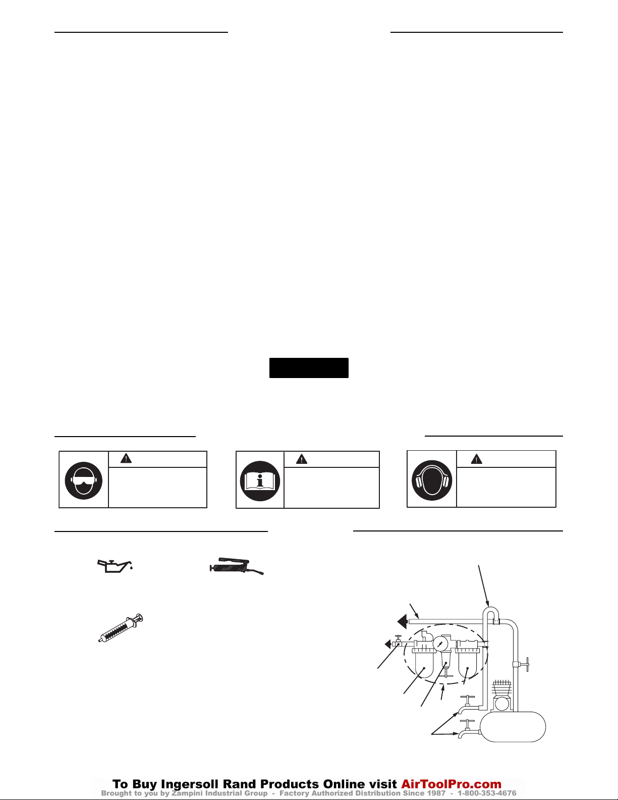
(Zeichn. TPD905-2)
Werkzeugeinsatz (Continued)
• Vermeiden Sie, sich den Schadstoffen auszusetzen und die
Schadstoffe einzuatmen, die bei Verwendung von Elektro- und
Druckluftwerkzeugen freigesetzt werden:
Bei der Nutzung von Maschinen zum Schleifen, Sägen,
Trennschleifen, Bohren und weiteren Tätigkeiten auf
dem Bausektor entstehen Stäube, die ihrerseits
Chemikalien enthalten, die bekanntermaßen Krebs,
Schädigungen der Nachkommen oder andere
Schädigungen des menschlichen
Reproduktionssystems verursachen. Zu Beispielen für
diese Chemikalien zählen:
- Blei, freigesetzt aus bleihaltigen Anstrichstoffen,
- Kristallines Silikat, abgegeben von Ziegeln und
Zement sowie weiteren Baustoffen und
- Arsen und Chrom, freigesetzt aus chemisch behandelten
Hölzern.
Die durch solche Aussetzungen bedingten Risiken für die
Gesundheit unterscheiden sich je nach der Häufigkeit, mit der
solche Tätigkeiten durchgeführt werden. Um die Aussetzung
zu diesen chemischen Stoffen herabzusetzen, sind folgende
Maßnahmen zu ergreifen: Alle Arbeiten sind in gut belüfteten
Bereichen durchzuführen und bei allen Arbeiten sind
zugelassene persönliche Schutzausrüstungen zu tragen. Hierzu
gehören beispielsweise Atemschutzmasken, die spezifisch auf
das Herausfiltern mikroskopisch kleiner Partikel ausgelegt sind.
• Elektro- und Druckluftwerkzeuge können während des Betriebs
vibrieren. Vibrationen, häufige gleichförmige Bewegungen oder
unbequeme Positionen können schädlich für Hände und Arme sein.
Bei Unbehagen, Kribbeln oder Schmerzen Werkzeuge nicht
weiterbenutzen. Vor dem erneuten Arbeiten mit dem Werkzeug
ärztlichen Rat einholen.
• Auf sichere Körperhaltung achten. Während der Benutzung des
Werkzeuges nicht zu weit nach vorne lehnen. Bei Anlauf und
Betrieb auf Rückschlag achten und auf plötzliche Änderungen der
Reaktionsdrehmomente und Gegenkräfte vorbereitet sein.
• Nach Freigabe des Drückers können Werkzeug und/oder
Zubehörteile noch kurzzeitig weiterlaufen.
• Zur Vermeidung unbeabsichtigten Anlaufens sicherstellen, daß das
Werkzeug ausgeschaltet ist, ehe die Druckluftversorgung hergestellt
wird. Werkzeug nicht am Drücker tragen und bei Verlust der
Druckluftversorgung den Drücker freigeben.
• Auf sicheren Sitz des Werkstücks achten. Wenn möglich,
Werkstück mit Zwingen festklemmen oder in einen Schraubstock
einspannen.
• Das Werkzeug nicht am Schlauch tragen oder ziehen.
• Werkzeug nicht in übermüdetem Zustand oder unter dem Einfluß
von Arzneimitteln, Drogen oderAlkohol einsetzen.
• Niemals ein beschädigtes oder nicht korrekt funktionierendes
Werkzeug oder Zubehörteil verwenden.
• Keine Modifikationen an Werkzeug, Sicherheitseinrichtungen oder
Zubehörteilen vornehmen.
• Dieses Produkt lediglich für die empfohlenen Verwendungszwecke
nutzen.
• Stets von Ingersoll-Rand empfohlenes Zubehör verwenden.
• Bei umsteuerbaren Modellen vor der Inbetriebnahme auf die
Stellung der Umsteuereinrichtung achten, damit bei Betätigung des
Drückers die Drehrichtung schon bekannt ist.
• Nur Schlagschrauber nur Steckschlüssel- Steckschlüssel und
Zubehör verwenden. Keine hand- Steckschlüssel (Chrom) oderZubehörteile verwenden.
• In regelmäßigen Zeitabständen die angetriebene Werkzeugseite
überprüfen um sicherzustellen, dass die Steckschlüsselhalterung
korrekt arbeitet und Steckschlüssel und Antriebsverlängerungen
keinen übermäßigen Verschleiß aufweisen, was bei drehendem
Werkzeug zu einem Lösen des Steckschlüssels führen könnte.
Die Verwendung von nicht Original-Ingersoll-Rand-Ersatzteilen kann Sicherheitsrisiken, verringerte Standzeit und erhöhten Wartungsbedarf nach
sich ziehen und alle Garantieleistungen ungültig machen.
Reparaturen sollen nur von geschultem Personal durchgeführt werden. Wenden Sie sich an Ihre nächste Ingersoll-Rand- Niederlassung oder den
autorisierten Fachhandel.
HINWEIS
ACHTUNG ACHTUNG
Beim Betreiben oder Warten
dieses Werkzeuges stets
Augenschutz tragen.
ACHTUNG
Dieses handbuch vor
inbetriebnahme des
werkzeuges unbedingt lesen.
Beim Betreiben dieses
Werkzeuges stets
Gehörschutz tragen.
NEBENROHRLEITUNG MIT
ZWEIFACHEM DURCHMESSER
DES LUFTEINLASSES
HAUPTROHRLEITUNG
MIT DREIFACHEM
ZUM
DRUCKLUFTWERKZEUG
DURCHMESSER DES
LUFTEINLASSES
ZUM
DRUCKLUFTSYSTEM
NOTO-US
ABSPERRVENTIL
ÖLER
REGLER
REGELMÄSSIG
ABLASSEN
R
O
F
FILTER
FRO
KOMPRESSOR
Page 10

10
EINSTELLUNGEN
Drehmomenteinstellung
Zum Einstellen des Drehmomentes bei diesen
zweilamelligen Impuls-Schraubern wird folgendermaflen
vorgegangen:
1. Den Stöpsel über der Einstellungs-Schraube entfernen.
2. Die Antriebswelle so weit drehen bis die DrehmomentEinstellschraube durch die Öffnung sichtbar ist. Es ist
Farbe im Kopf der Drehmoment-Einstellschraube.
3. Mit einem 1,5-mm-Imbusschlüssel die Einstellschraube
nach rechts drehen, um das Drehmoment zu steigern
und nach links drehen, um das Drehmoment zu
verringern.
4. Den Stöpsel wieder über der Einstellungs-Schraube
anbringen.
Alle endgültigen Einstellungen bei der Arbeit
vornehmen.
Gemäβ PNEUROP PN8NTC1.2
Nach ISO8662
Modell Schallpegel Schwingungs-
dB(A) Level
Druck Leistung m/s
2
40PSQ1 74,4 --- 0,8
45PS3 80,3 --- 0,5
45PSQ1 80,3 --- 0,5
55PS3 81,3 --- 0,7
55PSQ1 81,3 --- 0,7
70PS3 82,7 --- 0,8
90PS4 92,8 --- 1,6
HINWEIS
Page 11

IMPORTANTE INFORMAZIONE DI SICUREZZA ACCLUSA -
CONSERVARE QUESTE INSTRUZIONI
LEGGERE ATTENTAMENTE IL PRESENTE MANUALE PRIMA
DI USARE QUESTO PRODOTTO
QUESTE INFORMAZIONI SULLA SICUREZZA DEVONO ESSERE MESSE A
COMPLETA DISPONIBILITÀ DI COLORO CHE UTILIZZERANNO QUESTO PRODOTTO
LA MANCATA OSSERVANZA DELLE SEGUENTI AVVERTENZE PUÒ CAUSARE LESIONI FISICHE
Indirizzare tutte le comunicazioni al più vicino
concessionario od ufficio Ingersoll-Rand.
© Ingersoll-Rand Company 2002
Stampato in Giappone
• L’installazione, il funzionamento, l’ispezione e la
manutenzione di questo prodotto devono essere condotti in
conformità di tutte le normative e standard pertinenti (locali,
nazionali, regionali, ecc.).
• Usare sempre aria pulita e asciutta con pressione massima in
ingresso di 6,2 bar/620 kPa (90 psi). Se la pressione supera
questo valore si possono creare situazioni di pericolo, tra cui
velocità eccessiva, forza o coppia di uscita non corrette e
rotture.
• Assicurarsi che tutti i tubi ed i raccordi siano delle corrette
dimensioni e saldamente serrati. Consultare il disegno
TPD905-2 per una tipica disposizione dei tubi.]
• Accertarsi che la valvola d’ arresto di emergenza accessibile
sia stata installata nel tubo di alimentazione dell’aria e
rendere disponibile questa informazione.
• Non adoperare tubi e raccordi danneggiati, consunti o
deteriorati.
• Porre attenzione ai tubi flessibili che agiscono come fruste.
Chiudere l’aria compressa prima di avvicinarsi ad un tubo
flessibile in movimento.
• Disinserire sempre l’alimentazione aria e staccare il relativo
tubo dall’attrezzo, prima di installare, togliere o regolare
qualsiasi accessorio, oppure prima di eseguire qualsiasi
operazione di manutenzione dell’attrezzo.
• Non lubrificare gli attrezzi con liquidi infiammabili o volatili
come kerosene, gasolio o combustibile per aviogetti. Usare solo
i lubrificanti raccomandati.
• Tenere l’area di lavoro pulita, sgombra, ventilata ed
illuminata.
• Non togliere nessuna etichetta. Sostituire eventuali etichette
danneggiate.
04578084
Modulo P7528
Edizione 3
Giugno, 2002
I
ISTRUZIONI USEO E MANUTENZIONE PER CHIAVI IDRAULICHE AD
IMPULSI A DOPPIA PALETTA MODELLO 40PSQ1, 45PS3, 45PSQ1, 55PS3,
55PSQ1, 70PS3 E 90PS4 CON BLOCCO AUTOMATICO
Le chiavi idraulichead impulsi modelli 40PSQ1, 45PS3, 45PSQ1, 55PS3, 55PSQ1, 70PS3 e 90PS4
sono state progettate per operazioni di assemblaggio che richiedono alta velocità di scarico di
dispositivi di fissaggio con consistente mandata di coppia e ridotta reazione di coppia.
MESSA IN SERVIZIO DELL’ATTREZZO
• Indossare sempre degli occhiali protettivi quando si adopera
questo attrezzo o se ne esegue la manutenzione.
• Indossare sempre delle cuffie protettive quando si adopera
questo attrezzo.
• Indossare sempre attrezzatura protettiva adeguata allo
strumento e ai materiali in uso. Tra questi una mascherina
parapolvere o oggetti simili, occhiali di sicurezza, paraorecchi,
guanti, grembiule, scarpe di sicurezza, elmetto e altri
indumenti di protezione.
• Questo attrezzo non è stato progettato per essere impiegato in
ambienti a rischio di esplosione per fumi e polveri e nelle
vicinanze di materiali infiammabili.
• Questo utensile non è isolato contro le scosse elettriche.
• Informarsi sui pericoli nascosti nel proprio ambiente di lavoro.
Non toccare o danneggiare cavi, condotti, tubi o flessibili che
possano contenere cavi elettrici, gas esplosivi o liquidi
pericolosi.
• Tenere le persone ad una distanza di sicurezza dall’area di
lavoro ed accertarsi che esse utilizzino l’attrezzatura protettiva
adeguata.
• Tenere le mani, vestiti larghi, capelli lunghi e gioielleria fuori
dalla portata del lato in funzione dell’utensile.
COME USARE L’ATTREZZO
AVVISO
AVVERTENZA
Page 12
12
IDENTIFICAZIONE DEI SIMBOLI DE AVVERTENZA
LUBRIFICAZIONE
Ingersoll-Rand No. 50 Ingersoll-Rand No. 68
Ingersoll-Rand Fluido
Parte Nr. EQ106S-400-1
Dopo ogni 20.000 cicli, oppure come suggerito
dall’esperienza acquisita, scarire e riempire di nuovo il
complessivo dell’attacco dell’unità di attacco ad impulsi
secondo le istruzioni riportate nel manuale utilizzando il kit
di sostituzione del fluido (Parte Nr. EQ106S-K400).
Lubrificare l’attacco esagonale e l’albero di uscita prima
dell’assemblaggio.
(il desegno TPD905-2)
Come Usare l’Attrezzo (Continued)
• Prevenire l’esposizione e la respirazione di polvere e particelle
pericolose dovute all’uso si stumenti elettrici:
La polvere causata da smerigliatura, segatura,
macinatura, trapanatura e altre attività relative alla
costruzione contiene sostanze chimiche note come cause
di cancro, di menomazioni alla nascita o di altri danni
legati alla riproduzione. Tali sostanze chimiche sono, ad
esempio:
- vernici a base di piombo,
- silice cristallina derivante da mattoni e cemento e altri
prodotti per muratura,
- arsenico e cromo derivanti da legname trattato
chimicamente.
I rischi causati dalle esposizioni variano in base alla
frequenza con cui viene eseguito questo tipo di lavori. Per
ridurre l’esposizione a tali sostanze chimiche: lavorare in
una zona ben ventilata, con attrezzature di sicurezza
approvate come le maschere per protezione dalla polvere
progettate specificamente per eliminare con il filtro le
particelle microscopiche.
• Gli attrezzi elettrici sono soggetti a vibrazioni durante l’uso.
Le vibrazioni, i movimenti ripetitivi o le posizioni scomode
possono risultare dannosi per mani e braccia. Interrompere
l’uso dell’attrezzo se si avvertono sintomi di disagio fisico,
formicolio o dolore. Interpellare un medico prima di
riprendere il lavoro.
• Mantenere con il corpo una posizione salda e ben bilanciata.
• Non sbilanciarsi durante l’uso di questo utensile. Fare
attenzione e cercare di anticipare improvvise variazioni di
movimento, coppie di reazione, o forze inaspettate durante
l’avviamento e l’uso di qualsiasi utensile.
• Lo strumento e/o gli accessori potrebbero continuare a
ruotare per un breve tempo dopo il disinserimento della
valvola a farfalla.
• Per evitare avvii accidentali – accertarsi che lo strumento sia
in posizione “off” prima di applicare la pressione dell’aria,
evitare di toccare la valvola a farfalla durante lo spostamento,
rilasciare la valvola a farfalla in caso di perdite d’aria.
• Accertarsi che i pezzi di lavorazione siano sicuri Consigliamo
di usare dei morsetti o una morsa per bloccare, il pezzo in
lavorazione.
• Non trasportare o trascinare l’attrezzo tenendolo per il tubo.
• Evitare l’uso degli attrezzi elettrici quando si è stanchi, sotto
l’effetto di medicinali, droghe o alcol.
• Non usare mai attrezzi o accessori danneggiati o
malfunzionanti.
• Non modificare in alcun modo lo strumento, i dispostivi di
sicurezza o gli accessori.
• Non usare questo prodotto per scopi diversi da quelli
consigliati.
• Utilizzare gli accessori consigliati dalla Ingersoll-Rand.
• Nei modelli reversibili, prendere nota della posizione del
meccanismo di inversione prima di azionare l’attrezzo in
modo da conoscere la direzione di rotazione quando si aziona
la valvola di azionamento.
• Utilizzare esclusivamente bussole per chiavi ad impulso e
relativi accessori. Non si devono utilizzare bussole (cromate)
ed accessori di uso manuale.
• Controllare periodicamente gli accoppiamenti dello strumento
per accertarsi che i fermi dei giunti funzionino correttamente
e che i giunti e gli accoppiamenti non siano usurati in modo
tale che il giunto possa staccarsi durante la rotazione.
L’uso di ricambi non originali Ingersoll-Rand potrebbe causare condizioni di pericolosità, compromettere le prestazioni
dell’attrezzo ed aumentare la necessità di manutenzione, inoltre potrebbe invalidare tutte le garanzie.
Le riparazioni devono essere effettuate soltanto da personale autorizzato e qualificato. Rivolgersi al più vicino centro di assistenza
tecnica Ingersoll-Rand.
AVVISO
A
AVVERTENZA
Indossare sempre degli occhiali
protettivi quando si adopera
questo attrezzo o se ne esegue
la manutenzione.
AVVERTENZA
Leggere il presente manuale
prima di usare l’attrezzo.
VVERTENZA
Indossare sempre delle
cuffie protettive quando si
adopera questo attrezzo.
DIRAMAZIONE, 2 VOLTE
LA DIMENSIONE
DELL'ENTRATA ARIA
DELL'UTENSILE
TUBAZIONE PRINCIPALE,
ALL'UTENSILE
PNEUMATICO
VALVOLA DI
INTERCETTAZIONE
DI EMERGENZA
3 VOLTELA DIMENSIONE
DELL'ENTRATA ARIA
DELL'UTENSILE
ALL'IMPIANTO
PNEUMATICO
LUBRIFICATORE
REGOLATORE
SVUOTARE
REGOLARMENTE
R
L
FRL
F
FILTRO
COMPRESSORE
Page 13

13
REGOLAZIONI
Regolazioni della Coppia
Per regolare la coppia di queste chiavi idrauliche ad impulsi
a doppia lama, procedere nel modo seguente:
1. Togliere il tappo del foro di regolazione.
2. Ruotare il mandrino fino a che la vite di regolazione
della coppia sia visibile attraverso l’apertura del foro di
regolazione. La testa della vite di regolazione della
coppia è verniciata.
3. Usando una chiave esagonale da 1,5 mm, ruotare la
vite di regolazione in senso orario per incrementare
l’erogazione di coppia, oppure in senso antiorario per
diminuirla. Non girare il tappo dell’olio.
4. Sostituire il tappo del foro di regolazione.
Effetuare tutte le regolazioni finali durante il
lavoro.
Collaudato secondo i criteri PNEUROP PN8NTC1.2
Collaudato secondo i criteri ISO8662
Modello Livello suono Livello di
dB(A) vibrazione
Pressione Potenza m/s
2
40PSQ1 74,4 --- 0,8
45PS3 80,3 --- 0,5
45PSQ1 80,3 --- 0,5
55PS3 81,3 --- 0,7
55PSQ1 81,3 --- 0,7
70PS3 82,7 --- 0,8
90PS4 92,8 --- 1,6
AVVISO
Page 14
SE ADJUNTA INFORMACIÓN IMPORTANTE DE SEGURIDAD -
GUARDE ESTAS INSTRUCCIONES
LEA ESTE MANUAL Y ASEGÚRESE DE COMPRENDERLO
BIEN ANTES DE UTILIZAR ESTE APARATO
ES SU RESPONSABILIDAD PONER ESTA INFORMACIÓN DE SEGURIDAD
A DISPOSICIÓN DE QUIENES VAYAN A UTILIZAR EL APARATO
EL HACER CASO OMISO DE LOS AVISOS SIGUIENTES PODRÍA OCASIONAR LESIONES
Toda comunicación se deberá dirigir a la oficina o al
distribuidor Ingersoll-Rand más próximo.
© Ingersoll-Rand Company 2002
Impreso en Japón
• Instale, utilice, inspeccione y mantenga siempre este aparato de
acuerdo con todas las normas locales y nacionales que sean de
aplicación.
• Use siempre aire limpio y seco a una presión máxima de 90 psig
(6,2 bar/620 kPa) en la admisión. Una presión superior puede
redundar en situaciones peligrosas, entre ellas una velocidad
excesiva, rotura, o un par o una fuerza de salida incorrectos.
• Asegúrese de que todas las mangueras y accesorios sean del
tamaño correcto y estén bien apretados. Vea Esq. TPD905-2
para un típico arreglo de tuberías.
• Cerciórese de que se haya instalado una válvula de corte de
emergencia en la línea de suministro de aire y notifique a los
demás de su ubicación.
• No utilizar mangueras de aire y accesorios dañados, desgastados
ni deteriorados.
• Manténgase apartado de toda manguera de aire que esté dando
latigazos. Apague el compresor de aire antes de acercarse a una
manguera de aire que esté dando latigazos.
• Corte siempre el suministro de aire y desconecte la manguera de
suministro de aire antes de instalar, desmontar o ajustar
cualquier accesorio de esta herramienta, o antes de realizar
cualquier operación de mantenimiento de la misma.
• No lubrique las herramientas con líquidos inflamables o volátiles
tales como queroseno, gasoil o combustible para motores a
reacción. Use únicamente los lubricantes recomendados.
• Mantenga la zona de trabajo limpis, despejada, ventilada e
iluminada.
• No saque ninguna etiqueta. Sustituya toda etiqueta dañada.
04578084
Impreso P7528
Edición 3
Junio, 2002
E
MANUAL DE INSTRUCCIONES DE MANEJO Y MANTENIMIENTO PARA
LLAVES DE IMPULSOS DE DOBLE PALETA DE PARADA AUTOMÁTICA
MODELOS 40PSQ1, 45PS3, 45PSQ1, 55PS3, 55PSQ1, 70PS3 Y 90PS4
Las Llaves de Impulso Modelos 40PSQ1, 45PS3, 45PSQ1, 55PS3, 55PSQ1, 70PS3 y 90PS4 están
diseñadas para operaciones de ensamblaje que requieren alta velocidad de fijación con par
consistente y reducida reacción de par.
PARA PONER LA HERRAMIENTA EN SERVICIO
• Use siempre protección ocular cuando maneje, o realice
operaciones de mantenimiento en esta herramienta.
• Use siempre protección para los oídos cuando maneje esta
herramienta.
• Utilice siempre el equipo de protección individual que
corresponda a la herramienta en uso y al material con el que se
trabaja. Ello puede incluir una mascarilla contra el polvo u otro
aparato de respiración, gafas de seguridad, tapones de oído,
guantes, delantal, zapatos de seguridad, casco y otros artículos.
•
Esta herramienta no está diseñada para su utilización en
ambientes explosivos, incluidos los que son provocados por la
presencia de vapores y polvo, o cerca de materiales inflamables.
• Esta herramienta no está aislada contra descargas eléctricas.
•
Tenga en cuenta los peligros enterrados, ocultos o de otro tipo en
el entorno de trabajo. Tenga cuidado de no hacer contacto con, ni
dañar, cables, conductos, tuberías ni mangueras que puedan
contener hilos eléctricos, gases explosivos o líquidos nocivos.
• Mantenga a los demás a una distancia segura de la zona de
trabajo, o asegúrese de que utilicen el correspondiente equipo de
protección individual.
• Mantenga las manos, la ropa suelta, el cabello largo y las alhajas
apartados del extremo de trabajo de la herramienta.
USO DE LA HERRAMIENTA
NOTA
AVISO
Page 15
15
IDENTIFICACIÓN DE SÍMBOLOS DE AVISO
LUBRICACIÓN
Ingersoll-Rand N°. 50 Ingersoll-Rand N°. 68
Fluido Ingersoll-Rand
Pieza N°. EQ106S-400-1
Después de cada 20.000 ciclos, o como indique la
experiencia, drene y vuelva a llenar el Conjunto de
Accionamiento de Unidad de Impulso tal y como se indica
en este manual, usando el equipo de cambio de fluido
(Pieza N°. EQ106S-K400). Lubrique el eje de salida y
accionamiento hexagonal antes del montaje.
(Esq. TPD905-2)
Uso de la Herramienta (Continued)
• Evite respirar el polvo y partículas nocivos que se producen al
utilizar la herramienta, así como exponerse a ellos:
Ciertos tipos de polvo que se producen al lijar, serruchar,
rectificar o taladrar y durante otras actividades de la
construcción contienen sustancias químicas que son
conocidos como causantes de cáncer, defectos de nacimiento
y otros daños reproductivos. Algunos ejemplos de estas
sustancias químicas:
- el plomo de las pinturas con base de plomo,
- la sílice cristalina de ladrillos y hormigón y otros
productos asociados con la albañilería, y
- el arsénico y el cromo que produce la madera sometida a
tratamientos químicos.
El riesgo a la persona que presenta una exposición de ste
tipo varia en función de la frecuencia con que se realiza
esta clase de trabajo. Para reducir la exposición a estas
sustancias químicas: trabaje en una zona bien ventilada y
utilice equipo de protección homologado, por ejemplo una
mascarilla especialmente diseñada para filtrar partículas
microscópicas.
• Las herramientas eléctricas pueden vibrar durante el uso. La
vibración, los movimientos repetitivos o las posiciones incómodas
pueden dañarle los brazos y manos. En caso de incomodidad,
sensación de hormigueo o dolor, deje de usar la herramienta.
Consulte con el médico antes de volver a utilizarla.
• Mantenga una postura del cuerpo equilibrada y firme. No estire
demasiado los brazos al manejar la herramienta. Anticipe y esté
atento a los cambios repentinos en el movimiento, pares de
reacción u otras fuerzas durante la puesta en marcha y
utilización.
• El movimiento de la herramienta y/o los accesorios puede
prolongarse brevemente después de soltarse el mando.
• Para evitar el arranque imprevisto de la herramienta, verifique
que esté en la posición de desconexión “off” antes de aplicarle aire
a presión, evite tocar el mando al transportarla y suelte el mando
mientras se descarga el aire.
• Asegúrese de que las piezas a trabajar estén bien sujetas. Siempre
que sea posible, utilice mordazas o un tornillo de banco para
sostener la pieza.
• No lleve ni arrastre la herramienta sujetándola por la manguera.
• No utilice herramientas eléctricas cuando esté cansado o bajo la
influencia de medicamentos, drogas o alcohol.
• No utilice nunca una herramienta o un accesorio dañado o que no
funcione correctamente.
• No modifique la herramienta, los dispositivos de seguridad ni los
accesorios.
• No utilice esta aparato para otros fines que no sean los
recomendados.
• Utilice únicamente los accesorios recomendados por IngersollRand.
• Para motores reversibles, tome nota de la posición del mecanismo
inversor antes de poner en marcha la herramienta para tener en
cuenta el sentido de rotación al accionar el mando.
• Utilice únicamente bocas y accesorios para llave de impacto con
esta herramienta. No utilice bocas ni accesorios manuales
(cromados).
• Revise periódicamente el extremo de accionamiento de la
herramienta para asegurarse de que el retenedor de bocas
funcione correctamente y que las bocas y los extremos de
accionamiento no presenten un desgaste excesivo que pueda
permitir que la boca se salga al girar.
NOTA
El uso de piezas de recambio que no sean las auténticas piezas Ingersoll-Rand podría poner en peligro la seguridad, reducir el
rendimiento de la herramienta y aumentar los cuidados de mantenimiento necesarios, así como invalidar toda garantía.
Las reparaciones sólo serán realizadas por personal cualificado y autorizado. Consulte con el centro de servicio Ingersoll-Rand
autorizado más próximo.
ADVERTENCIA
Use siempre protección ocular
cuando utilice esta herramienta
o realice operaciones de
mantenimiento en la misma.
ADVERTENCIA
Lea este manual antes de
usar la herramienta.
ADVERTENCIA
Use siempre protección
para los oÌdos cuando
utilice esta herramienta.
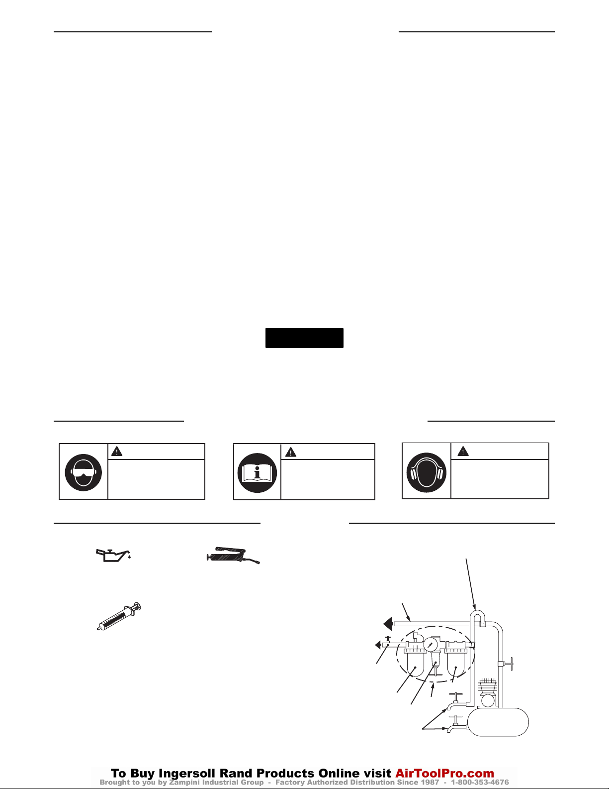
TUBERÍA DE RAMAL 2 VECES
EL TAMAÑO DE ENTRADA
DE HERRAMIENTA NEUMÁTICA
F
COMPRESOR
TUBERÍAS PRINCIPALES
3 VECES EL TAMAÑO
DE ENTRADA DE
HERRAMIENTA NEUMÁTICA
AL SISTEMA
NEUMÁTICO
A LA HERRAMIENTA
NEUMÁTICA
VÁLVULA DE
CORTE DE
EMERGENCIA
LUBRICADOR
REGULADOR
PURGAR
PERIÓDICAMENTE
R
L
FILTRO
FRL
Page 16

16
AJUSTES
Ajuste de Par
Para ajustar el par de estas Llaves de Impulso de Doble
Paleta, proceda como sigue:
1. Saque el Tapón de Orificio de Ajuste.
2. Gire el Eje de Accionamiento hasta que el Tornillo de
Ajuste de Par sea visible a través de dicho orificio. El
tornillo de ajuste de par tiene pintura de color
en el hueco de la cabeza.
3. Utilice una llave hexagonal de 1,5 mm para girar el
tornillo de ajuste hacia la derecha para aumentar la
salida de par y hacia la izquierda para reducirlo. No
gire el tapón del aceite.
4. Vuelva a poner en su sitio el Tapón de Orificio de
Ajuste.
Haga todos los ajustes finales trabajando.
Probado en conformidad con PNEUROP PN8NTC1.2
Probado ISO8662
Modelo Nivel de sonido Nivel de
dB(A) Vibraciones
Presión Potencia m/s
2
40PSQ1 74,4 --- 0,8
45PS3 80,3 --- 0,5
45PSQ1 80,3 --- 0,5
55PS3 81,3 --- 0,7
55PSQ1 81,3 --- 0,7
70PS3 82,7 --- 0,8
90PS4 92,8 --- 1,6
NOTA
Page 17
BELANGRIJKE VEILIGHEIDSINFORMATIE IS INGESLOTEN -
DEZE INSTRUCTIES GOED BEWAREN
ZORG ERVOOR DAT U DEZE HANDLEIDING DOORGELEZEN
EN BEGREPEN HEBT ALVORENS HET PRODUCT TE GEBRUIKEN
U BENT ER ZELF VOOR VERANTWOORDELIJK OM DEZE INFORMATIE TER
BESCHIKKING TE STELLEN VAN ANDERE PERSONEN DIE GEBRUIK MAKEN VAN DIT PRODUCT
EEN NALATEN DE HIERNAVOLGENDE WAARSCHUWINGEN OP TE VOLGEN KAN
LICHAMELIJK LETSEL TOT GEVOLG HEBBEN
Richt al uw communicatie tot het dichtstbijzijnde
Ingersoll-Rand Kantoor of Wederverkoper.
© Ingersoll-Rand Company 2002
Gedrukt in Japan
• Dit product moet altijd geïnstalleerd, geïnspecteerd en
onderhouden worden in overeenstemming met alle geldende
normen en richtlijnen (plaatselijk, landelijk, internationaal, enz.).
• Gebruik altijd schone, droge lucht op 90 psig (6,2 bar/620 kPa).
maximum luchtdruk bij de inlaat. Een hogere druk kan tot
gevaarlijke situaties leiden, inclusief een te hoge snelheid,
stukspringen of incorrect geleverde koppel of kracht.
• Zorg ervoor dat alle slangen en fittingen de juiste afmetingen
hebben en goed zijn vastgemaakt. Zie tekening TPD905-2 voor
een typisch leidingnet.
• Er moet een bereikbaar noodafsluitventiel in de leiding van de
luchttoevoer zijn aangebracht en andere personen moeten worden
ingelicht over de locatie hiervan.
• Geen beschadigde, gerafelde of versleten luchtslangen of fittingen
gebruiken.
• Blijf uit de buurt van zwiepende luchtslangen. Schakel de
perslucht uit alvorens een zwiepende luchtslang te benaderen.
• Men dient te allen tijde de luchtinlaat af te sluiten en de
luchttoevoerslang te ontkoppelen voordat enig deel aan dit
gereedschap wordt aangebracht, verwijderd of afgesteld, of
voordat enig onderhoud aan dit gereedschap mag worden
uitgevoerd.
• Gereedschappen mogen niet gesmeerd worden met ontvlambare
of vluchtige vloeistoffen zoals petroleum, diesel of
vliegtuigbrandstof. Gebruik uitsluitend aanbevolen
smeermiddelen.
• De werkomgeving schoon, ordelijk, goed geventileerd en verlicht
houden.
• Geen typeplaatjes verwijderen. Beschadigde typeplaatjes moeten
worden vervangen.
04578084
Form P7528
Versie 3
Juni, 2002
NL
BEDIENINGS- EN ONDERHOUDSHANDBOEK VOOR TYPEN
40PSQ1, 45PS3, 45PSQ1, 55PS3, 55PSQ1, 70PS3 EN 90PS4
DUBBELBLADIGE IMPULSMACHINES MET AFSLAG
De Typen 40PSQ1, 45PS3, 45PSQ1, 55PS3, 55PSQ1, 70PS3 en 90PS4 Dubbelbladige Aanzetsleutels zijn
bedoeld voor assemblagewerkzaamheden die een met hoge snelheid aandraaien van bevestigingsmiddelen
nodig hebben met een constant aanzetmoment en een verminderde koppelreactie.
INGEBRUIKNEMING VAN HET GEREEDSCHAP
• U moet te allen tijde oogbeschermers dragen wanneer u dit
gereedschap bedient of er onderhoudswerkzaamheden aan
uitvoert.
• Altijd oorbeschermers dragen wanneer dit gereedschap wordt
bediend.
• Gebruik altijd persoonlijke beschermingsmiddelen die geschikt
zijn voor het gebruikte gereedschap. Dat kan onder andere zijn:
stofmasker of ander ademhalingsapparaat, veiligheidsbril,
oordoppen, handschoenen, schort, veiligheidsschoenen, helm en
ander materieel.
• Dit gereedschap is niet ontworpen voor gebruik in een explosieve
omgeving, inclusief waar dit veroorzaakt is door dampen en stof,
noch voor gebruik in de buurt van brandbare materialen.
• Dit gereedschap is niet geïsoleerd tegen elektrische schokken.
• Houd rekening met ingegraven, verborgen voorwerpen of andere
gevaren in uw werkomgeving. Buizen, leidingen of slangen die
elektrische bedrading, explosieve gassen of gevaarlijke vloeistoffen
kunnen bevatten mogen niet aangeraakt of beschadigd worden.
• Houd andere personen op veilige afstand van uw werkplek of zorg
ervoor dat zij persoonlijke beschermingsmiddelen gebruiken.
• De handen, losse kleding, lang haar en sierraden uit de buurt van
het bewegende einde van het gereedschap houden.
GEBRUIK VAN HET GEREEDSCHAP
LET WEL
WAARSCHUWING
Page 18
18
IDENTIFICATIE WAARSCHUWINGSSYMBOOL
DE SMERING
Ingersoll-Rand Nr. 50 Ingersoll-Rand Nr. 68
Ingersoll-Rand Vloeistof
Onderdeel Nr.
EQ106S-400-1
Na elke 20.000 cycli, of zoals de praktijk u heeft geleerd,
de Aandrijving voor de Aanzeteenheid aftappen en, zoals in
dit handboek gezegd, opvullen met de Vloeistof uit de
Vervangingskit (Onderdeel Nr. EQ106S-K400).
Voor de assemblage eerst de zeskante inbusaandrijving en
de uitgangsas smeren.
(Tekening TPD905-2)
Gebruik van het Gereedschap (Continued)
• Voorkom blootstelling aan en inademen van schadelijke stoffen
een deeltjes die vrijkomen bij gebruik van elektrisch gereedschap:
De stof die veroorzaakt wordt door schuren, zagen, afslijpen
en boren met elektrisch gereedschap, alsmede andere
constructiewerkzaamheden, bevat chemicaliën die bekend
staan als kankerverwekkend en die geboorteafwijkingen of
andere voor de voortplanting nadelige gevolgen kunnen
hebben. Enkele van deze chemicaliën zijn:
- lood uit loodhoudende verf ;
- kristallijnsilica in baksteen, cement en andere
metselwerkproducten;
- arsenicum en chroom in met chemicaliën behandeld
timmerhout.
De risicofactor op grond van deze blootstellingen varieert,
afhankelijk van de regelmaat waarmee u deze
werkzaamheden verricht. De blootstelling aan deze
chemicaliën kan als volgt worden gereduceerd: werk in een
goed geventileerde ruimte en met goedgekeurde
beschermingsmiddelen, zoals stofmaskers die specifiek
ontworpen zijn voor het uitfilteren van microscopische
deeltjes.
• Elektrisch gereedschap kan trillen tijdens het gebruik. Trilling,
herhaaldelijke bewegingen of oncomfortabele posities kunnen
schadelijk zijn voor uw handen en armen. Stop met het gebruik
van gereedschap wanneer u ongemak of een tintelend gevoel of
pijn ervaart. Vraag medisch advies alvorens het werk te
hervatten.
• Zorg voor gebalanceerde en stevige lichaamshouding. Niet te ver
uitreiken tijdens gebruik van dit gereedschap. Anticipeer en let op
veranderingen in beweging, reactiekoppels of krachten tijdens
starten en gebruik.
• Het gereedschap en/of de bijbehorende hulpstukken kunnen korte
tijd blijven doordraaien nadat de regelhendel wordt losgelaten.
• Om ongewild starten te voorkomen moet het gereedschap in de
stand “uit” zijn gezet, voordat de luchtdruk wordt ingeschakeld.
Bij het dragen de regelhendel niet aanraken en de regelhendel met
luchtverlies loslaten lloslaten.
• De werkstukken moeten goed vastgezet zijn. Maak zoveel
mogelijk gebruik van klemmen of bankschroeven om het
werkstuk vast te zetten.
• Het werktuig niet aan de slang dragen of slepen.
• Gebruik geen elektrisch gereedschap bij vermoeidheid of onder de
invloed van medicijnen, drugs of alcohol.
• Gebruik nooit een beschadigd of defect gereedschap of accessoire.
• Het gereedschap, de veiligheidsinrichtingen of bijbehorende
hulpstukken mogen niet gemodificeerd worden.
• Dit product uitsluitend gebruiken voor de aanbevolen doeleinden.
• Uitsluitend de door Ingersoll-Rand aanbevolen bijbehorende
hulpstukken gebruiken.
• Bij omkeerbare typen dient u voordat het gereedschap in gebruik
wordt genomen eerst op de stand van de omkeerhendel te letten,
zodat u de draairichting kent wanneer de regelaar wordt
gebruikt.
• Gebruik alleen slagmoersleuteldoppen en bijbehorende
hulpstukken op deze slagmoersleutel. Geen handmoersleutels
(chroom) of bijbehorende hulpstukken gebruiken.
• Controleer regelmatig het aandrijfeinde van het gereedschap om
er zeker van te zijn dat de borgpen voor de dopsleutel goed
functioneert en dat de moerdoppen en aandrijfeinden niet te ver
versleten zijn, waardoor de moerdop tijdens het draaien van de
moer af zou kunnen komen.
LET WEL
Het gebruiken van andere dan originele Ingersoll-Rand onderdelen kan gevaar opleveren voor de veiligheid, en een vermindering met zich
brengen van het prestatievermogen van het gereedschap en een toeneming van het onderhoud ervan; het kan een vervallen van alle
garantie-bepalingen tot gevolg hebben.
Reparaties mogen uitsluitend worden uitgevoerd door hiertoe gemachtigd en geschoold personeel. Raadpleeg uw dichtstbezijnde erkende
Ingersoll-Rand Servicenter.
WAARSCHUWING WAARSCHUWING
U moet te allen tijde
oogbeschermers dragen
wanneeru dit gereedschap
bedient of er
onderhoudswerkzaamheden
aan uitvoert.
WAARSCHUWING
Eerst dit handboek lezen,
dan het gereedschap
bedienen.
Altijd oorbeschermers
dragen wanneer dit
gereedschap wordt
bediend.
AFTAKKENDE LEIDING
2 MAAL AFMETING VAN
INLAAT VOOR DRUKLUCHTGEREEDSCHAP
NAAR
LUCHTSYSTEEM
HOOFDLEIDINGEN
3 MAAL AFMETINGVAN
INLAATVOOR DRUKLUCHTGEREEDSCHAP
NAAR
DRUKLUCHTGEREEDSCHAP
NOODAFSLUITVENTIEL
SMEERINRICHTING
REGELAAR
REGELMATIG
AFTAPPEN
R
S
F
FILTER
FRS
COMPRESSOR
Page 19

19
AFSTELLEN
Afstelling van het Koppel
Het afstellen van het koppel op deze Dubbelbladige
Aanzetsleutels gebeurt als volgt:
1. Verwijder de Plug voor het Stelgat.
2. Draai de Aandrijfas rond tot de Stelschroef voor het
Koppel in de opening zichtbaar wordt. In de kop van
de Koppelinstelsleutel is gekleurde verf aangebracht.
3. Met een 1.5 mm zeskante sleutel de Stelschroef met de
klok mee draaien om het koppelvermogen te vergroten
en tegen de klok in draaien om het koppelvermogen te
laten afnemen.
De Olieplug niet ronddraaien.
4. Breng de Plug voor het Stelgat weer aan.
Maak alle laatste afstellingen op het werk zelf.
Getest volgens PNEUROP PN8NTC1.2
Getest volgens ISO8662
Type Geluidsniveau Trillings-
dB(A) niveau
Druk Vermogen m/s
2
40PSQ1 74,4 --- 0,8
45PS3 80,3 --- 0,5
45PSQ1 80,3 --- 0,5
55PS3 81,3 --- 0,7
55PSQ1 81,3 --- 0,7
70PS3 82,7 --- 0,8
90PS4 92,8 --- 1,6
LET WEL
Page 20
INDEHOLDER VIGTIG SIKKERHEDSINFORMATION -
DENNE VEJLEDNING BØR GEMMES
LÆS OG FORSTÅ DENNE VEJLEDNING, FØR PRODUKTET TAGES I BRUG
DU HAR ANSVAR FOR AT GØRE DISSE SIKKERHEDSOPLYSNINGER
TILGÆNGELIGE FOR ANDRE, DER SKAL BETJENE DETTE PRODUKT
MANGLENDE IAGTTAGELSE AF DISSE ADVARSLER KAN RESULTERE I PERSONSKADE
Al korrespondance bedes stilet til Ingersoll-Rands
nærmeste kontor eller distributør.
© Ingersoll-Rand Company 2002
Trykt i Japan
• Dette produkt skal altid installeres, betjenes, kontrolleres og
vedligeholdes i overensstemmelse med de gældende lokale og
nationale regler.
• Der skal altid bruges ren, tør luft ved et maksimalt lufttryk på
6,2 bar. Højere tryk kan forårsage farlige situationer,
herunder for høj hastighed, sprængning eller forkert
arbejdsmoment.
• Det skal sikres, at alle slanger og alt tilbehør er af den
korrekte størrelse og er sikkert monteret. Der henvises til
tegning TPD905-2, som viser en typisk rørføring.
• Sørg for, at der er installeret en tilgængelig nødstopventil i
lufttilførselsledningen, og gør andre opmærksom på dens
placering.
• Der må ikke bruges beskadigede, flossede eller nedslidte
luftslanger og tilbehør.
• Hold afstand til piskende luftslanger. Trykluftforsyningen
skal altid afbrydes, før man nærmer sig en piskende
luftslange.
• Der skal altid lukkes for lufttilførslen, og lufttilførselsslangen
skal afmonteres før installation, afmontering eller justering af
tilbehør til dette værktøj, eller før der udføres
vedligeholdelsesarbejde på værktøjet.
• Værktøjer må ikke smøres med brændbare eller flygtige
væsker så som petroleum, dieselolie eller flybrændstof. Der
må kun anvendes anbefalede smøremidler.
• Hold arbejdsområdet rent, ryddeligt, udluftet og oplyst.
• Mærkater må ikke fjernes. Eventuelt beskadigede mærkater
skal udskiftes.
04578084
Formular P7528
3. Udgave
Juni, 2002
DK
BETJENINGS- OG VEDLIGEHOLDELSESMANUAL TIL HYDRAULISK
DÆMPEDE DOBBELTLAMEL-SPÆNDENØGLER,
MODEL 40PSQ1, 45PS3, 45PSQ1, 55PS3, 55PSQ1, 70PS3 OG 90PS4
Hydraulisk dæmpede spændenøgler model 40PSQ1, 45PS3, 45PSQ1, 55PS3, 55PSQ1, 70PS3 og
90PS4 er designet til montagearbejde, der kræver hurtig tilspænding af møtrikker med ensartet
moment og reduceret reaktionsmoment.
IBRUGTAGNING AF VÆRKTØJET
• Der skal altid bruges beskyttelsesbriller under betjening eller
vedligeholdelse af værktøjet.
• Der skal altid bruges høreværn under betjening af dette
værktøj.
• Anvend altid personligt beskyttelsesudstyr, som er passende for
det anvendte værktøj og bearbejdede materiale. Dette kan
omfatte en støvmaske eller andet åndedrætsværn,
beskyttelsesbriller, ørepropper, handsker, forklæde,
sikkerhedssko, sikkerhedshjelm og andet udstyr.
• Dette værktøj er ikke konstrueret til arbejde i eksplosive
miljøer, herunder miljøer med dampe eller støv, eller i
nærheden af brændbare materialer.
• Dette værktøj er ikke isoleret mod elektriske stød.
• Vær opmærksom på nedgravede, skjulte og andre farer i
arbejdsmiljøet. Pas på ikke at berøre eller beskadige ledninger,
rørledninger, rør og slanger, der kan indeholde elektriske
ledere, eksplosive gasser eller farlige væsker.
• Hold andre på god afstand af arbejdsområdet, eller sørg for, at
de anvender passende beskyttelsesudstyr.
• Hold hænder, løse beklædningsdele, langt hår og smykker væk
fra værktøjets arbejdsende.
ANVENDELSE AF VÆRKTØJET
BEMÆRK
ADVARSEL!
Page 21
21
ADVARSELSSYMBOLER
SMØRING
Ingersoll-Rand nr. 50 Ingersoll-Rand nr. 68
Ingersoll-Rand væske,
bestillingsnr.
EQ106S-400-1
For hver 20 cyklusser, eller som erfaringerne tilsiger det,
skal impulsmekanismens drivenhed drænes og genopfyldes
med væske fra væskeudskiftningssættet (bestillingsnr.
EQ106S-K400) som beskrevet i denne vejledning.
Hexagonaldrevet og udgangsakslen smøres, før værktøjet
samles.
(Tegning TPD905-2)
Anvendelse af Værktøjet (Continued)
• Forebyggelse af risici ved udsættelse for og indånding af
helbredsskadeligt støv og partikler fra brug af trykluft- og
elværktøj:
Visse typer støv fra pudsning, savning, slibning, boring
og andet byggearbejde med trykluftsværktøj eller
elværktøj indeholder kemikalier, som vides at forårsage
kræft, fødselsdefekter og andre skader i forbindelse med
menneskers forplantningsevne. Eksempler på disse
kemikalier omfatter:
- bly fra blyholdig maling,
- krystallinsk siliciumdioxid fra mursten, cement og
andre murværksmaterialer, samt
- arsenik og chrom fra kemisk behandlet tømmer.
Risikoen, du udsættes for fra disse kemikalier, varierer,
afhængig af hvor ofte du udfører denne type arbejde. Du
kan reducere risikoen ved udsættelse for disse kemikalier
som følger: arbejd i områder med god udluftning, og
arbejd med godkendt sikkerhedsudstyr, herunder
støvmasker, der er specielt fremstillet til at bortfiltrere
mikroskopiske partikler.
• El- og trykluftværktøjer kan vibrere under brug. Vibration,
hyppigt gentagne bevægelser og ubekvemme stillinger kan
være skadelige for operatørens hænder og arme. Brug af
værktøjet bør ophøre, hvis man føler nogen form for gener, en
snurrende fornemmelse i kroppen eller smerter. Der skal søges
lægehjælp, før brug af værktøjet genoptages.
• Der skal hele tiden holdes en kropsstilling med god balance og
godt fodgreb. Som operatør skal man undgå at strække sig for
langt under brug af dette værktøj. Under opstart og betjening
skal man forsøge at forudse og være særdeles opmærksom
over for pludselige bevægelsesændringer, reaktionsmomenter
og maskinkræfter.
• Værktøjets og/eller tilbehørets bevægelse kan fortsætte et kort
øjeblik efter, at startknappen slippes.
• Undgå utilsigtet start af værktøjet ved at sikre, at det er
indstillet til “off”, før lufttrykket tilføres, ved at undgå at
trykke på startknappen og ved at slippe startknappen, mens
luften er ved at blive lukket ud.
• Sørg for, at arbejdsemner er forsvarligt fastgjort. Brug så vidt
muligt skruetvinger eller lignende til at fastholde
arbejdsemner.
• Værktøjet må ikke løftes eller trækkes i slangen.
• Anvend ikke el- eller trykluftværktøj, når du er påvirket af
medicin, narkotika eller alkohol.
• Anvend aldrig værktøj eller tilbehør, hvis det er beskadiget
eller ikke virker korrekt.
• Det er forbudt at modificere værktøjet,
sikkerhedsmekanismer og tilbehør.
• Anvend kun dette produkt til de anbefalede formål.
• Der må kun bruges tilbehør, som anbefales af Ingersoll-Rand.
• På reversible modeller skal omskiftermekanismens placering
altid noteres før betjening af værktøjet, så man ved, hvilken
retning værktøjet roterer i, når det startes.
• Anvend kun krafttoppe og -tilbehør til denne møtrikspænder.
Der må ikke bruges (krom) toppe eller tilbehør til manuel
betjening.
• Efterse jævnligt værktøjets arbejdsende for at sikre, at
firkantholderen fungerer korrekt, og at toppe og firkanter
ikke er slidt for voldsomt, da dette kan medføre risiko for, at
toppen falder af under rotation.
BEMÆRK
Brug af reservedele, som ikke er originale Ingersoll-Rand produkter, kan resultere i sikkerhedsrisici, forringet værktøjsydelse samt
ekstra vedligeholdelse, og kan gøre alle garantier ugyldige.
Reparationsarbejde må kun udføres af autoriseret og korrekt uddannet personale. Kontakt venligst det nærmeste autoriserede
Ingersoll-Rand servicecenter.
ADVARSEL! ADVARSEL!
Der skal altid bruges
beskyttelsesbriller under
betjening eller vedligeholdelse
af værktøjet.
Denne vejledning skal læses
før betjening af værktøjet.
ADVARSEL!
Der skal altid bruges
høreværn under betjening
af dette værktøj.
GRENRØR DOBBELT
SÅ STORT SOM
VÆRKTØJETS
LUFTTILSLUTNING
HOVEDRØR 3 GANGE
SÅ STORT SOM
VÆRKTØJETS
LUFTTILSLUTNING
TILLUFT-SYSTEM
TIL TRYKLUFTVÆRKTØJ
NØDSTOPVENTIL
SMØREANORDNING
REGULATOR
REGELMÆSSIG
DRÆNING
R
S
FRS
F
FILTER
KOMPRESSOR
Page 22

22
JUSTERINGER
Momentjustering
Momentet på disse dobbeltlamel-spændenøgler indstilles
som beskrevet herunder:
1. Proppen i justeringshullet fjernes.
2. Herefter drejes drivakslen, indtil
momentjusteringsskruen kan ses i åbningen. Der er
farvet maling på momentjusteringsskruens hoved.
3. Justeringsskruen drejes med uret ved hjælp af en 1,5
mm sekskantnøgle for at forøge arbejdsmomentet, og
mod uret for at formindske arbejdsmomentet. Proppen
i oliekammeret må ikke drejes.
4. Proppen sættes på plads i justeringshullet igen.
Alle endelige justeringer foretages under arbejdet.
Afprøvet i overensstemmelse med PNEUROP
PN8NTC1.2
Afprøvet i overensstemmelse med ISO8662
Model Lyniveau Vibrations-
dB(A) niveau
Tryk Effekt m/s
2
40PSQ1 74,4 --- 0,8
45PS3 80,3 --- 0,5
45PSQ1 80,3 --- 0,5
55PS3 81,3 --- 0,7
55PSQ1 81,3 --- 0,7
70PS3 82,7 --- 0,8
90PS4 92,8 --- 1,6
BEMÆRK
Page 23

VIKTIG SÄKERHETSINFORMATION MEDFÖLJER - SPARA ANVISNINGARNA
LÄS IGENOM INSTRUKTIONERNA SÅ ATT DU HAR FÖRSTÅTT
DEM INNAN DU TAR VERKTYGET I DRIFT
DU HAR ANSVAR FÖR ATT SE TILL ATT DENNA SÄKERHETSINFORMATION
ÄR TILLGÄNGLIG FÖR ANDRA SOM SKA ANVÄNDA VERKTYGET
UNDERLÅTELSE ATT IAKTTAGA VARNINGARNA I DETTA INSTRUKTIONSHÄFTEKAN
MEDFÖRA PERSONSKADOR
Alla förfrågningar bör ske till närmaste
Ingersoll-Rand kontor eller distributör.
© Ingersoll-Rand Company 2002
Tryckt i Japan
• Installera, använd, kontrollera och underhåll denna
produkt enligt alla gällande standarder och regler (lokala,
statliga, etc.).
• Använd alltid ren och torr tryckluft med maximalt
inloppstryck 6,2 bar/620 kPa (90 psig). Högre lufttryck
kan leda till farliga situationer, inklusive för hög
verktygshastighet, sprickbildning och felaktigt utgående
moment.
• Se till att alla slangar och kopplingar är av rätt storlek och
ordentligt fastsatta. Se bild TPD905-2 för en typisk
installation.
• Se till att det finns en lättåtkomlig nödstoppsventil i
matningsledningen för tryckluft. Meddela
arbetskamraterna var den är placerad.
• Använd aldrig skadade, slitna eller trasiga luftslangar och
kopplingar.
• Håll dig borta från piskande luftslangar. Stäng av
tryckluften innan du går nära en piskande luftslang.
• Stäng alltid av lufttillförseln och koppla bort matarslangen
innan du monterar, avlägsnar eller justerar några tillbehör
till detta verktyg och innan du utför service på verktyget.
• Smörj inte verktygen med lättantändliga eller flyktiga
vätskor som fotogen, diesel eller bensin. Använd endast
rekommenderade smörjmedel.
• Smörj inte verktygen med lättantändliga eller flyktiga
vätskor som fotogen, diesel eller bensin. Använd endast
rekommenderade smörjmedel.
• Håll arbetsytorna rena och fria, väl belysta och
ventilerade.
• Avlägsna ej etiketterna. Byt ut skadade etiketter.
04578084
Blankett P7528
Utgåva 3
Juni, 2002
S
ANVÄNDAR- OCH UNDERHÅLLSMANUAL TILL
MODELL 40PSQ1, 45PS3, 45PSQ1, 55PS3, 55PSQ1, 70PS3 OCH 90PS4
DUBBELLAMELL HYDRAULMUTTERDRAGARE MED AVSTÄNGNING
Impulsnycklar, modeller 40PSQ1, 45PS3, 45PSQ1, 55PS3, 55PSQ1, 70PS3 och 90PS4 är tillverkade för
monteringsarbeten där nedkörning av fästena måste göras med hög hastighet och med avgivande av ett
konsekvent vridmoment, samt minskad vridmomentreaktion.
INNAN VERKTYGET ANVÄNDS
• Använd alltid skyddsglasögon när du använder eller utför
service på detta verktyg.
•
Använd alltid hörselskydd när du använder detta verktyg.
• Använd alltid personlig skyddsutrustning som är anpassad
till aktuellt verktyg och arbetsmaterial. Det kan vara
dammskyddsmask eller annan andningsapparat,
skyddsglasögon, öronproppar, handskar, förkläde,
skyddsskor, hjälm och annan utrustning.
• Det här verktyget är inte konstruerat för användning i
explosiva, dammiga eller rökiga miljöer, eller i närheten av
antändbara material.
• Detta verktyg är ej isolerat mot elektrisk chock.
• Se upp med dolda föremål och andra faror i arbetsmiljön.
Ta inte i eller skada kablar, ledningar, rör och slangar som
kan innehålla elledningar, explosiva gaser och farliga
vätskor.
• Håll andra personer på säkert avstånd från arbetsplatsen,
eller se till att de använder lämplig personlig
skyddsutrustning.
• Håll händer, lösa klädesplagg, hängande hår och smycken
på avstånd från den roterande änden av verktyget.
VERKTYGETS ANVÄNDNING
OBS!
VARNING
Page 24
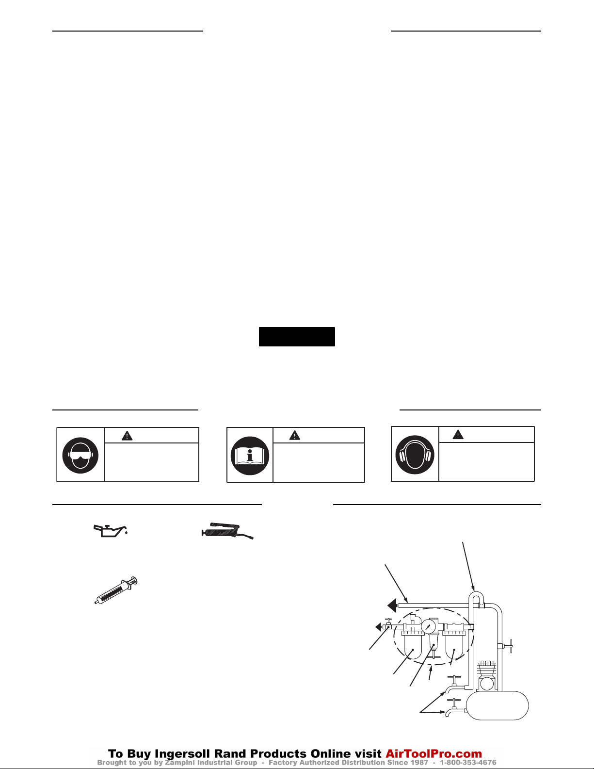
24
VARNINGSSYMBOLENS UTSEENDE
SMÖRJNING
Ingersoll-Rand nr. 50 Ingersoll-Rand nr. 68
Ingersoll-Randvätska,
beställnings nr.
EQ106S-400-1
Efter varje 20,000 cykler, eller i enlighet med vad
erfarenheten säger, skall impulsenhetens drevaggregat
tömmas och fyllas på nytt, enligt anvisningarna i denna
handbok, med hjälp av vätskeutbytesutrustningen
(Best.nr. EQ106S-K400). Smörj sexkantdrevet och
uteffektskaftet före montering.
(Bild. TPD905-2)
Verktygets Användning (Continued)
• Undvik att andas in skadligt damm som kan uppstå vid
arbete med verktygen:
Vissa typer av damm som uppstår vid slipning,
sågning, borrning och andra liknande aktiviteter
innehåller ämnen som orsakar cancer, födelseskador
och andra reproducerbara skador. Exempel på
sådana kemikalier är:
- bly från blybaserade lackfärger,
- kristallint kisel från tegelstenar, cement och andra
murningsprodukter
- arsenik och krom från impregnerat virke.
Hälsorisken på grund av denna exponering varierar,
beroende på hur ofta du utför dessa arbeten. Minska
din exponering för dessa kemikalier genom att arbeta
i välventilerade utrymmen och med godkänd
säkerhetsutrustning, till exempel andningsskydd med
specialfilter för mikroskopiska partiklar.
• Motordrivna verktyg kan vibrera under drift. Vibrationer,
repetitiva rörelser och obekväma arbetsställningar kan
leda till skador på händer och armar. Sluta använda
verktyget och du känner obehag, stickningar eller smärta.
Ta kontakt med läkare innan du fortsätter arbeta med
verktyget.
• Stå stadigt med kroppen i balans. Luta dig inte över
verktyget vid användning. Var beredd på hastiga
förändringar av rörelseriktning, reaktionsmoment och
krafter under start och användning.
• Verktyg och tillbehör kan fortsätta rotera sedan du har
släppt reglaget.
• Undvik ofrivillig start av verktyget genom att se till att det
är avstängt innan du öppnar tryckluftsmatningen. Håll
inte i reglaget när du bär verktyget och släpp reglaget vid
tryckfall.
• Se till att arbetsstycket sitter fast. Använd skruvtving eller
skruvstycke för att hålla fast arbetsstycket, om det går.
• Undvik att bära eller släpa verktyget i slangen.
• Använd inte motordrivna verktyg när du är trött eller
påverkad av läkemedel, droger eller alkohol.
• Använd aldrig skadade verktyg och tillbehör eller verktyg
som inte fungerar som de ska.
• Modifiera inte verktyget, säkerhetsutrustning eller
tillbehör.
• Använd inte det här verktyg för andra ändamål än de som
rekommenderas.
• Använd tillbehör som rekommenderas av Ingersoll-Rand.
• Lägg märke till läget hos omkastarmekanismen innan du
använder verktyget så att du vet åt vilket håll det kommer
att rotera när du öppnar reglaget.
• Använd endast krafthylsor och tillbehör avsedda för
slående verktyg. Använd inte vanliga hylsor och tillbehör.
• Kontrollera verktygshållaren med jämna mellanrum och
förvissa dig om att hylsor och tillbehör ej är alltför slitna,
vilket innebär risk att dessa kan lossna.
Om andra reservdelar än de frn Ingersoll-Rand används, kan detta medföra en säkerhetsrisk, minskad verktygsprestanda och ett
ökat servicebehov. Det kan dessutom få till följd att alla garantier blir ogiltiga.
Reparationer får endast utföras av auktoriserad, utbildad personal. Rådfråga närmaste auktoriserade Ingersoll-Rand
servicecenter.
OBS!
VARNING
Använd alltid skyddsglasögon
när du använder eller utför
service på detta verktyg.
VARNING
Läs denna handbok innan
verktyget används.
VARNING
Använd alltid hörselskydd
när du använder detta
verktyg.
FÖRGRENINGAR,
DUBBELT SÅ STORA
SOM LUFTVERKTYGETS
INTAG
R
S
FRS
F
FILTER
KOMPRESSOR
MATARLEDNINGAR,
TRE GÅNGER SÅ STORA
SOM LUFTVERKTYGETS
INTAG
TILL
LUFT
SYSTEMET
TILL
LUFT
VERKTYGET
NÖDSTOPPSVENTIL
SMÖRJARE
REGULATOR
TÖM REGELBUNDET
Page 25

25
JUSTERINGAR
Justering av Vridmomentet
Följ nedanstående anvisningar för att justera vridmomentet
på dessa dubbelbladiga impulsnycklar:
1. Avlägsna proppen från justeringshålet.
2. Vrid på drevskaftet tills momentjusteringsskruven syns
i öppningen. Momentjusteringsskruven färgmärkning
på skallen.
3. Vrid skruven medurs med antingen en 1,5 mm
sexkantnyckel för att öka utgående moment, moturs för
att minska momentet. Vrid ej på oljeproppen.
4. Sätt tillbaka proppen i justeringshålet.
Gör alla slutliga justeringar på arbetet.
Testad i enlighet PNEUROP PN8NTC1.2
Testad till ISO8662
Modell Ljudstyrkenivå Vibra-
dB(A) tionsnivå
Tryck Kraft m/s
2
40PSQ1 74,4 --- 0,8
45PS3 80,3 --- 0,5
45PSQ1 80,3 --- 0,5
55PS3 81,3 --- 0,7
55PSQ1 81,3 --- 0,7
70PS3 82,7 --- 0,8
90PS4 92,8 --- 1,6
OBS!
Page 26

INNEHOLDER VIKTIG SIKKERHETSINFORMASJON - OPPBEVAR DISSE INSTRUKSJONENE
LES OG SETT DEG INN I DENNE HÅNDBOKEN
FØR DU TAR I BRUK DETTE PRODUKTET
DET ER DITT ANSVAR Å GJØRE DISSE SIKKERHETSINFORMASJONENE
TILGJENGELIGE FOR ANDRE SOM SKAL BRUKE DETTE PRODUKTET
PERSONSKADER KAN OPPSTÅ HVIS
IKKE FØLGENDE ADVARSLER BLIR FULGT
Henvendelser skal rettes til nærmeste Ingersoll-Rand
-avdeling eller -forhandler.
© Ingersoll-Rand Company 2002
Trykt i Japan
• Dette produktet må alltid installeres, brukes, etterses og
vedlikeholdes i henhold til alle gjeldende standarder og
bestemmelser (lokale og nasjonale).
• Bruk alltid ren, tørr luft ved maksimalt lufttrykk på 6,2
bar/620 kPa (90 psig) målt ved luftinntaket. Høyere trykk
kan medføre farlige situasjoner inklusive for høy hastighet,
brudd eller feil dreiemomenteffekt eller kraft.
• Sørg for at alle slanger og koblinger er av riktig størrelse
og er tette. Se tegning TPD905-2 for et typisk
koblingsarrangement.
• Påse at det er installert en tilgjengelig nødstoppventil i
lufttilførselsledningen og sørg for at andre får vite hvor
den befinner seg.
• Bruk ikke en skadet, sprukket eller slitt luftslange/kobling.
• Kom ikke nær piskende luftslanger. Steng av trykkluften
før du nærmer deg en luftslange som ikke er under
kontroll.
• Steng alltid av lufttilførselen og koble fra
lufttilførselslangen før installering, fjerning eller justering
av tilbehør, eller før vedlikehold blir utført på dette
verktøyet.
• Ikke smør verktøy med brennbare eller ustabile væsker
som parafin, diesel eller flybensin. Bruk kun anbefalte
smøremidler.
• Hold arbeidsområdet rent, ryddig, godt luftet og belyst.
• Fjern ikke noen identifikasjonsmerker. Skift ut skadete
merker.
04578084
Form P7528
Edition 3
Juni, 2002
N
HÅNDBOK FOR BRUK OG VEDLIKEHOLD AV MODELL 40PSQ1,
45PS3, 45PSQ1, 55PS3, 55PSQ1, 70PS3 OG 90PS4 DOBBELTBLADEDE
IMPULS-MUTTERTREKKERE MED AUTOMATISK AVSTENGING
Dobbeltskovlede impulsnøkler, modell 40PSQ1, 45PS3, 45PSQ1, 55PS3, 55PSQ1, 70PS3 og 90PS4
er konstruert for monteringsarbeider som krever hurtig tilskruing, konsistent momentrepetering og
redusert momentreaksjon.
FØRSTEGANGSBRUK AV VERKTØY
• Bruk alltid vernebriller under arbeid med eller vedlikehold
av dette verktøy.
• Bruk alltid hørselvern under arbeid med dette verktøy.
•
Bruk alltid personlig verneutstyr tilpasset verktøyet som
brukes og materialet som bearbeides. Dette kan omfatte
støvmaske eller annet åndedrettsvern, vernebriller,
ørepropper, hansker, forkle, vernesko, hjelm og annet
utstyr.
•
Dette verktøyet er ikke konstruert for å brukes i eksplosive
omgivelser, inklusive eksplosjonsfare forårsaket av damp
eller støv, eller i nærheten av brennbare materialer.
• Dette verktøyet er ikke isolert mot elektriske støt.
• Vær oppmerksom på nedgravde, skjulte eller andre farer i
arbeidsmiljøet ditt. Unngå å berøre eller skade ledninger,
kanaler, rør eller slanger som kan inneholde strømførende
ledninger, eksplosive gasser eller skadelige væsker.
• Hold andre på trygg avstand fra arbeidsområdet, eller sørg
for at de bruker egnet personlig verneutstyr.
• Hold hender, løstsittende klær, langt hår og smykker unna
verktøyets virksomme ende.
BRUK AV VERKTØY
MERK
ADVARSEL
Page 27
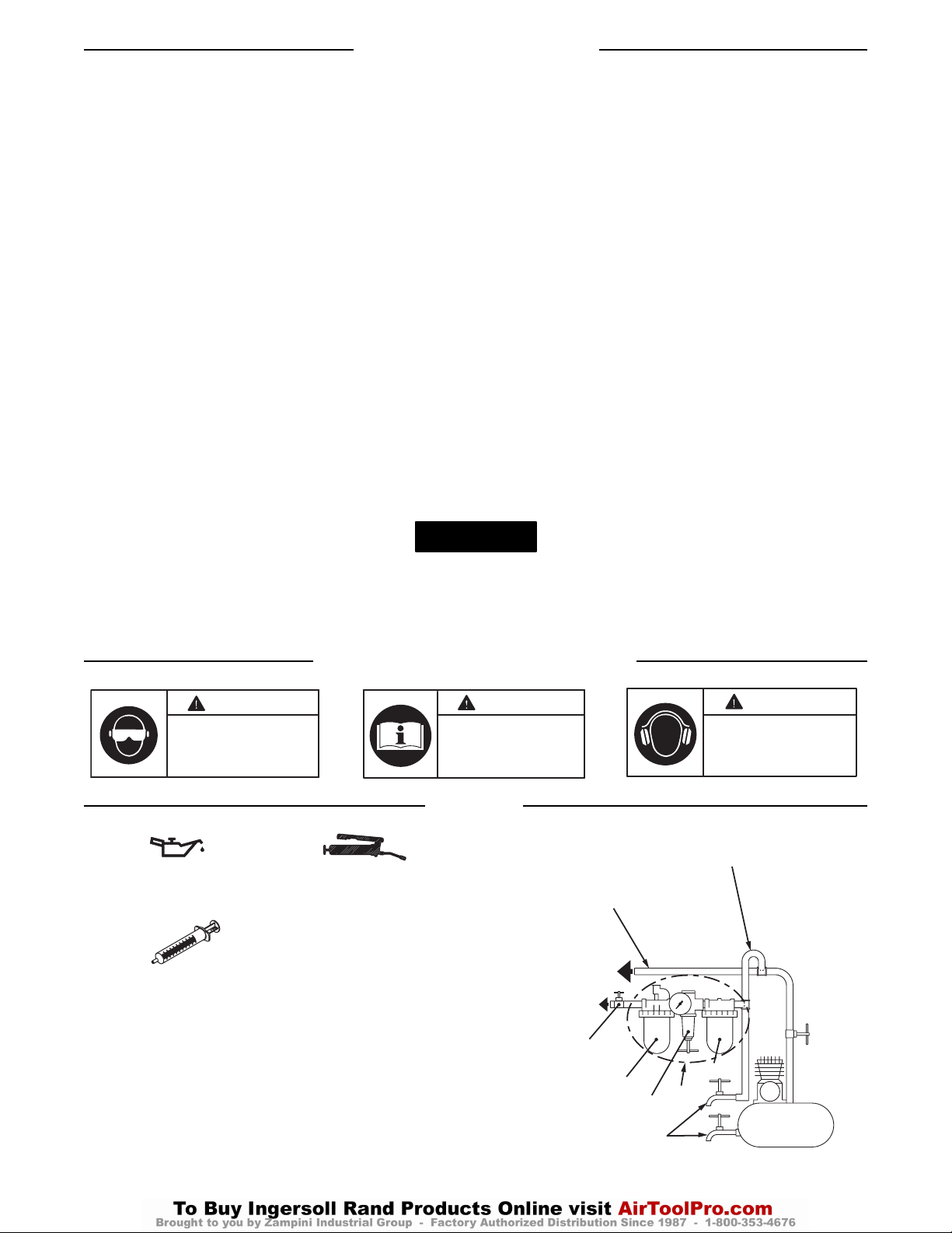
27
BETYDNING AV ADVARSEL-SYMBOL
SMØRING
Ingersoll-Rand nr. 50 Ingersoll-Rand nr. 68
Ingersoll-Rand væske del
nr. EQ106S-400-1
Etter 20 000 sykluser, eller som erfaring tilsier, drener og
påfyll impulsenheten i følge denne instruksjonsboken ved å
bruke væskeskiftutstyret (delenr. EQ106S-K400). Smør
sekskantdrevet og drivakselen før montering.
(Tegning TPD905-2)
Bruk av Verktøy (Continued)
• Unngå eksponering for og innånding av helsefarlig støv og
partikler ved bruk av el- og trykkluftverktøy:
Enkelte typer støv fra pussing, saging, sliping, boring
og andre byggeaktiviteter inneholder kjemikalier som
er kjent for å forårsake kreft, fødselsskader eller |
andre forplantningsskader. Her er noen eksempler på
disse kjemikaliene:
- bly fra blyholdig maling,
- krystallinsk silisiumoksid fra murstein og sement og
andre murprodukter, og
- arsen og krom fra kjemisk behandlet trelast.
Din risiko når det gjelder slik eksponering varierer,
avhengig av hvor ofte du utfører denne typen arbeid.
Slik reduserer du eksponeringen for slike kjemikalier:
Sørg for god ventilasjon på arbeidsplassen, og bruk
godkjent verneutstyr som støvmasker spesielt
konstruert for å filtrere bort mikroskopiske partikler.
• Kraftverktøy kan vibrere ved bruk. Vibrasjon, gjentatte
bevegelser eller ubekvemme stillinger kan være skadelig
for hender og armer. Stans bruken av ethvert verktøy ved
ubehag, stikkende følelser eller hvis du får smerter. Søk
råd fra lege før videre arbeid gjenopptas.
• Sørg for å stå støtt. Ikke forstrekk deg når du bruker dette
verktøyet. Vær forberedt på plutselige endringer i
bevegelse, reaksjonsmoment eller -krefter under start og
bruk.
• Verktøy og/eller tilbehør kan fortsette å bevege seg et kort
øyeblikk etter at pådraget er sluppet.
• For å unngå utilsiktet start - påse at verktøyet er i “av”stilling før du setter på lufttrykk, unngå pådrag når du
bærer verktøyet og slipp pådraget ved lufttap.
• Påse at arbeidsstykkene er sikre. Bruk tvinger eller
skruestikke for å holde arbeidsstykket der det er mulig.
• Ikke bær eller dra verktøyet i slangen.
• Ikke bruk kraftverktøy når du er sliten, eller påvirket av
medisiner, rusmidler eller alkohol.
• Bruk aldri verktøy eller tilbehør som er skadet eller ikke
fungerer som det skal.
• Verktøyet, sikkerhetsanordninger eller tilbehør må ikke
modifiseres.
• Ikke bruk dette producktet til andre formål enn det som
er anbefalt.
• Bruk tilbehør som er anbefalt av Ingersoll-Rand.
• For modeller med revers, vær oppmerksom på
reverseringsmekanismens stilling før verktøyet tas i bruk,
slik at man er klar over i hvilken retning verktøyet roterer
når man bruker pådraget.
• Bruk kun kraftpiper og tilbehør til denne
muttertrekkeren. Ikke bruk piper og tilbehør beregnet for
håndbruk.
• Kontroller jevnlig verktøyets drivende for å sikre at
pipesikringen fungerer som den skal, og at sikringer og
drivender ikke er kraftig slitt, noe som kan medføre at
sikringen løsner når den går rundt.
Bruk av andre deler enn originale Ingersoll-Rand-reservedeler kan føre til sikkerhetsrisiko, redusert verktøy-ytelse og økt
vedlikehold, og kan føre til at garantien blir ugyldig.
Reparasjoner bør bare utføres av godkjent personell. Spør hos ditt nærmeste godkjente Ingersoll-Rand-verksted.
MERK
ADVARSEL
Bruk alltid vernebriller under
arbeid med, eller vedlikehold av
dette verktøy.
ADVARSEL
Les denne
instruksjonshåndboken før
verktøyet tas i bruk.
ADVARSEL
Bruk alltid hørselvern
under arbeid med dette
verktøyet.
AVGRENINGSRØR ER 2
GANGER STØRRE ENN
INNTAKET TIL VERKTØYET
HOVEDRØRET ER 3
GANGER STØRRE
NN INNTAKET TIL VERKTØYET
TIL
LUFTKRETSEN
TIL
VERKTØYET
S
NØDAVSTENGEINGSVENTIL
SMØREENHET
REGULATOR
DRENER MED
JEVNE MELLOMROM
FRS
R
FILTER
F
KOMPRESSOR
Page 28

28
JUSTERINGER
(Dreie) Moment Justeringer
For å justere dreiemomentet på disse dobbeltskovlede
impulsnøklene, følg disse instruksjoner:
1. Ta ut pluggen fra justeringshullet.
2. Roter drivakselen til justeringsskruen for
dreiemomentet blir synlig gjennom åpningen.
Momentjusteringsskruen har farget maling på hodet.
3. Bruk en 1,5 mm sekskantnøkkel og drei
justeringsskruen med urviseren for å øke
dreiemomenteffekten og mot urviseren for å redusere
dreiemomenteffekten. Rotér ikke oljepluggen.
4. Skru pluggen tilbake i justeringshullet.
Gjør alle sluttjusteringene på arbeidsstedet.
Testet i følge PNEUROP PN8NTC1.2
Testet i følge ISO8662
Modell Lydstyrkenivå Vibra-
dB(A) sjonsnivå
Trykk Styrke m/s
2
40PSQ1 74,4 --- 0,8
45PS3 80,3 --- 0,5
45PSQ1 80,3 --- 0,5
55PS3 81,3 --- 0,7
55PSQ1 81,3 --- 0,7
70PS3 82,7 --- 0,8
90PS4 92,8 --- 1,6
MERK
Page 29

OHJEISSA ON MUKANA TÄRKEITÄ TURVAOHJEITA - SÄÄSTÄ NÄMÄ OHJEET
LUE KÄYTTÖOHJEET JA YMMÄRRÄ NE ENNEN KUIN KÄYTÄT TUOTETTA
HUOLEHDI SIITÄ, ETTÄ TURVAOHJEET OVAT
TUOTTEEN MUIDEN KÄYTTÄJIEN SAATAVILLA
SEURAAVIEN VAROITUSTEN LAIMINLYÖMINEN SAATTAA JOHTAA VAMMAUTUMISEEN
Osoita mahdollinen kirjeenvaihto lähimpään
Ingersoll-Randin toimistoon tai jälleenmyyjälle.
© Ingersoll-Rand Company 2002
Painettu Japanissa
• Noudata kaikkia tuotteen asennusta, käyttöä, tarkastuksia
ja huoltoa koskevia määräyksiä.
• Käytä aina puhdasta, kuivaa paineilmaa, jonka tulopaine
on enintään 6,2 bar/620 kPa (90 psig). Suuremman
paineen käyttäminen voi aiheuttaa vaaratilanteita (liian
suuri nopeus, repeämä tai väärä momentti tai voima).
• Varmistu, että kaikki paineilmaletkut ja -liittimet ovat
oikeaa kokoa ja ne ovat tiiviisti kiinni. Katso kuvasta
TPD905-2 kaaviota tavanomaisesta paineilmakytkennästä.
• Varmista, että ilmalinjassa on hätäsulkuventtiili helposti
löytyvässä paikassa, ja tiedota sen sijainnista.
• Älä käytä vahingoittuneita, hankautuneita tai kuluneita
paineilmaletkuja tai -liittimiä.
• Varo heiluvia ilmaletkuja. Sulje paineilman syöttö ennen
kuin lähestyt nopeasti heiluvaa letkun päätä.
• Kytke paineilma aina pois päältä ja irroita paineilmaletku
ennen kuin asennat, poistat tai säädät mitään tämän
työkalun lisälaitetta tai ennen kuin alat huoltaa työkalua.
• Älä voitele työkalua tulenaroilla tai helposti haihtuvilla
nesteillä, kuten dieselöljyllä, kerosiinilla tai Jet-A polttoaineella. Käytä vain suositeltuja voiteluaineita.
• Pidä työtila puhtaana, siistinä, tuuletettuna ja valaistuna.
• Älä poista mitään työkalussa olevia tarroja. Vaihda
vahingoittuneet tarrat.
04578084
Kaavake P7528
Versio 3
Kesakuu, 2002
FIN
KAKSILAMELLISET PYSÄHTYVÄT IMPULSSIAVAIMET
40PSQ1, 45PS3, 45PSQ1, 55PS3, 55PSQ1, 70PS3 JA 90PS4
KÄYTTÖ- JA HUOLTO-OHJEET
40PSQ1, 45PS3, 45PSQ1, 55PS3, 55PSQ1, 70PS3 ja 90PS4 -sarjan impulssivääntimet on tarkoitettu
käytettäväksi sellaisissa kokoonpanotöissä, jotka vaativat mahdollisimman nopeaa
kiinnityskappaleiden kiinnikiertämistä mahdollisimman vakiolla vääntömomentilla ja
mahdollisimman vähäisellä vääntömomentin reaktiovoimalla.
TYÖKALUJEN KÄYTTÖÖNOTTO
•
Käytä aina suojalaseja työkalua käyttäessäsi tai
huoltaessasi.
• Käytä aina kuulosuojaimia työkalua käyttäessäsi.
• Käytä työkalun ja materiaalin edellyttämiä
henkilökohtaisia suojavarusteita: pölynaamari tai muu
hengityslaite, suojalasit, kuulonsuojaimet, käsineet, esiliina,
turvakengät, kypärä ja muut suojaimet.
• Työkalua ei ole tarkoitettu räjähtäviin ympäristöihin, ei
myöskään huuruisiin tai pölyisiin oloihin, eikä
käytettäväksi lähellä palavia materiaaleja.
•
Tämä työkalu ei ole eristetty sähköiskujen varalta.
• Varo työympäristön piileviä vaaroja. Älä kosketa tai
vaurioita johtoja, putkia tai letkuja, joissa voi olla
sähköjohtimia, räjähtäviä kaasuja tai haitallisia nesteitä.
•
Pidä sivulliset riittävän etäällä tai varmista, että he
käyttävät tarvittavia suojavarusteita.
• Pidä kädet, löysät vaatteet, pitkät hiukset ja korut pois
työkalun toimivasta päästä.
TYÖKALUN KÄYTTÖ
HUOMAA
VAROITUS
Page 30
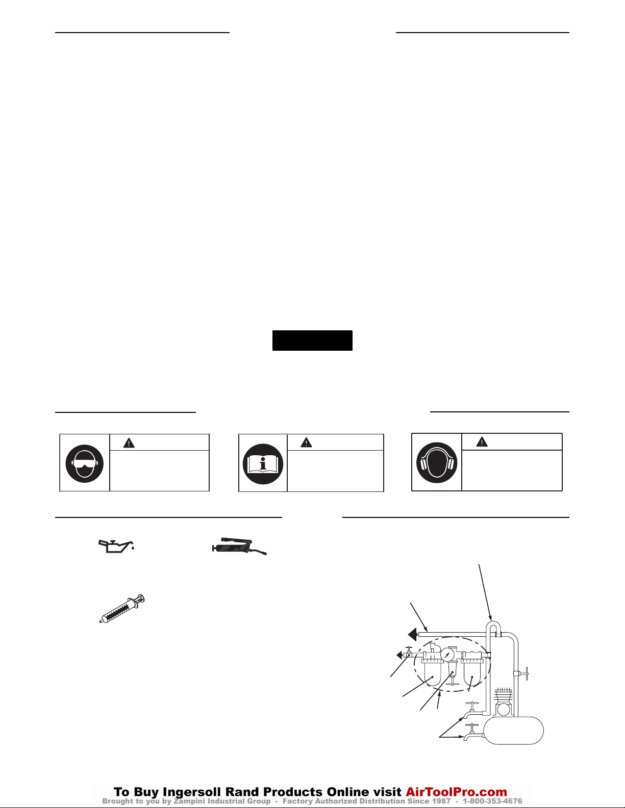
30
VAROITUSSYMBOLIEN TUNNISTAMINEN
VOITELU
Ingersoll-Rand 50 Ingersoll-Rand 68
Ingersoll-Rand Öljysarja
EQ106S-400-1
Tyhjennä ja täytä impulssiyksikön vetolaitteen kokoonpano
tässä ohjekirjassa annettujen neuvojen mukaisesti aina 20
000 jakson välein tai käyttökokemuksiesi mukaan. Käytä
öljynvaihtosarjaa (osanumero OQ106S-K400). Voitele
kuusioakseli ja ulostuloakseli ennen kuin kokoat laitteen
uudestaan.
(Kuva TPD905-2)
Työkalun Käyttö (Continued)
• Vältä altistuminen haitalliselle pölylle ja hiukkasille sekä
pölyn ja hiukkasten hengittäminen käyttäessäsi koneita:
Hiottaessa, sahattaessa, porattaessa ja käsiteltäessä
muuten rakennusmateriaaleja vapautuu pölyä, jonka
sisältävien kemikaalien tiedetään aiheuttavan syöpää,
syntymävikoja ja muita lisääntymishäiriöitä.
Esimerkkejä tällaisista kemikaaleista:
- lyijyperustaisten maalien lyijy,
- silikaatti tiilistä, sementistä ja muista kivituotteista A
- aseeni ja kromi kemiallisesti käsitellystä
puutavarasta.
Altistusriski vaihtelee sen mukaan, kuinka usein
tällaista työtä tekee. Suojaudu tällaisilta
kemikaaleilta: työskentele hyvin tuuletetussa tilassa.
Käytä hyväksyttyjä suojaimia, esimerkiksi
pölynaamareita, jotka on nimenomaisesti suunniteltu
suodattamaan mikroskooppiset hiukkaset.
• Työkalut voivat täristä. Tärinä, toistuvat liikesarjat tai
epämiellyttävät asennot saattavat olla vahingollisia käsille
ja käsivarsille. Lopeta työkalun käyttö, jos alat tuntea
kihelmöintiä ja kipua. Käänny lääkärin puoleen ennen
kuin jatkat työkalun käyttöä.
• Seiso tukevasti. Älä kurkottele, kun käytät työkalua. Varo
äkkinäisiä liikkeen muutoksia, reaktiovoimia ja voimia,
kun käynnistät ja käytät työkalua.
• Työkalut ja/tai varusteet voivat jatkaa liikkumista hetken
aikaa liipaisimen vapauttamisen jälkeen.
• Estä käynnistyminen vahingossa - varmista ennen ilman
kytkemistä, että työkalu on “pois”, varo liipaisinta
kantaessasi työkalua, ja vapauta liipaisin paineen
hävitessä.
• Varmista, että työkappaleet ovat tukevasti paikallaan.
Käytä puristimia tai ruuvipenkkiä aina, kun se on
mahdollista.
• Älä kanna työkalua letkun varassa.
• Älä käytä työkaluja väsyneenä eikä lääkkeiden,
huumeiden tai alkoholin vaikutuksen alaisena.
• Älä käytä vaurioitunutta tai väärin toimivaa työkalua tai
varustetta.
• Älä muuta työkalua, turvalaitteita tai varusteita.
• Käytä tuotetta vain suositeltuun tarkoitukseen.
• Käytä Ingersoll-Randin suosittelemia lisälaitteita.
• Huomaa suunnanvaihtolaitteen asento ennen kuin käytät
työkalua, jotta tiedät pyörimissuunnan, kun painat
käynnistysvipua.
• Käytä iskevään mutterinvääntimeen tarkoitettuja hylsyjä
ja varusteita. Älä käytä käsityökaluihin tarkoitettuja
(kromattuja) hylsyjä tai varusteita.
• Tarkasta säännöllisesti, että hylsyn pidin toimii kunnolla,
ja että hylsyt tai vääntiötapit eivät ole kuluneet niin paljon,
että hylsy voi irrota pyöriessään.
Muiden kuin Ingersoll-Randin alkuperäisvaraosien käyttö saattaa johtaa vaaratilanteisiin, heikentyneisiin työkalun
suoritusarvoihin, kasvavaan huollontarpeeseen ja se saattaa mitätöidä kaikki takuut.
Ainoastaan valtuutetun, koulutetun henkilöstön tulisi korjata työkalua. Lisätietoja saat lähimmästä Ingersoll-Randin
merkkihuoltokeskuksesta
.
HUOMAA
VAROITUS
Käytä aina suojalaseja työkalua
käyttäessäsi tai huoltaessasi.
VAROITUS
Lue tämä ohjekirja ennenkuin
alat käyttää työkaluja.
VAROITUS
Käytä aina kuulosuojaimia
työkalua käyttäessäsi.
PAINEILMAN HAARALINJA
LÄPIMITALTAAN KAKSI KERTAA
PAINEILMATYÖKALUN
LIITINAUKON KOKOINEN
PÄÄPAINEILMALINJA
LÄPIMITALTAAN KOLME
KERTAA PAINEILMATYÖKALUN
LIITINAUKON KOKOINEN
PAINEILMAJÄRJESTELMÄÄN
PAINEILMATYÖKALUUN
HÄTÄPYSÄYTYSVENTTIILI
VOITELUYKSIKKÖ
PAINEENSÄÄDIN
TYHJENNÄ
SÄÄNNÖLLISESTI
V
SPV
P
S
SUODATIN
KOMPRESSORI
Page 31

31
SÄÄDÖT
Momentin Saato
Toimi seuraavasti säätääksesi näiden kaksilamellisten
impulssivääntimien vääntömomenttia:
1. Irroita säätöreiän tulppa.
2. Kierrä vetoakselia, kunnes vääntömomentin säätöruuvi
tulee näkyviin aukosta. Momentinsäätöruuvin
kannassa ei värillistä maalia.
3. Käännä säätöruuvia 1,5 mm kuusiokoloavaimella
myötäpäivään, kun haluat suurentaa momenttia, tai
vastapäivään, kun haluat pienentää momenttia. Älä
kierrä öljytulppaa kumpaankaan suuntaan.
4. Pistä säätöreiän tulppa takaisin paikalleen.
Tee kaikki lopulliset säädöt vasta työtä
tehdessäsi.
Koestettu PNEUROP PN8NTC1.2
Koestettu ISO8662
Malli Melutaso Värinä
dB(A)
Paine Teho m/s
2
40PSQ1 74,4 --- 0,8
45PS3 80,3 --- 0,5
45PSQ1 80,3 --- 0,5
55PS3 81,3 --- 0,7
55PSQ1 81,3 --- 0,7
70PS3 82,7 --- 0,8
90PS4 92,8 --- 1,6
HUOMAA
Page 32
INFORMAÇÃO DE SEGURANÇA IMPORTANTE EM ANEXO - GUARDE ESTAS INSTRUÇÕES
LEIA E COMPREENDA ESTE MANUAL ANTES DE OPERAR ESTE PRODUTO
É SUA RESPONSABILIDADE PÔR ESTAS INFORMAÇÕES DE SEGURANÇA À
DISPOSIÇÃO DAS OUTRAS PESSOAS QUE IRÃO OPERAR ESTE PRODUTO
O NÃO CUMPRIMENTO DAS SEGUINTES ADVERTÊNCIAS
PODE RESULTAR EM FERIMENTOS
Envie Todos os Comunicados Para o Distribuidor
ou Escritório da Ingersoll-Rand Mais Próximo.
© Ingersoll-Rand Company 2002
Fabricado no Japão
• Instale, opere, inspeccione e faça manutenção neste produto
sempre de acordo com todas as normas e regulamentos
aplicáveis (locais, estatais, federais, nacionais etc.).
• Utilize sempre ar limpo e seco a uma pressão máxima de 6,2
bar na admissão. Pressão mais alta pode resultar em
situações perigosas incluindo velocidade excessiva, ruptura ou
binário ou força de saída incorrectos.
• Certifique-se de que todas as mangueiras e acessórios são da
dimensão correcta e que estão seguros firmemente. Consulte o
Des. TPD905-2 para uma disposição de tubos típica.
• Certifique-se de que foi instalada uma válvula de isolamento
de emergência acessível na linha de alimentação de ar e
informe os outros sobre a sua localização.
• Não utilize mangueiras de ar e acessórios danificados, puídos
ou deteriorados.
• Mantenha-se afastado de mangueiras de ar a chicotear.
Desligue o compressor antes de se aproximar de uma
mangueira de ar a chicotear.
• Desligue sempre a alimentação de ar e a mangueira de
alimentação de ar antes de instalar, retirar ou ajustar
qualquer acessório desta ferramenta, ou antes de fazer
manutenção na mesma.
• Não lubrifique a ferramenta com líquidos inflamáveis ou
voláteis como querosene, gasóleo ou combustível para jactos.
Utilize apenas os lubrificantes especificados.
• Mantenha a área de trabalho limpa, em ordem, ventilada e
bem iluminada.
• Não retire nenhum rótulo. Substitua os rótulos danificados.
04578084
Form P7528
Edição 3
Junho, 2002
P
MANUAL DE FUNCIONAMENTO E MANUTENÇÃO PARA AS CHAVES
DE IMPULSO DE DESLIGAMENTO AUTOMçTICO COM DUAS PALHETAS
MODELOS 40PSQ1, 45PS3, 45PSQ1, 55PS3, 55PSQ1, 70PS3 E 90PS4
As Ferramentas Pneumáticas de Impulso Modelos 40PSQ1, 45PS3, 45PSQ1, 55PS3, 55PSQ1,
70PS3 e 90PS4 são concebidas para operações de montagem que exijam velocidade de aperto
elevada com torque exercido consistente e reacção de torque reduzida.
COLOCANDO A FERRAMENTA EM FUNCIONAMENTO
• Use sempre protecção para os olhos ao operar ou fazer
manutenção nesta ferramenta.
• Use sempre protecção auricular ao operar esta ferramenta.
•
Utilize sempre equipamento de protecção pessoal apropriado
para a ferramenta utilizada e o material de trabalho. Isso pode
incluir máscara contra a poeira ou outro aparelho de
respiração, óculos de segurança, auriculares, luvas, avental,
calçado de segurança, capacete e outro equipamento.
• Esta ferramenta não é concebida para trabalhar em ambientes
explosivos, incluindo os provocados por vapores e poeira ou
perto de materiais inflamáveis.
• Esta ferramenta não é isolada contra choque eléctrico.
• Tenha em conta a possível presença de perigos enterrados,
ocultos e outros no seu ambiente de trabalho. Não contacte ou
danifique cabos, condutas, tubos ou mangueiras que possam
conter fios eléctricos, gases explosivos ou líquidos perigosos.
• Mantenha terceiros a uma distância segura da sua área de
trabalho ou certifique-se de que os mesmos estão a usar
equipamento de protecção pessoal.
• Mantenha as mãos, roupas soltas, cabelos longos e jóias
afastados da extremidade de trabalho da ferramenta.
USANDO A FERRAMENTA
AVISO
ADVERTÊNCIA
Page 33
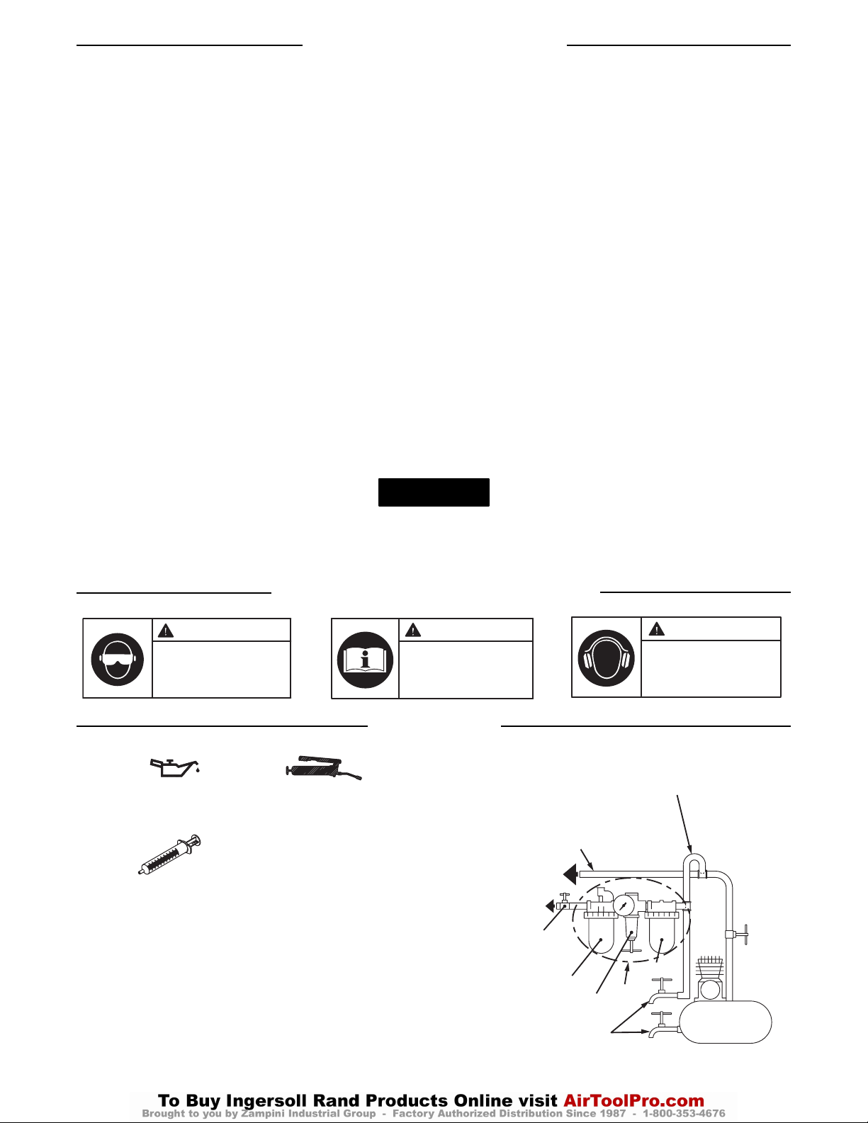
33
IDENTIFICAÇÃO DO SÍMBOLO DE AVISO
LUBRIFICAÇÃO
Ingersoll-Rand No. 50 Ingersoll-Rand No. 68
Fluído Ingersoll-Rand
Número de Pedido
EQ106S-400-1
Depois de cada 20 000 ciclos, ou como a experiência
indicar, drene e encha o Conjunto do Comando da Unidade
de Impulso como instruído neste manual usando o Kit de
Reposição de Fluido (Número de Pedido EQ106S-K400).
Lubrifique o comando hexagonal e o eixo de saída antes de
montar.
(Desenho TPD905-2)
Usando a Ferramenta (Continued)
• Evite expor-se e respirar as poeiras e partículas nocivas
criadas pela utilização de ferramentas motorizadas:
Algumas poeiras criadas por operações motorizadas de
lixar, serrar, rectificar, perfurar e outras actividades de
construção contêm produtos químicos conhecidos por
causarem cancro, malformações congénitas e terem
efeitos nocivos na reprodução. Alguns exemplos desses
produtos químicos são:
- chumbo de tintas à base de chumbo,
- sílica cristalina de tijolos e cimento e outros produtos de
alvenaria e
- arsénico e crómio de madeira tratada quimicamente
Os riscos dessas exposições varia, dependendo de com
que frequência faz esse tipo de trabalho. Para reduzir a
sua exposição a esses produtos químicos: trabalhe numa
área bem ventilada e com equipamento de segurança
aprovado, como as máscaras contra a poeira que são
especialmente projectadas para filtrar partículas
microscópicas.
• As ferramentas mecânicas podem vibrar durante a utilização.
Vibração, movimentos repetitivos ou posições desconfortáveis
podem ser nocivos às suas mãos e braços. Pare de utilizar
qualquer ferramenta se sentir desconforto, sensação de
formigueiro ou dor. Procure assistência médica antes de
reiniciar a utilização.
• Mantenha o corpo numa posição equilibrada e firme. Não
estique o corpo ao operar esta ferramenta. Esteja preparado e
alerta para mudanças súbitas no movimento, binários ou
forças de reacção durante o arranque e o funcionamento.
• A ferramenta e/ou acessórios podem continuar o movimento
por um curto período depois que o regulador é libertado.
• Para evitar o arranque acidental, certifique-se de que a
ferramenta está na posição desligada (“off”) antes de aplicar
pressão de ar, evite apertar o regulador ao transportar a
ferramenta e liberte o regulador durante a perda de ar.
• Certifique-se de que as peças de trabalho estão seguras.
Sempre que possível, utilize grampos ou tornos para fixar a
peça de trabalho.
• Não transporte ou arraste a ferramenta pela mangueira.
• Não utilize ferramentas mecânicas quando estiver cansado ou
sob a influência de drogas, álcool ou medicamentos.
• Nunca utilize uma ferramenta ou acessório avariado ou a
funcionar mal.
• Não modifique a ferramenta, os dispositivos de segurança ou
os acessórios.
• Não utilize esta produto para fins diferentes dos
recomendados.
• Use os acessórios recomendados pela Ingersoll-Rand.
• Para os modelos reversíveis, note a posição do mecanismo de
inversão antes de operar a ferramenta de forma a estar ciente
da direcção de rotação ao operar o regulador.
• Use apenas caixas e acessórios de chave de percussão nesta
ferramenta de percussão. Não use caixas ou acessórios
manuais(cromo).
• Periodicamente, examine a extremidade de accionamento da
ferramenta para assegurar que o retentor de caixa funciona
correctamente e que as extremidades de accionamento não
estão excessivamente desgastadas, o que pode permitir que a
caixa se solte durante a rotação.
O uso de peças de substituição que não sejam genuinamente da Ingersoll-Rand podem resultar em riscos de segurança, diminuição do
desempenho da ferramenta, aumento da necessidade de manutenção e pode invalidar todas as garantias.
As reparaçıes devem ser feitas somente por pessoal treinado autorizado. Consulte o Centro de Serviços da Ingersoll-Rand mais próximo.
AVISO
ADVERTÊNCIA
Use sempre protecção para os
olhos ao operar ou fazer
manutenção nesta ferramenta.
ADVERTÊNCIA
Leia este manual antes de
operar a ferramenta.
ADVERTÊNCIA
Use sempre protecção
auricular ao operar esta
ferramenta.
LINHA RAMIFICADA 2
VEZES O TAMANHO DA
ENTRADA DA FERRAMENTA
PNEUMÁTICA
PARA
SISTEMA DE AR
PARA
FERRAMENTA
PNEUMÁTICA
LINHAS PRINCIPAIS 3
VEZES O TAMANHO DA
ENTRADA DA FERRAMENTA
PNEUMÁTICA
VÁLVULA DE
ISOLAMENTO
DE EMERGÊNCIA
LUBRIFICADOR
REGULADOR
DRENE
REGULARMENTE
R
L
FRL
F
FILTRO
COMPRESSOR
Page 34

34
AJUSTES
Ajuste de Torque
Para ajustar o torque nestas Chaves Dinamométricas de
Impulsão de Lâminas Duplas, proceda da seguinte maneira:
1. Remova o Bujão do Furo de Ajuste.
2. Gire o Eixo de Comando até o Parafuso de Ajuste de
Torque estar visível abertura.
3. Com uma chave sextavada de 1,5 mm, rode o Parafuso
de Ajuste para a direita para aumentar o valor de
binário e para a esquerda para diminuir o valor de
binário. Não gire o Bujão de Óleo.
4. Reponha o Bujão do Furo de Ajuste.
Faça todos os ajustes finais no serviço.
Testada de acordo com a PNEUROP PN8NTC1.2
Testada de acordo com a ISO8662
Modelo Nível de Ruído Nível de
dB(A) Vibrações
Pressão Potência m/s
2
40PSQ1 74,4 --- 0,8
45PS3 80,3 --- 0,5
45PSQ1 80,3 --- 0,5
55PS3 81,3 --- 0,7
55PSQ1 81,3 --- 0,7
70PS3 82,7 --- 0,8
90PS4 92,8 --- 1,6
AVISO
Page 35
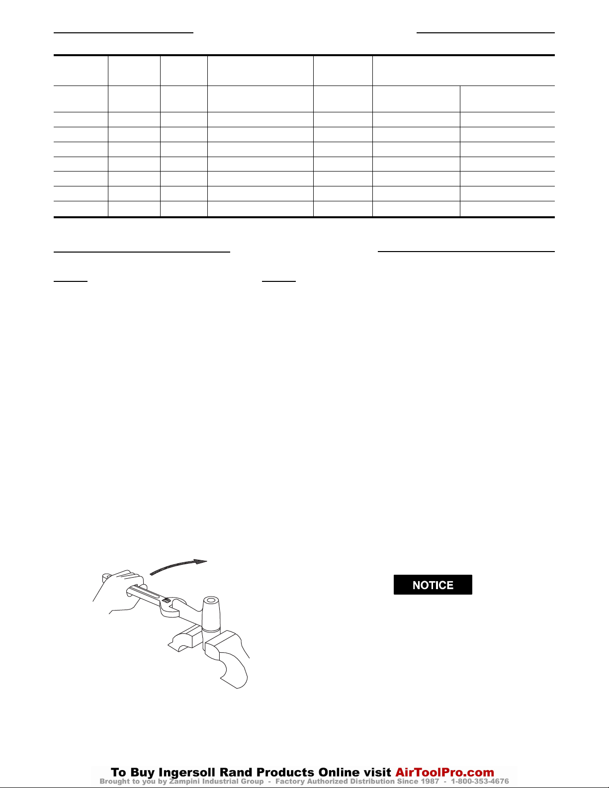
35
HOW TO ORDER AN IMPULSE WRENCH
Changing the Mechanism Fluid
To change the Mechanism Fluid in the Impulse Mechanism,
proceed as follows:
1. For Models 40PSQ1, 45PSQ1 or 55PSQ1, use a
pointed probe to push the Spring Seat (103) against the
Retaining Sleeve Spring (102). While the Sleeve is
compressed, use another pointed probe or thin blade
screwdriver to remove the Retaining Ring (104). Lift
the Spring Seat, the Spring and the Bit Retaining
Sleeve (101) off the Drive Shaft (75) and remove the
Bit Retaining Ball (100).
❑ Continue here for Models 40PSQ1, 45PSQ1 and
55PSQ1
➢ Step 1 for Models 45PS3 and 55PS3
Using copper-covered vise jaws, carefully grasp the
Flats of the Hammer Case (98) with the output end of
the Drive Shaft downward.
2. Using an adjustable wrench, unscrew the Motor
Housing Assembly (1) from the Hammer Case. This is
a left-handed thread, rotate the Motor Housing
clockwise to remove it. (Refer to Dwg. TPD1264)
(Dwg. TPD1264)
3. Lift the assembled motor off the Hammer Case and
pull the mechanism assembly out of the Cover.
❑ Go to Step 4 for Models 40PSQ1, 45PS3,
45PSQ1, 55PS3 and 55PSQ1
➢ Step 1 for Models 70PS3 and 90PS4
Using a hex wrench, remove the 4 Hammer Case
Screws (107) and Lock Washers (106). Lift the
Hammer Case (98) off the Motor Housing over the
Drive Shaft. Remove the Hammer Case Gasket (108).
4. With the assembled mechanism off of the Rotor, use
Oil Plug Wrench to unscrew and remove the Oil Plug
(85) and Oil Plug Seal (84) from the front end of the
Mechanism.
5. Using the 1.5 mm hex wrench (F) furnished with the
tool, rotate the Torque Adjustment Screw identified
with yellow paint counterclockwise until it stops. This
screw adjusts the check valve.
6. With the oil plug opening downward over a container,
rotate the Drive Shaft to purge the fluid from the
mechanism.
7. Using the syringe and fluid from the Fluid
Replacement Kit (Part No. EQ106S-K400), fill the
mechanism with the fluid furnished with the Kit until
the fluid overflows the fill hole.
(Refer to Dwg. TPD1265.)
DO NOT SUBSTITUTE ANY OTHER FLUID.
Failure to use the impulse mechanism fluid provided
could damage the tool, increase maintenance and
decrease performance. Use only clean fluid in these tools.
MAINTENANCE SECTION
Model Handle Drive
Recommended Free Speed
Recommended Torque Range
Hose ID
in. in. (rpm)
Soft Draw Hard Draw
Nm (ft-lb) Nm (ft-lb)
40PSQ1 pistol 1/4 hex .250 5000 5-10 (3.7-7.4) 8-13 (5.9-9.6)
45PS3 pistol 3/8 sq .250 7000 8-15 (5.9-11.1) 13-20 (9.6-14.2)
45PSQ1 pistol 1/4 hex .250 7000 7-13 (5.2-9.6) 11-17 (8.1-12.6)
55PS3 pistol 3/8 sq .250 6000 10-20 (7.4-14.8) 10-28 (11.8-20.7)
55PSQ1 pistol 1/4 hex .250 6000 8-15 (5.9-11.1) 13-22 (9.6-16.2)
70PS3 pistol 3/8 sq .375 5500 36-47 (26.6-34.7) 37-58 (27.3-41.8)
90PS4 pistol 1/2 sq .375 5000 51-78 (37.6-57.6) 59-80 (43.5-59)
CLOCKWISE TO LOOSEN
Page 36
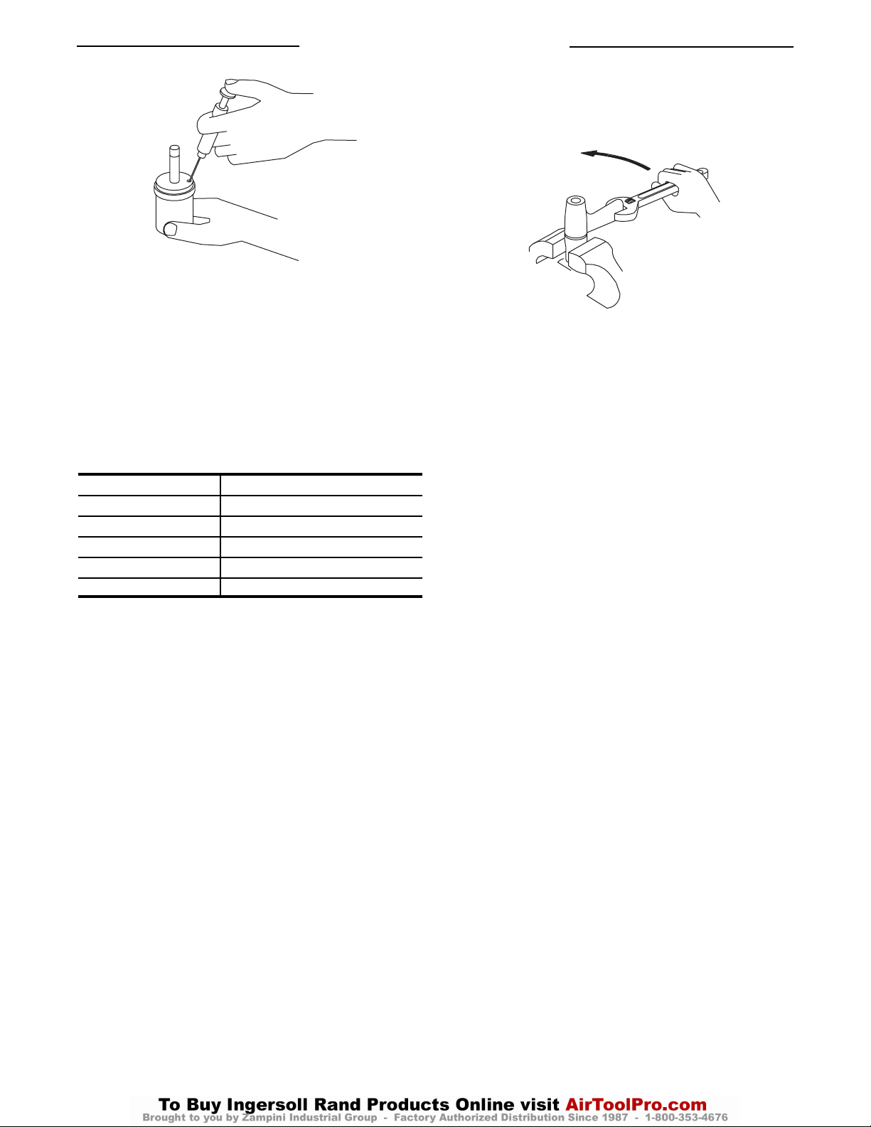
36
Maintenance Section (Continued)
(Dwg. TPD1265)
8. Submerge the mechanism in a reservoir containing
mechanism fluid, and using a wrench, rotate the Drive
Shaft clockwise and counterclockwise to purge any
remaining air from the system.
9. Remove the mechanism from the fluid and rotate the
Adjustment Screw clockwise until it stops.
10. Thread the Oil Plug with the Oil Plug Seal into the
mechanism until it is snug.
11. Wipe the outside of the mechanism dry and clean and
remove the Oil Plug. Using the syringe, withdraw:
Model Withdraw Fluid (cc)
40PSQ1 0.15-0.20
45PS3 & 45PSQ1 0.30-0.35
55PS3 & 55PSQ1 0.30-0.35
70PS3 0.50-0.55
90PS4 0.75-0.80
12. Install the Oil Chamber Plug and tighten it between 20
and 25 in-lb (2.3 and 2.8 Nm) torque.
❑ For Models 70PS3 and 90PS4 apply the
following 2 steps (13 and 14)
13. Position a new Hammer Case Gasket (103) on the
Motor Housing (1) and install the assembled
mechanism on the rotor shaft.
14. Place the Hammer Case over the Drive Shaft against
the Housing and Gasket. Install the (4) four Hammer
Case Cap Screws and Lock Washers. Tighten each
Screw between 45 and 50 in-lb (5.1 and 5.6 Nm) torque.
❑ For Models 40PSQ1, 45PS3, 45PSQ1, 55PS3
and 55PSQ1 apply the following 3 steps
(15, 16 and 17)
15. Install the Oil Chamber Plug and tighten it between 20
and 25 in-lb (2.3 and 2.8 Nm) torque.
16. Insert the mechanism assembly (with output end
leading) into the Mechanism Cover clamped in the vise
jaws.
17. Insert the hex end of the rotor shaft into the hex recess
at the rear of the Drive Shaft and thread the assembled
Motor Housing onto the Mechanism.
(Dwg. TPD1266)
18. For Models 40PSQ1, 45PSQ1 AND 55PSQ1, insert
Bit Retaining Ball into the hole in the Drive Shaft.
Place Bit Retaining Sleeve Spring and Spring Seat
onto the Drive Shaft. While compressing the Spring
Seat against the Spring, install the Retaining Ring onto
the Drive Shaft.
❑ Now continue for all (7) seven Models
19. Test the tool for torque at maximum, minimum and
mid-range torque settings. If the tool does not perform
satisfactorily, repeat the refill procedure and pay
particular attention to removing unwanted air from the
fluid system. Refer to the section TORQUE
ADJUSTMENT for specific adjustment procedures.
20. If the torque is satisfactory but the tool fails to shutoff, only then, is it necessary to adjust the shut-off
mechanism. If it should become necessary, proceed as
follows:
a. Remove the Socket Plug (99) from the Hammer
Case.
b. Rotate the Drive Shaft until the Shutoff Adjustment
Screw (located 180 degrees from the yellow Torque
Adjustment Screw) is visible. This screw adjusts
the relief valve.
c. Rotate the Shutoff Adjustment Screw counter-
clockwise not more than 10 degrees. Adjustments
to this screw should never exceed five to ten degree
increments.
d. Replace the Socket Plug and re-test the pulse tool.
COUNTERCLOCKWISE TO TIGHTEN
Page 37
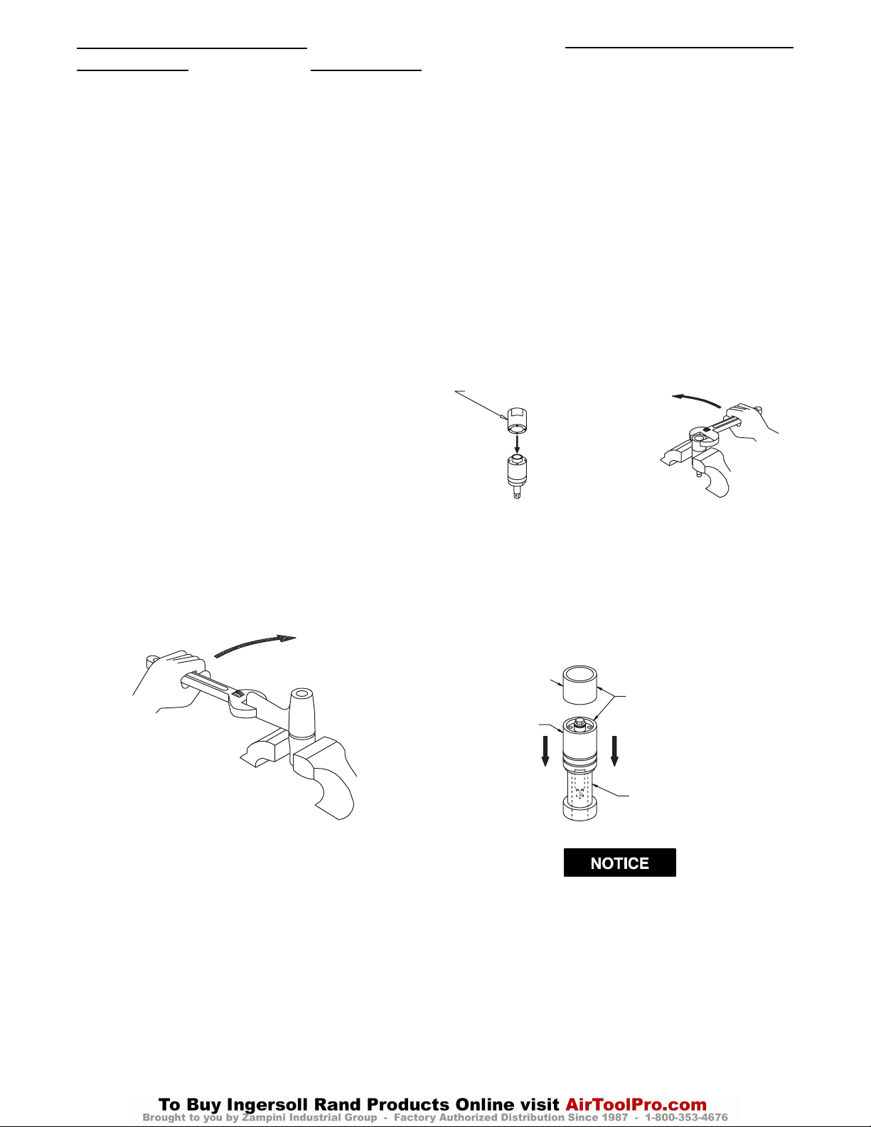
37
Maintenance Section (Continued)
Disassembly
General Instructions
1. Do not disassemble the tool any further than necessary
to replace or repair damaged parts.
2. When grasping a tool or part in a vise, always use
leather-covered or copper-covered vise jaws to protect
the surface of the part and help prevent distortion. This
is particularly true of threaded members and housings.
3. Do not remove any part which is a press fit in or on an
assembly unless the removal of that part is necessary
for repairs or replacement.
Disassembly of the Impulse Mechanism
1. For Models 40PSQ1, 45PSQ1 or 55PSQ1, use a
pointed probe to push the Spring Seat (103) against the
Retaining Sleeve Spring (102). While the Sleeve is
compressed, use another pointed probe or thin blade
screwdriver to remove the Retaining Ring (104). Lift
the Spring Seat, the Spring and the Bit Retaining
Sleeve (101) off the Drive Shaft (75) and remove the
Bit Retaining Ball (100).
❑ Continue here for Models 40PSQ1, 45PSQ1 and
55PSQ1
➢ Step 1 for Models 45PS3 and 55PS3
Using copper-covered vise jaws, carefully grasp the
Flats of the Hammer Case (98) with the output end of
the Drive Shaft downward.
2. Using an adjustable wrench, unscrew the Motor
Housing Assembly from the Hammer Case. This is a
left-handed thread, rotate the Motor Housing clockwise
to remove it. (Refer to Dwg. TPD1264.)
(Dwg. TPD1264)
3. Lift the assembled motor off the Hammer Case and
pull the mechanism assembly out of the Cover.
❑ Go to step 4 for Models 40PSQ1, 45PSQ1,
55PSQ1, 45PS3 and 55PS3
➢ Step 1 for Models 70PS3 and 90PS4
Using a hex wrench, remove the 4 Hammer Case
Screws (107) and Lock Washers (106). Lift the
Hammer Case (98) off the Motor Housing over the
Drive Shaft. Remove the Hammer Case Gasket (108).
4. With the assembled mechanism off of the Rotor, use
Oil Plug Wrench to unscrew and remove the Oil Plug
(85) and Oil Plug Seal (84) from the front end of the
Mechanism.
5. Using the 1.5 mm hex wrench (F) furnished with the
tool, rotate the Torque Adjustment Screw identified
with yellow paint, counterclockwise until it stops.
6. With the oil plug opening downward over a container,
rotate the Drive Shaft to purge the fluid from the
mechanism.
7. Insert the pins of the Spanner Plug from the 45PS-99
(or from the 90PS-99 in the case of Model No. 90PS4),
Tool Kit into the holes provided in the Housing Cap
(56). Using a wrench on the plug, unscrew and remove
the Housing Cap from the Liner Case. (Refer to Dwg.
TPD1267.)
NOTE: An adhesive agent is used on Models 70PS3 and
90PS4.
(Dwg. TPD1267)
8. Stand the Disassembly Arbor from the Tool Kit, with
large end downward, on a workbench or on the table of
an arbor press. Insert the output end of the Drive Shaft
into the central opening and either tap the Liner Case
downward off the components or use the Pressing
Sleeve in the Kit to press the Liner Case downward off
the components. (Refer to Dwg. TPD1268.)
(Dwg. TPD1268)
In the following step, do not remove or turn the Shut-off
Adjustment Screw located in the Front Liner Cover. It
is the Screw located 180 from the yellow torque
adjustment screw.
9. Disassemble the components of the mechanism in the
sequence shown in Drawings, refer to Parts List
section to locate specific Model drawings.
CLOCKWISE TO LOOSEN
COUNTERCLOCKWISE TO LOOSEN
SPANNER PLUG
PRESSING SLEEVE
LINER CASE
TAP EDGE LIGHTLY WITH BRASS
HAMMER OR USE PRESSING
SLEEVE FROM TOOL KIT
DISASSEMBLY ARBOR
FROM TOOL KIT
Page 38
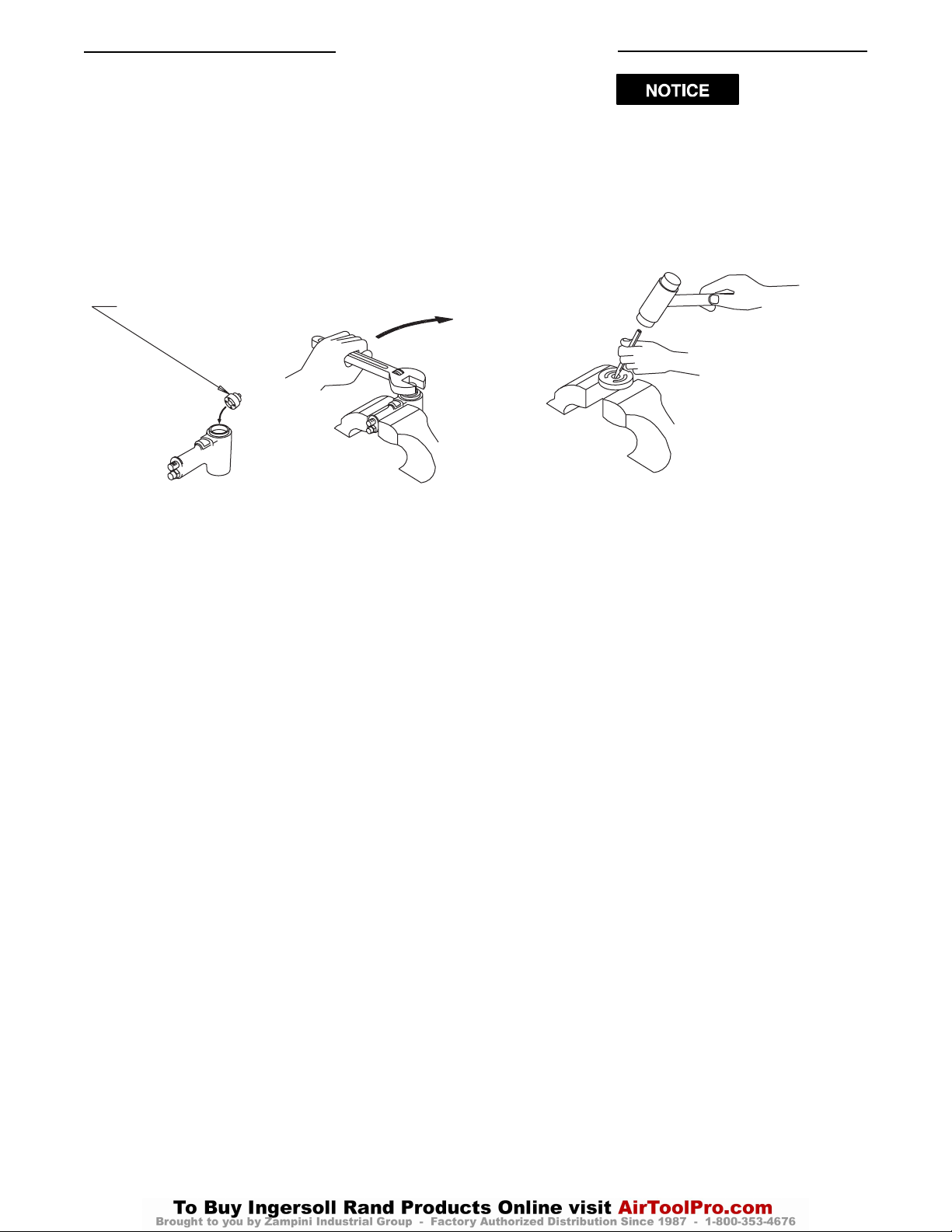
38
Maintenance Section (Continued)
Disassembly of the Motor
For Models
40PSQ1, 45PS3, 45PSQ1, 55PS3 and
55PSQ1:
1. Grasp the Motor Housing in vise jaws with the shaft of
the Rotor (30) upward.
2. Insert the pins of the end plate spacer spanner into the
holes in the Front End Plate Spacer (34). Using a
wrench, unscrew and remove the Spacer. This is a left-
handed thread; rotate the wrench clockwise to
remove the Spacer. (Refer to Dwg. TPD1269.)
(Dwg. TPD1269)
3. Position Motor Housing so that the Rotor Shaft is
facing downward. Tap the Cover Assembly (50) and
Motor Housing with a rubber mallet until the Cylinder
Assembly comes out.
NOTE: A rod (35) may slide out of the Rotor Shaft upon
removal, along with 3 Balls (41) inside the shutoff
mechanism.
4. Remove the motor from the vise jaws and remove the
Cylinder (27) and Vanes (29) from the Rotor (30).
For Models 70PS3 and 90PS4:
1. Grasp the Motor Housing (1) in vise jaws with the
Cover Assembly upward.
2. Using a hex wrench, remove the four Cover Assembly
Screws (53) and Lock Washers (54).
3. Lifting straight upward, remove the Cover Assembly
and assembled shut-off mechanism from the Motor
Housing and also the Gasket (55). Set the assembled
Cover Assembly aside.
4. Remove the Housing from the vise jaws and insert a
rod into the central opening in the output end of the
rotor shaft.
5. While holding the motor end of the Housing above a
piece of cardboard on the workbench, lightly tap the
rod to remove the Rear End Plate (26), Cylinder (27),
Front End Plate (31), Rotor and Vanes.
6. On the table of an arbor press, support the Rear End
Plate with blocks as close to the Rotor as possible and
press the Rotor out of the Bearing (1D).
In the following two steps, do not enlarge or damage the
shaft hole in the End Plate.
7. To remove the Front and Rear Rotor Bearing from the
Front and Rear End Plates, use a small drift or pin
punch through the central opening of the Rear End
Plate to tap the Bearing out of the End Plate. (Refer to
Dwg. TPD1271.)
(Dwg. TPD1271)
For All Models:
8. Using a Pin Punch, tap the Throttle Retaining Pin
(2) out of the Handle (1). The ends of the pin are
covered with cement.
9. Grasp the Throttle Knob (20) and pull the assembled
throttle and reverse valve out of the Motor Housing.
Take care not to loosen Spring (9).
10. Using a pin punch and without damaging the Throttle
Knob, remove the Pin (21).
11. Grasp the Reverse Lever (19) and pull the Reverse
Valve (23) from the front of the Throttle Bushing
Assembly. The Reverse Lever Detent Ball (18) and
Reverse Lever Detent Spring (17) will fall out of the
Reverse Valve. Take care not to lose them.
12. Remove the Throttle Rod Assembly from the rear of
the Throttle Bushing (16).
13. Remove the Throttle Rod Seal (10) from the Throttle
Rod (11).
14 If it is necessary to replace the Reverse Lever or
Reverse Valve, use a pin punch to tap out the Pin (22)
out of the Reverse Lever. Separate the Reverse Lever
from the Reverse Valve.
15. Using an adjustable wrench, unscrew and remove the
Hose Joint Assembly (8) and Exhaust Cover (6).
16. To disassemble the shut-off mechanism, grasp the
Cover Assembly in copper-covered vise jaws with the
Control Shaft Assembly upward.
17. Using a spanner wrench, unscrew the Control Bushing
Assembly and carefully separate the components. Be
doubly careful not to lose the three Control Bushing
Balls (41) from the shaft of the Control Bushing (34).
END PLATE
SPACER SPANNER
CLOCKWISE
TO LOOSEN
Page 39
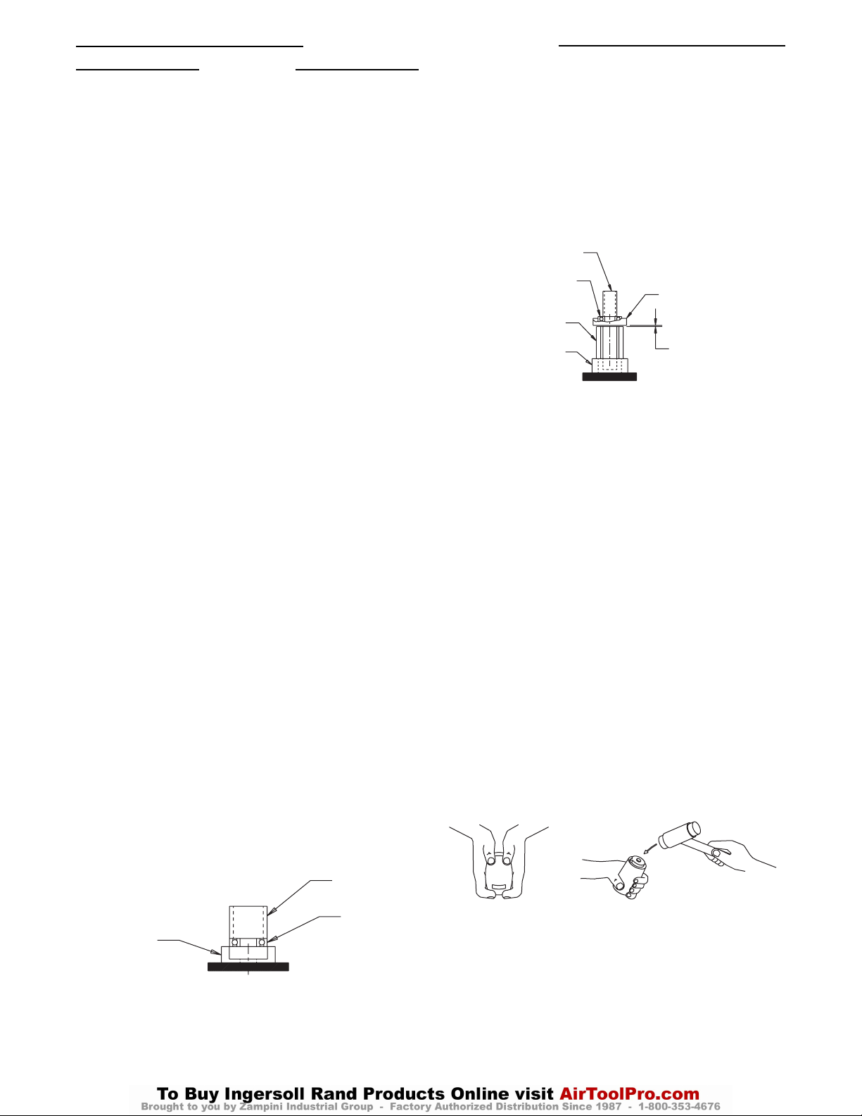
39
Maintenance Section (Continued)
Assembly
General Instructions
1. When grasping a tool or part in a vise, always use
leather-covered or copper-covered vise jaws to protect
the surface of the part and help prevent distortion. This
is particularly true of threaded members and housings.
2. Always press on the inner ring of a ball-type bearing
when installing the bearing on a shaft.
3. Always press on the outer ring of a ball-type bearing
when pressing the bearing into a bearing recess.
4. Except for bearings and mechanism parts, always clean
every part and wipe every part with a thin film of oil
before installation.
5. Wipe a thin film of mechanism fluid on all internal
mechanism components before installing them in the
mechanism.
6. Apply a film of O-Ring lubricant to every O-Ring
before installation.
Assembly of Motor:
1. If the Cover Assembly was disassembled, proceed with
the following. Otherwise go to Step 8.
2. Place seal (36) on the control shaft (37). Place the
spring (38) on the control shaft with grease, and insert
it into the control bushing (39) with the O-Ring end
trailing.
3. Apply grease to the ball holes in the control bushing,
insert three balls (41) into the control bushing OD.
4. Install adjusting bolt (42) into the small end of the
control bushing. The adjusting bolt should be tightened
to a depth of 3 mm below the surface.
5. Install the O-Ring (47) on the control valve (48).
Install both metal seals (44) onto the smaller end of the
control plate (45), then place the control plate onto the
control bushing, seals forward.
6. Install Spring (46) and the Control Valve Assembly
(with seal end leading) over the shaft of the Control
Bushing. Install the Control Bushing Seal (40) in the
annular groove located around the bushing shaft.
7. Fit Spring (49) against the Control Valve and thread
the entire assembly, with spring end leading, into the
Cover (50). While holding the Cover in the vise,
tighten the Control Bushing using a spanner wrench.
8. Using an arbor press and a piece of tubing that
contacts the outer ring of the bearings, press the Front
Rotor Bearing (33) into the Front End Plate (31) and
the Rear Rotor Bearing (25) into the Rear End Plate
(26). (Refer to Dwg. TPD1274.)
(Dwg. TPD1274)
9. Stand the Rotor on the table of an arbor press. It
should be upright on a flat metal plate having a
clearance hole for the shaft. The shaft with the hex
must be upward.
10. Place a 0.001" (0.025 mm) shim on the upward surface
of the large portion of the rotor body. Using a piece of
tubing that contacts the inner ring of the bearing, press
the Front Rotor Bearing and Front End Plate (with end
plate leading) onto the shaft of the Rotor until the End
Plate contacts the shim. Remove the shim. (Refer to
Dwg. TPD1275.)
(Dwg. TPD1275)
11. Coat each Vane with a thin film of oil and insert a
Vane into each of the rotor vane slots with the straight
edge of the Vane outward.
12. Install the Cylinder over the Vanes and Rotor making
certain the End Plate Alignment Dowel (28) enters the
notch in the face of the end plate.
13. Stand the assembly on an arbor press table so that the
rotor shaft on the front end plate end contacts the table.
Using a tube that contacts both inner and outer faces of
the Rear Rotor Bearing, press the Rear End Plate
Assembly, bearing end trailing, into the Rotor shaft
against the Cylinder.
14. Insert both O-Rings (24) into the internal grooves
inside the Housing Motor Bore.
❑ Continue here for Models 40PSQ1, 45PS3,
45PSQ1, 55PS3 and 55PSQ1
➢ Go to Step 19 for Models 70PS3 and 90PS4
15. Install the gasket and cover assembly, securing with
screws and Lock Washers. Tighten each screw between
30-35 lb-in. (3.4-4.0 Nm).
16. Insert the motor assembly into the Motor Housing. It
may be necessary to tap the assembly into position with
a brass or plastic hammer. (Refer to Dwg. TPD1279.)
(Dwg. TPD1279)
PRESSING PLUG
FRONT ROTOR
BEARING
ROTOR
PLATE WITH ROTOR
SHAFT CLEARANCE
FRONT END PLATE
0.001" (0.025 mm)
SHIM SPACE
END PLATE
TUBING
BEARING
Page 40
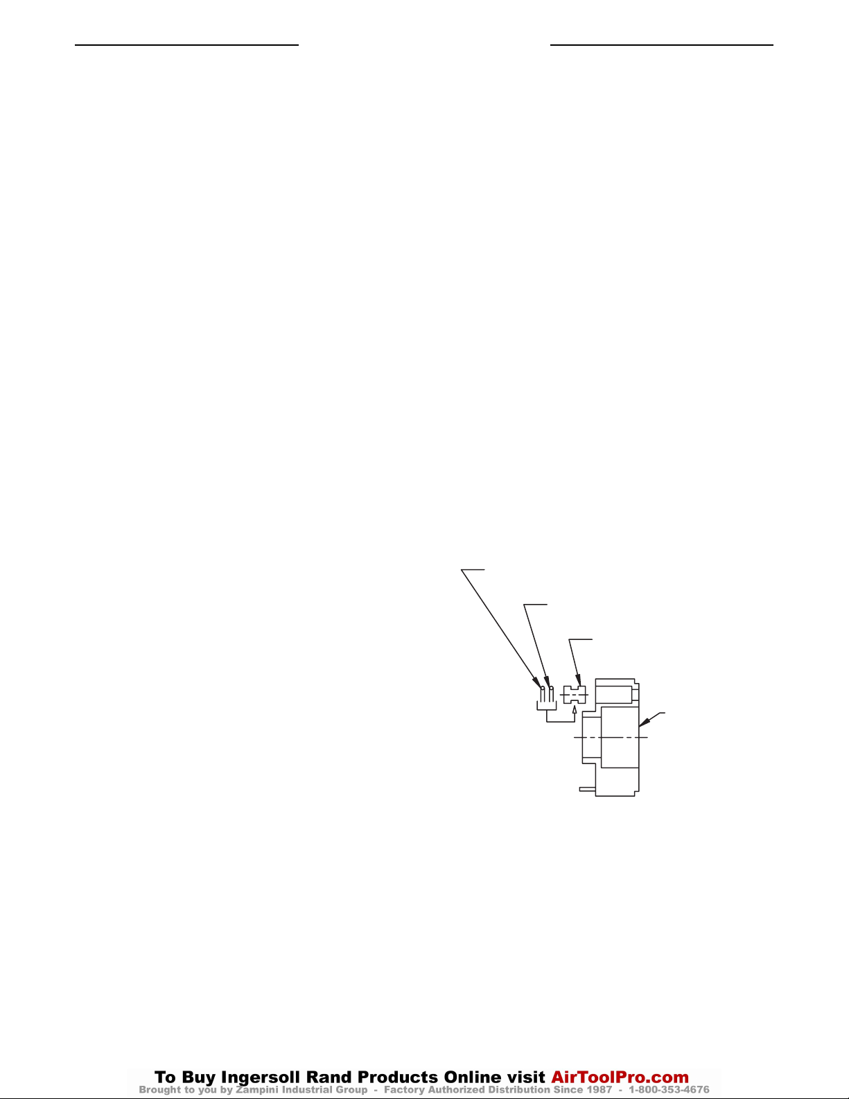
40
Maintenance Section (Continued)
17. Grasp the handle of the Motor Housing in vise jaws
with the rotor shaft upward. Thread the Front End
Plate Spacer (34) into the Housing and using the end
plate spacer spanner, tighten the Spacer to 27 ft-lb (38
Nm) torque. This is a left-handed thread; rotate the
wrench counterclockwise to tighten.
18. After installing the Front End Plate Spacer, grasp the
shaft of the Rotor and rotate it by hand. If the Rotor
does not turn easily, disassemble the motor unit and
determine where the assembly is binding. The motor
must rotate freely before proceeding further with the
assembly. Now install the Silencer (5) into the Exhaust
Cover (6) followed by O-Ring (4).
❑ Go to Step 22 for Models 40PSQ1, 45PS3,
45PSQ1, 55PS3 and 55PSQ1
➢ (From Step 14): Go to Step 19 for Models
70PS3 and 90PS4
19. For Models 70PS3 and 90PS4, insert the Motor
Assembly into the Motor Housing. It may be necessary
to tap the assembly into position with a brass or plastic
hammer.
20. Secure the Cover to the Housing by installing the
Screws (53) and Lock Washers (54). Tighten each
Screw between 45 and 50 in-lb (5.1 and 5.6 Nm)
torque.
21. Install Silencer (5) into the Exhaust Cover, followed by
Screen (J) and O-Ring (4).
22. Install O-Ring (7) onto the Hose Joint Assembly,
followed by the Exhaust Cover Assembly.
23. Coat the Hose Joint Assembly thread with thread lock
and secure it to the Housing.
24. Install the Throttle Rod Seal in the groove on the large
hub of the Throttle Rod.
25. Install the Throttle Valve Seal in the groove on the
large hub of the Throttle Valve.
26. Slide the Throttle Valve, Valve Seal end first, onto the
Throttle Valve Rod.
27. Secure the Throttle Valve Assembly by installing the
Valve Retaining Ring in the small groove on the
Throttle Valve Rod.
28. Insert the Reverse Valve part way into the Throttle
Bushing. Install the Spring and Detent Ball, then
carefully push the Reverse Valve the rest of the way
into the Throttle Bushing.
29. Insure that the Detent Ball is aligned with one of the
holes in the side of the Throttle Bushing.
30. Install the O-Ring in the groove on the Throttle
Bushing.
31. Assemble the Reverse Lever onto the Reverse Valve
and secure with a Roll Pin.
32. Insert the Throttle Valve Assembly through the Reverse
Valve, then secure with the Throttle Knob and a Roll
Pin.
33. Insert the Trigger and Reverse Valve Assembly into the
Motor Housing, taking care to align the slots in the
Reverse Valve and Throttle Bushing with the pin hole
in the Motor Housing.
34. Secure Trigger and Reverse Valve Assembly with pin,
which should be centered from side to side.
35. To prevent air leakage, after pin assembly seal each
end of the pin with cement.
Assembly of Impulse Mechanism
1. Install O-Ring (72) onto Spring Guide (71) using the
O-Ring Installer from IR Repair Kit. Model 45PS-99
use kit 180PQ-99; Model 90PS4 use kit 90PS-99.
Install O-Rings 69 (or 69 and K) onto Check Valve
(68) using the same O-Ring installer.
2. When looking inside the central opening of the Liner
(64), the internal wall has three holes on one side
which do not extend through the wall. The opening on
the end face of that wall is for the Relief Valve (70).
Install the Relief Valve and Spring Guide Assembly
into this hole.
3. Insert the Spring (65), Spring Guide (66) (with the
large end trailing), the Check Valve Ball (67) and
Check Valve Assembly into the hole on the opposite
wall of the Liner.
4. Install the Backup Ring (60) and O-Ring (61) onto the
Sensor (59), using the O-Ring Installer.
5. Insert the assembly (with Seal end leading) into the
central opening of the Cover (57). Make certain the
assembly slides freely in the opening.
❑ Continue here for Models 40PSQ1, 45PS3,
45PSQ1, 55PS3 and 55PSQ1
➢ Go to Step 20 for Model 90PS4 (only)
6. Install the O-Ring (79) and Backup Ring (81) onto the
Oil Stop Cap (80). Insert the Oil Stop Cap Assembly
into the hole opposite the locating pin, on the front
face of the Front Liner Cover (82).
7. Insert the Backup Ring (77), chamfer first, into the
internal face of the Front Cover.
(Dwg. TPD1287)
8. Insert the O-Ring (76) over the output end of the Drive
Shaft.
9. Insert a Blade into one slot in the Drive Shaft. Install
the Blade Springs (74) through the Drive Shaft and
into the holes in the blade. Place the remaining Blade
on the Springs, making certain the Springs enter the
holes in the blade.
10. Using finger pressure, compress the Springs with the
Blades until the outer edges of the Blades are flush
with the Drive Shaft surface. Capture the Blades in this
position by inserting into the Liner Assembly.
BACK-UP RING
STOP CAP O-RING
OIL STOP CAP
FRONT LINER
COVER
Page 41

41
Maintenance Section (Continued)
11. Prior to installing the O-Ring (62), assemble the rear
Cover onto the Drive Shaft, oriented by the locating
pins. Make sure the 3rd Hole in the face lines up with
the 3rd Hole in the Liner.
12. Viewed from the front of the Impulse Mechanism, with
the Relief Valve’s 3 internal holes oriented above the
Check Valve’s single internal hole below; the Liner
Case (91) is correctly oriented when the Oil Plug
recess is to the left of center.
13. Lightly coat O-Rings (62, 78) with a suitable lubricant
and install them over the covers into the grooves
provided. The larger cross-section O-Ring goes in the
groove to the rear of the mechanism.
14. Install the 1st Rubber Plate (88), Spring (89), 2nd
Rubber plate and Screw (87) in each hole in the side of
the Liner Case.
15. Install both Adjustment Screws (90) into the Liner
Case, inserting them from the internal side. The Screws
are adjusted from the external end of the Liner Case,
with the Wrench extending through the Liner Case.
16. Install the O-Ring (86) into the internal groove of the
Liner Case. Apply a light coat of grease to the
O-Rings.
17. Place the Liner Case over the assembled Liner. Make
sure the notch in the face of the Liner Case aligns with
the Oil Plug hole. Using the Pressing Sleeve from the
Tool Kit, carefully press the Liner Case into position.
Do not damage O-Rings during installation.
18. Grasp the flats on the Liner Housing in a vise. Using
the Spanner Plug furnished with the Tool Kit, install
the Liner Cap (56). This is a left-handed thread.
19. Tighten the Housing Cap to 8-10 Nm for 40PSQ1,
45PS3, 45PSQ1, 55PS3 and 55PSQ1 Series; and 12-14
Nm for the 70PS3.
20. Make sure the Drive Shaft rotates freely, then fill the
Impulse Mechanism with fluid, as instructed in the
section, Changing the Mechanism Fluid.
❑ The “Assembly” process is now complete for
Models 40PSQ1, 45PS3, 45PSQ1, 55PS3 and
55PSQ1.
➢ Continued here (from Step 5) for Model 90PS4.
21. Install the two Bushings (P) and the two Nylon
Bushings (Q) and pin (83) in the front face of the Front
Liner Cover (82). Install both Adjustment Screws (90)
into the Front Liner Cover (82), inserting them from
the internal side. The Screws are adjusted from the
external end of the Cover, with the Wrench extending
through the Cover.
22. Install the O-Ring (62) in the annular groove on the
face of the Rear Liner Cover (57).
23. Install the O-Rings (M) in the openings on the face of
the Front Liner Cover.
24. Install the Seal Back-Up Ring (77) followed by the
Drive Shaft O-Ring (76) in the central opening in the
face of the Front Liner Cover.
25. Insert the short round hub of the Drive Shaft into the
central opening of the Rear Liner Cover.
26. Insert a Blade (73) into one slot in the Drive Shaft.
Install the Blade Springs (74) through the Drive Shaft
and into the holes in that Blade. Place the remaining
Blade on the Springs making certain the Springs enter
the holes in that Blade.
27. Using finger pressure, compress the Springs with the
Blades until the outer edges of the Blades are flush
with the drive shaft surface. Capture the Blades in this
position by installing the Liner Assembly, piston stop
end trailing, over the Drive Shaft and against the Rear
Liner Cover.
28. Install the Front Cover Assembly over the Drive Shaft
and against the Liner. Viewed from the front of the
Impulse Mechanism, with the Relief Valve’s 3 internal
holes oriented above the Check Valve’s single internal
hole below; the Front Case is correctly oriented when
the Oil Plug recess is to the left of center.
29. Install the two Liner Cover Seals (86) in the grooves
inside the Liner Case (91) near the end with the
external wrench flats.
30. Place the Liner Case (with Seal end trailing) over the
assembled Liner. Make certain the notch in the trailing
end face of the Case aligns with the Oil Plug (85) in
the Front Liner Cover. Use the Pressing Sleeve from
the Tool Kit to press the Case over the Seals and into
position. Do not damage the Seals during installation.
31. Grasp the flats of the Liner Case in vise jaws and using
the Spanner Plug furnished with the Tool Kit and a
torque wrench, install the Housing Cap. This is a left-
handed thread; rotate the wrench counterclockwise
to tighten the Cap. Tighten the Cap 81-21 Nm of
torque.
32. Make certain the Drive Shaft rotates freely and then
fill the mechanism with fluid and reassemble the tool
as instructed in the section, Changing the Mechanism
Fluid.
Page 42
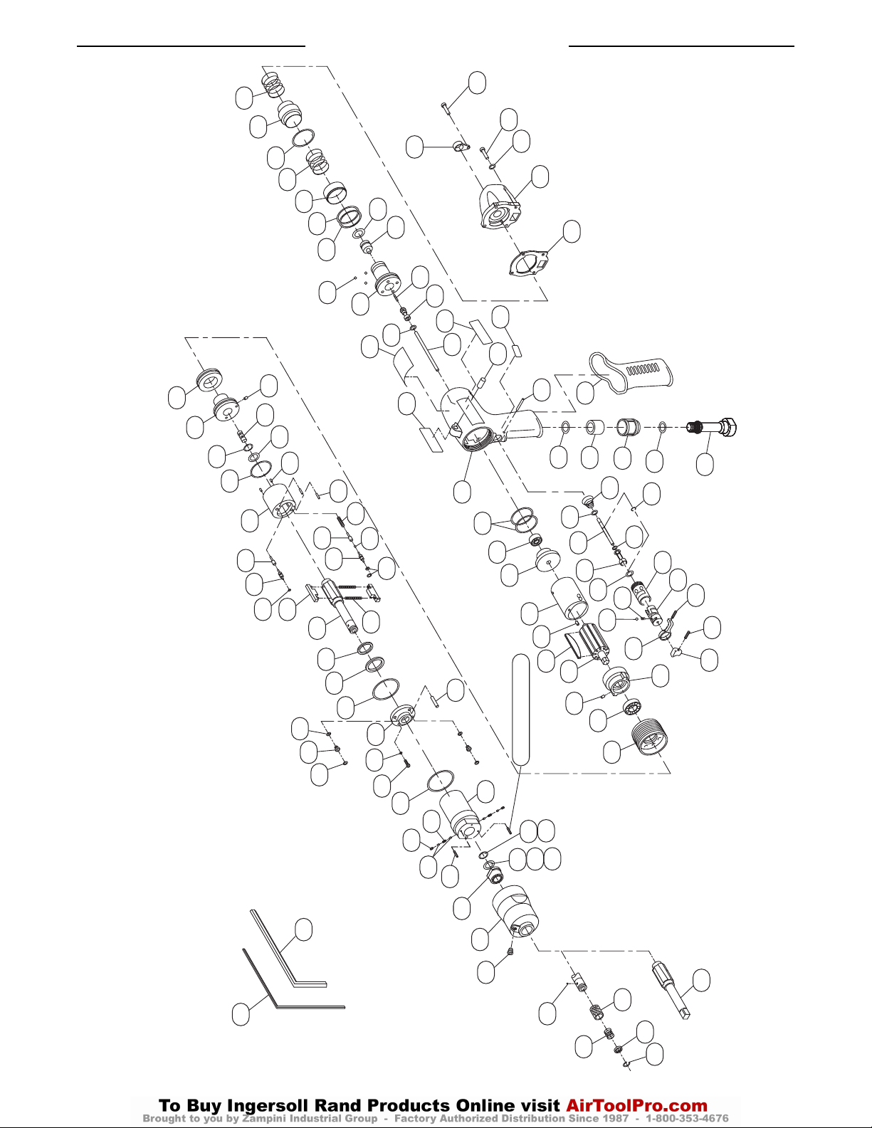
42
Maintenance Section (Continued)
Models 40PSQ1, 45PS3, 45PSQ1, 55PS3 and 55PSQ1
(Dwg. TPA1730-1)
F
E
104
103
102
101
100
99
98
97
90
88
87
89
94
95
96
92
93
91
86
85
84
82
83
81
80
79
78
77
76
105
74
73
72
71
70
64
63
69
68
67
66
65
63
62
61
60
59
57
58
56
49
48
47
46
45
44
43
40
42
41
39
38
37
36
G
35
B
3
A
2
C
1
24
25
26
27
28
29
30
32
31
33
34
20
21
22
19
18
17
23
16
15
14
13
11
10
9
12
4
5
6
7
8
D
55
50
54
53
52
51
75
Identified with yellow paint
Page 43
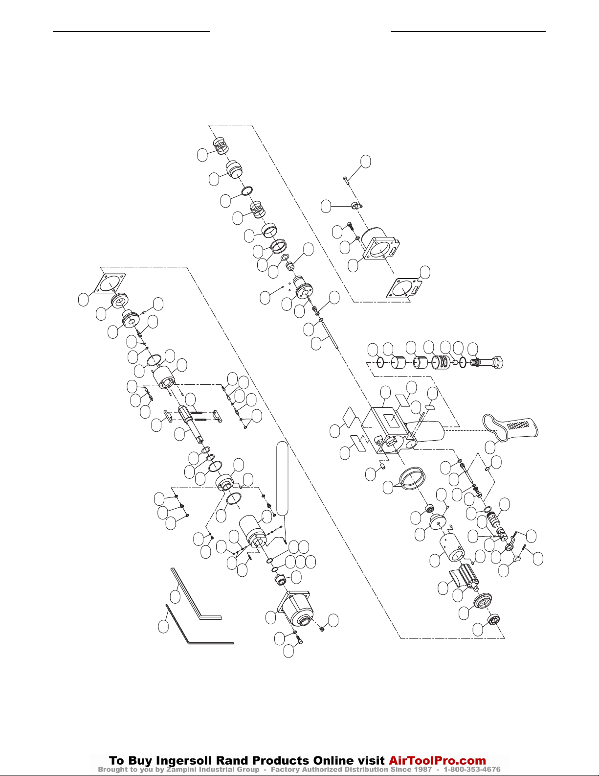
43
Maintenance Section (Continued)
(Dwg. TPA1732-1)
Model 70PS3
108
56
57
49
48
47
46
45
44
43
40
58
59
60
61
62
70
72
63
64
65
74
71
73
75
76
77
78
79
80
81
E
86
84
89
87
85
88
41
39
66
67
68
69
82
83
Identified with yellow paint
91
92
90
94
51
42
37
38
36
35
G
93
96
95
97
52
53
54
50
J
4
1
C
3
24
55
6
5
B
2
25
26
7
H
8
A
D
10
11
32
13
27
29
30
12
14
15
18
16
17
23
28
19
22
21
20
F
98
106
107
99
31
33
Page 44
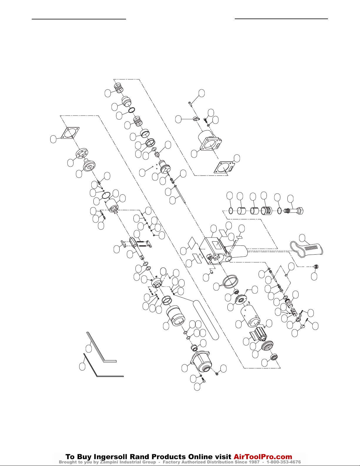
Maintenance Section (Continued)
Model 90PS4
(Dwg. TPA1733-1)
44
108
56
49
48
47
46
45
44
43
40
57
E
F
59
60
61
62
70
72
63
64
71
73
41
39
65
66
68
67
69
74
75
76
77
M
L
84
85
86
51
42
37
38
36
35
K
G
82
8
83
P
Q
R
91
52
53
54
50
1
C
3
24
93
92
94
95
Identified with yellow paint
97
98
55
4
J
B
A
2
25
26
27
99
6
5
32
29
30
31
7
8
D
12
10
11
13
14
15
18
28
33
16
17
23
19
20
N
22
21
106
107
Page 45

Maintenance Section (Continued)
Parts List
Operations Maintenance Manual (P7528) — Impulse Wrench
When ordering use applicable Model Part Numbers
Item Part Description Model Model Model Model Model Model Model
40PSQ1 45PS3 45PSQ1 55PS3 55PSQ1 70PS3 90PS4
--- Housing Assembly 40PSQ1-A40 55PS3-A40 55PS3-A40 55PS3-A40 55PS3-A40 70PS3-A40 90PS4-A40
1 Housing --- --- --- --- --- --- ---
G Warning Label WARNING-27-99 WARNING-27-99 WARNING-27-99 WARNING-27-99 WARNING-27-99 WARNING-27-99 WARNING-27-99
2 Pin 45PS3-297 45PS3-297 45PS3-297 45PS3-297 45PS3-297 100PQ-297 100PQ-297
3 Pin 70P3-232 70P3-232 70P3-232 70P3-232 70P3-232 70P3-232 70P3-232
S Exhaust Bushing 40PSQ1-233 40PSQ1-233 N/A N/A N/A N/A N/A
4 O-Ring 100PQ-236 100PQ-236 100PQ-236 100PQ-236 100PQ-236 100PQ-236 100PQ-236
5 Silencer 45P3-506 45P3-506 45P3-506 45P3-506 45P3-506 70P3-505 70P3-505
J Silencer N/A N/A N/A N/A N/A 70P3-506 70P3-506
6 Exhaust Cover 45P3-978 45P3-978 45P3-978 45P3-978 45P3-978 70P3-978 70P3-978
H Socket Plug N/A N/A N/A N/A N/A 70PS3-34 N/A
7 Seal EQ106P-283 EQ106P-283 EQ106P-283 EQ106P-283 EQ106P-283 EQ106P-283 EQ106P-283
8 Hose Joint Assembly 45PS3-A979 45PS3-A979 45PS3-A979 45PS3-A979 45PS3-A979 70PS3-A979 70PS3-A979
9 Spring 45PS3-52 45PS3-52 45PS3-52 45PS3-52 45PS3-52 N/A N/A
N Oil Plug N/A N/A N/A N/A N/A N/A 90P4-221
--- Throttle Rod Assembly EQ112P-A302 EQ112P-A302 EQ112P-A302 EQ112P-A302 EQ112P-A302 70PS3-A302 70PS3-A302
10 O-Ring EQ106S-288 EQ106S-288 EQ106S-288 EQ106S-288 EQ106S-288 EQ106S-288 EQ106S-288
11 Throttle Rod --- --- --- --- --- --- ---
12 Snap Ring EQ106P-303 EQ106P-303 EQ106P-303 EQ106P-303 EQ106P-303 EQ106P-303 EQ106P-303
--- Throttle Rod Bushing Assy. 40PSQ1-A303 40PSQ1-A303 40PSQ1-A303 40PSQ1-A303 40PSQ1-A303 70PS3-A503 70PS3-A503
13 O-Ring 100PQ-288 100PQ-288 100PQ-288 100PQ-288 100PQ-288 70PS3-270 70PS3-270
14 Throttle Rod Bushing --- --- --- --- --- --- ---
--- Throttle Bushing Assembly 55P3-A503 55P3-A503 55P3-A503 55P3-A503 55P3-A503 70P3-A503 70P3-A503
15 Seal EQ106P-283 EQ106P-283 EQ106P-283 EQ106P-283 EQ106P-283 55P3-303 55P3-303
16 Throttle Bushing --- --- --- --- --- --- ---
17 Spring 100PQ-568 100PQ-568 100PQ-568 100PQ-568 100PQ-568 100PQ-568 100PQ-568
18 Ball EQ104S-929 EQ104S-929 EQ104S-929 EQ104S-929 EQ104S-929 EQ104S-929 EQ104S-929
19 Reverse Lever 45PS3-328 45PS3-328 45PS3-328 45PS3-328 45PS3-328 100PQ-328 100PQ-328
20 Throttle Knob EQ106P-93 EQ106P-93 EQ106P-93 EQ106P-93 EQ106P-93 70P3-328 70P3-328
21 Pin EQ106P-265 EQ106P-265 EQ106P-265 EQ106P-265 EQ106P-265 EQ106P-265 EQ106P-265
22 Roll Pin 180SQ-152 180SQ-152 180SQ-152 180SQ-152 180SQ-152 180SQ-152 180SQ-152
23 Reverse Valve 55PS3-329 55PS3-329 55PS3-329 55PS3-329 55PS3-329 70PS3-329 70PS3-329
24 O-Ring (qty 2) 45P3-223 55P3-223 55P3-223 55P3-223 55P3-223 70P3-236 90P4-236
D Grip 55P3-2 55P3-2 55P3-2 55P3-2 55P3-2 70P3-2 70P3-2
--- Rear End Plate Assembly 40PSQ1-A12 45PS3-A12 45PS3-A12 55PS3-A12 55PS3-A12 70PS3-A12 90PS4-A12
45
Page 46

Maintenance Section (Continued)
Parts List
Operations Maintenance Manual (P7528) — Impulse Wrench
When ordering use applicable Model Part Numbers
Item Part Description Model Model Model Model Model Model Model
40PSQ1 45PS3 45PSQ1 55PS3 55PSQ1 70PS3 90PS4
25 Bearing 40PSQ1-22 45PS3-22 45PS3-22 45PS3-22 45PS3-22 70PS3-22 70PS3-22
26 Rear End Plate 45P3-12 45PS3-12 45PS3-12 55PS3-12 55PS3-12 70PS3-12 90PS4-12
--- Cylinder Assembly 40PSQ1-A3 45PS3-A3 45PS3-A3 55PS3-A3 55PS3-A3 70PS3-A3 90P4-A3
27 Cylinder --- --- --- --- --- --- ---
28 Pin (qty 2) 45P3-297 380SQ-298 380SQ-298 380SQ-298 380SQ-298 380SQ-298 380SQ-298
29 Vane Pack 40PSQ1-42-9 45PS3-42-9 45PS3-42-9 55P3-42-9 55P3-42-9 70P3-42-9 90P4-42-9
30 Rotor 40PSQ1-53 45PS3-53 45PS3-53 55PS3-53 55PS3-53 70PS3-53 90PS4-53
--- Front End Plate Assembly 40PSQ1-A11 55PS3-A11 55PS3-A11 55PS3-A11 55PS3-A11 70PS3-A11 90PS4-A11
31 Front End Plate 40PSQ1-11 55PS3-11 55PS3-11 55PS3-11 55PS3-11 70PS3-11 90PS4-11
32 Pin (qty 2) 45P3-297 380SQ-298 380SQ-298 380SQ-298 380SQ-298 70P3-297 70P3-297
33 Ball Bearing 55PS3-105 55PS3-105 55PS3-105 55PS3-105 55PS3-105 55PS3-105 90PS4-22
34 Spacer 40PSQ1-10 55P3-10 55P3-10 55P3-10 55P3-10 N/A N/A
35 Rod 40PSQ1-900 55PS3-900 55PS3-900 55PS3-900 55PS3-900 70PS3-900 90PS4-900
--- Cover Assembly 40PSQ1-A202 55PS3-A202 55PS3-A202 55PS3-A202 55PS3-A202 70PS3-A202 90PS4-A202
--- Control Shaft Assembly 55PS3-A69 55PS3-A69 55PS3-A69 55PS3-A69 55PS3-A69 70PS3-A69 70PS3-A69
36 Seal EQ110P-288 EQ110P-288 EQ110P-288 EQ110P-288 EQ110P-288 EQ110P-288 EQ110P-288
37 Control Shaft 55PS3-69 55PS3-69 55PS3-69 55PS3-69 55PS3-69 70PS3-69 70PS3-69
38 Spring 45PS3-51 45PS3-51 45PS3-51 45PS3-51 45PS3-51 90PS4-51 90PS4-51
--- Control Bushing Assembly 55PS3-A333 55PS3-A333 55PS3-A333 55PS3-A333 55PS3-A333 70PS3-A333 70PS3-A333
39 Control Bushing 55PS3-333 55PS3-333 55PS3-333 55PS3-333 55PS3-333 70PS3-333 70PS3-333
40 O-Ring 180PQ-288 180PQ-288 180PQ-288 180PQ-288 180PQ-288 180PQ-288 180PQ-288
41 Balls (qty 3) 04351904 04351904 04351904 04351904 04351904 04351904 04351904
42 Bolt 55PS3-683 55PS3-683 55PS3-683 55PS3-683 55PS3-683 55PS3-683 55PS3-683
43 Seal 45PS3-773 45PS3-773 45PS3-773 45PS3-773 45PS3-773 70PS3-773 70PS3-773
44 Seal 45PS3-774 45PS3-774 45PS3-774 45PS3-774 45PS3-774 70PS3-774 70PS3-774
45 Control Plate 55PS3-485 55PS3-485 55PS3-485 55PS3-485 55PS3-485 70PS3-485 70PS3-485
46 Spring 45PS3-152 45PS3-152 45PS3-152 45PS3-152 45PS3-152 04351847 04351847
--- Control Valve Assembly 55PS3-A526 55PS3-A526 55PS3-A526 55PS3-A526 55PS3-A526 70PS3-A526 70PS3-A526
47 O-Ring 90P4-272 90P4-272 90P4-272 90P4-272 90P4-272 04351870 04351870
48 Control Valve 55PS3-526 55PS3-526 55PS3-526 55PS3-526 55PS3-526 70PS3-526 70PS3-526
49 Spring 45PS3-151 45PS3-151 45PS3-151 45PS3-151 45PS3-151 04351839 04351839
50 Cover 40PSQ1-202 55PS3-202 55PS3-202 55PS3-202 55PS3-202 70PS3-202 90PS4-202
51 Cover 45PS3-144 45PS3-144 45PS3-144 45PS3-144 45PS3-144 45PS3-144 45PS3-144
52 Screw 45PS3-170 45PS3-170 45PS3-170 45PS3-170 45PS3-170 45PS3-170 45PS3-170
46
Page 47

47
Maintenance Section (Continued)
Parts List
Operations Maintenance Manual (P7528) — Impulse Wrench
When ordering use applicable Model Part Numbers
Item Part Description Model Model Model Model Model Model Model
40PSQ1 45PS3 45PSQ1 55PS3 55PSQ1 70PS3 90PS4
53 Screw (qty 4) 700P-638 45PS3-638 45PS3-638 45PS3-638 45PS3-638 04351946 04351946
54 Washer (qty 4) 500P-58 45PS3-248 45PS3-248 45PS3-248 45PS3-248 900P-58 900P-58
55 Gasket 45P3-739 55PS3-739 55PS3-739 55PS3-739 55PS3-739 70PS3-739 90PS4-739
56 Liner Cap 40PSQ1-207 180PQ-207 180PQ-207 180PQ-207 180PQ-207 380PQ-207 90PS4-207
57 Cover 40PSQ1-212 55PS3-212 55PS3-212 55PS3-212 55PS3-212 70PS3-212 90PS4-212
58 Screw 45PS3-55 45PS3-55 45PS3-55 45PS3-55 45PS3-55 45PS3-55 N/A
--- Sensor Assembly 55PS3-A101 55PS3-A101 55PS3-A101 55PS3-A101 55PS3-A101 55PS3-A101 55PS3-A101
59 Sensor 55PS3-101 55PS3-101 55PS3-101 55PS3-101 55PS3-101 55PS3-101 55PS3-101
60 Backup O-Ring 45PS3-728 45PS3-728 45PS3-728 45PS3-728 45PS3-728 45PS3-728 45PS3-728
61 O-Ring 45PS3-75 45PS3-75 45PS3-75 45PS3-75 45PS3-75 45PS3-75 45PS3-75
62 O-Ring 45P3-273 180PQ-273 180PQ-273 180PQ-273 180PQ-273 EQ106S-236 90P4-237
--- Liner Assembly 40PSQ1-A203 55PS3-A203 55PS3-A203 55PS3-A203 55PS3-A203 70PS3-A203 90P4-A203
63 Pin (qty 4) 180PQ-298 180PQ-298 180PQ-298 180PQ-298 180PQ-298 70P3-298 90P4-297
64 Liner --- --- --- --- --- --- ---
65 Spring 40PSQ1-260 45PS3-260 45PS3-260 45PS3-260 45PS3-260 70PS3-260 90PS4-260
66 Spring Guide 55PS3-355 55PS3-355 55PS3-355 55PS3-355 55PS3-355 70PS3-355 90PS4-355
67 Ball 40PSQ1-333 40PSQ1-333 40PSQ1-333 40PSQ1-333 40PSQ1-333 40PSQ1-333 500P-333
--- Check Valve Assembly 40PSQ1-A265 55PS3-A265 55PS3-A265 55PS3-A265 55PS3-A265 55PS3-A265 90PS4-A265
68 Check Valve 40PSQ1-265 55PS3-265 55PS3-265 55PS3-265 55PS3-265 55PS3-265 90PS4-265
69 O-Ring (qty 2) 180PQ-272 180PQ-272 180PQ-272 180PQ-272 180PQ-272 180PQ-272 180PQ-272
K O-Ring N/A N/A N/A N/A N/A N/A EQ106S-288
70 Relief Valve 180PQ-222 180PQ-222 180PQ-222 180PQ-222 180PQ-222 380PQ-222 90P4-222
--- Spring Guide Assembly 40PSQ1-A255 180PQ-A255 180PQ-A255 180PQ-A255 180PQ-A255 70PS3-A255 EQ208S-A255
71 Spring Guide --- --- --- --- --- --- ---
72 O-Ring (qty 2) 180PQ-272 180PQ-272 180PQ-272 180PQ-272 180PQ-272 180PQ-272 EQ106S-288
--- Blade Assembly (qty 2) N/A 180PQ-A627 180PQ-A627 180PQ-A627 180PQ-A627 380PQ-A627 N/A
73 Blade (qty 2) 45P3-220 --- --- --- --- --- 90P4-220
74 Spring (qty 2) 45P3-568 180PQ-568 180PQ-568 180PQ-568 180PQ-568 380PQ-568 EQ212P-219
--- Shaft Assembly N/A 45PS3-A626 N/A 45PS3-A626 N/A 70PS3-A626 90PS4-A626
75 Shaft N/A --- N/A --- N/A --- ---
76 O-Ring 40PSQ1-271 55P3-271 55P3-271 55P3-271 55P3-271 55P3-271 90PS4-797
77 Backup O-Ring 40PSQ1-224 55P3-224 55P3-224 55P3-224 55P3-224 55P3-224 90P4-224
M O-Ring N/A N/A N/A N/A N/A N/A EQ208S-238
78 O-Ring N/A EQ104S-236 EQ104S-236 EQ104S-236 EQ104S-236 380PQ-288 N/A
Page 48

Maintenance Section (Continued)
Parts List
Operations Maintenance Manual (P7528) — Impulse Wrench
When ordering use applicable Model Part Numbers
Item Part Description Model Model Model Model Model Model Model
40PSQ1 45PS3 45PSQ1 55PS3 55PSQ1 70PS3 90PS4
--- Oil Stop Cap Assembly (qty 2) 180PQ-A38 180PQ-A38 180PQ-A38 180PQ-A38 180PQ-A38 180PQ-A38 N/A
79 Seal (qty 2) EQ106S-288 EQ106S-288 EQ106S-288 EQ106S-288 EQ106S-288 EQ106S-288 N/A
80 Oil Stop Cap (qty 2) --- --- --- --- --- --- N/A
81 Backup O-Ring (qty 2) 380SQ-272 380SQ-272 380SQ-272 380SQ-272 380SQ-272 380SQ-272 N/A
--- Front Liner Cover Assembly 40PSQ1-A211 55PS3-A211 55PS3-A211 55PS3-A211 55PS3-A211 70PS3-A211 90PS4-A211
82 Front Liner Cover --- --- --- --- --- --- ---
83 Pin 180PQ-232 180PQ-232 180PQ-232 180PQ-232 180PQ-232 180PQ-232 90P4-235
P Bushing (qty 2) N/A N/A N/A N/A N/A N/A 90PS4-649
Q Bushing (qty 2) N/A N/A N/A N/A N/A N/A 90PS4-641
R Screw (qty 2) N/A N/A N/A N/A N/A N/A 90P4-230
L Washer N/A N/A N/A N/A N/A N/A EQ106S-229
84 O-Ring EQ110P-288 EQ110P-288 EQ110P-288 EQ110P-288 EQ110P-288 EQ110P-288 EQ106S-228
85 Oil Plug 180PQ-277 180PQ-277 180PQ-277 180PQ-277 180PQ-277 180PQ-277 EQ106S-277
--- Liner Case Assembly 40PSQ1-A31 55PS3-A31 55PS3-A31 55PS3-A31 55PS3-A31 70PS3-A31 N/A
86 O-Ring 40PSQ1-236 180PQ-236 180PQ-236 180PQ-236 180PQ-236 EQ208S-237 EQ106S-36
87 Screw (qty 2) 40PSQ1-230 70P3-230 70P3-230 70P3-230 70P3-230 70P3-230 N/A
88 Rubber Plate (qty 4) 40PSQ1-225 60P3-283 60P3-283 60P3-283 60P3-283 60P3-283 N/A
89 Spring (qty 2) 180PQ-219 70P3-219 70P3-219 70P3-219 70P3-219 70P3-219 N/A
90 Screw (qty 2) 180PQ-230 180PQ-230 180PQ-230 180PQ-230 180PQ-230 180PQ-230 N/A
91 Liner Case --- --- --- --- --- --- 90PS4-31
92 Seal 40PSQ1-273 45PS3-271 45PS3-271 45PS3-271 45PS3-271 45PS3-271 04354932
93 Seal 40PSQ1-272 45PS3-272 45PS3-272 45PS3-272 45PS3-272 45PS3-272 04354940
94 Washer 40PSQ1-229 45PS3-229 45PS3-229 45PS3-229 45PS3-229 45PS3-229 90PS4-80
95 Washer 04351656 180PQ-229 180PQ-229 180PQ-229 180PQ-229 180PQ-229 90PS4-79
96 Bushing 40PSQ1-232 45P3-229 45P3-229 45P3-229 45P3-229 45P3-229 N/A
--- Hammer Case Assembly 40PSQ1-A727 60P3-A727 60P3-A727 60P3-A727 60P3-A727 70PS3-A727 90P4-A727
97 Main Shaft Bushing 40PSQ1-641 55P3-641 55P3-641 55P3-641 55P3-641 180PQ-641 90P4-641
98 Hammer Case 40PSQ1-727 60P3-727 60P3-727 60P3-727 60P3-727 70PS3-727 90P4-727
99 Socket Plug 40PSQ1-95 60P3-95 60P3-95 60P3-95 60P3-95 180PQ-95 180PQ-95
T Snap Ring 100PQ-303 N/A N/A N/A N/A N/A N/A
--- Bit Chuck Assembly 180PQ-A667 N/A 180PQ-A667 N/A 180PQ-A667 N/A N/A
100 Ball EQ104S-929 N/A EQ104S-929 N/A EQ104S-929 N/A N/A
101 Bit Sleeve EQ104S-930 N/A EQ104S-930 N/A EQ104S-930 N/A N/A
102 Spring EQ104S-931 N/A EQ104S-931 N/A EQ104S-931 N/A N/A
48
Page 49

Maintenance Section (Continued)
Parts List
Operations Maintenance Manual (P7528) — Impulse Wrench
When ordering use applicable Model Part Numbers
Item Part Description Model Model Model Model Model Model Model
40PSQ1 45PS3 45PSQ1 55PS3 55PSQ1 70PS3 90PS4
103 Spring Seat EQ104S-932 N/A EQ104S-932 N/A EQ104S-932 N/A N/A
104 Ring EQ104S-933 N/A EQ104S-933 N/A EQ104S-933 N/A N/A
105 Shaft 40PSQ1-626 N/A 45PSQ1-626 N/A 45PSQ1-626 N/A N/A
106 Washer (qty 4) N/A N/A N/A N/A N/A 900P-58 900P-58
107 Screw (qty 4) N/A N/A N/A N/A N/A 04351946 04351946
108 Gasket N/A N/A N/A N/A N/A 70P3-739 90PS4-741
A Label 60P3-99 60P3-99 60P3-99 60P3-99 60P3-99 60P3-99 60P3-99
B Nameplate 40PSQ1-301 45PS3-301 45PSQ1-301 55PS3-301 55PSQ1-301 70PS3-301 90PS4-301
C Information Label 46P3-99 70PS3-99 70PS3-99 70PS3-99 70PS3-99 70PS3-99 70PS3-99
E Hexagon Wrench 55P3-900 55P3-900 55P3-900 55P3-900 55P3-900 55P3-900 70P3-900
F Hexagon Wrench 04355012 55P3-901 55P3-901 55P3-901 55P3-901 70P3-900 55P3-900
+ Protector 40PSQ1-P32 55PS3-P32 55PS3-P32 55PS3-P32 55PS3-P32 70PS3-P32 90PS4-P32
+ Not Illustrated.
495051
Page 50

Page 51

Page 52

Ingersoll-Rand Company
510 Hester Drive
White House
TN 37188
USA
Tel: (615) 672 0321
Fax: (615) 672 0801
Ingersoll-Rand
Sales Company Limited
Chorley New Road
Horwich Bolton
Lancashire BL6 6JN
England
UK
Tel: (44) 1204 690690
Fax: (44) 1204 690388
Ingersoll-Rand
Equipements de Production
111 avenue Roger Salengro
BP 59
F - 59450 Sin Le Noble
France
TÈl: (33) 27 93 0808
Fax: (33) 27 93 0800
Ingersoll-Rand GmbH
Gewerbeallee 17
45478 M¸lheim/Ruhr
Deutschland
Tel: (49) 208 99940
Fax: (49) 208 9994445
Ingersoll-Rand Italiana SpA
Casella Postale 1232
20100 Milano
Italia
Tel: (39) 2 950561
Fax: (39) 2 95360159
Ingersoll-Rand IbÈrica
Camino de Rejas 1, 2-18
28820 Coslada (Madrid)
EspaÒa
Tel: (34) 1 6695850
Fax: (34) 1 6696054
Ingersoll-Rand Nederland
Produktieweg 10
2382 PB Zoeterwoude
Nederland
Tel: (31) 71 452200
Fax: (31) 71 5218671
Ingersoll-Rand Company SA
PO Box 3720
Alrode 1451
South Africa
Tel: (27) 11 864 3930
Fax: (27) 11 864 3954
Ingersoll-Rand
Scandinavian Operations
Kastruplundgade 22, I
DK - 2770 Kastrup
Danmark
Tlf: (45) 32 526092
Fax: (45) 32 529092
Ingersoll-Rand SA
The Alpha Building
Route des Arsenaux 9
CH -1700 Fribourg
Schweiz/Suisse
Tel: (41) 37 205111
Fax: (41) 37 222932
Ingersoll-Rand Company
Kuznetsky Most 21/5
Entrance 3
103698 Moscow
Russia
CIS
Tel: (7) 501 882 0440
Fax: (7) 501 882 0441
Ingersoll-Rand Company
16 Pietro
Ul Stawki 2
00193 Warsaw
Poland
Tel: (48) 2 635 7245
Fax: (48) 2 635 7332
Service Centers
Centres d’entretien
Ingersoll-Rand Niederlassungen
Centri di Assistenza
Centros de Servicio
Service Centra
Servicentre
Servicecenter
Servicesenter
Huoltokeskus
Centros de Assistência Técnica
0602
 Loading...