

Ingersoll-Rand 2161, 2171 Maintenance Information

04584363
Edition 2
April 2006
Air Impact Wrench
2161 and 2171
Maintenance Information
Save These Instructions
WARNING
Always wear eye protection when operating or performing maintenance on this tool.
Always turn off the air supply and disconnect the air supply hose before inst alling, removing or adjusting a ny accessory
on this tool, or before performing any maintenance on this tool.
Note: When reading the instructions, refer to exploded diagrams in Parts Information Manuals when applicable (see under
Related Documentation for form numbers).
Lubrication
Each time a Series 2161P or 2171P Impact Wrench is
disassembled for maintenance and repair or replacement of
parts, lubricate the tool as follows:
1. Work approximately 12 to 15 cc of Ingersoll Rand
No. 170 Grease into the impact mechanism. Coat the
Anvil (38) lightly with grease around the Hammer Case
Bushing (36). Inject approximately 2 to 4 cc of grea se into
the Grease Fitting (15).
2. Use Ingersoll Rand No. 10 Oil for lubricating the motor. Inject approximately 1 to 2 cc of oil into the air inlet before attaching the air hose.
Disassembly
General Instructions
1. Do not disassemble the tool any further than necessary to replace or repair damaged parts.
2. Whenever grasping a tool or a part in a vise, always use leather-covered or copper-covered vise jaws to protect the surface of the part and help p reven t distor tion. This is particularly true of threaded members and housings.
3. Do not remove any part which is a press fit in or on a subassembly unless the removal of that part is necessary for repair or replacement.
4. Do not disassemble the Impact Wrench unless you have a complete set of new gaskets and O- Rings for repl aceme nt.
Disassembly of the Hammer Case and Anvil Assembly
NOTICE
Before disassembling this tool, clamp the anvil drive in
leather-covered or copper-covered vise jaws with the
Backcap (14) pointing upward. See Drawing TPD1922.
3. Remove the Hammer Case Gasket (34) and replace wi th a new one when assembling the Hammer Case to the Housing.
4. Remove the Hammer Case and impact mechanism assembly from the vise. Remove the Hammer Frame Washer (30) from the rear of th e H amm er Fra m e an d set it aside on a clean bench.
5. Place the impact mechanism on a bench with the Anvil (pointing upward). Make sure that the Hammer Pi ns (33) do not drop out of the Hammer.
6. Lift the Hammer Case off of the Anvil (38). If it is unnecessary to disassemble the impact mechanism, set it aside intact.
Disassembly of the Impact Mechanism
Disassemble the impact mechanism as follows:
1. Set the mechanism, driver end up, on the workbench.
Using a felt tipped pen, mark one e nd of the H ammer “ Ç“
with the arrow pointing upward.
2. With the mechanism sitting upright on the workbench, slowly rotate the Anvil in a clockwise direction until it comes up solid.
NOTICE
If you continue to rotate the Anvil, it will cam the
Hammer out of engagement. Don’t do this; merely rotate
the Anvil until it comes up solid.
3. Hold the Hammer Frame firmly and, without disturbing the Hammer, gently lift the Anvil from the Hammer Frame.
4. With the Anvil removed, lift out the two Hammer Pins.
CAUTION
The Hammer is now free to slide from the Hammer
Frame. Be careful not to drop it.
Disassembly of the Reverse Valve
1. Remove the four Backcap Bolts (12).
2. Lift the Backcap off of the rear of the Housing.
3. Discard the Backcap Gasket (13) and replace it with a new one when assembling the tool.
4. Use a hooked tool to remove the Reverse Valve (29) from the reverse valve bushing. Set the Reverse Valve aside on a clean bench.
(Dwg. TPD1922)
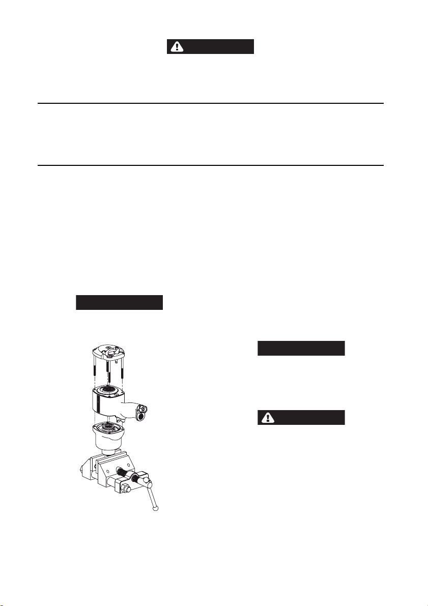
1. Unscrew and remove the four Backcap Bolts (12).
2. Lift the assembled Motor Housing (1) off of the Hammer Case (35). Make sure that you hold the Backcap in position on the Housing and that the motor does not come out of the Housing.
5. Remove and discard the Reverse Valve O-Ring (28). Replace it with a new one when assembling the Reverse Valve.
6. Use a flat, thin blade screwdriver to remove the Reverse Lever Retaining Ring (1 7) and Reverse Lever Spring (18) from the Reverse Lever (16).
7. Remove the Reverse Lever from the Backcap.
EN-2 04584363_ed2
Disassembly of the Motor
1. Remove the four Backcap Bolts.
2. Remove the Backcap, Motor Clamp Washer (19) and Backcap Gasket from the Housing and set them aside on a clean bench. Discard the Backcap Gasket and replace it with a new one when assembling the tool.
3. Lift the Housing from the Hammer C ase . Place one hand over the rear of the Hou sing and t urn the Housing over so that the assembled motor can slide and be guide out of the Housing.
4. Place the assembled motor on a clean bench with the rotor spline facing upward.
5. Remove the Front End Plate (26) and Cylinder (25).
6. Remove the Rotor (22) from the Rear End Plate (21).
7. Remove the Vanes from the Rotor.
Assembly
General Instructions
1. Always press on the inner ring of a ball-type bearing when installing the bearing on a shaf t.
2. Always press on the outer ring of a ball-type bearing when pressing the bearing into a bearing recess.
3. Whenever grasping a tool or part in a vise, always use leather-covered or copper-covered vise jaws. Take extra care with threaded parts or housings.
4. Always clean every part and wipe every part with a thin film of oil before installation.
5. Apply a film of O-Ring lubricant to al l O-Ring s before final assembly.
6. Check every bearing for roughness. Sealed or shielded bearings should never be cleaned. Work grease thoroughly into every open bearing before installation.
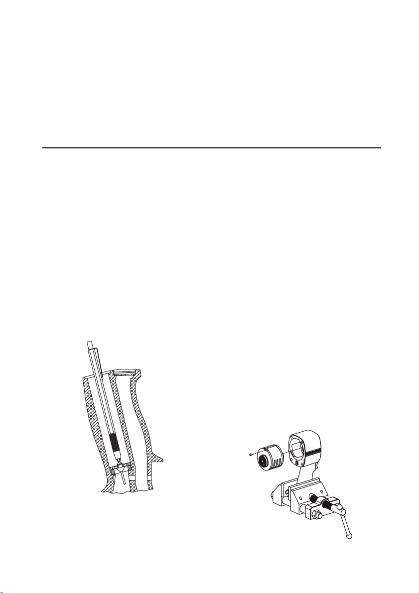
Assembly of the Throttle Mechanism
1. Install a new Throttle Valve Seat (2) by pushing it into position in the Housing (1) with a 13/16” dowel.
2. Insert the short end of the stem of the Throttle Valve (4) into the jaws of an expanding-type mechanical pencil. Allow the jaws to retract around the stem to secure it.
3. Install the Throttle Valve on the Valve Seat. See Dwg. TPD1919.
8. Inspect all motor parts including the Front Rotor Bearing (27) and Rear Rotor B earing (2 0) an d rep lace a ll worn or damaged parts.
Disassembly of the Throttle Mechanism
1. Unscrew and remove the Air Inlet Bushing (7).
2. Remove the Screen (6), Throttle Valve Spring (5) and Throttle Valve (4).
3. If the Throttle Valve Seat (2) requires replacem en t, i nse r t a hooked tool through the center of the Valve Seat. Catching the backside of the Seat with the hook, pull the Seat from the Housing.
4. Withdraw the Trigger Assembly (3) from the Housing.
5. Remove the Retaining Ring (10), Exhaust Deflector (11) and Muffler.
5. Install the Throttle Valve Spring (5), small end first, with the inside diameter of the small first coil around the hub of the Throttle Valve.
6. Coat the Inlet Bushing O-Ring (8) with O-Ring lubricant and install it on the Inlet Bushing (7).
7. Screw the Inlet bushing into the Housing until snug and tighten to 55-60 ft. lbs. (75-81 Nm) torque.
8. Wipe the stem of the Trigger Assembly (3) with light grease and insert the stem of the Trigger into the trigger bore in the Housing until it snaps into place on the Throttle Valve.
Assembly of the Motor
1. Pack the Front Rotor Bearing (27) and Rear Rotor Bearing (20) with the recommended grease. Install the Front Rotor Bearing in the Front End Plate (26) and the Rear Rotor Bearing in the Rear End Plate (21).
2. Slide the assembled Rear End Plate and Rear Rotor Bearing on the hub of the Rotor (22).
3. Set the assembled Rear End Plate and Rotor on a clean surface with the spline of the Rotor pointing upward.
4. Insert the Vanes (23) in the vane slots on the Rotor.
5. Install the Front and Rear Cylinder Dowels (24) in the Cylinder (25).
6. Slide the Cylinder over the R ot or and Vanes making sure that the Rear Cylinder Dowel enters the notch in the outside diameter of the Rear End Plate.
7. Install the assembled Front End Plate and Bearing over the front, splined end of the Rotor making sure that the front Cylinder Dowel fits into the notch in the outside diameter of the Front End Plate.
8. Grasp the Housing with one hand and set it upside down
on its top. With the other hand, carefully guide the motor
assembly into the Housing, making sure that the side of the
motor assembly containing the Cylinder Dowels is oriented
to the top of the Housing. Install Locating Pin (21A) into
Housing and Rear End Plate. See Dwg. TPD1923-1.
(Dwg. TPD1919)
4. As an alternate assembly procedure, drop the Throttle Valve, long stem first, into th e inlet p assage. If th e throttle Valve does not sit squarely on the Throttle valve S eat, shake the Handle until it seats.
(Dwg. TPD1923-1)
04584363_ed2 EN-3
 Loading...