

Ingersoll-Rand 2131, 2131S, 2131-2, 2131S-2, 2131FRC-2 Instructions Manual
03539871
Form P7106
Edition 6
November, 1999
TPD1346
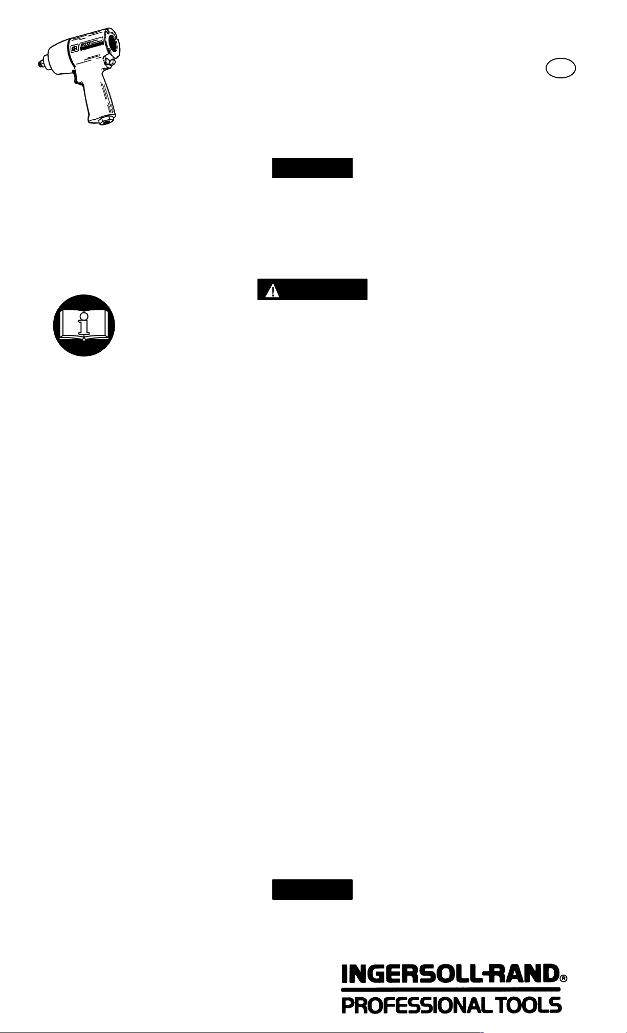
INSTRUCTIONS FOR
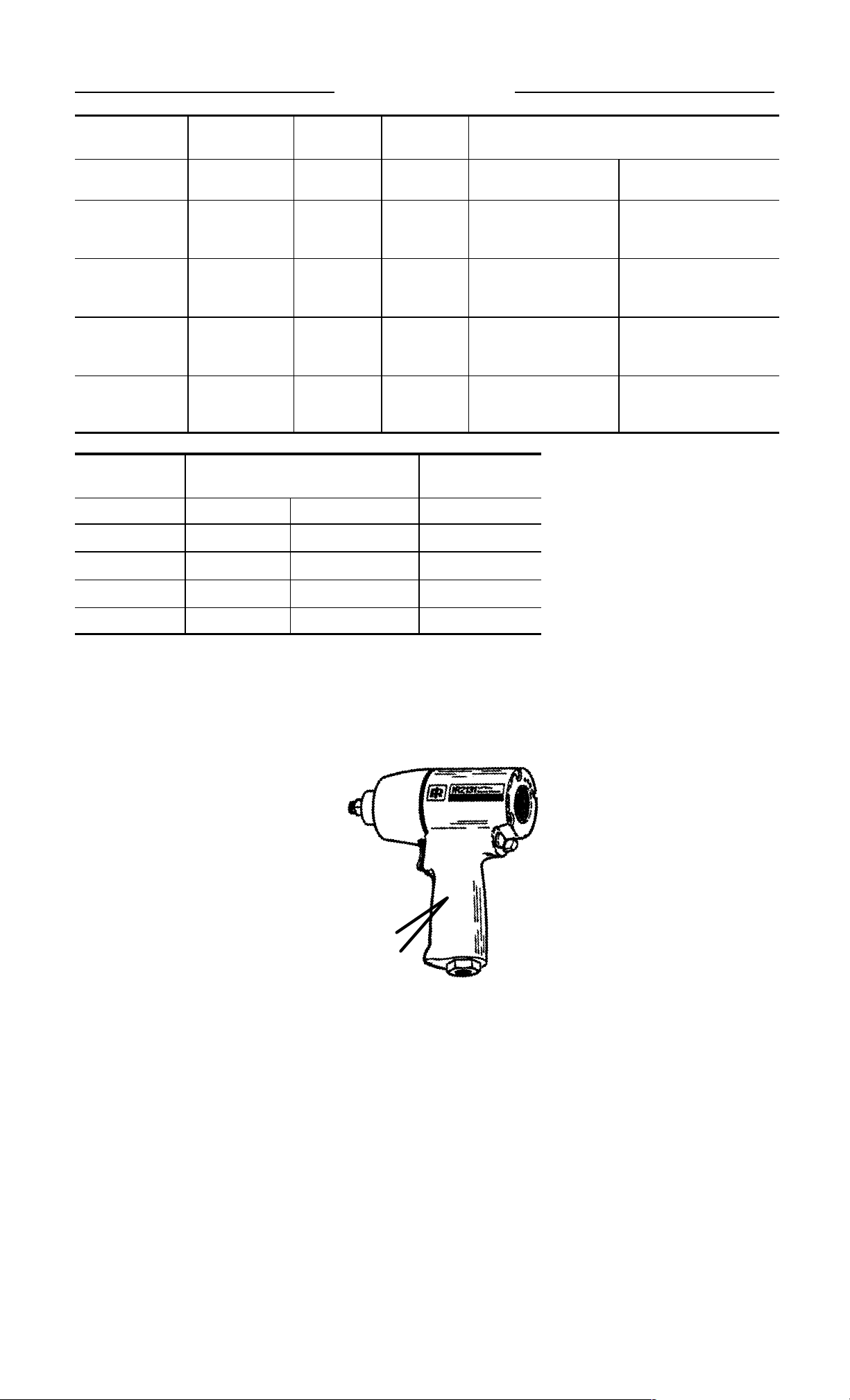
MODELS 2131, 2131S, 2131–2 AND 2131S–2
ULTRA DUTY AUTOMOTIVE IMPACT WRENCHES
Models 2131, 2131S, 2131–2 and 2131S–2 Impact Wrenches are designed for use in
general automotive repair, tire service and heavy duty fleet applications.
Ingersoll–Rand is not responsible for customer modification of tools for applications
on which Ingersoll–Rand was not consulted.
IMPORTANT SAFETY INFORMATION ENCLOSED.
READ THIS MANUAL BEFORE OPERATING TOOL.
IT IS THE RESPONSIBILITY OF THE EMPLOYER TO PLACE THE INFORMATION
IN THIS MANUAL INTO THE HANDS OF THE OPERATOR.
FAILURE TO OBSERVE THE FOLLOWING WARNINGS COULD RESULT IN INJURY.
GB
PLACING TOOL IN SERVICE
• Always operate, inspect and maintain this tool in
accordance with all regulations (local, state,
federal and country), that may apply to hand
held/hand operated pneumatic tools.
• For safety, top performance, and maximum
durability of parts, operate this tool at 90 psig
(6.2 bar/620 kPa) maximum air pressure at the
inlet with 3/8” (10 mm) inside diameter air supply
hose.
• Always turn off the air supply and disconnect the
air supply hose before installing, removing or
adjusting any accessory on this tool, or before
performing any maintenance on this tool.
• Do not use damaged, frayed or deteriorated air
hoses and fittings.
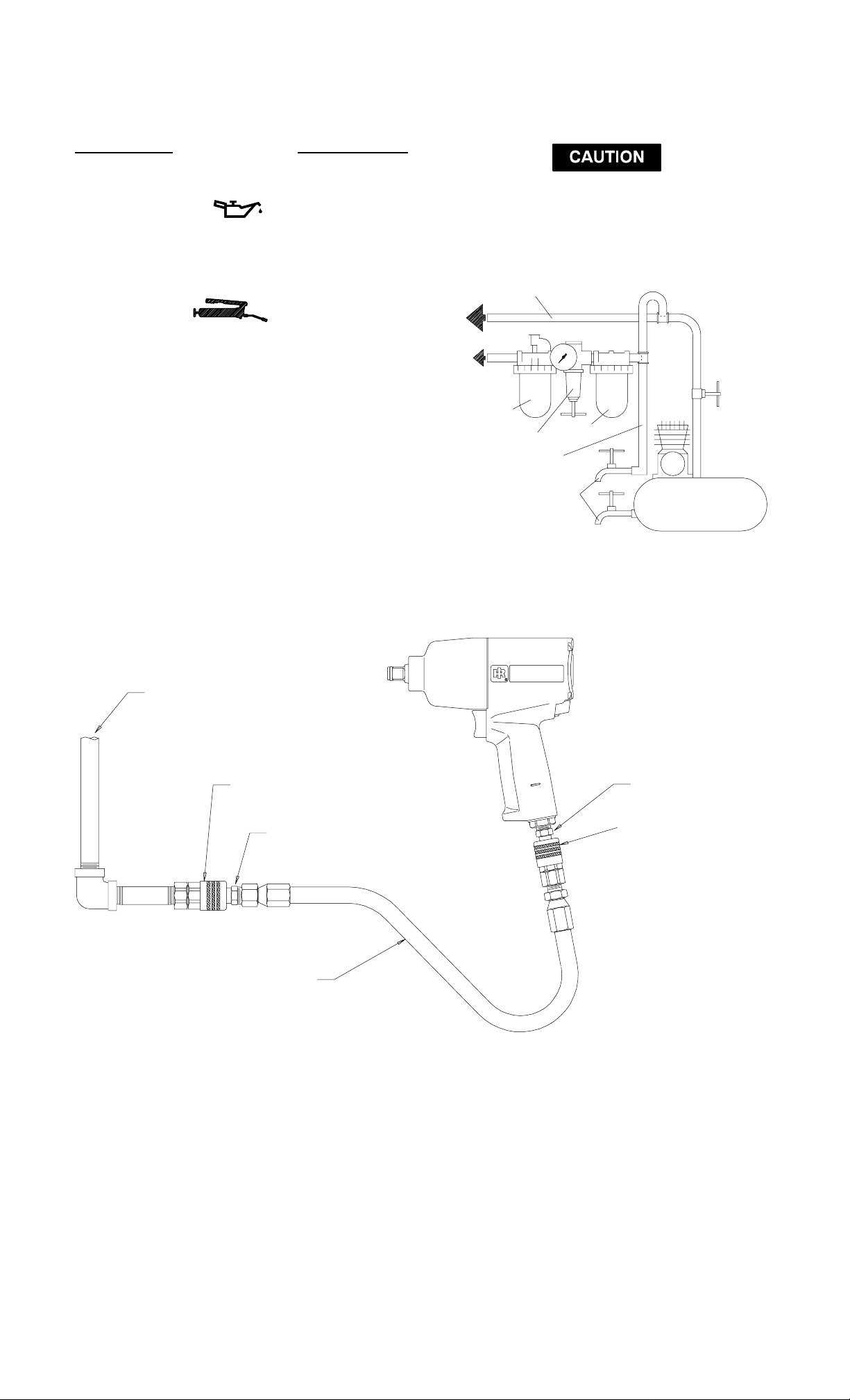
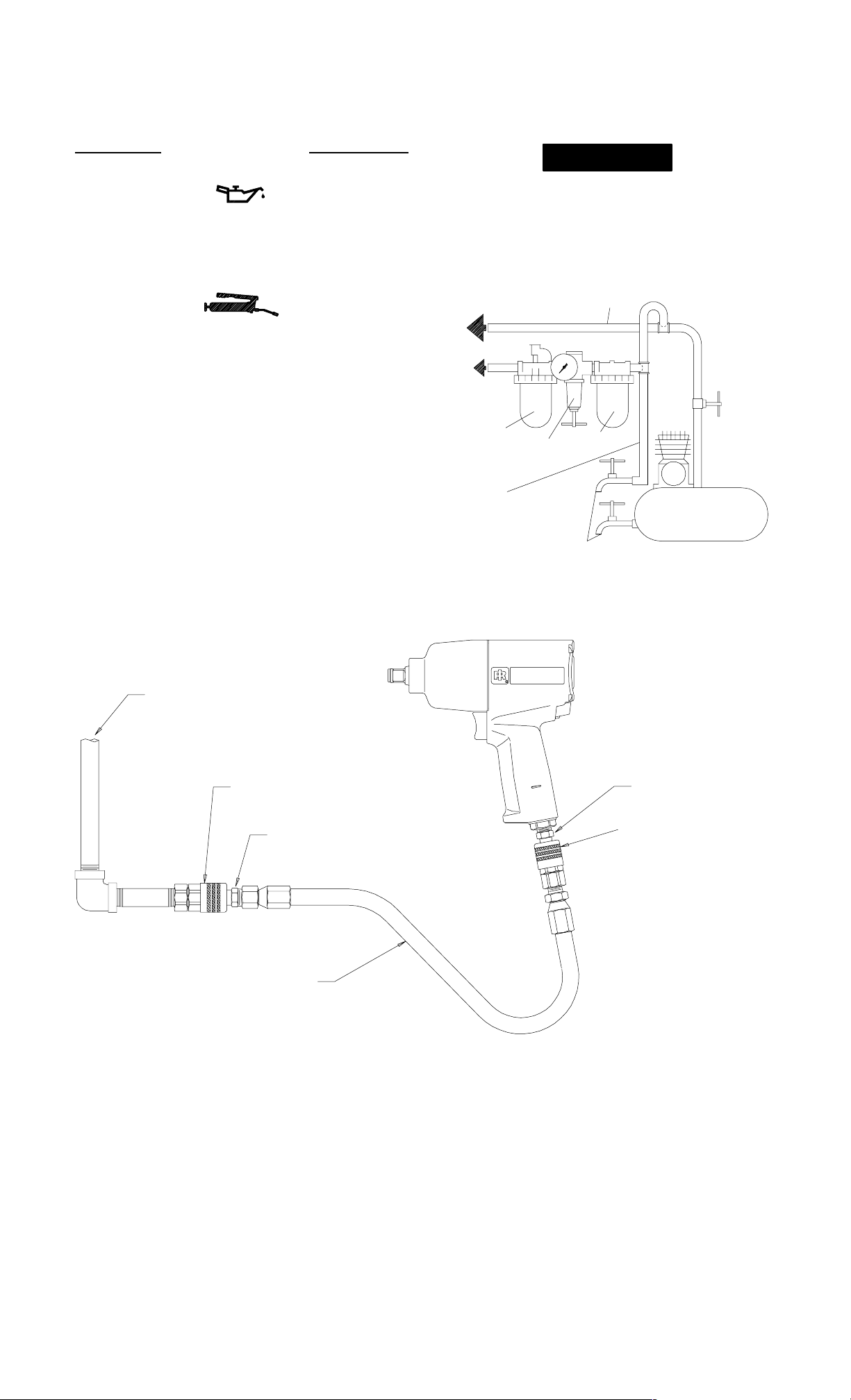
• Be sure all hoses and fittings are the correct size
and are tightly secured. See Dwg. TPD905–1 for a
typical piping arrangement.
• Always use clean, dry air at 90 psig maximum air
pressure. Dust, corrosive fumes and/or excessive
moisture can ruin the motor of an air tool.
• Do not lubricate tools with flammable or volatile
liquids such as kerosene, diesel or jet fuel.
• Do not remove any labels. Replace any damaged
label.
• The use of a hose whip is recommended. A coupler
connected directly to the air inlet increases tool
bulk and decreases tool maneuverability.
• For maximum performance, the coupler on the
wall should be the next size larger than the coupler
used on the tool. The coupler closest to the tool
should not be less than the proper air supply hose
size.
USING THE TOOL
• Always wear eye protection when operating or
performing maintenance on this tool.
• Always wear hearing protection when operating
this tool.
• Keep hands, loose clothing and long hair away
from rotating end of tool.
• Note the position of the reversing lever before
operating the tool so as to be aware of the direction
of rotation when operating the throttle.
• Anticipate and be alert for sudden changes in
motion during start up and operation of any power
tool.
• Keep body stance balanced and firm. Do not
overreach when operating this tool. High reaction
torques can occur at or below the recommended
air pressure.
• Tool shaft may continue to rotate briefly after
throttle is released.
• Air powered tools can vibrate in use. Vibration,
repetitive motions or uncomfortable positions may
be harmful to your hands and arms. Stop using
any tool if discomfort, tingling feeling or pain
occurs. Seek medical advice before resuming use.
• Use accessories recommended by Ingersoll–Rand.
• Use only impact sockets and accessories. Do not
use hand (chrome) sockets or accessories.
• Impact wrenches are not torque wrenches.
Connections requiring specific torque must be
checked with a torque meter after fitting with an
impact wrench.
• This tool is not designed for working in explosive
atmospheres.
• This tool is not insulated against electric shock.
The use of other than genuine Ingersoll–Rand replacement parts may result in safety hazards, decreased tool
performance, and increased maintenance, and may invalidate all warranties.
Repairs should be made only by authorized trained personnel. Consult your nearest Ingersoll–Rand Authorized
Servicenter.
Refer All Communications to the Nearest
Ingersoll–Rand Office or Distributor.
Ingersoll–Rand Company 1999
Printed in U.S.A.
W ARNING LABEL IDENTIFICATION
FAILURE TO OBSERVE THE FOLLOWING WARNINGS COULD RESULT IN INJURY.
WARNING
Always wear eye protection
when operating or performing maintenance on this tool.
WARNING
Air powered tools can vibrate
in use. Vibration, repetitive
motions or uncomfortable
positions may be harmful to
your hands and arms. Stop
using any tool if discomfort,
tingling feeling or pain occurs.
Seek medical advice before resuming use.
90 psig
(6.2bar/620kPa)
WARNING
Keep body stance balanced
and firm. Do not overreach
when operating this tool.
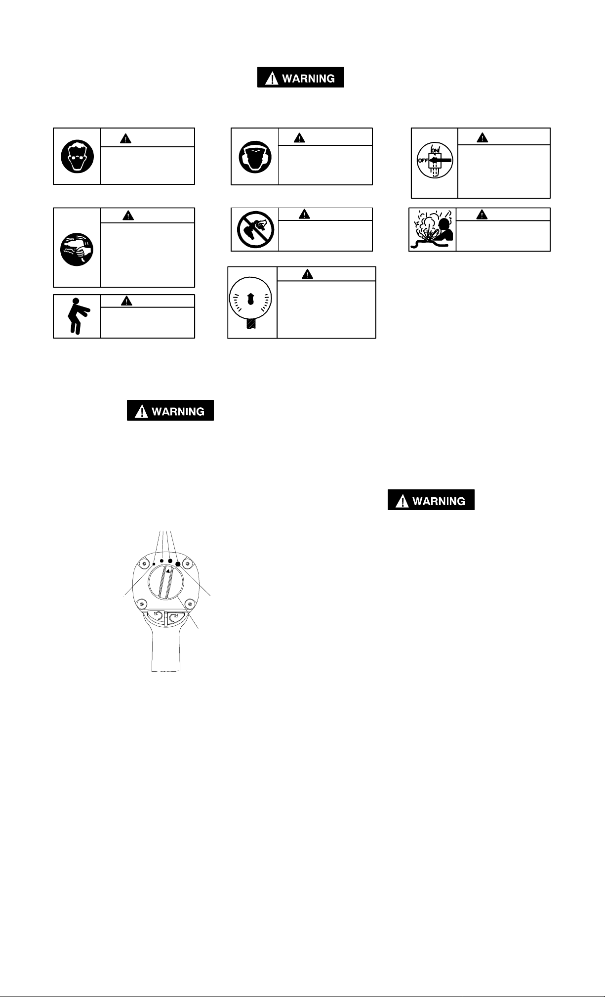
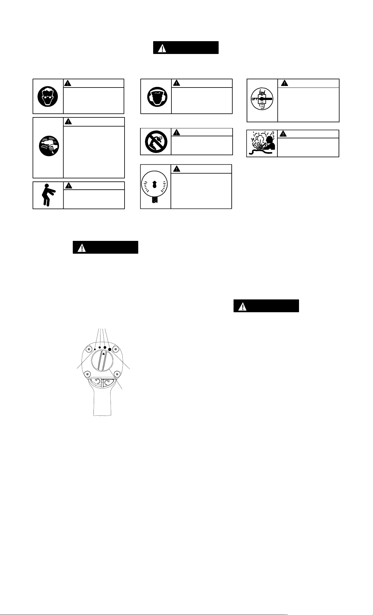
USING THE POWER MANAGEMENT SYSTEM
Air wrenches are not torque control devices. Fasteners
with specific torque requirements must be checked
with suitable torque measuring devices after
installation with an air wrench.
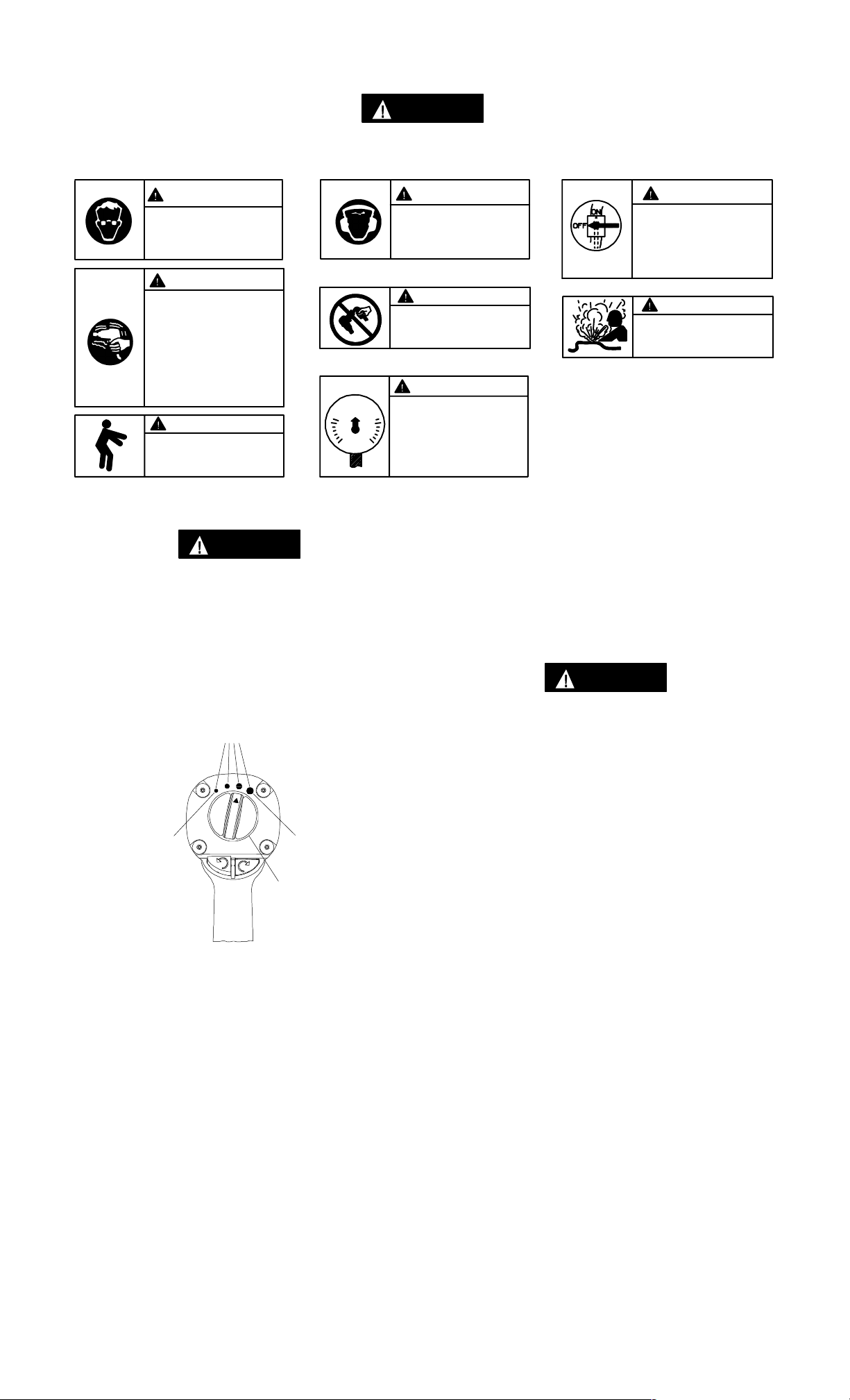
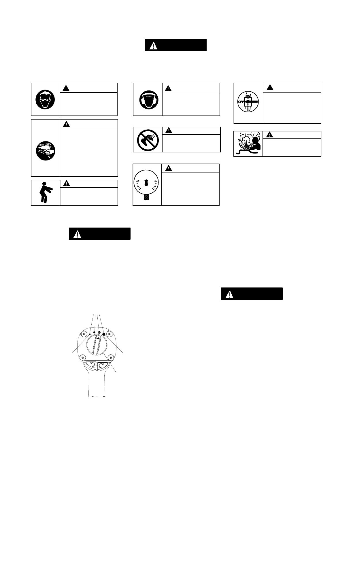
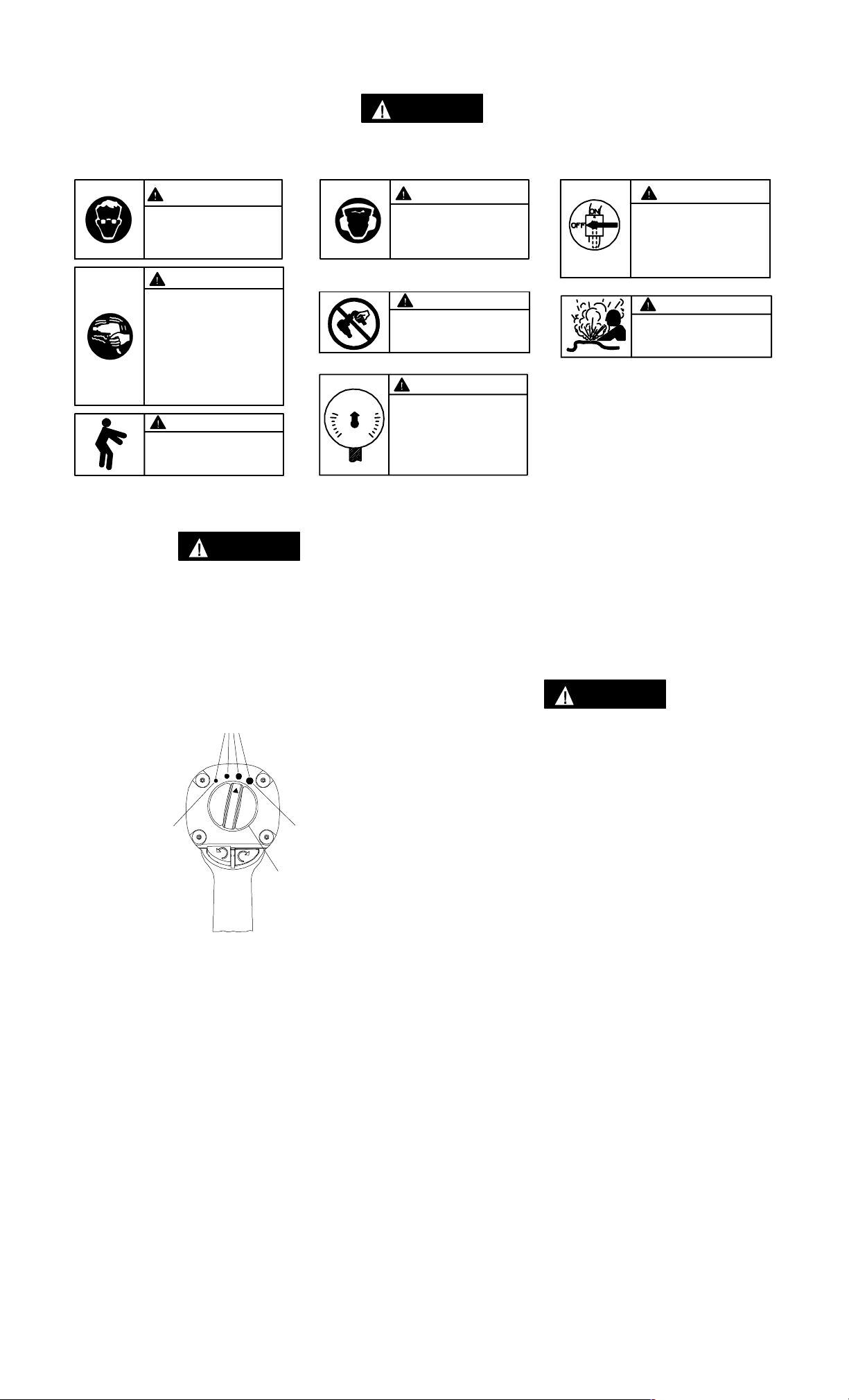
MODEL 2131 AND 2131–2 POWER
MANAGEMENT SYSTEM
POWER SETTING INDICA TORS
MAXIMUMMINIMUM
POWER
MANAGEMENT
DIAL
WARNING
Always wear hearing
protection when operating
this tool.
WARNING
Do not carry the tool by the
hose.
WARNING
Operate at 90 psig (6.2 bar/
620 kPa) Maximum air pressure.
Models 2131 and 2131–2 Impact Wrenches incorporate a
Power Management System that allows the operator to
select four power output settings. These settings range
from minimum power output through maximum power
output in the forward direction only. The Air Wrench will
always operate at maximum power output in the reverse
direction, no matter what power output level is selected.
The four power setting indicators of increasing size on
the rear of the housing indicate increasing power
output levels, are for reference only and DO NOT
denote a specific power output. The smallest power
setting indicator designates minimum power output,
the two middle power setting indicators denote medium
power outputs and the largest power setting indicator
denotes maximum power output.
The power output can be further reduced in forward
or reverse by using the variable throttle. Air supply
systems which do not deliver adequate air pressure can
affect power output at all settings.
WARNING
Always turn off the air supply and disconnect the air
supply hose before installing, removing or adjusting
any accessory on this tool,
or before performing any
maintenance on this tool.
WARNING
Do not use damaged, frayed
or deteriorated air hoses
and fittings.
(Dwg. TPD1339)
2
PLACING TOOL IN SERVICE
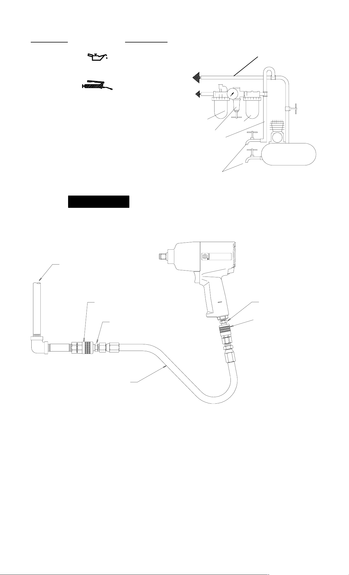
LUBRICATION
Ingersoll–Rand No. 50
Ingersoll–Rand No. 115–1LB for routine external
lubrication of the impact mechanism through the Hammer
Case Grease Fitting.
Do not mark any nonmetallic surface on this tool with
customer identification codes. Such actions could affect
tool performance.
MAIN LINES 3 TIMES
AIR TOOL INLET SIZE
TO
AIR
SYSTEM
TO
AIR
TOOL
Use Ingersoll–Rand No. 105–1LB or Ingersoll–Rand
105–8LB when disassembling and assembling the impact
mechanism.
Always use of an air line lubricator with these tools.
We recommend the following Filter–Lubricator–Regulator
Unit:
For USA – No. C18–03–FKG0–28
For International – C18–C3–FKG0
AIR SUPPLY (FROM COMPRESSOR)
3/8” COUPLER OR LARGER
(I–R PART NO. MSCF33)
I–R PART NO. MSPM32 (MALE)
I–R PART NO. MSPF32 (FEMALE)
LUBRICATOR
REGULATOR
BRANCH LINE 2 TIMES
AIR TOOL INLET SIZE
DRAIN REGULARLY
FILTER
COMPRESSOR
(Dwg. TPD905–1)
I–R PART NO. MSPM32
3/8” COUPLER OR LARGER
(I–R PART NO. MSCF32)
3/8” AIR HOSE
WITH 1/4” NPT FITTINGS
(Dwg. TPD1674–2)
3
PLACING TOOL IN SERVICE
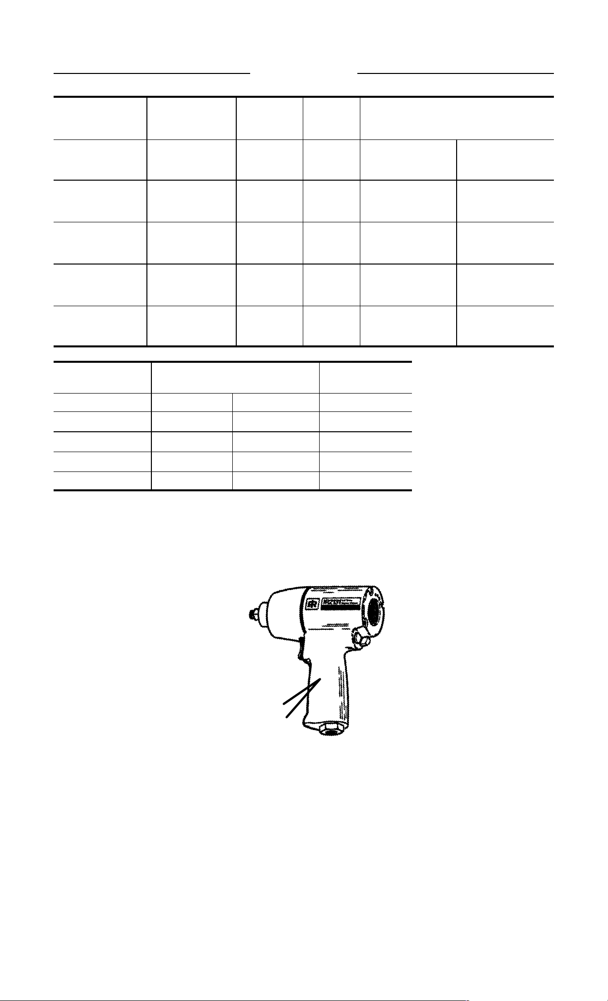
SPECIFICATIONS
Model Type of
Handle
Drive Impacts per
min.
Recommended
Torque Range
Forward
ft–lb (Nm)
2131 pistol grip 1/2” 1,250 50–400 [450 Max.]
(68–542 [610 Max.] )
2131–2 pistol grip 1/2”
1,250 50–400 [450 Max.]
(2” ext.)
(68–542 [610 Max.] )
2131S pistol grip 1/2” 1,250 50–400 [450 Max.]
(68–542 [610 Max.] )
2131S–2 pistol grip 1/2”
1,250 50–400 [450 Max.]
(2” ext.)
(68–542 [610 Max.] )
Model Sound Level
dB (A)
Pressure •Power m/s
♦Vibrations
Level
2
2131 95.5 108.5 5.7
Reverse
ft–lb (Nm)
550 [600 Max.]
(746 [813 Max.] )
550 [600 Max.]
(746 [813 Max.] )
550 [600 Max.]
(746 [813 Max.] )
550 [600 Max.]
(746 [813 Max.] )
2131–2 95.5 108.5 5.7
2131S 87.2 100.2 4.9
2131S–2 87.2 100.2 4.9
Tested in accordance with ANSI S5.1–1971 at free speed
♦ Tested to ISO8662–1 loaded with frictionbrake to 9 RPM
• ISO3744
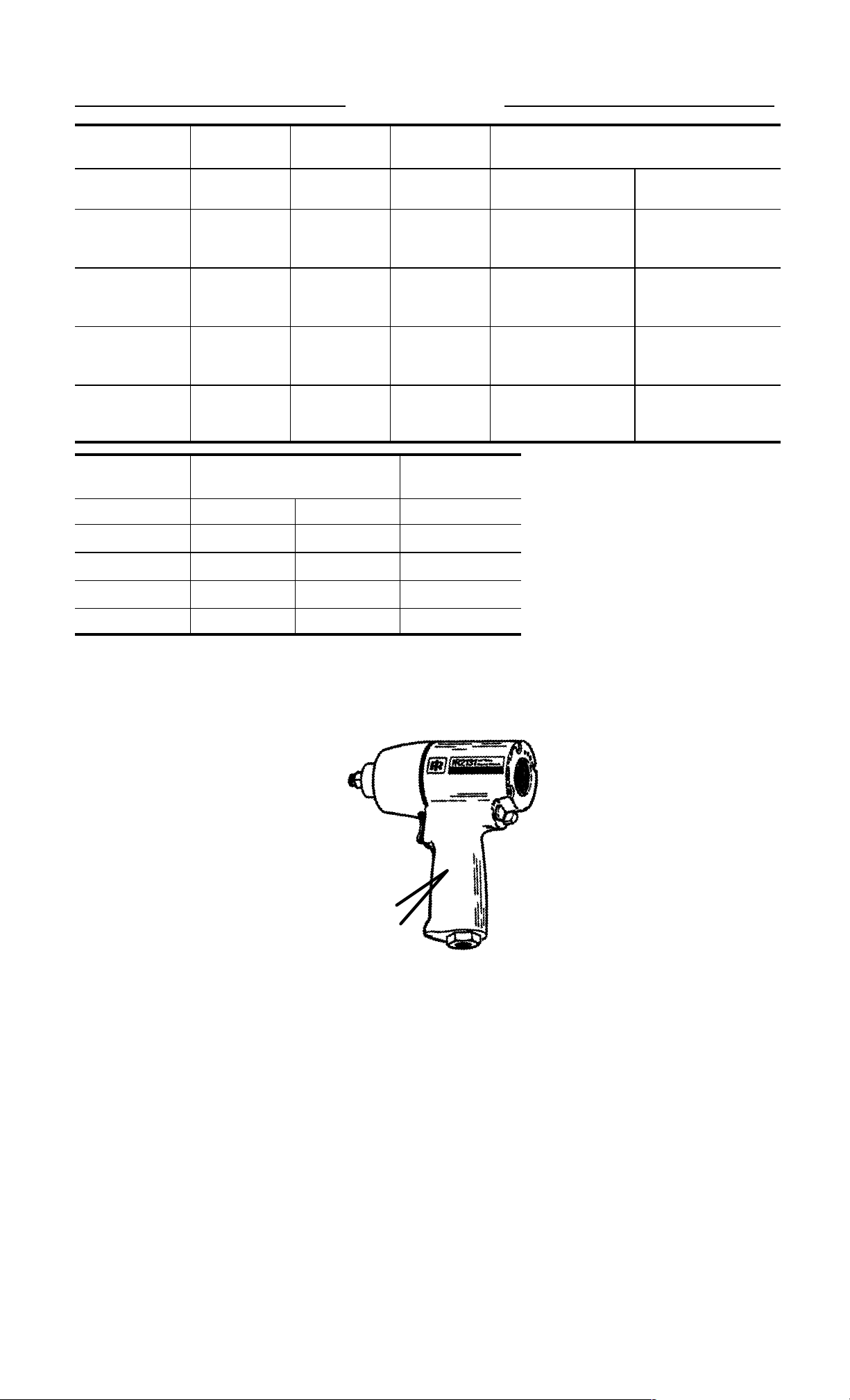
2131
TPD1885
Letter/Number
Date Code
Location
A __ __ __ __
A __ __ __ __
4
DECLARATION OF CONFORMITY
We
Ingersoll–Rand, Co.
(supplier’s name)
78192 Trapppes Cedex France
(address)
declare under our sole responsibility that the product,
Models 2131, 2131S, 2131–2 and 2131S–2 Ultra Duty Impact Wrenches
to which this declaration relates, is in compliance with the provisions of
98/37/EC
By using the following Principle Standards:
ISO8662
Directives.
Serial No. Range
D. Vose Kevin R. Morey
Name and signature of authorised persons Name and signature of authorised persons
November, 1999
Date Date
(1994 → ) XUA XXXXX →
November, 1999
SAVE THESE INSTRUCTIONS. DO NOT DESTROY.
When the life of the tool has expired, it is recommended that the tool be disassembled,
degreased and parts be separated by material so that they can be recycled.
5
03539871
Manuel P7106
TPD1346
Révision 6
Novembre, 1999
MODE D’EMPLOI DES
F
CLÉS À CHOCS AUTOMOBILES SÉRIE EXTRA
FORTE MODÈLES 2131, 2131S, 2131–2 ET 2131S–2
NOTE
Les clés à chocs Modèles 2131, 2131S, 2131–2 et 2131S–2 sont destinées aux
réparations automobiles générales, à l’entretien des pneus et aux applications de parc
automobile nécessitant des couples élevés.
Ingersoll–Rand ne peut être tenu responsable de la modification des outils par le client
pour les adapter à des applications qui n’ont pas été approuvées par Ingersoll–Rand.
ATTENTION
D’IMPORTANTES INFORMATIONS DE SÉCURITÉ SONT JOINTES.
LIRE CE MANUEL AVANT D’UTILISER L’OUTIL.
L’EMPLOYEUR EST TENU DE COMMUNIQUER LES INFORMATIONS
DE CE MANUEL AUX EMPLOYÉS UTILISANT CET OUTIL.
LE NON RESPECT DES AVERTISSEMENTS SUIVANTS PEUT CAUSER DES BLESSURES.
MISE EN SERVICE DE L’OUTIL
• Cet outil doit toujours être exploité, inspecté et
entretenu conformément à toutes les
réglementations (locales, départementales,
fédérales et nationales), applicables aux outils
pneumatiques tenus/commandés à la main.
• Pour la sécurité, les performances optimales et la
durabilité maximale des pièces, cet outil doit être
connecté à une alimentation d’air comprimé de
6,2 bar (620 kPa) maximum à l’entrée, avec un
flexible de 10 mm de diamètre intérieur.
• Couper toujours l’alimentation d’air comprimé et
débrancher le flexible d’alimentation avant
d’installer, déposer ou ajuster tout accessoire sur
cet outil, ou d’entreprendre une opération
d’entretien quelconque sur l’outil.
• Ne pas utiliser des flexibles ou des raccords
endommagés, effilochés ou détériorés.
• S’assurer que tous les flexibles et les raccords sont
correctement dimensionnés et bien serrés. Voir
Plan TPD905–1 pour un exemple type
d’agencement des tuyauteries.
• Utiliser toujours de l’air sec et propre à une
pression maximum de 6,2 bar. La poussière, les
fumées corrosives et/ou une humidité excessive
peuvent endommager le moteur d’un outil
pneumatique.
• Ne jamais lubrifier les outils avec des liquides
inflammables ou volatiles tels que le kérosène, le
gasol ou le carburant d’aviation.
• Ne retirer aucune étiquette. Remplacer toute
étiquette endommagée.
• L’utilisation d’un flexible suspendu est
recommandée. Un raccord connecté directement
au raccord d’admission augmente le poids de
l’outil et réduit donc sa manoeuvrabilité.
• Pour obtenir les performances maximales, le
raccord mural doit être d’un diamètre
immédiatement supérieur à celui du raccord utilisé
sur l’outil. Le raccord le plus proche de l’outil ne
doit pas être inférieur au diamètre du flexible
d’alimentation correct.
UTILISATION DE L’OUTIL
• Porter toujours des lunettes de protection pendant
l’utilisation et l’entretien de cet outil.
• Porter toujours une protection acoustique pendant
l’utilisation de cet outil.
• Tenir les mains, les vêtements flous et les cheveux
longs, éloignés de l’extrémité rotative de l’outil.
• Noter la position du levier d’inversion avant de
mettre l’outil en marche de manière à savoir dans
quel sens il va tourner lorsque la commande est
actionnée.
• Prévoir, et ne pas oublier, que tout outil motorisé
est susceptible d’à–coups brusques lors de sa mise
en marche et pendant son utilisation.
• Garder une position équilibrée et ferme. Ne pas se
pencher trop en avant pendant l’utilisation de cet
outil. Des couples de réaction élevés peuvent se
produire à, ou en dessous, de la pression d’air
recommandée.
• La rotation des accessoires de l’outil peut
continuer pendant un certain temps après le
relâchement de la gâchette.
• Les outils pneumatiques peuvent vibrer pendant
l’exploitation. Les vibrations, les mouvements
répétitifs et les positions inconfortables peuvent
causer des douleurs dans les mains et les bras.
N’utiliser plus d’outils en cas d’inconfort, de
picotements ou de douleurs. Consulter un médecin
avant de recommencer à utiliser l’outil.
• Utiliser les accessoires recommandés par
Ingersoll-Rand.
• N’utiliser que les douilles et les accessoires pour
clés à chocs. Ne pas utiliser les douilles et
accessoires (chromés) de clés manuelles.
• Les clés à chocs ne sont pas des appareils
dynamométriques. Les connexions nécessitant un
couple de serrage spécifique doivent être vérifiées
avec un mesureur de couple après avoir été
assemblées avec une clé à chocs.
• Cet outil n’est pas conçu pour fonctionner dans des
atmosphères explosives.
• Cet outil n’est pas isolé contre les chocs électriques.
NOTE
L’utilisation de rechanges autres que les pièces d’origine Ingersoll–Rand peut causer des risques d’insécurité, réduire les
performances de l’outil et augmenter l’entretien, et peut annuler toutes les garanties.
Les réparations ne doivent être effectuées que par des réparateurs qualifiés autorisés. Consultez votre Centre de Service
Ingersoll–Rand le plus proche.
Adressez toutes vos communications au Bureau
Ingersoll–Rand ou distributeur le plus proche.
Ingersoll–Rand Company 1999
Imprimé aux É.U.
SIGNIFICATION DES ÉTIQUETTES D’AVERTISSEMENT
ATTENTION
LE NON RESPECT DES AVERTISSEMENTS SUIVANTS PEUT CAUSER DES BLESSURES
ATTENTION ATTENTION
Porter toujours des lunettes
de protection pendant
l’utilisation et l’entretien de
cet outil.
ATTENTION
Les outils pneumatiques
peuvent vibrer pendant
l’exploitation. Les vibrations,
les mouvements répétitifs et les
positions inconfortables
peuvent causer des douleurs
dans les mains et les bras.
N’utiliser plus d’outils en cas d’inconfort, de picotements ou
de douleurs. Consulter un
médecin avant de recommencer
à utiliser l’outil.
90 psig
(6.2bar/620kPa)
ATTENTION
Garder une position équilibrée et
ferme. Ne pas se pencher trop
en avant pendant
l’utilisation de cet outil.
UTILISATION DU SYSTÈME DE GESTION DE PUISSANCE
ATTENTION
Les clés pneumatiques ne sont pas des dispositifs de
contrôle de couple. Les fixations ayant des exigences
spécifiques de couple doivent être contrôlées avec des
dispositifs dynamométriques appropriés après avoir été
assemblées avec une clé pneumatique.
SYSTÈME DE GESTION DE PUISSANCE
MODÈLES 2131 ET 2131–2
INDICATEURS DE RÉGLAGE DE PUISSANCE
MAXIMUMMINIMUM
CADRAN DE GESTION
DE PUISSANCE
ATTENTION
Porter toujours une
protection acoustique pendant l’utilisation de cet
outil.
ATTENTION
Ne pas transporter l’outil
par son flexible.
Couper toujours l’alimentation
d’air comprimé et débrancher le
flexible d’alimentation avant
d’installer, déposer ou ajuster
tout accessoire sur cet outil, ou
d’entreprendre une opération
d’entretien quelconque sur l’outil.
ATTENTION
Ne pas utiliser des flexibles ou
des raccords endommagés, effilochés ou détériorés.
ATTENTION
Utiliser de l’air comprimé
à une pression maximum
de 6,2 bar (620 kPa).
Les clés à chocs Modèles 2131 et 2131–2 sont équipées
d’un système de gestion de puissance qui permet à
l’opérateur de sélectionner quatre réglages de puissance.
Ces réglages vont de la puissance minimum à la puissance
maximum en marche avant seulement. La clé
pneumatique fonctionnera toujours à la puissance
maximum en desserrage, quel que soit le niveau de
puissance sélectionné.
ATTENTION
Les quatre indicateurs de réglage de puissance de taille
croissante sur l’arrière du corps indiquent les niveaux
croissants de puissance à titre de référence seulement,
et NE DÉNOTE PAS une puissance spécifique. Le plus
petit indicateur de puissance indique la puissance
minimum, les deux indicateurs du centre indiquent des
puissances moyennes, et le plus gros indicateur indique
la puissance maximum.
La puissance peut être encore plus réduite en serrage
ou desserrage à l’aide de la commande variable de mise
en marche. Les circuits d’air comprimé ne fournissant
pas une pression d’air adéquate peuvent affecter la
puissance fournie à toutes les positions de réglage.
(Plan TPD1339)
7
MISE EN SERVICE DE L’OUTIL
LUBRIFICATION
Ingersoll–Rand No. 50
Ingersoll–Rand No. 115–1LB pour une lubrification
extérieure normale du mécanisme de chocs par
l’intermédiaire du raccord de graissage du carter de
marteau.
Ingersoll–Rand No. 105–1LB ou Ingersoll–Rand
No. 105–8LB pour le démontage et l’assemblage du
mécanisme de chocs.
Utiliser toujours un lubrificateur avec ces outils. Nous
recommandons l’emploi du filtre–régulateur–lubrificateur
suivant:
É.U. – No. C18–03–FKG0–28
International – No. C18–C3–FKG0
AVERTISSEMENT
VERS LE
RÉSEAU D’AIR
COMPRIMÉ
VERS
L’OUTIL
PNEU-
MATIQUE
LUBRIFICATEUR
RÉGULATEUR
LIGNE SECONDAIRE AU
MOINS 2 FOIS LA DIMEN-
SION DE L’ADMISSION
D’AIR DE L’OUTIL
VIDANGER
RÉGULIÈREMENT
FILTRE
TUYAUTERIE PRINCIPALE AU
MOINS 3 FOIS LA DIMEN-
SION DE L’ADMISSION D’AIR
DE L’OUTIL
COMPRESSEUR
(Plan TPD905–1)
Ne pas marquer les codes d’identification client sur les
surfaces non métalliques de cet outil. De telles actions
pourraient affecter les performances de l’outil.
ALIMENTATION D’AIR (DU COMPRESSEUR)
RACCORD 3/8” OU PLUS
(RÉF. I–R NO. MSCF33)
RÉF. I–R NO. MSPM32 (MÂLE)
RÉF. I–R NO. MSPF32 (FEMELLE)
RÉF. I–R NO. MSPM32
RACCORD 3/8” OU PLUS
(RÉF. I–R NO. MSCF32)
FLEXIBLE D’AIR COMPRIMÉ 3/8”
AVEC RACCORDS 1/4” NPT
(Plan TPD1674–2)
8
MISE EN SERVICE DE L’OUTIL
SPÉCIFICATIONS
Modèle Type de Poignée Entraîne-
ment
Coups par
minute
Gamme de couples
recommandée
Marche avant
ft–lb (Nm)
2131 poignée pistolet 1/2” 1.250 50/400” [450 max.]
(68/542” [610 max.] )
2131–2 poignée pistolet 1/2”
1.250 50/400” [450 max.]
2” ext.
(68/542” [610 max.] )
2131S poignée pistolet 1/2” 1.250 50/400” [450 max.]
(68/542” [610 max.] )
2131S–2 poignée pistolet 1/2”
1.250 50/400” [450 max.]
2” ext.
(68/542” [610 max.] )
Modèle Niveau de son
dB (A)
Pression Puissance m/s
♦Niveau de vibra-
tion
2
Marche
arrière
ft–lb (Nm)
550 (600 max.)
(746 [813 max.] )
550 (600 max.)
(746 [813 max.] )
550 (600 max.)
(746 [813 max.] )
550 (600 max.)
(746 [813 max.] )
2131 95,5 108,5 5,7
2131–2 95,5 108,5 5,7
2131S 87,2 100,2 4,9
2131S–2 87,2 100,2 4,9
Testé conformément à ANSI S5.1–1971 en vitesse libre
♦ Testé conformément à ISO8662–1 chargé avec frein à friction à 9 tours par minute
• ISO3744
2131
TPD1885
A __ __ __ __
Position du
Code Date
à Lettre/Chiffre
9
CERTIFICAT DE CONFORMITÉ
Nous
Ingersoll–Rand, Co.
(nom du fournisseur)
78192 Trappes Cedex France
(adresse)
déclarons sous notre seule responsabilité que le produit:
Clés à Chocs Automobiles Série Extra Forte
Modèles 2131, 2131S, 2131–2 et 2131S–2
objet de ce certificat, est conforme aux prescriptions des Directives:
98/37/CE
en observant les normes de principe suivantes:
ISO8662
No. Serie:
D. Vose Kevin R. Morey
Nom et signature des chargés de pouvoir Name and signature of authorised persons
Novembre 1999
Date Date
(1994 → ) XUA XXXXX →
Novembre 1999
NOTE
CONSERVEZ SOIGNEUSEMENT CES INSTRUCTIONS. NE PAS LES DÉTRUIRE.
A la fin de sa durée de vie, il est recommandé de démonter l’outil, de dégraisser les pièces et de les séparer en
fonction des matériaux de manière à ce que ces derniers puissent être recyclés.
10
03539871
Form–Nr. P7106
Ausgabe 6
November, 1999
TPD1346
BEDIENUNGSANLEITUNG FÜR
ULTRA–HOCHLEISTUNGS–SCHLAGSCHRAUBER
DER BAUREIHE 2131, 2131S, 2131–2 UND 2131S–2
HINWEIS
Schlagschrauber der Baureihe 2131, 2131S, 2131–2 und 2131S–2 werden eingesetzt für
allgemeine KFZ–Reparaturen, Rad– und Reifenwechsel und schwere Fahrzeugparkarbeiten.
Ingersoll–Rand lehnt jede Haftung für Veränderungen an Werkzeugen ab, die ohne vorherige
Rücksprache mit Ingersoll–Rand vo rgenomme n werd e n.
ACHTUNG
NACHFOLGEND WICHTIGE SICHERHEITSHINWEISE.
DIESE BETRIEBSANWEISUNG VOR INBETRIEBNAHME DES WERKZEUGES
UNBEDINGT LESEN.
DER ARBEITGEBER IST VERPFLICHTET, DIE IN DIESEM HANDBUCH GEGEBENEN
INFORMATIONEN DEM BEDIENER ZUGÄNGLICH ZU MACHEN.
DIE NICHTEINHALTUNG DIESER WARNHINWEISE KANN ZU VERLETZUNGEN FÜHREN.
D
INBETRIEBNAHME DES WERKZEUGES
• Das Werkzeug stets nach den örtlich und landesweit
geltenden Vorschriften für
handgehalte ne/ handbe tr ie be ne Druckluf twe rkz e uge
betreiben.
• Zur Erzielung höchster Sicherheit, Leistung und
Haltbarkeit der Teile sollte dieses Werkzeug mit
einem maxi ma le n Luftdruck von 6,2 bar/620 kPa am
Lufteinlaß und einem Luftzufuhrschlauch
10 mm Innendurchmesse r betri ebe n werden.
• Vor Montage, Demo ntage oder Verstellung von
Aufsetzteilen bzw. Wartung dieses Werkzeuges die
Druckluftve r sor gung allsei ti g abschalte n und
Druckluftsc hl auc h abschli eßen .
• Keine beschädigten, durchgescheuerten oder
abgenutzten Luftschläuche und Anschlüsse
verwenden.
• Darauf ac hten, daß alle Schläuche und Anschlüsse
die pa ssende Größe haben und korrekt befestigt sind.
In Zei c hnung TPD90 5–1 ist eine typi sche
Rohrleit ungsano r dnung abgebilde t.
• Stets saubere, troc kene Luft ver wende n und eine n
Luftdruck von 6,2 bar ver we nde n. Staub, ätzende
Dämpfe und/ode r Feuc hti gke it können den Motor
eines Druckluftwerkzeuges beschädigen.
• Die Werkzeug e nic ht mit brennbaren oder flüchtigen
Flüssigkeiten wie Ke rosi n und Diesel schmieren.
• Keine Schilder entfernen. Beschädigte Schilder
austauschen.
• Einsatz eine s Schlauchsc hutze s wird empfohl en.
Wird direkt am Lufteinlaß ei n Kuppler
angeschlossen, so wird dadurch die Werkzeugmasse
größer und die Werkzeugmanövrierfähigkeit
reduziert.
• Um maxima le Leistung zu gewährleisten, muß der
Koppler an der Wand gegenüber dem am Werkzeug
eingesetzten Koppler um eine Stufe größer sei n. De r
dem Werkzeug am nächsten gelegene Koppler darf
nicht kleiner sein als der jeweilige
Luftzufuhrschlauch.
WERKZEUGEIN SATZ
• Beim Betreiben oder Warten dieses Werkzeuges stets
Augenschutz tr age n.
• Beim Betreiben dieses Werkzeuges stets Gehörs chu tz
tragen.
• Hände, lose Beklei dungsstücke und lange Haare vom
rotierenden Ende des Werkzeuges fernhalten.
• Vor der Inbetrie bnahme auf die Positi on des
Umsteuerhebels achten, damit bei Betätigen der
Drossel di e Drehricht ung schon bekannt ist.
• Bei Start und Betrieb eines Werkzeuges auf
Rückschlag achten und darauf vorbereitet sein.
• Während des Be t re ibens für fe sten Halt sorgen und
den Körper nicht zu weit vor lehne n. Be i Be tri eb mit
empfohlenem oder niedrigerem Luftdruck können
hohe Reaktionsdrehmomente auftreten.
• Nach dem Losl assen des Drückers kann die Welle
des Werkzeugs noch kurz weiterdrehen.
• Druckluftbetriebene Werkzeuge können während des
Betrie bs vibri e re n. Vibratione n, häufige
gleichförmige Beweg ungen oder unbequem e
Positionen können schädlich für Hände und Arme
sein. Bei Unbehagen, Kribbeln oder Schmerzen das
Werkzeug nicht mehr benutzen. Vor dem erneuten
Arbeiten mit dem Werkzeug ärztliche Hilfe
aufsuchen.
• Stets von Ingersoll–Rand empf ohl ene s Zubehör
verwenden.
• Nur Schl ag schr aube r –Steckschlüssel und –Zubehör
verwenden. Keine Hand–Steckschlüssel (Chrom)
oder –Zubehör verwende n.
• Schlagschr aube r sind kei ne Drehmoment schr aube r.
Verbindungen, die ein bestimmt es Drehmoment
erfordern, müssen nach dem Anziehen mit dem
Schlagschra uber mit Hil fe ei nes
Drehmomentmeßgerätes überprüft werden.
• Das Werkzeug ist nicht für die Arbeit in explosiven
Atmosphären geeignet.
• Dieses Werkzeug ist nicht gegen elektrischen
Schlag isoliert.
HINWEIS
Die Verwendung von nicht Original–Ingersoll–Rand–Ersatzteilen kann Sicherheitsrisiken, verringerte Standzeit und
erhöhten Wartungsbedarf nach sich ziehen und alle Garantieleistungen ungültig machen.
Reparaturen sollen nur von geschultem Personal durchgeführt werden. Wenden Sie sich an Ihre nächste
Ingersoll–Rand– Niederlassung oder den autorisierten Fachhandel.
Wenden Sie sich bei Rückfragen an Ihre nächste Ingersoll–Rand–
Niederlassung oder den autorisierten Fachhandel.
Ingersoll–Rand Company 1999
Druck: USA
ANWEISUNGEN AUF WARNSCHILDERN
ACHTUNG
DIE NICHTEINHALTUNG DIESER WARNHINWEISE KANN ZU VERLETZUNGEN FÜHREN.
ACHTUNG
Beim Betreiben oder Warten
dieses Werkzeuges stets
Augenschutz tragen.
ACHTUNG
Druckluftbetriebene Werkzeuge
können während des Betriebs
vibrieren. Vibrationen, häufige
gleichförmige Bewegungen oder
unbequeme Positionen können
schädlich für Hände und Arme
sein. Bei Unbehagen, Kribbeln
oder Schmerzen das Werkzeug
nicht mehr benutzen. Vor dem
erneuten Arbeiten mit dem
Werkzeug ärztliche Hilfe aufsuchen.
90 psig
(6.2bar/620 kPa)
ACHTUNG
Während des Betreibens für
festen Halt sorgen und den Körper
nicht zu weit nach vorne beugen.
EINSATZ DES LEISTUNGSSTEUERUNGS–SYSTEMS
ACHTUNG
Druckluftschrauber sind nicht
drehmomentkontrolliert. Befestigungselemente mit
bestimmten Drehmomentanforderungen müssen nach
der Installation durch einen Druckluftschrauber mit
Hilfe eines geeigneten Drehmoment–Meßgerätes
überprüft werden.
ACHTUNG
Beim Betreiben dieses
Werkzeuges stets
Gehörschutz tragen.
ACHTUNG
Das Werkzeug nicht am
Schlauch tragen.
ACHTUNG
Vor Wartungsarbeiten oder
dem Austausch von Zubehör
ist das Werkzeug von der
Druckluftversorgung abzuschalten.
ACHTUNG
Keine beschädigten,
durchgescheuerten oder
abgenutzten Luftschläuche
und Anschlüsse verwenden.
ACHTUNG
Mit einem maximalen
Luftdruck von 6,2 bar/620
kPa (90 psig) betreiben.
Schlagschrauber der Modelle 2131 und 2131–2 verfügen
über ein Leistungssteuerungs–System, mit Hilfe dessen
der Bediener vier verschiedene Leistungseinstellungen
vornehmen kann. Die Einstellungen reichen bei
Vorwärtsrichtung von minimaler bis maximaler Leistung.
In Umkehrrichtung arbeitet der Druckluftschrauber stets
mit maximaler Leistung, unabhängig von der mit dem
Drehknopf eingestellten Leistung.
MODELL 2131 UND 2131–2
LEISTUNGSSTEUERUNGS–SYSTEM
ANZEIGEPUNKTE FÜR DIE LEISTUNGSEINSTELLUNG
MINIMUM
MAXIMUM
DREHKNOPF FÜR
LEISTUNGSSTEUERUNG
(Zeichn. TPD1339)
ACHTUNG
Die vier Anzeigepunkte für die Leistungseinstellung in
zunehmender Größe hinten auf dem Gehäuse bedeuten
höhere Leistung. Sie dienen jedoch lediglich der
Referenz und GEBEN NICHT bestimmte
Leistungswerte an. Der kleinste Anzeigepunkt steht für
minimale Leistung, die beiden mittleren für mittlere
Leistung und der größte Anzeigepunkt für maximale
Leistung des Werkzeuges. Die abgegebene Leistung
kann durch den Einsatz einer verstellbaren Drossel in
Vorwärts– oder Rückwärtsrichtung zusätzlich
verringert werden. Luftzufuhrsysteme, die nicht den
angemessenen Luftdruck liefern, können bei allen
Einstellungen Einfluß auf die Leistung haben.
12

INBETRIEBNAHME DES WERKZEUGES
SCHMIERUNG
Ingersoll–Rand Nr. 50
Zur routinemäßigen, externen Schmierung des
Schlagwerkes (am Hammergehäuse–Schmiernippel)
Ingersoll–Rand Öl Nr. 115–1LB verwenden.
Bei Zerlegung und Zusammenbau des Schlagwerkes
Ingersoll–Rand Öl Nr. 105–1LB oder Ingersoll–Rand
Öl Nr. 105–8LB verwenden.
Das Werkzeug stets mit einem Leitungsöler verwenden.
Es wird folgende Filter–Regler–Öler–Kombination
empfohlen:
Ingersoll–Rand Nr: C18–C3–FKG0
VORSICHT
Die nicht–metallische Oberfläche des Werkzeugs ist
keinesfalls mit Kunden–Identifikations–Merkmalen zu
versehen. Dies kann die Leistung des Werkzeuges
beeinträchtigen.
ZUM
DRUCKLUFTSYSTEM
ZUM
DRUCKLUFTWERKZEUG
ÖLER
NEBENROHRLEITUNG
MIT ZWEIFACHEM
DURCHMESSER DES
LUFTEINLASSES
REGELMÄSSIG
ABLASSEN
HAUPTROHRLEITUNG MIT DREIFACHEM
DURCHMESSER DES
LUFTEINLASSES
REGLER
FILTER
KOMPRESSOR
(Zeichn. TPD905–1)
LUFTZUFUHR (VOM KOMPRESSOR)
3/8” KOPPLER ODER GRÖSSER
(I–R TEIL–NR. MSCF33)
I–R TEIL–NR. MSPM32 (AUSSENGWINDE)
I–R TEIL–NR.. MSPF32 (INNENGEWINDE)
3/8” LUFTSCHLAUCH MIT
1/4” NPT ARMATUREN
I–R TEIL–NR. MSPM32
3/8” KOPPLER ODER GRÖSSER
(I–R TEIL–NR. MSCF32)
(Zeichn. TPD1674–2)
13
INBETRIEBNAHME DES WERKZEUGES
TECHNISCHE DATEN
Modell Griffart Antrieb Schläge/
Minute
Empfohlenes
Arbeitsdrehmoment
Vorwärts
ft–lb/Nm
2131 Pistolengriff 1/2” 1.250 50–400 (max. 450)
(68–542 [max. 610] )
2131–2 Pistolengriff 1/2”
1.250 50–400 (max. 450)
(2” Verl.)
(68–542 [max. 610] )
2131S Pistolengriff 1/2” 1.250 50–400 (max. 450)
(68–542 [max. 610] )
2131S–2 Pistolengriff 1/2”
1.250 50–400 (max. 450)
(2” Verl.)
(68–542 [max. 610] )
Modell Schallpegel
dB (A)
Druck •Leistung m/s
♦Schwingungs-
intensität
2
Rückwärts
ft–lb/Nm
550 (max. 600)
(746 [max. 813] )
550 (max. 600)
(746 [max. 813] )
550 (max. 600)
(746 [max. 813] )
550 (max. 600)
(746 [max. 813] )
2131 95,5 108,5 5,7
2131–2 95,5 108,5 5,7
2131S 87,2 100,2 4,9
2131S–2 87,2 100,2 4,9
Gemäß ANSI S5.1–1971 bei freier Drehzahl getestet
♦ Nach ISO8662–1 mit Reibungsbremse auf 9 U/min. getestet
• ISO3744
2131
TPD1885
A __ __ __ __
Buchstaben/
Zehlen–
Datencode
14
KONFORMITÄTSERKLÄRUNG
Wir
Ingersoll–Rand, Co.
(Name des Herstellers)
78192 Trappes Cedex France
(Adresse)
erklären hiermit, gemäß unserer alleinigen Verantwortung, daß die Geräte:
Ultra–Hochleistungs–Schlagschrauber
der Baureihe 2131, 2131S, 2131–2 und 2131S–2
auf die sich diese Erklärung bezieht, den Richtlinien:
98/37/EG
unter Anlehnung an die folgenden Grundnormen
entsprechen:
ISO8662
Serien–Nr.–Bereich:
D. Vose Kevin R. Morey
Name und Unterschrift der Bevollmächtigten Name und Unterschrift der Bevollmächtigten
November 1999
Datum Datum
(1994 → ) XUA XXXXX →
November 1999
HINWEIS
DIESE ANWEISUNGEN SIND SORGFÄLTIG AUFZUBEWAHREN. NICHT ZERSTÖREN.
Zur Entsorgung ist das Werkzeug vollständig zu demontieren, zu entfetten und nach Materialarten
getrennt der Wiederverwertung zuzuführen.
15
03539871
Modulo P7106
Edizione 6
Novembre 1999
ISTRUZIONI PER CHIAVI AD IMPULSI ULTRA
TPD1346
DUTY PER AUTOMEZZI MODELLI
2131, 2131S, 2131–2 E 2131S–2
AVVISO
Le chiavi ad impulsi modelli 2131, 2131S, 2131–2 e 2131S–2 sono state progettate per
l’uso di riparazione di autoveicoli, manutenzione dei pneumatici ed applicazioni havy
duty di fleet.
La Ingersoll–Rand non è responsabile delle modifiche apportate alle pompe dai clienti
per adattarli ad applicazioni per le quali la Ingersoll–Rand non sia stata interpellata.
AVVERTENZA
IMPORTANTE INFORMAZIONE DI SICUREZZA ACCLUSA.
LEGGERE IL PRESENTE MANUALE PRIMA DI USARE L’ATTREZZO.
È RESPONSABILITÀ DEL DATORE DI LAVORO DI METTERE QUEST’INFORMAZIONE
NELLE MANI DELL’OPERATORE.
LA MANCATA OSSERVANZA DELLE SEGUENTI AVVERTENZE PUÒ CAUSARE
LESIONI FISICHE.
I
MESSA IN SERVIZIO DELL’ATTREZZO
• Usare, ispezionare e mantenere sempre
quest’attrezzo secondo tutti i regolamenti (locali,
statali, federali e nazionale), che possano essere
applicabili agli attrezzi a mano pneumatici.
• Per sicurezza, massime prestazioni e massima
durabilità delle parti, usare quest’attrezzo ad una
massima pressione d’aria di 90 psig (6,2 bar/
620 kPa) all’ingresso con un flessibile di
alimentazione dell’aria con diametro interno di
3/8” (10 mm).
• Disinserire sempre l’alimentazione aria e staccare
il relativo tubo dall’attrezzo, prima di installare,
togliere o regolare qualsiasi accessorio, oppure
prima di eseguire qualsiasi operazione di
manutenzione dell’attrezzo.
• Non adoperare tubi e raccordi danneggiati,
consunti o deteriorati.
• Assicurarsi che tutti i tubi ed i raccordi siano delle
corrette dimensioni e saldamente serrati.
Consultare il disegno TPD905–1 per una tipica
disposizione dei tubi.
• Usare sempre aria pulita ed asciutta alla pressione
max di 90 psig. Polvere, fumi corrosivi e/o un
eccesso di umidità possono rovinare il motore di un
attrezzo pneumatico.
• Non lubrificare gli utensili con liquidi infiammabili
o volatili come kerosene, gasolio o combustibile per
aviogetti.
• Non togliere nessuna etichetta. Sostituire eventuali
etichette danneggiate.
• Si consiglia l’uso di un segmento di flessibile. Un
raccordo collegato direttamente all’ingresso
dell’aria aumenta il volume dell’attrezzo e ne
diminuisce la manovrabilità.
• Per massime prestazioni, il raccordo sul muro deve
essere della successiva dimensione maggiore di
quella del raccordo sull’attrezzo. Il raccordo più
vicino all’attrezzo non deve essere inferiore alla
corretta dimensione del flessibile
dell’alimentazione dell’aria.
COME USARE L’ATTREZZO
• Indossare sempre degli occhiali protettivi quando si
adopera questo attrezzo o se ne esegue la
manutenzione.
• Indossare sempre delle cuffie protettive quando si
adopera questo attrezzo.
• Tenere le mani, gli indumenti sciolti ed i capelli
lunghi distanti dall’estremità battente
dell’attrezzo.
• Notare la posizione della leva d’inversione prima
di azionare l’attrezzo in modo da essere consci
della direzione di ruotazione quando si aziona
l’immissione.
• Fare attenzione e cercare di anticipare improvvise
di azioni di movimento durante l’avviamento e
l’uso di qualsiasi utensile pneumatico.
• Nell’usare l’attrezzo, mantenere con il corpo una
posizione salda e ben bilanciata. Non sbilanciarsi
durante l’uso di questo attrezzo. Delle elevate
reazioni di coppia si possono verificare alla
pressione d’aria raccomandata o inferiore.
• Gli accessori dell’utensile potrebbe continuare a
funzionare brevemente dopo che è stata disinserita
l’immissione.
• Gli attrezzi pneumatici possono vibrare durante
l’uso. Le vibrazioni, i movimenti ripetitivi o le
posizioni scomode possono risultare dannosi per le
mani e le braccia. Interrompere l’uso dell’utensile
se si avvertono sintomi di disagio fisico, formicolio
o dolore. Interpellare un medico prima di
riprendere il lavoro.
• Usare accessori raccomandati dalla
Ingersoll–Rand.
• Usare solo boccole ed accessori ad impulso. Non
usare boccole a mano (cromate) o accessori.
• Le chiavi ad impulsi non sono chiavi
torsiometriche. Collegamenti che richiedono
specifiche coppie devono essere controllati con un
torsiometro l’installazione con una chiave
torsiometrica.
• Questo utensile non è stato progettato per operare
in atmosfere esplosive.
• Questo utensile non è isolato contro le scosse
elettriche.
AVVISO
L’uso di ricambi non originali Ingersoll–Rand potrebbe causare condizioni di pericolosità, compromettere le p restazioni
dell’attrezzo ed aumentare la necessità di manutenzione, inoltre potrebbe invalidare tutte le garanzie.
Le riparazioni devono essere effettuate soltanto da personale autorizzato e qualificato. Rivolgersi al più vicino centro di
assistenza tecnica Ingersoll–Rand.
Indirizzare tutte le comunicazioni al più vicino
concessionario od ufficio Ingersoll–Rand.
Ingersoll–Rand Company 1999
Stampato in U.S.A.
IDENTIFICAZIONE DELLE ETICHETTE DI AVVERTENZA
AVVERTENZA
LA MANCATA OSSERVANZA DELLE SEGUENTI AVVERTENZE PUÒ CAUSARE
LESIONI FISICHE.
AVVERTENZA
Indossare sempre degli
occhiali protettivi quando si
adopera questo attrezzo o se
ne esegue la manutenzione.
AVVERTENZA
Gli attrezzi pneumatici possono
vibrare durate l’uso. Le
vibrazioni, i movimenti ripetitivi
o le posizioni scomode possono
risultare dannosi per le mani e le
braccia. Interrompere l’uso
dell’utensile se si avvertono
sintomi di disagio fisico,
formicolio o dolore. Interpellare
un medico prima di riprendere il
lavoro.
90 psig
(6.2bar/620kPa)
AVVERTENZA
Nell’usare l’attrezzo, mantenere
con il corpo una posizione salda
e ben bilanciata. Non sbilanciarsi
durante l’uso di questo attrezzo.
COME UTILIZZARE IL SISTEMA DI GESTIONE DI POTENZA
AVVERTENZA
Le chiavi pneumatiche non sono dispositivi di controllo
della coppia. Attrezzi di fissaggio con specifici requisiti
di coppia devono essere controllati con appositi
dispositivi di misurazione di coppia dopo l’installazione
con una chiave pneumatica.
SISTEMA DI GESTIONE DI POTENZA
MODELLO 2131 E 2131–2
INDICA T ORI D I VALORI DI POTENZA
MASSIMOMINIMO
QUADRANTE
GESTIONE POTENZA
(Dis. TPD1339)
AVVERTENZA
Indossare sempre delle
cuffie protettive quando si
adopera questo attrezzo.
AVVERTENZA
Non trasportare l’attrezzo
tenendolo per il tubo.
AVVERTENZA
Disinserire sempre
l’alimentazione aria e staccare il
relativo tubo, prima di installare,
togliere o regolare qualsiasi
accessorio, oppure prima di
eseguire qualsiasi operazione di
manutenzione dell’attrezzo.
AVVERTENZA
Non adoperare tubi e raccordi
danneggiati, consunti o
deteriorati.
AVVERTENZA
Lavorare con massima
pressione aria di 90 psig
(6,2 bar/620 kPa).
Le chiavi ad impulsi modelli 2131 e 2131–2 incorporano
un sistema di gestione di potenza che consente
all’operatore di selezionare quattro valori di erogazione di
potenza. Tali valori vanno dall’erogazione minima di
potenza fino alla massima solamente in avvitatura. La
chiave pneumatica funzionerà alla massima potenza in
svitatura, senza tener conto di quale regolazione sia stata
impostata.
AVVERTENZA
I quattro valori dell’indicatore di potenza di
dimensioni crescenti, posti sul retro della cassa,
indicano i livelli di aumento di erogazione di potenza e
valgono solo per riferimento e NON denotano una
specifica erogazione di potenza. Il più piccolo
indicatore di regolazione di potenza indica la minima
erogazione di potenza, i due indicatori nel mezzo
denotano erogazioni di potenza medie e quello più
grande denota massima erogazione di potenza.
L’erogazione di potenza può essere ridotta
ulteriormente in entrambe le direzioni utilizzando la
leva d’immissione variabile. Impianti di alimentazione
d’aria che non producono adeguata pressione
potrebbero influenzare negativamente l’erogazione di
potenza a tutte le regolazioni.
17
MESSA IN SERVIZIO DELL’ATTREZZO
LUBRIFICAZIONE
Ingersoll–Rand Nr. 50
Ingersoll–Rand Nr. 115–1LB per lubrificazione esterna
di routine del meccanismo dell’attrezzo ad impulsi
attraverso l’ingrassatore posto sulla cassa del martello.
Usare Ingersoll–Rand Nr. 105–1LB o Ingersoll–Rand
105–8LB quando si smonta e si monta il meccanismo ad
impulsi.
Con questi attrezzi usare sempre un lubrificatore di linea.
Si raccomanda l’uso del seguente gruppo
filtro–regolatore–lubrificatore:
per gli USA – Nr. C18–03–FKG0–28
per gli altri paesi – C18–C3–FKG0
ATTENZIONE
Non contrassegnare alcuna superficie non metallica su
questo attrezzo con i codici di identificazione del cliente.
Ciò potrebbe compromettere le prestazioni dell’attrezzo.
TUBAZIONE
PRINCIPALE, 3 VOLTE
LA DIMENSIONE
ALL’IMPIANTO
PNEUMATICO
ALL’UTENSILE
PNEUMATICO
LUBRIFICATORE
DIRAMAZIONE, 2 VOLTE
LA DIMENSIONE
DELL’ENTRATA ARIA
DELL’UTENSILE
REGOLATORE
DELL’ENTRATA ARIA
DELL’UTENSILE
FILTRO
COMPRESSORE
SVUOTARE
REGOLARMENTE
(il disegno TPD905–1)
ALIMENTAZIONE ARIA (DAL COMPRESSORE)
RACCORDO DI 3/8” O MAGGIORE
(I–R PAR TE NR. MSCF33)
I–R PARTE NR. MSPM32 (MASCHIO)
I–R PART NR. MSPF32 (FEMMINA)
FLESSIBILE ARIA DI 3/8”
CON ACCESSORI NPT
DI 1/4”
I–R PAR TE NR. MSPM32
RACCORDO DI 3/8”
O MAGGIORE
(I–R PAR TE NR. MSCF32)
(il disegno TPD1674–2)
18

MESSA IN SERVIZIO DELL’ATTREZZO
SPECIFICA
Modello Tipo
d’impugnatura
2131 guangetta a
pistola
2131–2 guangetta a
pistola
2131S guangetta a
pistola
2131S–2 guangetta a
pistola
Modello Livello suono
Pressione •Potenza m/s
Attacco Impulsi/
min.
1/2” 1.250 50–400 (450 Max.)
(68–542 [610 Max.] )
1/2”
2” est.
1/2” 1.250 50–400 (450 Max.)
1/2”
2” est.
dB (A)
1.250 50–400 (450 Max.)
(68–542 [610 Max.] )
(68–542 [610 Max.] )
1.250 50–400 (450 Max.)
(68–542 [610 Max.] )
♦Livello di
vibrazione
2
Avanti
ft–lb/Nm
Gamma di coppia
consigliata
Inverso
ft–lb/Nm
550 (600 Max.)
(746 [813 Max.] )
550 (600 Max.)
(746 [813 Max.] )
550 (600 Max.)
(746 [813 Max.] )
550 (600 Max.)
(746 [813 Max.] )
2131 95,5 108,5 5,7
2131–2 95,5 108,5 5,7
2131S 87,2 100,2 4,9
2131S–2 87,2 100,2 4,9
Collaudato secondo i criteri ANSI S5.1–1971 a velocità libera
♦ Collaudato secondo i criteri ISO8662–1 caricato di freno a frizione a 9 giri al minuto
• ISO3744
2131
TPD1885
Posizione codice
data Lettera/Numero
19
DICHIARAZIONE DI CONFORMITÀ
Noi
Ingersoll–Rand, Co.
(nome del fornitore)
78192 Trappes Cedex France
(indirizzo)
dichiariamo sotto la nostra unica responsabilità che il prodotto:
Chiavi ad impulsi Ultra Duty per Automezzi
modelli 2131, 2131S, 2131–2 e 2131S–2
a cui si riferisce la presente dichiarazione è conforme alle normative delle direttive:
98/37/CE
secondo i seguenti standard:
ISO8662
Numeri di Serie:
D. Vose Kevin R. Morey
Nome e firma delle persone autorizzate Nome e firma delle persone autorizzate
Novembre, 1999
Data Data
(1994 → ) XUA XXXXX →
Novembre, 1999
AVVISO
CONSERVARE QUESTE INSTRUZIONI. NON DISTRUGGERLE.
Quando l’attrezzo diventato inutilizzabile, si raccomanda di smontarlo, sgrassarlo e separare i componenti secondo i
materiali in modo da poterli riciclare.
20
03539871
Impreso P7106
Edición 6
Noviembre 1999
E
INSTUCCIONES PARA LLAVES DE IMPACTO
TPD1346
PARA AUTOMOCIÓN DE SERVICIO ULTRA PESADO
MODELOS 2131, 2131S, 2131–2 Y 2131S–2
NOTA
Las llaves de impacto modelos 2131, 2131S, 2131–2 y 2131S–2 están diseñadas para su
utilización en reparaciones generales de automóviles, revisión de neumáticos y aplicaciones
de servicio pesado en flotas de vehículos.
Ingersoll–Rand no aceptará responsabilidad alguna por la modificación de las herramientas
efectuada por el cliente para las aplicaciones que no hayan sido consultadas con
Ingersoll–Rand.
AVISO
SE ADJUNTA INFORMACIÓN IMPORTANTE DE SEGURIDAD.
LEA ESTE MANUAL ANTES DE UTILIZAR LA HERRAMIENTA.
ES RESPONSABILIDAD DE LA EMPRESA ASEGURARSE DE QUE EL OPERARIO
ESTÉ AL TANTO DE LA INFORMACIÓN QUE CONTIENE ESTE MANUAL.
EL HACER CASO OMISO DE LOS AVISOS SIGUIENTES PODRÍA OCASIONAR LESIONES.
PARA PONER LA HERRAMIENTA EN
SERVICIO
• Utilice, inspeccione y mantenga esta herramienta
siempre de acuerdo con todas las normativas
locales y nacionales que se apliquen a las
herramientas neumáticas de utilización manual o
que se sujeten con la mano.
• Para mayor seguridad, rendimiento óptimo y larga
vida útil de las piezas, utilice esta herramienta a
una presión de aire máxima de 90 psig (6,2 bar/
620 kPa) con una manguera de suministro de aire
con diámetro interno de 10 mm.
• Corte siempre el suministro de aire y desconecte la
manguera de suministro de aire antes de instalar,
desmontar o ajustar cualquier accesorio de esta
herramienta, o antes de realizar cualquier
operación de mantenimiento de la misma.
• No utilice mangueras de aire y racores dañados,
desgastados o deteriorados.
• Asegúrese de que todos los racores y mangueras
sean del tamaño correcto y estén bien apretados.
El Esq. TPD905–1 muestra una disposición
característica de las tuberías.
• Use siempre aire limpio y seco a una presión
máxima de 90 psig (6,2 bar/620 kPa). El polvo, los
gases corrosivos y el exceso de humedad pueden
estropear el motor de una herramienta neumática.
• No lubrique las herramientas con líquidos
inflamables o volátiles tales como queroseno, gasoil
o combustible para motores a reacción.
• No saque ninguna etiqueta. Sustituya toda etiqueta
dañada.
• Se recomienda la utilización de una conexión
flexible para manguera de aire. Si se conecta un
acoplador directamente a la salida de aire, se
aumentará el volumen de la herramienta y se
disminuirá su maniobrabilidad.
• Para conseguir un rendimiento óptimo, el
acoplador situado en la pared deberá ser más
grande, del tamaño siguiente al del acoplador
utilizado en la herramienta. El acoplador más
cercano a la herramienta no debe ser menor que el
tamaño de la manguera de suministro de aire
apropiada.
UTILIZACIÓN DE LA HERRAMIENTA
• Lleve siempre protección ocular cuando utilice esta
herramienta o realice operaciones de
mantenimiento en la misma.
• Lleve siempre protección para los oídos cuando
utilice esta herramienta.
• Mantenga las manos, la ropa suelta y el cabello
largo alejados del extremo giratorio de la
herramienta.
• Tome nota de la posición de la palanca de inversión
antes de hacer funcionar la herramienta para tener
en cuenta el sentido de rotación al accionar el
estrangulador.
• Anticipe y esté atento a los cambios repentinos en
el movimiento durante la puesta en marcha y
utilización de toda herramienta motorizada.
• Mantenga una postura del cuerpo equilibrada y
firme. No estire demasiado los brazos al manejar la
herramienta. Pueden darse elevados pares de
reacción a la presión de aire recomendada, e
incluso a presiones inferiores.
• El eje de la herramienta puede seguir girando
brevemente después de haberse soltado el mando.
• Las herramientas neumáticas pueden vibrar
durante el uso. La vibración, los movimientos
repetitivos o las posiciones incómodas pueden
dañarle los brazos y manos. En caso de
incomodidad, sensación de hormigueo o dolor, deje
de usar la herramienta. Consulte con el médico
antes de volver a utilizarla.
• Utilice únicamente los accesorios Ingersoll–Rand
recomendados.
• Utilice únicamente bocas y accesorios para llaves
de impacto. No utilice bocas o accesorios manuales
(cromados).
• Las llaves de impacto no son llaves de par. Las
uniones que requieran pares específicos deberán
ser comprobadas con un torsiómetro después de
haberlas fijado con una llave de impacto.
• Esta herramienta no ha sido diseñada para
trabajar en ambientes explosivos.
• Esta herramienta no está aislada contra descargas
eléctricas.
NOTA
El uso de piezas de recambio que no sean las auténticas piezas Ingersoll–Rand puede poner en peligro la seguridad,
reducir el rendimiento de la herramienta y aumentar los cuidados de mantenimiento necesarios, así como invalidar toda
garantía.
Las reparaciones sólo se deben encomendar a personal debidamente cualificado y autorizado. Consulte con el centro de
servicio autorizado Ingersoll–Rand más próximo.
Toda comunicación se deberá dirigir a la oficina o
al distribuidor Ingersoll–Rand más próximo.
Ingersoll–Rand Company 1999
Impreso en EE. UU.
ETIQUETAS DE AVISO
AVISO
EL HACER CASO OMISO DE LOS AVISOS SIGUIENTES PODRÍA OCASIONAR LESIONES.
ADVERTENCIA
Usar siempre protección ocular
al manejar o realizar operaciones de mantenimiento en
esta herramienta.
ADVERTENCIA
Las herramientas neumáticas
pueden vibrar durante el uso.
La vibración, los movimientos
repetitivos o las posiciones
incómodas podrían dañarle los
brazos y las manos. En caso
de incomodidad, sensación de
hormigueo o dolor, dejar de
usar la herramienta. Consultar
al médico antes de volver a utilizarla.
90 psig
(6.2bar/620kPa)
ADVERTENCIA
Mantener una postura del cuerpo
equilibrada y firme. No estirar demasiado los brazos al manejar la
herramienta.
USO DEL SISTEMA DE CONTROL DE POTENCIA
AVISO
Las llaves neumáticas no son dispositivos de control de
par. Las fijaciones que exijan un par de apriete
específico se deberán comprobar con un dispositivo
apropiado de medición de par después de haberlas
apretado con una llave neumática.
SISTEMA DE CONTROL DE POTENCIA
MODELOS 2131 Y 2131–2
INDICADORES DE AJUSTE DE POTENCIA
MÍNIMA
MÁXIMA
MANDO DE CONTROL
DE POTENCIA
(Esq. TPD1339)
ADVERTENCIA
Usar siempre protección
para los oídos al manejar
esta herramienta.
ADVERTENCIA
No coger la herramienta
por la manguera para levantarla.
ADVERTENCIA
Manejar la herramienta a una
presión de aire máxima de 90
psig (6,2 bar/620 kPa).
Las llaves de impacto modelos 2131 y 2131–2 tienen
incorporado un sistema de control de potencia que permite
al operario seleccionar entre cuatro ajustes de potencia.
Estos ajustes van desde potencia mínima hasta potencia
máxima en el sentido de giro a derechas solamente. La
llave neumática siempre funcionará con la máxima
potencia en el sentido inverso, cualquiera que sea el nivel
de potencia seleccionado.
Los cuatro indicadores de potencia de creciente tamaño
situados en la parte posterior de la carcasa indican
niveles crecientes de potencia y sirven solamente de
referencia; NO indican una potencia específica.
El indicador de potencia más pequeño señala la
potencia mínima, los dos indicadores de potencia
intermedios señalan potencias intermedias y el
indicador más grande representa la máxima potencia.
La potencia puede reducirse aun más con
accionamiento a derechas o a izquierdas mediante el
gatillo de mando. Los sistemas de aire comprimido que
no suministren aire a la presión apropiada pueden
afectar la potencia en todos los ajustes.
AVISO
ADVERTENCIA
Cortar siempre el suministro
de aire y desconectar la manguera de suministro de aire
antes de instalar, retirar o ajustar cualquier accesorio de esta
herramienta, o antes de realizar cualquier operación de
mantenimiento de la misma.
ADVERTENCIA
No utilizar mangueras de aire
y accesorios dañados, desgastados ni deteriorados.
22
 Loading...