

Page 1

45481785
March 2007
Air Impact Wrench
2131 Series
Maintenance Information
Edition 1
Save These Instructions
Page 2
2 45481785_ed1
WARNING
Always wear eye protection when operating or performing maintenance on this tool.
NOTICE
NOTICE
NOTICE
NOTICE
NOTICE
NOTICE
NOTICE
POWER
MANAGEMENT
DIAL
NOTICE
NOTICE
Always turn o the air supply and disconnect the air supply hose before installing, removing or adjusting any accessory on this tool or
before performing any maintenance on this tool.
Note: When reading the instructions, refer to exploded diagrams in parts Information Manuals when applicable (see under Related
Documentation for form numbers).
Disassembly
General Instructions
1. Do not disassemble the tool any further than necessary to replace
or repair damaged parts.
2. Whenever grasping a tool or part in a vise, always use leathercovered vise jaws to protect the surface of the part and help
prevent distortion. This is particularly true of threaded members
and housings.
4. With the Anvil removed, lift out the two Hammer Pins.
The twin hammers are now free to slide from the Hammer Frame.
Be careful not to drop them.
Disassembly of the Motor
Always use leather-covered vise jaws when clamping the handle
in a vise. Leather will conform to the shape of the handle and
allow the tool to be held securely. To prevent damage to the
exhaust diuser, never clamp only the bottom of the handle.
3. Do not remove any part which is a press t in or on a
subassembly unless the removal of that part is necessary for
repairs or replacement.
4. Do not disassemble the tool unless you have a complete set of
new gaskets and O-rings for replacement.
Disassembly of the Impact Wrench
1. Clamp the handle of the impact wrench in a vise with leathercovered jaws with the square driver positioned horizontally.
Avoid excessive clamping pressure which can damage the
Housing and can cause diculty when removing the parts.
2. Unscrew and remove the four Hammer Case Screws (11).
3. While lightly tapping on the end of the Anvil (8) with a plastic
hammer, lift o the Hammer Case (15) and Hammer Case Gasket (18).
The Front End Plate (2) might come o during the removal of the
Hammer Case. Make sure that it does not drop on the oor or
strike a hard or metallic surface since it might be damaged.
4. Grasp the Hammer Frame (12) and carefully lift o the entire impact
mechanism, making certain not to drop the two Hammer Pins (13).
Disassembly of the Impact Mechanism
1. Set the mechanism, driver end up, on the workbench.
Note the twin hammers within the Hammer Frame. These are
identical, but must be placed in the Hammer Frame in a certain
relationship. Using a felt-tipped pen, mark he top “T” hammer
and the bottom hammer “B” with the arrows pointing upward.
Mark both Hammers on the same end.
2. With the mechanism sitting upright on the workbench, slowly
rotate the Anvil in a clockwise direction until it comes up solid.
When pulling, disassembling or assembling the motor, we
recommend replacement of the Motor Gasket (7).
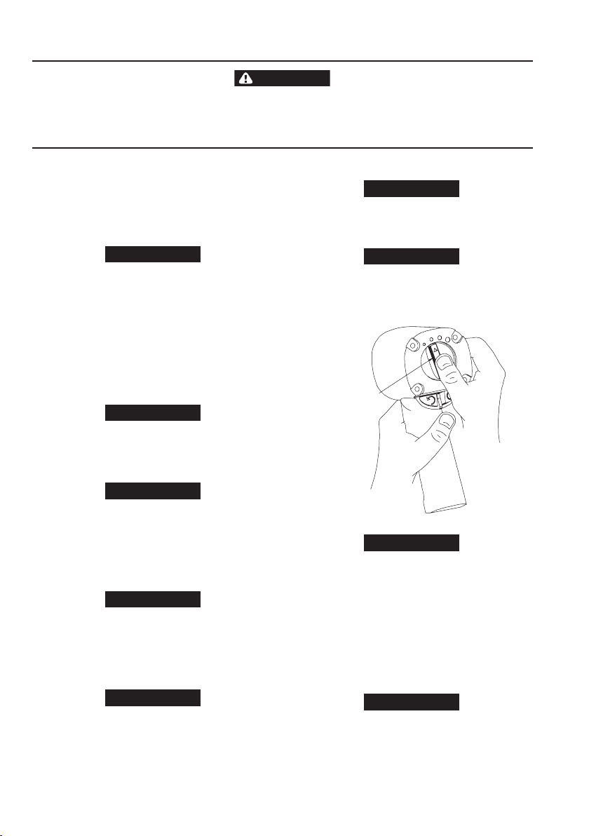
1. Remove the Motor Assembly from the Housing (19) by pushing
on Power Management Dial (35) from the back of the Housing.
Refer to Dwg. TPD1322.
(Dwg. TPD1322)
If the Motor Assembly cannot be removed from the Housing by
pushing, tap the Power Management Dial lightly until the Motor
Assembly is free.
2. Remove the Silencer (6A) from the top of the Cylinder (1). Remove
the Power Management Dial from the rear of the Cylinder (1).
Remove the Power Management Dial Seal (5A) if it needs to be
replaced.
3. Remove the Front End Plate (2) from the Cylinder by tapping the
splined end of the Rotor (5) with a plastic hammer. If the Front
End Plate does not come loose, secure a center punch in a vise
with the point angled downward and outward from the vise.
Grasp the Cylinder and Front End Plate in one hand and position
the hole in the end of the Rotor against the punch.
If you continue to rotate the Anvil, it will cam the Hammers out
of engagement. Don’t do this; merely rotate the Anvil until it
comes up solid.
3. Hold the Hammer Frame rmly and without disturbing the
hammers, gently lift the Anvil while simultaneously rotating it
clockwise about 1/8 of a turn, from the Hammer Frame.
Be careful not to drop the Cylinder since it can be damaged by
hitting a hard surface.
Using the other hand, tap the punch with a hammer while pressing
the Rotor against the punch. After a few taps, the Front End Plate will
slide o of the Cylinder.
Page 3
NOTICE
To prevent damage to the Cylinder, do not tap or strike Cylinder on
FRONT END PLATE
FRONT ROTOR BEARING
BENCH WITH NONMETALLIC SURFACE
CYLINDER
REAR ROTOR BEARING
BENCH WITH NONMETALLIC SURFACE
NOTICE
NOTICE
LEFT-HAND BUTTON
INLET BUSHING
INLET CLIP
REMOVAL TOOL
ASSEMBLY
TRIGGER
SLOT FOR TAB
(BOTH SIDES)
TAB ON INLET
RETAINER CLIP
(BOTH SIDES)
TILT VALVE STEM
HOOKED TOOL
NOTICE
NOTICE
a hard or metallic surface when removing the Rotor Bearings (3).
To remove the Front Rotor Bearing, hold the Front End Plate with
Front Rotor Bearing down and tap the Front End Plate on a at,
nonmetallic surface such as a work bench. This will loosen the Front
Rotor Bearing so that it will drop out of the Front End Plate. Refer to
Dwg. TPD1323.
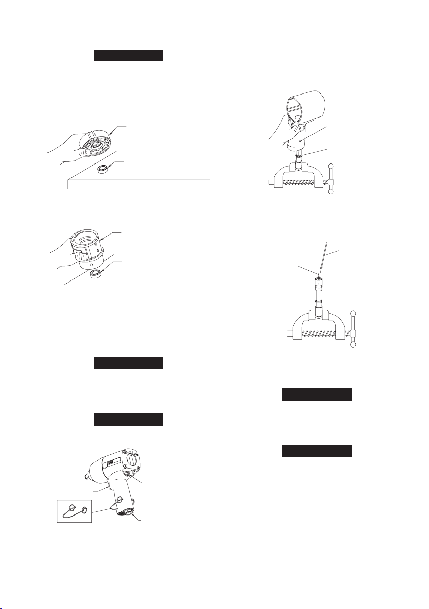
1. Secure the Inlet Bushing in a vise. Press in both tabs of the Inlet
Retainer Clip (27) and pull upward on the Housing (19). This
will allow the Inlet Bushing to come free from the Handle of the
Housing. Refer to Dwg. TPD1326.
2. Pull the Trigger (28) from the front of the Housing and remove
the Trigger O-ring (2A).
(Dwg. TPD1323)
4. Remove the Rear Rotor Bearing Retainer (6) from the rear of
the Rotor (5). The Rotor can now be removed from the Cylinder.
Remove the Vanes (4) from the Rotor if they need to be replaced.
(Dwg. TPD1324)
5. To remove the Rear Rotor Bearing, hold the Cylinder with the Rear
Rotor Bearing down and tap the Cylinder on a at, nonmetallic
surface such as a work bench. This will loosen the Rear Rotor
Bearing so that it will drop out of the Cylinder. Refer to Dwg.
TPD1324.
6. Working from the rear of the Housing, push out the Motor Gasket (7).
When removing the Motor Gasket, do not use a screwdriver or
any other sharp object which could damage the Gasket and/or
Housing.
Disassembly of the Throttle Mechanism
For ease of disassembly, we recommend using the Inlet Clip
Removal Tool (36). See Dwg. TPD1681.
(Dwg. TPD1681)
45481785_ed1 3
(Dwg. TPD1326)
3. With the Inlet Bushing still in the vise, remove the Tilt Valve Seat
Retainer (1G) and Tilt Valve Seat Support (1F). Use a hooked tool
with no sharp edges to remove the Tilt Valve Seat (1E) from the
Inlet Bushing. Refer to Dwg. TPD1327.
(Dwg. TPD1327)
4. Remove the Tilt Valve (1D) and Tilt Valve Spring (1C) if damaged.
5. Remove the Inlet Bushing Seal (1B) and Inlet Retainer Clip (27) if
damaged. Remove Washer (1A).
Do not remove the Inlet Bushing Screen (20A) from the Inlet
Bushing unless it is damaged. Clean the Inlet Bushing Screen by
using a suitable cleaning solution in a well ventilated area.
Disassembly of the Reverse Valve Mechanism
The Reverse Valve Assembly cannot be removed without rst
removing the Forward and Reverse Buttons (4A) and (4B).
Therefore, it is important that the procedure below be followed
exactly.
1. Notice the notches on either side of the partition. These notches
indicate the correct location for insertion of a thin-bladed
screwdriver used for removing the Forward and Reverse Buttons.
Insert the screwdriver between the partition and the Button
which is fully extended. Gently pry against the Button to
disengage the detent so that the Button can be removed. After
the Button is removed, reach inside the Housing and rotate the
Reverse Valve to extend the remaining Button. Repeat the above
procedure for the remaining Button. Refer to Dwg. TPD1328.
Page 4

4 45481785_ed1
REMOVAL OF
FORWARD/
REVERSE
BUTTONS
(Dwg. TPD1328)
REVERSE
VALVE
NOTICE
NOTICE
NOTICE
EARS
DOWEL
2. Insert thumb into the front of the Housing and push down on the
Reverse Valve so that it can be removed through the bottom of
the handle. Refer to Dwg. TPD1329.
Assembly
General Instructions
1. Whenever grasping a tool or part in a vise, always use leathercovered vise jaws to protect the surface of the part and help
prevent distortion. This is particularly true of threaded members
and housings.
Always use leather-covered vise jaws when clamping the handle
in a vise. Leather will conform to the shape of the handle and
allow the tool to be held securely. To prevent damage to the
exhaust diuser, never clamp only the bottom of the handle.
2. Always clean every part and wipe every part with a thin lm of oil
before installation.
Do not remove grease from the impact mechanism or Hammer
Case (15). If the impact mechanism has not been disassembled,
inject Ingersoll Rand No. 115-1LB Grease through the Hammer
Case Grease Fitting (17).
When disassembling and assembling the impact mechanism,
remove all grease from the impact mechanism and Hammer Case
and lubricate the impact mechanism and Hammer Case Bushing
(16) with Ingersoll Rand No. 105-1LB Grease or Ingersoll Rand
No. 105-8LB Grease.
3. Apply a lm of o-ring lubricant to all O-rings before nal
assembly.
Assembly of the Reverse Valve Mechanism
1. Install the Bottom Reverse Valve O-ring (3B) (color-coded blue)
and the Top Reverse Valve bring (3A) on the Reverse Valve (30).
2. Insert the Reverse Valve in the bottom of the handle making sure
that two ears on the Reverse Valve are facing downward. Refer to
Dwg. TPD1330.
(Dwg. TPD1329)
Do not try to remove the Reverse Valve by pushing upward. It
can only be removed by pushing it downward and out of the
bottom of the handle. If the Reverse Valve does not come free,
tap the bottom of the handle lightly with a rubber hammer until
it drops out.
3. Remove the Top Reverse Valve O-ring (3A) and the Bottom
Reverse Valve O-ring (3B) from the Reverse Valve.
(Dwg. TPD1330)
Use a wooden dowel to push the Reverse Valve up through
the handle until the top of the Reverse Valve is ush with or
slightly above the bottom of the motor bore in the Housing
(19). Refer to Dwg. TPD1331.
(Dwg. TPD1331)
Page 5

NOTICE
If the Reverse Valve is pushed up too far and becomes wedged,
FRONT OF
HOUSING
APPROX. 1/32”
REVERSE
VALVE
NOTICE
REVERSE
VALVE
FORWARD
BUTTON
REAR OF
HOUSING
TAB
REVERSE
VALVE
REVERSE
BUTTON
TAB
REAR OF
HOUSING
NOTICE
WARNING
WARNING
it will have to be pushed back down through the handle and
re-inserted from the bottom of the handle. The Reverse Valve
cannot be removed by pushing it up through the handle and
into the motor bore. If the Reverse Valve must be removed and
re-installed, make sure that the Top and Bottom Reverse Valve
O-rings have not been rolled o and are in their proper positions
on the Reverse Valve.
3. When the Reverse Valve has been installed, rotate the Reverse
Valve so that the tab on the Reverse Valve is at the rear of the
Housing. Refer to Dwg. TPD1332.
(Dwg. TPD1332)
If the orientation of the Reverse Valve is not correct (tab facing
the rear of the Housing), the Trigger (28) and the Forward and
Reverse Buttons (4A) and (4B) cannot be installed.
4. Install the Trigger O-ring (2A) on the Trigger. Insert the Trigger
Assembly in the front of the Housing.
5. Rotate the Reverse Valve in either direction until an ear comes up
against the Trigger.
6. Look through the Housing from the rear. If the tab on the Reverse
Valve has been rotated to the left, install the right Button in the
Housing. When one Button has been installed, push the Button
in. This will rotate the’ Reverse Valve so that the other Button can
be installed. Refer to Dwg. TPD1333.
(Dwg. TPD1334)
If the Forward/Reverse Buttons will not install easily, move the
Reverse Valve slightly higher in the handle to provide better
alignment with the Buttons.
7. After the Forward/Reverse Buttons have been installed, remove
the Trigger before proceeding with installation of the throttle
mechanism.
Assembly of Throttle Mechanism
1. Using an Inlet Bushing Screen Installation Tool, install the Inlet
Bushing Screen (20A), screened end rst, in the bottom (hex end)
of the Inlet Bushing (20). Insert the rounded end of the tool in the
cone formed by the screen and tap the end of the tool to secure
the rim of the screen in the Bushing. Refer to Dwg. TPD1473.
Inlet Bushing Screen Installation Tool
0
(Dwg. TPD1473)
2. Install the Washer (1A), Inlet Retainer Clip (27), Inlet Bushing Seal
(1B), Tilt Valve Spring (1C), Tilt Valve (1D) Tilt Valve Seat (1E) and
Tilt Valve Seat Support (1F).
The Tilt Valve Seat Retainer (1G) must be properly installed in the
groove in the Inlet Bushing (20). To check for correct installation
of the Retainer, insert a pin into one of the holes in the Retainer
and rotate the Retainer. A correctly installed Retainer will
(Dwg. TPD1333)
If the tab on the reverse Valve has been rotated to the right,
install the left Button. Refer to Dwg. TPD1334.
rotate freely but with some resistance in the groove of the Inlet
Bushing. An incorrectly installed Retainer will pop out of the
Inlet Bushing when the Retainer is rotated.
Do not use compressed air to check installation of the Tilt Valve
Seat Retainer or Inlet Bushing Screen unless the entire Inlet
Bushing Assembly is installed in the tool with the Hammer Case
installed and properly secured to the Motor Housing. Failure to
do so could result in injury.
Install the Tilt Valve Seat Retainer.
45481785_ed1 5
Page 6

6 45481785_ed1
NOTICE
When re-installing the Inlet Bushing Assembly (20), pull the
NOTICE
INSTALLATION
OF MOTOR
GASKET
NOTICE
TOP HAMMER
HALF--ROUND
NOTCH ON RIGHT
BOTTOM HAMMER
HALF--ROUND
NOTCH ON LEFT
NOTICE
Trigger (28) outward and make sure that the Reverse Button (4B)
is depressed before snapping the Inlet Bushing Assembly back
into the Housing.
3. Install the Inlet Bushing Assembly by pushing it into the hole in
the Housing until you see and hear the tabs on Inlet Retainer Clip
snap into place through the slots in Housing handle.
The Reverse Button (left) (4B) must be pushed in before the
Trigger can be installed. Otherwise, the Trigger will be damaged
during installation.
4. Install the Trigger by pushing it into the handle until a click is
heard indicating that it is properly engaged.
(Dwg. TPD1336)
Assembly of the Motor
When disassembling, assembling or pulling the Motor, we
recommend replacement of the Motor Gasket (7).
1. Install the Motor Gasket in the Housing making sure that the
grooves in the tab of the Motor Gasket t around ridge in the
Housing. Refer to Dwg. TPD1336.
2. Install the Rear Rotor Bearing (3) into the rear of the Cylinder (1).
3. Install the Rotor in the Cylinder and secure with the Rear Rotor
Bearing Retainer (6).
4. Install Vanes (4) in the slots in the Rotor (5).
5. Install the Front Rotor Bearing (3) into the Front End Plate (2).
Install the Front End Plate on the Cylinder by pressing on the
inner race of the front Rotor Bearing until the Bearing is seated on
the Rotor Shaft.
6. Install the Power Management Dial Seal (5A) on the Power
Management Dial (35) and install the Dial in the end of the
Cylinder.
7. Clean the Silencer (6A) using a suitable cleaning solution in a
well-ventilated area. Position the Silencer over the top of the
Cylinder and insert the Motor Assembly into the Housing (19),
Power Management Dial end rst.
Assembly of the Impact Mechanism
(Dwg. TPD1535)
1. Coat the Hammers (14) with a light lm of No. Ingersoll Rand
105-1LB Grease or Ingersoll Rand No. 105-8LB Grease.
2. Heavily coat the jaws of the Anvil (8) with Ingersoll Rand No.
105-1LB Grease or Ingersoll Rand No. 105-8LB Grease.
3. Replace the Hammers in the Hammer Frame (12) exactly as they
were when you marked them prior to disassembly.
If you are installing new Hammers or want to change the location
of the existing Hammers to utilize both impacting surfaces, slide
the Hammers in the Hammer Frame so that the half-round notch
on one Hammer is located on one side of the Frame and the
half-round notch on the other Hammer is located on the other
side of the Frame.
4. Replace the Hammer Pins (13).
5. Examine the base of the Anvil (8) and note its contour. While
looking down through the Hammer Frame, swing the top
Hammer to its full extreme one way or another until you can
match the contour of the Anvil. Enter the Anvil into the Hammer
Frame and through the rst Hammer. Swing the bottom Hammer
in the opposite direction from the top Hammer and maneuver
the Anvil slightly until it drops into the bottom Hammer. Refer to
Dwg. TPD1535.
Assembly of the Air Wrench
1. Position the Motor Housing (19) in leather-covered vise jaws with
the splined shaft of the Rotor in a horizontal position.
2. Place the assembled impact mechanism down onto the splined
hub of the Rotor.
3. Position the Hammer Case Gasket (18) against the face of the
Motor Housing.
Page 7

NOTICE
Be sure that the at on the bottom of the Hammer Case Gasket is
FRONT OF
HOUSING
GASKET
FLATS
installed in the corresponding at in the Housing. If the Hammer
Case Gasket is not installed correctly, the Air Wrench will not
function properly.
Refer to Dwg. TPD1335-1.
4. Apply a thin lm of Ingersoll Rand No. 105-1LB Grease or
Ingersoll Rand 105-8LB Grease on inside surface of the Hammer
Case Bushing (16), and place the Hammer Case (15) down over
the Anvil and against the Motor Housing.
(Dwg. TPD1335-1)
5. Install the Hammer Case Screws (11) and tighten them to 25 in-lb
(2.8 Nm) torque.
Troubleshooting Guide
Trouble Probable Cause Solution
Daily, inject 3 cc of Ingersoll Rand No. 50 Oil into the inlet and run the tool to
lubricate the motor.
Install proper air supply and connection. Refer to Dwg. 04581666 on Page 2 of Air
Impact Wrench Product Information Manual Form 04584686.
Using a clean, suitable, cleaning solution in a well ventilated area, clean the Inlet
Bushing Screen.
Examine Cylinder. Check outside and ends for wear or damage and inside for
scored or wavy bore. Replace Cylinder if any of these conditions exist. Replace
End Plates if they are scored.
Disassemble the Tool and clean in a clean, suitable, cleaning solution in a well
ventilated area. Assemble the Tool and inject 3 cc of the recommended oil into
Inlet and run Tool to lubricate internal parts.
Replace Reverse Valve. Refer to Assembly of the Reverse Valve Mechanism.
Refer to “Assembly of the Reverse Valve Mechanism”.
Disassemble motor and replace worn or broken parts and reassemble. Refer to
Assembly of the Motor.
Lubricate impact mechanism through Hammer Case Grease Fitting using the
recommended grease.
Remove Hammer Case Assembly and examine impact
mechanism parts. Replace any worn or broken parts.
Refer to Assembly of the Impact Mechanism.
Low power
Motor will not run
Tool will not impact
Dry Motor
Inadequate air supply
Dirty Inlet Bushing Screen
Worn or broken Vanes Replace a complete set of Vanes.
Worn or broken Cylinder
and/or scored End Plates
Dirty motor parts
Damaged Reverse Valve
Incorrect assembly of motor
Insucient lubricant in impact
mechanism
Broken or worn impact
mechanism parts
Impact mechanism not
assembled correctly
Related Documentation
For additional information refer to:
Air Impact Wrench Product Safety Information Manual Form 04580916.
Air Impact Wrench Product Information Manual Form 04584686.
Air Impact Wrench Parts List Manual Form 04584025.
Manuals can be downloaded from www.irtools.com.
45481785_ed1 7
Page 8

www.irtools.com
© 2007 Ingersoll Rand Company
 Loading...