

Page 1

Air Grinder, Die Grinders and Sanders CA Angle Series
Part s Information
16574014
Edition 1
June 2006
Save These Instructions
Page 2
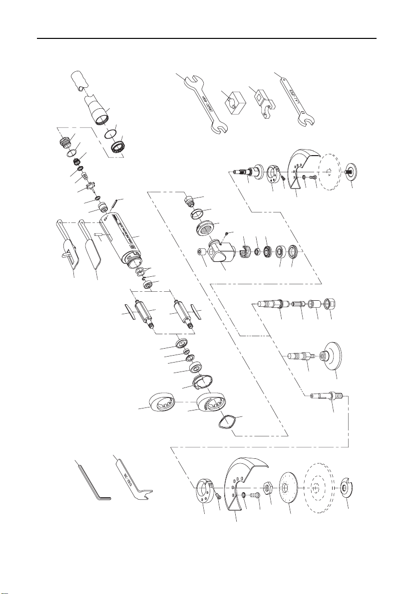
CA Angle Air Grinder, Die Grinder and Sander Exploded Diagram
46
31
28
21
27
ENDING IN G4,
G4C OR G4L
FOR MODELS
47
42
41
29
30
31
ENDING IN S4,
S4C OR S4L
36
37
35
32
33
31
39
34
43
44
46
52
1
3
4D
4C
4B
4A
4
6A
51
50
2
FOR MODELS
ENDING IN H63
H63C OR H63L
7
8
6
5
10
11
CA120
13
9
CA200
12
12
14
15
16
17
21
23
24
25
26
22
13
18
FOR MODELS
19A
48
49
19
41
20
36
42
35
FOR MODELS
ENDING IN P63,
P63C OR P63L
40
37
38
31
39
(Dwg. TPA1268-6)
2 16574014_ed1
Page 3

CA Angle Air Grinder, Die Grinder and Sander Parts List
Item Part Description Part Number Item Part Description Part
Common parts for ALL CA Grinders 22 Angle Housing Assembly LA1-A550S
1 Inlet Assembly LG1-A465A 23 Clamp Spacer LA1-46
2 Inlet Screen R1602-61 24 Clamp Nut LG1-27
• 3 Inlet Seal 85H-167 25 Grease Fitting D0F9-879
Throttle Valve Cartridge Kit LG1-K300 26 Upper Arbor Bearing AG210-693
4 Throttle Valve Cartridge Case LG1-300A ¤ 27 Wick
4A Throttle Val ve S eat LG1-303 for CA120 LA1-560
4B Throttle Val ve AG210-302 for CA200 LA1-561
4C Throttle Valve Spring 7L-51 28 Bevel Gear Nut AG210-578A
4D Throttle Valve Spring Seat LG1-592 29 Lower Arbor Bearing AG210-24
5 Motor Housing LG1-40 30 Arbor Bearing Cap AG210-531
6 Throttle Lever LG1-273 31 Arbor
6A Locking Throttle Lever Assembly
(for models ending in L, C, ML or MC)
* Lever Lock LG1-402 for all models ending in
* Lock Spring LG1-405
* Lock Pin 5UT-757 for all models ending in
7 Throttle Lever Pin 61H-120
8 Throttle Valve Plunger LG1-191 H63, H63C or H63L LA1-103-1
9 Rear Rotor Bearing DG230-22 * Warning Label
• 10 Rear Rotor Bearing Spacer (2) DG20-278 for models ending in P63-EU EU-63--99
• 11 Rear Rotor Bearing Retainer LG1-118 for all other models ending in-EU EU-99
12 Rotor for all other models LG1-99
for CA120 (5 vane slots) LG1-53-5 * Nameplate
• 13 Vane Packet (set of 5 Vanes) LG1-42-5 for all other CA120 models LA112-301
• 16 Front Seal Cup LG1-32 Additional parts for all collet
# 19A Low Profile Concentric Flange
* Not illustrated.
• To keep downtime to a minimum, it is desirable to have on hand certain repair parts. We recommend that you stock one
(pair or set) of each part indicated by a bullet (•) for every four tools in service.
¤ The LA1-A550S Angle Housing Assembly is furnished with two Wicks. Use Wick (LA1-561) with the notch on CA200 models.
for CA200 (3 vane slots) LG1-53-3 for CA120 models ending in-EU LA112-EU-301
14 Front End Plate LG1-11 for CA200 models ending in-EU LA120-EU-301
15 Front End Plate Spacer DG10-65-5 for all other CA200 models LA120- 301
17 Front Rotor Bearing LG1-24
18 Flow Ring 32 Collet
for CA120 (12000 rpm) (brown) LG1-103-1 for models ending in-EU DG110-700for CA200 (20000 rpm) (red) LG1-103-3 6mm
19 High Profile Flange LG1-23 for all other models DG110-700-
(for all models ending in C)
20 Flange Clamp LG1-29 34 Collet Nut AG210-699A
21 Bevel Pinion and Bevel Gear
(sold only as a matched set)
for CA120 LA1-A552-2.0S
for CA200 LA1-A552-1.5A
LG1-A400 for all models ending in
LG1R-23 G4
G4, G4C or G4L
S4, S4C or S4L
P63, P63C or P63L
models
33 Nosepiece AG210-698A
Number
AG210-4-G4
AG210-4-W2
LA1-6
WARNING
# Always install a Locking Throttle Lever Assembly (6A) on a tool with a Low Profile Concentric Flange (19A). Do not
equip a tool with a standard non-locking Throttle Lever (6) and Low Profile Concentric Flange. This can allow the tool to
continue to run if dropped or set down.
16574014_ed1 3
Page 4

Item Part Description Part Number Item Part Description Part
Additional parts for all
models ending in P63 or H63
35 Wheel Guard AG20-106-3 Ø Piped Away Exhaust Kit LG1-K284
36 Guard Lock Washer (3) R2-320 + 50 Exhaust Hose Adapter LG1-284
37 Guard Mounting Screws (3) LA1-667 + 51 Exhaust Hose Retainer LG1-67
38 Wheel Flange (for P63) R0A2D61-337 + 52 Exhaust Hose 3RL-284
39 Flange Nut * Bur Kit LG1-K1
for P63 AG21-337A-3 * 2” Abrasive Pad Kit LG1-K2
for H63 LA1-388 * 3” Abrasive Pad Kit
40 Flange Spacer (for P63) LA2-111
41 Guard Adapter Assembly LA1-A710 * Shroud Kit (for collet models only) LA1-K980
42 Guard Pinch Bolt 804-634 * No. 10 Oil (4 oz. bottle) 10Z4
Additional parts for
all models ending in S4
43 Sanding Pad
(standard on models ending
in S4M, S4MC or S4ML; optional on
models ending in S4, S4C or S4L)
for CA120 (3” diameter) 3-PAD
for CA200 (2” diameter) 2-PAD
Accessories for CA models
44 Collet Body Wrench/Collet Nut Wrench
(7/16” x 11/16” ) (included with all
models ending in G4, G4C or G4L)
46 Arbor Bearing Cap Wrench
47 Clamp Nut Wrench
48 Arbor Wrench (3/16” hex)
49 Wheel Nut Wrench (included with all
* Not illustrated.
Ø When ordering a Piped-Away Ex haust Kit, make certain the wrench hex on the Inlet Assembly of your tool is threaded. If it is
NOT threaded, order a new Inlet Assembly (Part No. LG1-A465A).
+ Standard equipment on models ending in M, MC or ML and ALL Front Exhaust models; optio nal equipment on all other models.
for models ending in S4, S4C
or S4L
for models ending in H63 LA1-29
(included with all models)
(included with all
models ending in P63, P63C or P 63L)
models ending in P63, P63C or P 63L)
DG20-69A
AG210-29
LA2-253
AG220-340
D32-26
* Variable Speed Control Assembly
(with piped away exhaust)
(for CA120 models only)
* No. 63 Oil (4 oz. bottle) 63Z4
* No. 67 Grease (1 lb. can) 67-1LB
* No. 77 Grease (1 lb. can) 77-1LB
* Shroud Kit (for non- col let mo del s) LA1-K975
Number
LG1-A1015
LG1-K3
Parts and Maintenance
When the life of the tool has expired, it is recommended that the tool be disassembled, degreased and parts be separated by
material so that they can be recycled.
Tool repair and maintenance should only be carried out by an authorized Service Center.
Refer all communications to the nearest Ingersoll Rand Office or Distributor.
Related Documentation
For additional information refer to:
Product Safety Information Manuals 04584959, 04580387 and 04580288.
Product Information Manuals 16576282, 16576308 and 80221096.
Product Maintenance Information Manual 16575060.
Manuals can be downloaded from www.irtools.com.
4 16574014_ed1
Page 5

Notes
16574014_ed1 5
Page 6

Notes
6 16574014_ed1
Page 7

Notes
16574014_ed1 7
Page 8

www.irtools.com
© 2006 Ingersoll Rand Company
 Loading...