

Ingersoll-Rand 150-8000 Operator's Manual
October
HB Series Desiccant Dryer
I-R ORDER NUMBER: 81696181
CUSTOMER NAME: Woodward RCC c/o ALL Equipment
CUSTOMER CONTACT: Kerry Fang- 704-655-5364
CUSTOMER P.O. NUMBER: 78608
DRYER MODEL: HB3000 EMS
120.26 Dryer - Operation, Installation, Maintenance Manual, and Parts
Models 150-8000
Operator’s Manual
EN
Operator’s Manual
ES
Manual Del Operador
FR
Manuel De L’opérateur
PT
Manual do Operador
80442858
Revision E
2012
Save These Instructions

I-R ORDER NUMBER: 81696181
CUSTOMER NAME: Woodward RCC c/o ALL Equipment
CUSTOMER CONTACT: Kerry Fang- 704-655-5364
CUSTOMER P.O. NUMBER: 78608
DRYER MODEL: HB3000 EMS
120.26 Dryer - Operation, Installation, Maintenance Manual, and Parts

1
HB Series Desiccant Dryer Models 150-8000
ingersollrandproducts.com
CONTENTS
120.26 Dryer - Operation, Installation, Maintenance Manual, and Parts
CONTENTS PAGE
1.0 CONTENTS 1
2.0 INTRODUCTION 2
3.0 WARRANTY 2
4.0 HEAT REACTIVATED DRYER
NOMENCLATURE 2
5.0 RECEIVING AND INSPECTION 3
5.1 INSPECTIONS
5.2 UNPACKING AND HANDLING
6.0 SAFETY AND OPERATION
PRECAUTIONS 3
7.0 PRINCIPLES OF OPERATION 4
7.1 INTRODUCTION
7.2 DRYING CYCLE
7.3 REGENERATION CYCLE
7.3.1 BLOWER PURGE REGENERATION
7.3.2 BLOWER PURGE REGENERATION
WITH SELECTABLE COOL SWEEP
7.3.3 HEATLESS PRESSURE SWING
REGENERATION
7.4 TOWER REPRESSURIZATION
7.4.1 BLOWER PURGE
REPRESSURIZATION
7.4.2 BLOWER PURGE
REPRESSURIZATION WITH
SELECTABLE COOL SWEEP
7.4.3 HEATLESS PRESSURE SWING
REPRESSURIZATION
7.5 VALVES
7.6 CONTROLS
7.6.1 MICROPROCESSOR CONTROL
USER INTERFACE
7.6.2 STATUS PANEL USER INTERFACE
7.6.3 MICROPROCESSOR CONTROL
DISPLAY PARAMETERS
7.7 TIMING SEQUENCE
7.7.1 BLOWER PURGE TIMER CYCLE
7.7.2 BLOWER PURGE TIMER CYCLE
WITH SELECTABLE COOL SWEEP
7.7.3 HEATLESS PRESSURE SWING
TIMER CYCLE
7.8 RESTART MODES
7.8.1 MANUAL MODE (ZERO)
7.8.2 AUTO RESTART MODE (LAST)
7.9 OPERATING TIMES
8.0 ALARMS AND INDICATORS 8
8.1 MOISTURE INDICATOR
(STANDARD)
8.2 HEATER HIGH TEMPERATURE
ALARM WITH INTERLOCK
(STANDARD)
8.3 HEATER FAILURE ALARM
(STANDARD)
8.4 FAILURE TO SHIFT ALARM
(STANDARD)
8.4.1 FAILURE TO REPRESSURIZE
8.4.2 FAILURE TO DEPRESSURIZE
CONTENTS PAGE
8.5 HIGH DEW POINT ALARM
(INCLUDED WITH EMS)
8.6 ENERGY MANAGEMENT
SYSTEM (EMS) (OPTIONAL)
8.7 ALARM LIST
8.8 HIGH OUTLET TEMPERATURE
(OPTIONAL)
9.0 TECHNICIAN MODE 10
9.1 ENTERING TECHNICIAN MODE
9.2 OPERATING MODE
9.3 COOL SWEEP
9.4 HEATER TEMPERATURE SETPOINT
(BLOWER PURGE MODE ONLY)
9.5 ENERGY MANAGEMENT
SYSTEM (OPTIONAL)
9.5.1 ENABLING / DISABLING ENERGY
MANAGEMENT SYSTEM
9.5.2 SETPOINT ADJUSTMENT
9.6 PURGE TEMPERATURE (INCLUDED
WITH OPTIONAL EMS MODE)
9.7 RESTART MODE
9.8 EXTENDED HEATING (OPTIONAL,
BLOWER PURGE MODE)
9.9 HIGH DEW POINT ALARM (OPTIONAL)
9.9.1 DESCRIPTION AND ACTIVATION
9.9.2 SETPOINT ADJUSTMENT
9.10 PROGRAM JOG
9.11 SHUTDOWN SEQUENCE
10.0 INSTALLATION AND
INITIAL START-UP 14
10.1 EQUIPMENT APPLICATION
GUIDELINES
10.2 LOCATING AND MOUNTING
10.3 PIPING
10.4 FILTRATION
10.5 DEW POINT TRANSMITTER INSTALLATION
(OPTIONAL)
10.6 ELECTRICAL CONNECTION
10.7 START-UP
10.8 SHUT DOWN PROCEDURES
11.0 MAINTENANCE AND
SYSTEM CHECK 17
11.1 SCHEDULED MAINTENANCE
11.2 PRE-FILTERS AND POST-FILTERS
11.2.1 THREADED FILTERS
11.2.2 FLANGED FILTERS
11.3 MUFFLER CHANGE-OUT
PROCEDURE
11.4 NO-LOSS DRAIN VALVES
11.5 PILOT OPERATED ACTUATOR
11.6 DESICCANT CHANGEOUT
PROCEDURE
12.0 TROUBLESHOOTING 20
13.0 GENERAL ARRANGEMENT 21
14.0 WIRING DIAGRAM 36
15.0 FLOW DIAGRAM 42
16.0 REPLACEMENT PARTS 46
17.0 ENGINEERING SPECIFICATIONS 49

The Ingersoll Rand Blower Purge Desiccant Dryers are designed to
adsorb moisture from compressed air. The dryers are constructed with
two towers, each containing desiccant beads, that alternate between online (drying) and offline (regenerating) modes, yielding a continuous
stream of dry air at the dryer's outlet.
During normal operation, wet air passes through the on-line tower and
water vapor from the air is adsorbed (collected) on the desiccant beads.
While air is being adsorbed in the on-line tower, the moisture on the
desiccant in the offline tower is removed by a process called desorption
(regeneration). In standard blower purge operation, after an initial rapid
depressurization, air from a blower on the dryer skid passes through a
2
HB Series Desiccant Dryer Models 150-8000
ingersollrandproducts.com
heater and over the desiccant bed and carries the moisture off the bed
and out the dryer's exhaust. With the dryer's Bi-Mode feature, the
dryers may also be operated in a Heatless mode, which uses dry
compressed air as the purge air source but does not require use of the
heater or blower.
The continuous, alternating process of adsorption and desorption is
controlled using a customized Programmable Logic Controller that
switches the towers in a specific timed sequence. Very dry compressed
air dew points are achieved through the continuous switching and
operation of this dryer.
The Company warrants that the equipment manufactured by it and
delivered hereunder will be free of defects in material and workmanship
for a period of twelve months from the date of placing the Equipment in
operation or eighteen months from the date of shipment from the factory,
whichever shall first occur. The Purchaser shall be obligated to promptly
report any failure to conform to this warranty, in writing to the Company
in said period, whereupon the Company shall, at its option, correct such
nonconformity, by suitable repair to such equipment or, furnish a
replacement part F.O.B. point of shipment, provided the Purchaser has
stored, installed, maintained and operated such Equipment in
accordance with good industry practices and has complied with specific
recommendations of the Company. Accessories or equipment furnished
by the Company, but manufactured by others, shall carry whatever
warranty the manufacturers have conveyed to the Company and which
can be passed on to the Purchaser. The Company shall not be liable for
any repairs, replacements, or adjustments to the Equipment or any costs
of labor performed by the Purchaser or others without Company's prior
written approval.
The effects of corrosion, erosion and normal wear and tear are
specifically excluded. Performance warranties are limited to those
specifically stated within the Company's proposal. Unless responsibility
for meeting such performance warranties are limited to specified tests,
the Company's obligation shall be to correct in the manner and for the
period of time provided above.
THE COMPANY MAKES NO OTHER WARRANTY OR
REPRESENTATION OF ANY KIND WHATSOEVER, EXPRESSED OR
IMPLIED, EXCEPT THAT OF TITLE, AND ALL IMPLIED WARRANTIES
OF MERCHANTABILITY AND FITNESS FOR A PARTICULAR
PURPOSE, ARE HERBY DISCLAIMED.
Correction by the Company of nonconformities whether patent or latent,
in the manner and for the period of time provided above, shall constitute
fulfillment of all liabilities of the Company for such nonconformities
whether based on contract, warranty negligence, indemnity, strict liability
or otherwise with respect to or arising out of such Equipment.
The Purchaser shall not operate Equipment which is considered to be
defective, without first notifying the Company in writing of its intention to
do so. Any such use of Equipment will be at Purchaser's sole risk and
liability.
Note that this is Ingersoll Rand standard warranty. Any warranty in force
at the time of purchase of the equipment or negotiated as part of the
purchase order may take precedence over this warranty.
2.0 INTRODUCTION
3.0 WARRANTY
4.0 HEAT REACTIVATED DRYER NOMENCLATURE
NOMINAL*
FLOW POWER / NEMA/ ELECTRICAL ELECTRICAL MECHANICAL
PREFIX (SCFM) DEW POINT MAWP OPTION OPTION OPTION FILTERS
HB 150-8000 4 = 460-3-60 / -40 H = NEMA 4 / 0 = Standard 0 = Standard 0 = Standard A = Filters Attached
6 = 575/3/60 / -40 150 psig MAWP N = EMS L = Filters Loose
* Nominal Flows indicated are for 100°F inlet temperature, 100°F ambient temperature and 100 psig compressed air pressure.
120.26 Dryer - Operation, Installation, Maintenance Manual, and Parts
3
HB Series Desiccant Dryer Models 150-8000
ingersollrandproducts.com
5.1 INSPECTION
Upon receiving your Ingersoll Rand air dryer, please inspect the unit
closely. If rough handling has been detected, please note it on your
delivery receipt, especially if the dryer will not be immediately uncrated.
Obtaining the delivery person's signed agreement to any noted
damages will facilitate any insurance claims
5.2 UNPACKING AND HANDLING
A
WARNING
Under no circumstances should any person attempt to lift heavy
objects without proper lifting equipment (i.e., crane, hoist, slings or fork
truck). Lifting any unit without proper lifting equipment, can cause
serious injury.
5.0 RECEIVING AND INSPECTION
Refer to the General Arrangement drawing for the appropriate means for
lifting or moving the dryer. When lifting the dryer, ensure that no stress
is applied to the piping or valving. Refer to Section 10.2 for locating and
mounting of dryer.
6.0 SAFETY AND OPERATION PRECAUTIONS
Because an air dryer is pressurized and contains rotating parts, the
same precautions should be observed as with any piece of machinery
of this type where carelessness in operation or maintenance could be
hazardous to personnel. In addition to obvious safety rules that should
be followed with this type of machinery, safety precautions as listed
below must be observed:
1. Only qualified personnel shall be permitted to adjust, perform
maintenance or repair this air dryer.
2. Read all instructions completely before operating unit.
3. Pull main electrical disconnect switch and disconnect any separate
control lines, if used, before attempting to work or perform maintenance
on the unit.
4. Do not attempt to service any part while machine is in an operational
mode.
5. Do not attempt to remove any parts without first relieving the entire air
system of pressure.
6. Do not operate the dryer at pressures in excess of its rating.
7. Do not operate the dryer without guards, shields and screen in place.
8. Inspect unit daily to observe and correct any unsafe operating conditions.
OSHA
Heading Descriptions
A
WARNING
“Warning” is used to indicate a hazardous situation which has some
probability of death or severe injury. Warning should not be considered
for property damage accidents unless personal injury risk is present.
A
CAUTION
“Caution” is used to indicate a hazardous situation which may result in
minor or moderate injury.
A
NOTICE
“Notice” is used to indicate a statement of company policy as the
message relates directly or indirectly to the safety of personnel or
protection of property. Notice should not be associated directly with a
hazard or hazardous situation and must not be used in place of
“Danger,” “Warning,” or “Caution.”
A
NOTICE
The user of any air dryer manufactured by Ingersoll Rand, is hereby
warned that failure to follow the above Safety and Operation
Precautions may result in personal injury or equipment damage.
However, Ingersoll Rand does not state as fact, nor does it mean to
imply, that the preceding list of Safety and Operating Precautions is all
inclusive, and further, that the observance of this list will prevent all
personal injury or equipment damage.
120.26 Dryer - Operation, Installation, Maintenance Manual, and Parts
HB Series Desiccant Dryer Models 150-8000
ingersollrandproducts.com
4
7.1 INTRODUCTION
As described in Section 2, water vapor is removed from compressed air
by diverting air flow alternately between two towers filled with activated
alumina desiccant. While one tower processes the compressed air
stream adsorbing water vapor, the opposite tower regenerates by
desorbing the water vapor and venting it to atmosphere.
The Microprocessor Controller provides the ability to select between
blower purge or heatless regeneration. Both blower purge and heatless
regeneration methods are described in the following sections.
A
NOTICE
The Microprocessor Controller must be in the OFF position prior to
changing the mode (blower / heatless) of the dryer. After the change
is made and the Microprocessor Control is subsequently turned ON,
the dryer will be in the new mode of operation.
7.2 DRYING CYCLE
Saturated compressed air enters the dryer and is diverted to the
appropriate tower by the Inlet Flow Valves. (Refer to the Process and
Instrumentation Diagram.) The Right Tower Flow Valve is actuated to a
closed position to prevent air flow from entering the regenerating tower.
Simultaneously, the Left Tower Flow Valve is actuated to an open
position allowing air flow to the drying tower. During this time, the Left
Tower Purge Valve is actuated to a closed position, preventing the
compressed air from venting to atmosphere. As the compressed air
flows through the desiccant material in the left tower at pressure,
removal of water vapor from the air stream begins to occur through
adsorption. In the adsorption process, the desiccant material draws
water vapor out of the compressed air and "holds" it until the left tower
drying cycle is complete. Compressed air flows out of the tower for
delivery to the process use. The Outlet Flow Check Valves provide air
flow diversion to the outlet air connection of the dryer.
7.3 REGENERATION CYCLE
Previously adsorbed moisture removed from the process stream gets
stripped or desorbed from the desiccant material in the regeneration
process. The first stage of regeneration is tower de-pressurization.
After the Inlet Flow Valves are switched to divert air flow away from the
regenerating tower, the Depressurization Valve opens and the tower will
be depressurized. Through depressurization, a significant portion of the
previously adsorbed water vapor is stripped off of the desiccant material
and exhausted to atmosphere.
A
CAUTION
Any time the dryer is switched between two operating modes, care
must be taken to ensure the purge adjustment valve is adjusted
correctly. Refer to the specification sheet in this manual for proper
gauge setting.
7.3.1 BLOWER PURGE REGENERATION
In the blower mode, there is no dry compressed air used for
regeneration. Ambient air is drawn into the blower intake and
then discharged through the purge heater and through the
regenerating tower. After tower depressurization, the heater
and blower operate for 3 hours, 44 minutes. The blower
continues to operate for ten minutes to cool the heater
element.
7.3.2 BLOWER PURGE REGENERATION WITH SELECTABLE
COOL SWEEP
With the Cool Sweep feature, which uses a portion of dried
compressed air to cool the bed at the end of the regeneration
cycle, the heater and blower operate for 2 hours and 57
minutes. The blower continues to operate for an additional ten
minutes to cool the heater. The Repressurization Valve is then
opened, allowing dry compressed air to pass through the
regenerating tower for 48 minutes.
7.0 PRINCIPLES OF OPERATION
7.3.3 HEATLESS PRESSURE SWING REGENERATION
In the heatless mode, following depressurization,
regeneration uses approximately 15% of the dry compressed
air, expanded to atmospheric pressure to complete the
desorption process. As shown on the P & ID, the compressed
air exits the drying tower and a portion of the air flows through
the Purge Adjustment Valve and the Purge Orifice. Once the
air has passed through the Purge Orifice, it expands to
atmospheric pressure and continues the regeneration
process. Desorption occurs as the desiccant releases water
vapor into the regeneration air and is exhausted through the
Purge Valves. Note that in the Heatless Pressure Swing
Mode, proper setting of the purge flow is necessary to achieve
optimum dryer performance. Setting the purge flow too high
will waste compressed air and if set too low, the dryer will not
achieve dew point performance. The purge adjustment
manifold consists of the purge adjustment valve, purge
pressure gauge, and the purge orifice. Manually adjust the
purge adjustment valve until the reading on purge pressure
gauge matches the purge pressure setting listed on the tag
attached to the gauge.
A
NOTICE
When operating dryer in standard Blower Purge mode, dryer may
exhibit high discharge temperatures at tower switchover (300 °F) and
dew point spikes (+20°F). This is considered normal operation for this
equipment. Operator must insure that equipment located downstream
of dryer be capable of tolerating these conditions.
7.4 TOWER REPRESSURIZATION
Upon completion of tower regeneration, and prior to changing the Inlet
Flow Valve position to switch towers, the regenerated tower must be
repressurized.
A
NOTICE
Failure to repressurize prior to tower switchover will result in shocking
the desiccant material and cause premature desiccant dusting.
7.4.1 BLOWER PURGE REPRESSURIZATION
Three minutes prior to tower switch-over, the blower will be
shut off and the Purge Valves and Depressurization Valves
will close. The Repressurization Valve will then open,
allowing air from the outlet of the dryer to pressurize the tower
prior to switch-over. During normal tower regeneration, the
Repressurization Valve is closed, so that the blower supplies
the only source of regeneration air.
7.4.2 BLOWER PURGE REPRESSURIZATION WITH
SELECTABLE COOL SWEEP
Three minutes prior to tower switch-over, the Purge Valves
and Depressurization Valves will close. The Repressurization
Valve will then open, allowing air from the outlet of the dryer
to pressurize the tower prior to switch-over.
7.4.3 HEATLESS PRESSURE SWING REPRESSURIZATION
45 seconds prior to tower switch-over, repressurization is
accomplished by closing the appropriate Purge Valve and the
Depressurization Valve. When the Purge Valve closes, the
regeneration air begins to pressurize the tower. In addition,
the Repressurization Valve opens, allowing additional air from
the outlet of the dryer to assist the purge air and to ensure
adequate pressurization. During normal tower regeneration,
is held closed so that the only source of air for regeneration
passes through the purge adjustment assembly.
120.26 Dryer - Operation, Installation, Maintenance Manual, and Parts
5
HB Series Desiccant Dryer Models 150-8000
ingersollrandproducts.com
7.0 PRINCIPLES OF OPERATION
7.5 VALVES
Actuated valves are two-way valves that are switched using double
acting actuators. Each valve is actuated by a four-way solenoid valve
as shown on the P & ID.
A
NOTICE
Actuated valves require 75 psi min. pressure for proper operation.
The Inlet Flow Valves are connected as normally open valves. When
the dryer is de-energized, the solenoid valves for these valves supply air
to the "open" port on the appropriate valve actuator.
Purge Valves are connected as Normally Closed valves. When the
dryer is de-energized, the solenoid valves for these valves supply air to
the "closed" port on the appropriate valve actuator.
Outlet Check Valves, as well as Purge Check Valves, are single
direction check valves that will allow flow in the direction shown on the
P&ID but not allow flow in the opposite direction. Valve positions must
be changed accordingly for the appropriate mode selected.
7.6 CONTROLS
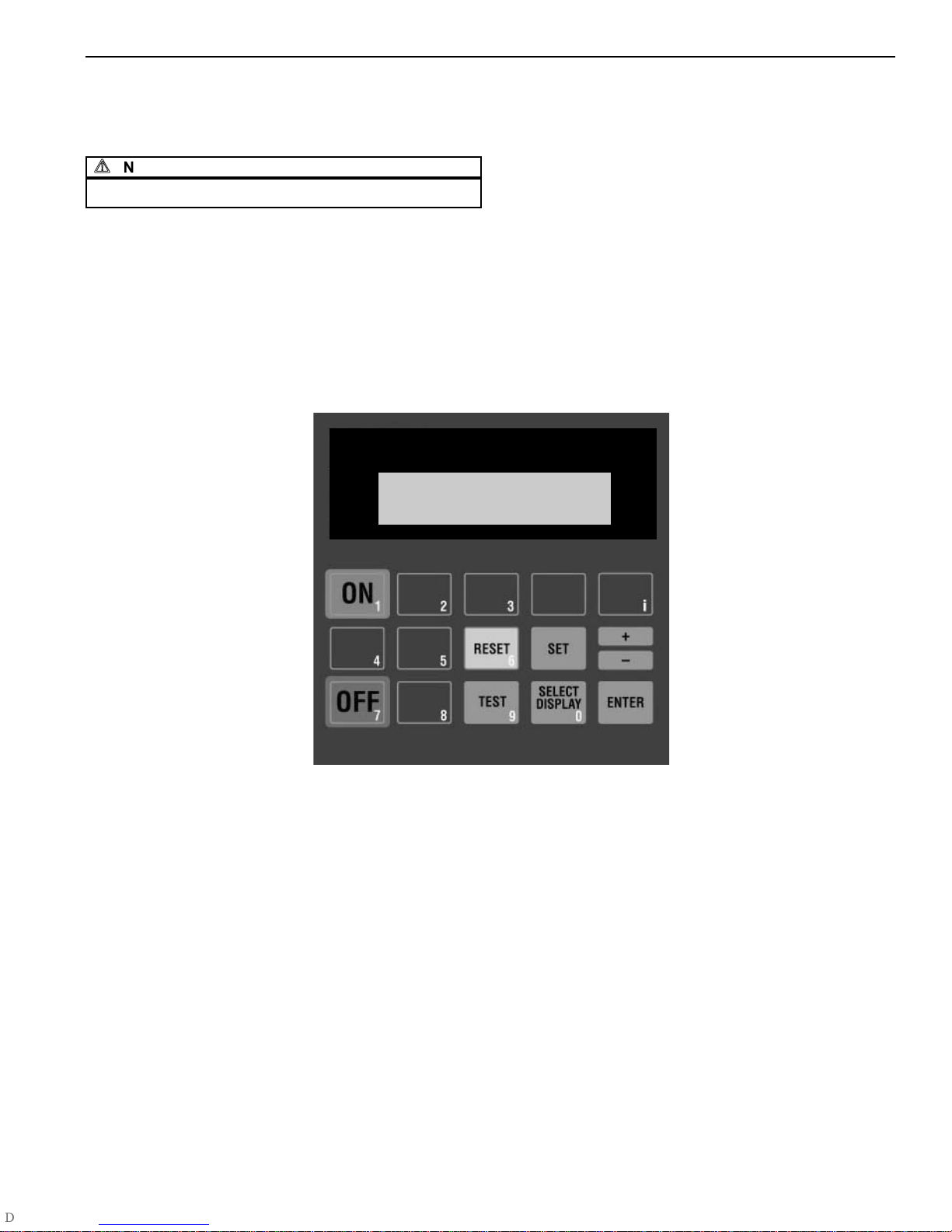
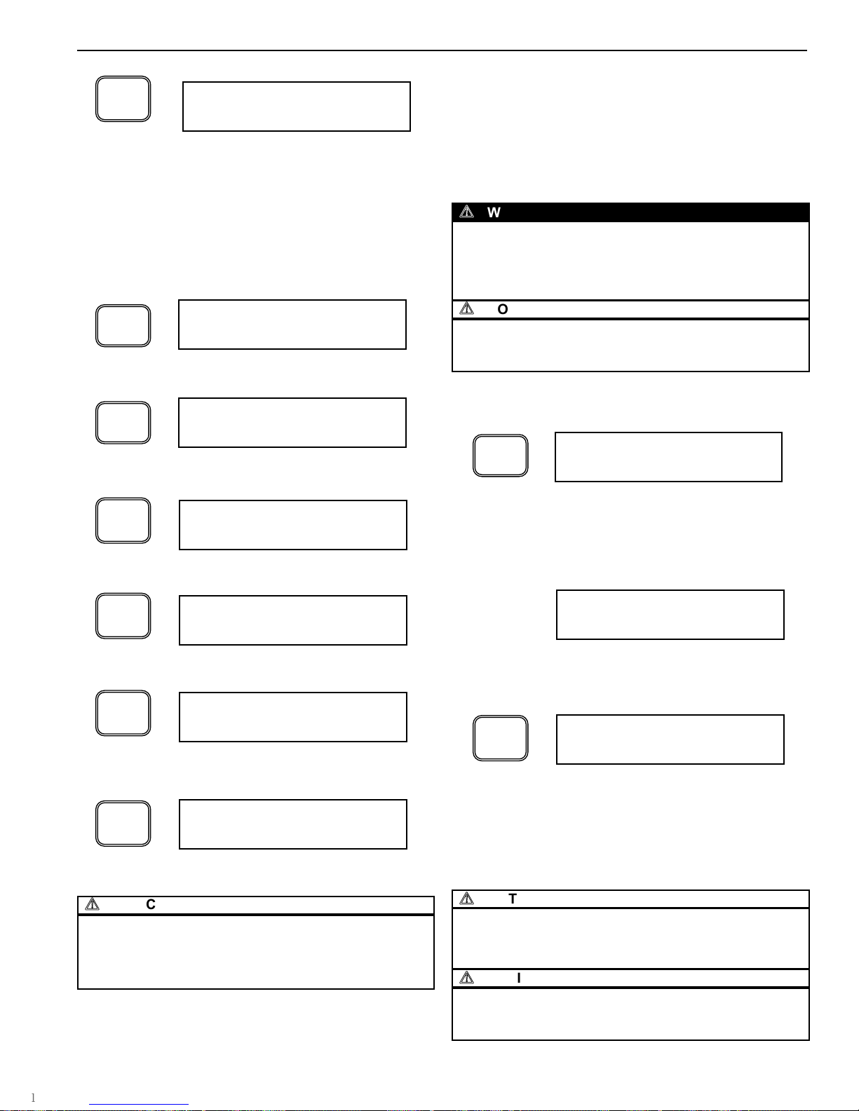
7.6.1 MICROPROCESSOR CONTROL USER INTERFACE
The Microprocessor Control display provides the user with the
operating parameters and their corresponding values. When
power is supplied to the dryer, the Microprocessor Control will
illuminate and default to the "Standby" mode, displaying the
"Press ON" prompt.
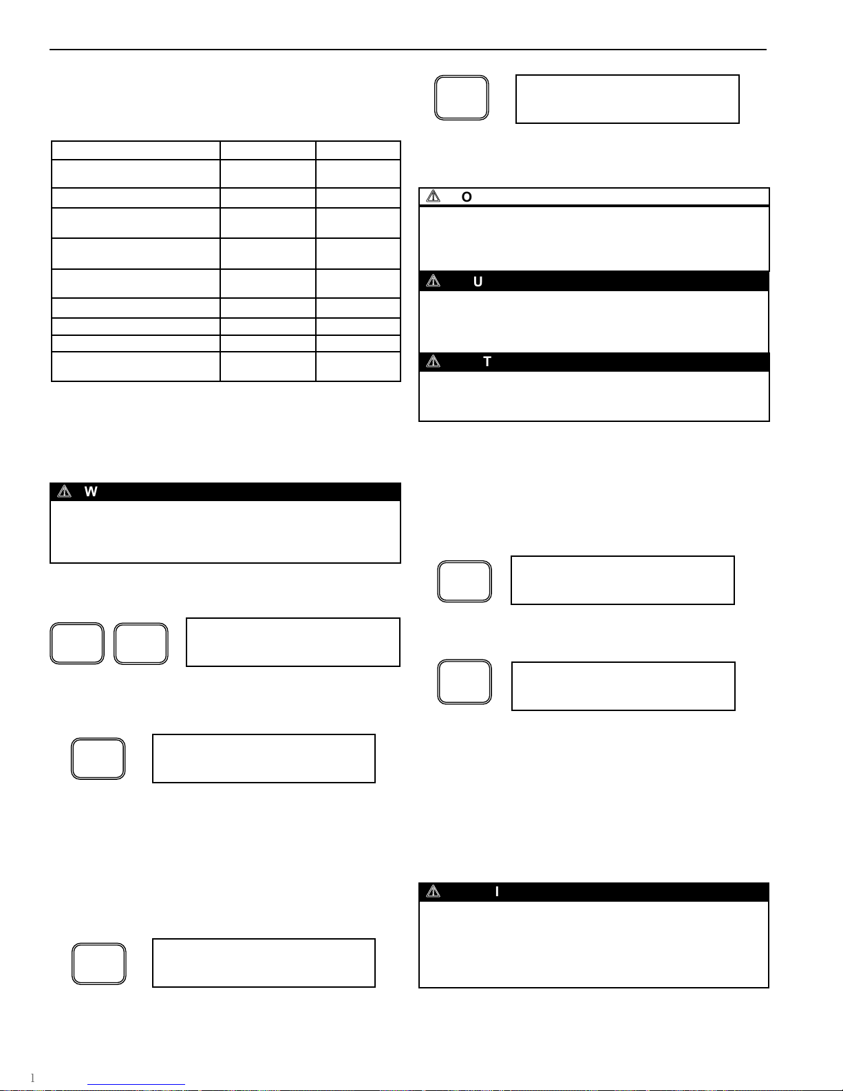
The following illustration summarizes the keypad functions.
Figure 1 - Microprocessor Controller
BUTTONS
• ON
Initiates PLC program. Begins system monitoring and valve
switching functions.
• OFF
Stops PLC program. Stops valve switching functions. Initiates
Shutdown Sequence. Opens Inlet Flow Valves. Closes Purge
Valves.
• SELECT DISPLAY
Allows the user to scroll through the available displays. The last
display selected will remain displayed as the default display.
• + / -
Allows user to increase set point values. Set point values cycle
through a fixed range. Also allows entering negative numbers in
Technician Mode.
•
Allows user to step backwards to the previous level of the menu.
• RESET
Pressing once clears the local alarm indication and de-energizes
the remote alarm contact for many alarm conditions. Should the
alarm condition persist, the alarm will return after the alarm inhibit
time has expired.
• SET
Permits the adjustment of parameters in TECHNICIAN MODE.
• ENTER
Used to accept changed parameters and set point values.
• TEST
Not used in Desiccant Dryer applications
• i
Restricted Level access for factory use only.
PRESS ON
120.26 Dryer - Operation, Installation, Maintenance Manual, and Parts
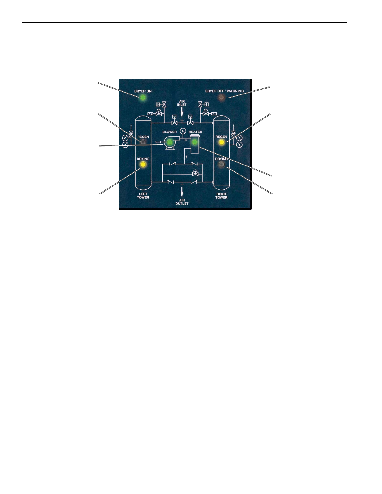
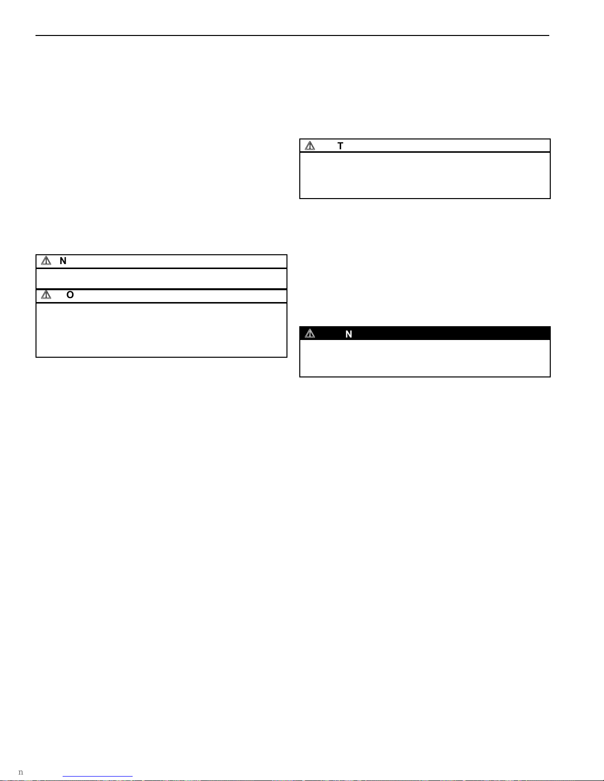
7.6.2 STATUS PANEL USER INTERFACE
The status panel provides clear indication of dryer status via
bright LED indicators. The following illustration summarizes
the panel’s features:
6
HB Series Desiccant Dryer Models 150-8000
ingersollrandproducts.com
7.0 PRINCIPLES OF OPERATION
Dryer ON (Green)
Left Tower Regeneration
(Yellow)
Left Tower Drying
(Yellow)
Dryer OFF / Alarm
(Red)
Right Tower Regeneration
(Yellow)
Right Tower Drying
(Yellow)
Figure 2 - Status Panel
Heater Operation
(Green)
Blower Operation
(Green)
NOTE: Ingersoll Rand solid state temperature controller modulates the
heater repeatedly during the heating cycle. Pulsating of the heater LED
will occur as a result and should be considered normal dryer operation.
7.6.3 MICROPROCESSOR CONTROL DISPLAY PARAMETERS
The Microprocessor Controller is capable of displaying a
number of system parameters in the default CUSTOMER
MODE. The following summarizes the parameters that can be
accessed by depressing the SELECT DISPLAY button from
the Microprocessor Controller. (Note that some displays are
optional and may not appear on all models):
• Tower Status {LT DRY / RT REGEN or LT REGEN / RT
DRY}: Provides visual confirmation of tower drying and
regenerating status.
• Step Timer {ie STEP 4 TIME 120}: Information screen
displaying the current step in the program and the time
remaining for the displayed step.
• Dew Point Temperature (OPTIONAL) - {DEW POINT TEMP:
XX}: When equipped with the optional EMS feature, provides
accurate display of dryer outlet pressure dew point.
• Purge Status (OPTIONAL) - {PURGE / NO PURGE}:
Indicates whether unit is currently consuming purging air.
Requires EMS.
• Heater Status (BLOWER PURGE MODE ONLY) - {On / Off}:
Indicates that the heater is being given a signal to heat the
purge air.
• Blower Status (BLOWER PURGE MODE ONLY) - {On / Off}:
Indicates that the blower is being given a signal to supply the
purge air.
• Heater Temperature (BLOWER PURGE MODE ONLY) {HEATER TEMP: XX}: Indicates the heater temperature set
point.
• Alarms {ALARM LIST - PRESS ENTER}: Depressing
<ENT> at this prompt permits viewing of current alarm status
and alarm history, which includes the time and date of the
alarm occurrence.
• Operating & Purge Times - {OPERATING TIMES - PRESS
ENTER}: Depressing <ENT> at this prompt provides access
to the operating and purge hours of operation.
• Operating Mode {OPERATING MODE: HEATLESS /
BLOWER PURGE}: HB dryers are capable of operating in
Blower Purge and Heatless Pressure Swing modes. This
display indicates mode of operation for dryer.
Once the last screen is displayed, depressing the SELECT DISPLAY
button will return the display to the top of the list.
7.7 TIMING SEQUENCE
All timing functions are performed by Ingersoll Rand’s Microprocessor
Controller, an advanced micro PLC designed exclusively for Ingersoll
Rand dryers. The Microprocessor Controller is completely programmed
at the factory and does not require any further adjustment. The standard
timing cycle switches the Inlet Flow Valves, which alternates the drying
tower. At the same time as the Inlet Flow Valve opens, the appropriate
tower Purge Valve opens to begin the purge flow generation. Once the
purge regeneration flow portion of the dryer cycle is complete, tower
repressurization begins as previously described.
120.26 Dryer - Operation, Installation, Maintenance Manual, and Parts

7
HB Series Desiccant Dryer Models 150-8000
ingersollrandproducts.com
7.0 PRINCIPLES OF OPERATION
7.7.1 BLOWER PURGE TIMER CYCLE
In the blower purge operating mode, the Microprocessor
Control controls an eight-hour cycle. The tower switch-over
occurs every four hours. After switch-over occurs, the
regenerating tower depressurizes for 2 minutes. The optional
EMS feature may reduce the heating time.
7.7.2 BLOWER PURGE TIMER CYCLE WITH SELECTABLE
COOL SWEEP
The Cool Sweep feature makes use of approximately 8% of
the dried compressed air for a portion of the drying cycle.
Using dry purge air cools the regenerating bed, which results
in a lower compressed air temperature at switchover as well
as reduced dew point spikes. In this mode, after switch-over
occurs, the regenerating tower depressurizes for 2 minutes.
Once the tower is depressurized, the blower and heater
operated as described in Section 7.3. The optional EMS
feature may reduce the heating time.
7.7.3 HEATLESS PRESSURE SWING TIMER CYCLE
In the heatless operating mode, the Microprocessor Control
controls a ten-minute cycle. The tower switch-over occurs
every five minutes. Ten seconds after tower switch-over
occurs, the regenerating tower depressurizes and tower
regeneration occurs for four minutes and 15 seconds. At that
time, tower repressurization begins.
7.8 RESTART MODES
The Microprocessor Controller includes a Shutdown Sequence that is
activated when the dryer OFF button is depressed. This feature
positions the valves to their failsafe position and resets the program and
is the recommended method of shutting down the dryer. When the dryer
is subsequently energized, the dryer starts at the beginning of the
program. Should, however, power be cut to the dryer before the
Shutdown Sequence has been initiated, the dryer can be configured to
restart in one of two restart modes.
7.8.1 MANUAL MODE (ZERO)
Ingersoll Rand dryers are shipped from the factory in the
Manual Mode. After power is re-supplied to the dryer, the user
will be presented with the "PRESS ON" display. The valve
switching and timing operations will only start once the ON
button is depressed. In this configuration, to restart the dryer,
the user must manually depress the ON button on the
Microprocessor Control's control panel.
7.8.2 AUTO RESTART MODE (LAST)
In this mode, the dryer will re-start automatically once power
is applied to the dryer. The Microprocessor Control will pick up
where it left off in the program once power is applied.
7.9 OPERATING TIMES
In the CUSTOMER MODE, the Microprocessor Controller provides
access to the operating hours of the dryer. The following describe the
method to access and review the operating and purge hours for the
dryer:
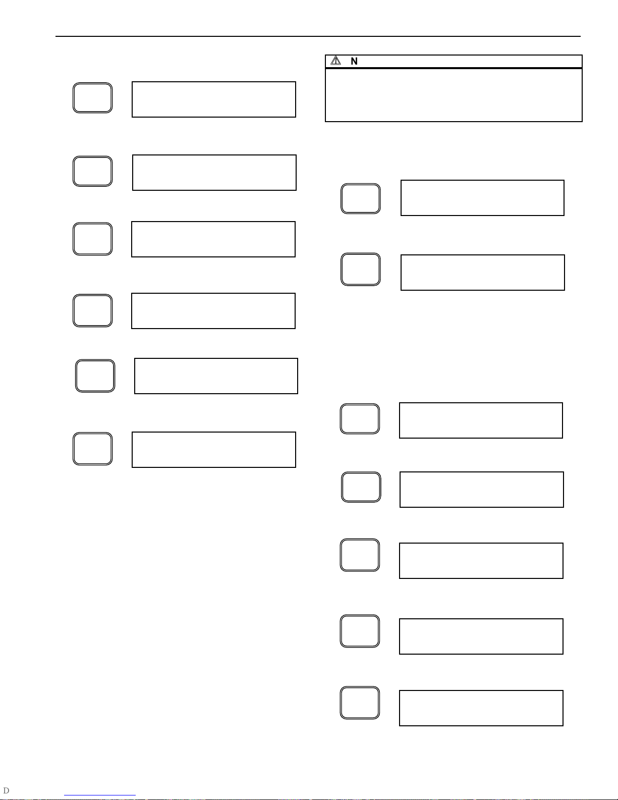
Depress the SELECT DISPLAY button until the OPERATING
TIMES display appears.
OPERATING TIMES
PRESS ENTER
SELECT
DISPLAY
Depressing the ENTER button enters the OPERATING TIMES
menu.
BEGIN TIMES
Depressing the SELECT DISPLAY button displays the
cumulative operating hours of the dryer.
OPERATING HOURS
000000065
SELECT
DISPLAY
PURGE HOURS
000000009
SELECT
DISPLAY
ENTER
Depressing the SELECT DISPLAY button displays the
cumulative hours the dryer has used purge air.
Depressing the ENTER button returns the display to the top of
the OPERATING TIMES menu.
BEGIN TIMES
SELECT
DISPLAY
Depressing the button returns the controller to the
CUSTOMER MODE
OPERATING TIMES
PRESS ENTER
HEATER HOURS
000000009
SELECT
DISPLAY
Depressing the SELECT DISPLAY button displays the
cumulative hours the heater has been energized.
120.26 Dryer - Operation, Installation, Maintenance Manual, and Parts

8
HB Series Desiccant Dryer Models 150-8000
ingersollrandproducts.com
8.1 MOISTURE INDICATOR (STANDARD)
The moisture indicator senses a sample of the control air which is taken
from the dryer outlet. The indicator provides a gross indication of dew
point deterioration at the outlet of the dryer. Under normal operating
conditions, the indicator is blue. In the event of a dryer malfunction or
prolonged dryer shut down, it will turn gray in the presence of moisture.
8.2 HEATER HIGH TEMPERATURE ALARM
WITH INTERLOCK (STANDARD)
The Heater High Temperature Alarm monitors the internal temperature
of the heater housing. Should a component failure occur or system
conditions result in the heater temperature rising above the alarm set
point, the dryer will alarm. During the alarm condition, the heater is
prevented from operating, the Microprocessor Control halts the program
at the point where the alarm occurred and displays the condition in the
Microprocessor Control LCD display. The dryer will be unable to be reset
until the temperature of the heater has fallen below the alarm point. To
reinstate the dryer, depress the RESET button on the Microprocessor
Controller AND manually reset the Heater High Temperature Safety in
the electrical enclosure. Note that the alarm condition will return should
proper corrective action not be taken.
8.3 HEATER FAILURE ALARM (STANDARD)
This feature produces an alarm should the heater fail to generate heat
at the beginning of the heating cycle. During the initial ten minutes of
the heating cycle, the Microprocessor Controller monitors the heater
temperature. Should the heater temperature fail to rise to 150 °F within
the ten minute period, the Heater Failure Alarm will be triggered. During
this alarm condition, power to the heater is removed and the program is
halted. Depressing the RESET button on the Microprocessor Controller
will reinstate the program and provided the heater problem has been
remedied, continue with normal operation.
8.4 FAILURE TO SHIFT ALARM (STANDARD)
Ingersoll Rand Failure To Shift Alarm monitors the dryer sequencing
functions to insure proper dryer operation by sensing the pressure in
each tower via tower pressure switches. Should one of the following
conditions occur, the Microprocessor Controller will communicate the
alarm condition. There are several types of switching failure modes that
can be detected by the Failure To Shift Alarm feature. They are as
follows:
8.4.1 FAILURE TO REPRESSURIZE
At the end of the repressurization stage of the dryer operation,
both towers should be at line pressure. Should the pressure
switches indicate that both towers are not at line pressure, the
Failure to Shift Alarm will activate and the Microprocessor
Control will stop the program at its current position in the
program. The user must depress the RESET button followed
by the ON button, at which time the Microprocessor Control
will start at the beginning of the program.
8.4.2 FAILURE TO DEPRESSURIZE
At the end of the depressurization stage of the dryer
operation, the regenerating tower should be at atmospheric
pressure. Should the pressure switches indicate that this is
not the case, the Failure to Shift Alarm will activate and the
Microprocessor Control will stop the program at its current
position in the program. The user must depress the RESET
button followed by the ON button, at which time the
Microprocessor Control will start at the beginning of the
program.
8.0 ALARMS AND INDICATORS
8.5 HIGH DEW POINT ALARM (INCLUDED WITH EMS)
The purpose of the High Dew Point Alarm is to provide the operator an
alarm indication should the equipment fail to supply air at its designed
pressure dew point. The EMS dew point sensor communicates the
pressure dew point reading to the Microprocessor Controller. Should
the pressure dew point rise above the alarm set point, the
Microprocessor Controller will display the alarm condition on the
controller screen.
8.6 ENERGY MANAGEMENT SYSTEM (EMS) (OPTIONAL)
EMS is an energy savings feature that matches moisture loading and
regeneration energy usage. Drying equipment is typically operated below
full flow rating and/or below maximum water loading capacity of the
desiccant bed. The EMS option includes a dew point transmitter that
transmits the outlet pressure dew point to the Microprocessor Controller.
The Microprocessor Controller displays the outlet pressure dew point in
real-time. The EMS feature utilizes the data communicated from the dew
point sensor and extends the normal timed switching sequence in
proportion to the moisture loading on the dryer. When the EMS feature is
turned off, all switching sequences occur as described in Section 7.7.
When the EMS feature is activated, the drying sequence is governed by
the outlet pressure dew point as measured by the dew point sensor. When
the sampled outlet dew point registers below the customer set point (-43°F
default for -40°F dryers; -102°F on -100°F dryers), an immediate change
in dryer operation will not be noticeable. The dryer will continue its normal
regeneration process through tower re-pressurization. Once the tower is
re-pressurized, both towers will be at line pressure but air will only flow
through the tower indicated by the status panel. Tower switch over
sequence is delayed until the dew point elevates above the EMS set point,
at which point tower switch over will occur.
In addition to monitoring the outlet pressure dew point of the drying
tower, the EMS feature monitors the temperature of the purge exhaust
air on the regenerating tower. After a tower switch-over, and at the
beginning of tower regeneration, the purge exhaust temperature will be
relatively low (normally 90 to 110°F). The purge exhaust temperature will
increase as desiccant regeneration progresses. As nearly all of the
previously adsorbed moisture is driven off of the desiccant, the exhaust
temperature will begin to rise. The timing for the temperature change will
vary depending on moisture loading on the towers. When the purge
exhaust temperature reaches 195°F, which indicates that the desiccant
heating is complete, the Microprocessor Controller will remove power to
the heater and subsequently the blower. If the Cool Sweep feature is
activated, the Cool Sweep runtime will commence. Otherwise, the offline
tower will repressurize and remain pressurized until tower switchover.
8.7 ALARM LIST
The Microprocessor Controller stores the 20 most recent alarm
conditions. These alarms are stored with the type of alarm as well as
the date and time the alarm occurred. This list can greatly facilitate
troubleshooting the dryer and provide an indication of dryer operation
during unattended service. The following describe the method to access
and review the alarms stored in the Microprocessor Controller:
Depress the SELECT DISPLAY button until the ALARM LIST
display appears.
ALARM LIST
PRESS ENTER
SELECT
DISPLAY
8.8 HIGH OUTLET TEMPERATURE (OPTIONAL)
This option provides continuous monitoring of the dryer discharge air
temperature via a thermostat that senses the outlet air temperature
during dryer operation. Should a high outlet temperature condition exist,
the alarm is displayed on the Microprocessor Controller to alert
maintenance personnel of a malfunction. This alarm does not interrupt
the dryer program. Depressing the RESET button will clear the alarm
provided the alarm condition has been addressed. Note that the alarm
will clear automatically once the high temperature condition is corrected.
120.26 Dryer - Operation, Installation, Maintenance Manual, and Parts

9
HB Series Desiccant Dryer Models 150-8000
ingersollrandproducts.com
Depressing the ENTER button enters the ALARM LIST menu.
BEGIN ALARMS
Depressing the SELECT DISPLAY button advances the
menu to the current alarm status.
ALARM OFF
SELECT
DISPLAY
ENTER
8.0 ALARMS AND INDICATORS
Depressing the SELECT DISPLAY button will reveal the previous alarm
condition(s), as well as the remaining available alarm placeholders for
alarms. To EXIT the ALARM LIST, perform the following:
Depressing the button returns the controller to the top of
the ALARM LIST.
BEGIN ALARMS
Depressing the button again returns the controller to
the CUSTOMER MODE.
ALARM LIST
PRESS ENTER
Depressing the SELECT DISPLAY list displays the most
recent of the alarms stored by the Microprocessor Control.
Refer to the diagram at the end of this section for an
explanation of the ALARM LIST Display.
FAIL TO SHIFT
TM 1635 DATE 1104
SELECT
DISPLAY
FAIL TO SHIFT
TM 1635 DATE 1104
Alarm Condition
Date of Alarm
(Date-Month)
Example shows April 11
Time of Alarm
(Military Time)
Figure 3 - Alarm Screen Details
120.26 Dryer - Operation, Installation, Maintenance Manual, and Parts
HB Series Desiccant Dryer Models 150-8000
ingersollrandproducts.com
10
9.0 TECHNICIAN MODE
The Microprocessor Control provides a protected TECHNICIAN MODE
to manipulate several parameters not accessible by the casual operator.
Below is a list of parameters that can be accessed and manipulated by
the technician in the TECHNICIAN MODE:
* NOTE: Setpoints indicated are adjustable ONLY when dryer is
equipped with the Energy Management System / Dew Point Display
option. Setpoints are non-adjustable on dryers
9.1 ENTERING TECHNICIAN MODE
A
WARNING
TECHNICIAN MODE should only be entered by qualified service
personnel. Altering the set points in TECHNICIAN MODE will have a
significant effect on the operation of the dryer. Incorrect set points may
damage dryer and cause potential serious injury.
To enter the TECHNICIAN MODE, perform the following keystrokes:
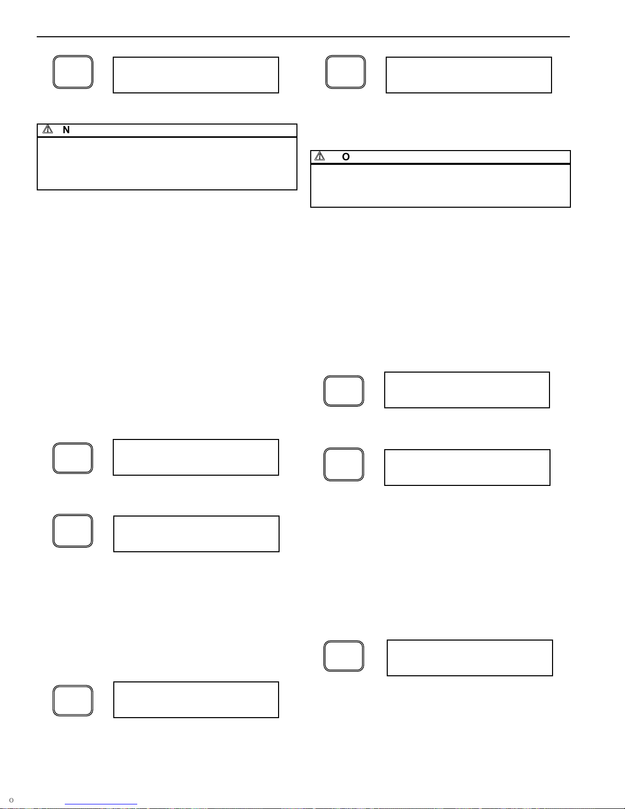
9.2 OPERATING MODE
As described in Section 7, Blower Purge Dryers come standard with the
Bi-Mode feature, permitting the dryer to operate in a blower purge mode
as well as a heatless pressure swing mode. To change the operation
mode of the dryer, perform the following keystrokes:
A
NOTICE
The Microprocessor Controller must be in the OFF position prior to
changing the mode (blower / heatless) of the dryer. After the change is
made and the Microprocessor Control is subsequently turned ON, the
dryer will be in the new mode of operation.
A
CAUTION
Any time the dryer is switched between two operating modes, care
must be taken to ensure the purge adjustment valve is adjusted
correctly. Refer to the specification sheet in this manual for proper
gauge setting.
A
CAUTION
When switching the dryer operation from Heatless to Blower Purge
mode, the purge adjustment valve must be set to the closed position
prior to operating dryer. Failure to do so may cause damage to dryer.
Parameter Display Set Point
OPERATION MODE
OPERATION
MODE
HTLS, BLOWER
PURGE
COOL SWEEP COOL SWEEP OFF, ON
HEATER TEMPERATURE
SETPOINT
HEATER TEMP 300 - 425
ENERGY MANAGEMENT
SYSTEM (OPTIONAL)
EMS OFF, ON
ENERGY MANAGEMENT SYSTEM
SETPOINT (OPTIONAL)
EMS SET POINT -76 - +68
PURGE TEMPERATURE PURGE TEMP OFF, ON
RESTART MODE RESTART LAST, ZERO
EXTENDED HEATING EXTENDED HTG OFF, ON
HIGH DEW POINT ALARM
ACTIVATION (OPTIONAL)
HI DEW POINT OFF, ON
Pressing the “2” and “3” buttons simultaneously enters the
TECHNICIAN MODE.
BEGIN
TECHNICIAN MODE
SELECT
DISPLAY
Depressing SELECT DISPLAY scrolls through the available
parameters.
SET OPMODE
HEATLESS
2
3
Depress the +/- button until the desired operating mode is
displayed. Pressing SELECT DISPLAY saves the current
selection.
SELECT
DISPLAY
+
-
Depress the SELECT DISPLAY button until the SET
OPERATION MODE screen is displayed.
SET OP MODE
BLOWER PURGE
SET OP MODE
HEATLESS
9.3 COOL SWEEP
The Cool Sweep feature cools the regenerating bed prior to switchover.
For applications requiring tight dew point control, using compressed air
to cool the bed prior to switchover will provide a more consistent dew
point and lower outlet compressed air temperatures. To enable the Cool
Sweep mode, perform the following keystrokes:
Depress the +/- button until the desired set point is
displayed. Pressing SELECT DISPLAY saves the current
selection.
Depress the SELECT DISPLAY button until the COOL
SWEEP screen is displayed.
COOL SWEEP
OFF
SELECT
DISPLAY
+
-
COOL SWEEP
ON
9.4 HEATER TEMPERATURE SETPOINT (BLOWER PURGE MODE
ONLY)
The Microprocessor Controller permits the user to adjust the
temperature of the heater, thereby altering the regeneration temperature
in the heated purge mode. Note that the value must be between 300 F
and 425 F.
A
WARNING
The user is advised to only alter the regeneration temperature after
being instructed to do so by Ingersoll Rand factory personnel.
Improper or inappropriate manipulation of the heater temperature can
result in degraded dryer performance, equipment damage and serious
injury. Notify Ingersoll Rand Compressed Air Solutions prior to altering
the heater temperature.
120.26 Dryer - Operation, Installation, Maintenance Manual, and Parts
11
HB Series Desiccant Dryer Models 150-8000
ingersollrandproducts.com
9.0 TECHNICIAN MODE
Depress the SELECT DISPLAY button until the HEATER
TEMPERATURE SET POINT screen is displayed.
HEATER TEMP
375
SELECT
DISPLAY
Depressing ENTER saves the selected set point.
SET
Pressing the SET button permits the value of the HEATER
TEMPERATURE SETPOINT to be changed
HEATER TEMP
___
ENTER
Use the numbers on the keypad to enter the desired value
for the HEATER TEMPERATURE setpoint.
3
HEATER TEMP
3__
8
HEATER TEMP
38_
HEATER TEMP
380
Use the numbers on the keypad to enter the desired value
for the HEATER TEMPERATURE setpoint.
0
HEATER TEMP
380
Use the numbers on the keypad to enter the desired value
for the HEATER TEMPERATURE setpoint.
A
NOTICE
New desiccant has a moisture holding capacity higher than the dryer’s
design regeneration capacity. The desiccant ages in a three- to sixmonth time period at which point it stabilizes to an "aged" state. During
this aging process at initial start-up or after desiccant replacement, the
Energy Management System feature should be deactivated.
9.5.1 ENABLING / DISABLING ENERGY MANAGEMENT
SYSTEM
The following illustrates the method of accessing and
adjusting the Energy Management System feature:
Depress the +/- button until the desired set point is displayed.
Pressing SELECT DISPLAY saves the current selection.
Depress the SELECT DISPLAY button until the ENERGY
MANAGEMENT SYSTEM screen is displayed.
EMS:
OFF
SELECT
DISPLAY
+
-
EMS:
ON
9.5.2 SETPOINT ADJUSTMENT
On dryers equipped with the optional Energy Management
System the setpoint can be adjusted to match the dryers
operation to the desired pressure dew point.
The following illustrates the method of adjusting the setpoint
for the Energy Management System feature:
The following illustrates the method of adjusting the setpoint for the
heater temperature:
9.5 ENERGY MANAGEMENT SYSTEM (OPTIONAL)
The Energy Management System option includes a dew point sensor
that transmits the outlet pressure dew point to the Microprocessor
Controller. The Microprocessor Controller displays the outlet pressure
dew point in real-time. This option package also includes Energy
Management System, an energy savings feature that matches moisture
loading and regeneration energy usage. The Energy Management
System feature utilizes the data communicated from the dew point
sensor and extends the normal timed switching sequence in proportion
to the moisture loading on the dryer.
When the Energy Management System feature is turned off, all
switching sequences occur as described in Section 7.7. When the
Energy Management System feature is activated, the drying sequence
is governed by the outlet pressure dew point as measured by the dew
point sensor. When the sampled outlet dew point registers below the
customer set point (-43°F default for -40°F dryers), an immediate
change in dryer operation will not be noticeable. The dryer will continue
its normal regeneration process through tower re-pressurization. Once
the tower is re-pressurized, both towers will be at line pressure but air
will only flow through the tower indicated by the status panel. Tower
switch over sequence is delayed until the dew point elevates above the
Energy Management System setpoint, at which point tower switch over
will occur.
To enter a negative number, depress the +/- button.
Otherwise, proceed to the next step.
Depress the SELECT DISPLAY button until the EMS SET
POINT screen is displayed.
EMS SET POINT
-43
SELECT
DISPLAY
+
-
EMS SET POINT
-___
SET
Pressing the SET button permits the value of the EMS
SETPOINT to be changed
EMS SET POINT
___
Use the numbers on the keypad to enter the desired
pressure dew point temperature for the EMS setpoint.
4
EMS SET POINT
-4__
Use the numbers on the keypad to enter the desired
pressure dew point temperature for the EMS setpoint.
1
EMS SET POINT
-41_
120.26 Dryer - Operation, Installation, Maintenance Manual, and Parts
12
HB Series Desiccant Dryer Models 150-8000
ingersollrandproducts.com
Depressing ENTER saves the selected set point.
ENTER
EMS SET POINT
-41
A
NOTICE
The Energy Management System set point should not be lower
(wetter) than the dew point adjuster setting. Failure to do so will
prevent the Energy Management System feature from operating. In
addition, when operating in Energy Management System, the purge
flow adjuster should be set to 100%.
9.6 PURGE TEMPERATURE (INCLUDED WITH OPTIONAL EMS
MODE)
On dryers equipped with EMS, the temperature of the purge exhaust is
monitored and displayed on the Microprocessor Controller. After a tower
switch-over, and at the beginning of tower regeneration, the purge
exhaust temperature will be relatively low (normally 90 to 110°F). The
purge exhaust temperature will increase as desiccant regeneration
progresses. As nearly all of the previously adsorbed moisture is driven
off of the desiccant, the exhaust temperature will begin to rise. The
timing for the temperature change will vary depending on moisture
loading on the towers. When the purge exhaust temperature reaches
195°F, which indicates that the desiccant heating is complete, the
Microprocessor Controller will remove power to the heater and
subsequently the blower. On standard units, the towers will then
repressurize and remain repressurized until the tower switchover
sequence is initiated. On dryers with the optional Cool Sweep feature,
the Cool Sweep routine will commence. After cooling, the Purge Valves
close and the Repressurization Valve opens. The off-line tower remains
pressurized until the tower switchover sequence is initiated. Activation of
the Purge Temperature feature is via the Microprocessor Controller.
The following illustrates the method of accessing and activating the
Purge Temperature feature:
Depress the +/- button until the desired set point is displayed.
Pressing SELECT DISPLAY saves the current selection.
Depress the SELECT DISPLAY button until the PURGE
TEMPERATURE screen is displayed.
PURGE TEMP:
OFF
SELECT
DISPLAY
+
-
PURGE TEMP:
ON
To change the start mode from its current selection to the
alternate setting, depress the +/- button until the desired set
point is displayed. Pressing SELECT DISPLAY saves the
current selection.
Depress the SELECT DISPLAY button until the START
MODE screen is displayed.
RESTART
ZERO
SELECT
DISPLAY
+
-
RESTART
LAST
A
NOTICE
The restart modes will only effect restarting should power be
unexpectedly removed from the dryer. After proper shut down, the
dryer will require the user to depress the ON button to initiate the
operation of the dryer program.
9.8 EXTENDED HEATING (OPTIONAL, BLOWER PURGE MODE)
On dryers equipped with the Energy Management System option, the
dryer may be operated in an extended heating mode. In this mode, the
heating cycle is extended while the Energy Management System
function prolongs the drying cycle. This feature is particularly useful
when operating the dryer with new desiccant. As described earlier in
Section 2, new desiccant has the ability to adsorb more moisture than
the dryer can desorb in a fixed regeneration cycle. With the Extended
Heating operation, the Energy Management System feature can be
used immediately without the need to age the desiccant. This feature is
provided only when the dryer is equipped with the Energy Management
System. To enable the Extended Heating mode, perform the following
keystrokes:
Depress the +/- button until the desired set point is displayed.
Pressing SELECT DISPLAY saves the current selection.
Depress the SELECT DISPLAY button until the EXTENDED
HEATING screen is displayed.
EXTENDED HEATING
OFF
SELECT
DISPLAY
+
-
EXTENDED HEATING
ON
Depress the SELECT DISPLAY button until the HIGH DEW
POINT screen is displayed.
HIGH DEW PT
OFF
SELECT
DISPLAY
9.0 TECHNICIAN MODE
9.7 RESTART MODE
Ingersoll Rand dryers can be configured to restart in one of two
operating modes. As described in Section 7.8, the dryer may be
configured for Manual operation (factory default) or Auto Restart, which
permits the dryer to operate automatically once power is re-applied to
the dryer after a power failure. The following illustrates the method of
accessing and adjusting the different start modes for the dryer:
9.9 HIGH DEW POINT ALARM (OPTIONAL)
9.9.1 DESCRIPTION AND ACTIVATION
When the dryer is equipped with the optional Energy
Management System feature, the dew point sensor transmits
the dew point to the Microprocessor Control Should the outlet
pressure dew point exceed the customer specified set point,
High Dew Point Alarm will activate.
The following illustrates the method of activating the High
Dew Point Alarm feature:
120.26 Dryer - Operation, Installation, Maintenance Manual, and Parts
13
HB Series Desiccant Dryer Models 150-8000
ingersollrandproducts.com
Depress the +/- button until the desired set point is displayed.
Pressing SELECT DISPLAY saves the current selection.
+
-
HIGH DEW PT
ON
9.9.2 SETPOINT ADJUSTMENT
On dryers equipped with the optional Energy Management
System, the High Dew Point Alarm setpoint can be adjusted
as follows.
The following illustrates the method of adjusting the setpoint
for the High Dew Point Alarm feature:
9.0 TECHNICIAN MODE
To enter a negative number, depress the +/- button.
Otherwise, proceed to the next step.
+
-
HI PDP SETPOINT
-___
Depressing ENTER saves the selected set point.
ENTER
Use the numbers on the keypad to enter the desired
pressure dew point temperature for the EMS setpoint.
2
HI PDP SETPOINT
-2__
Use the numbers on the keypad to enter the desired
pressure dew point temperature for the HIGH DEW POINT
ALARM setpoint.
1
HI HUMID SETPOINT
-21_
HI PDP SETPOINT
-21
9.10 PROGRAM JOG
All heated purge and blower purge dryers come equipped with a
Program Jog feature that is accessible via the Microprocessor
Controller. This feature allows the dryer cycle to be accelerated for
troubleshooting and routine inspection purposes. By accessing the
Program Jog routine in the Microprocessor Control, the customer can
advance the program to the next program step. Note that the program
advance feature will not advance through all steps of the program.
A
WARNING
When the Program Jog is initiated in the middle of the heating cycle,
advancing the program without allowing normal tower cool down will
result in an outlet air temperature that may exceed 300°F. As such,
proper precautions must be taken to protect downstream equipment
from high temperature exposure.
A
NOTICE
During the Program Jog routine, the display may show intermediate
steps in the program that are not active in the current program set up.
This should be considered normal operation.
The Microprocessor Controller will only permit the jog function during
specific stages of the program. Should the program be at a stage where
the program can not advance, the following will be displayed:
Depress the SELECT DISPLAY button until the HIGH DEW
POINT SET POINT screen is displayed.
HI PDP SETPOINT
-10
SELECT
DISPLAY
SET
Pressing the SET button permits the value of the HIGH
DEW POINT ALARM SETPOINT to be changed
HI PDP SETPOINT
___
Depress the SELECT DISPLAY button until the JOG MODE
display appears. The WAIT prompt will appear should the
program not be able to advance at this stage.
JOG MODE
WAIT
SELECT
DISPLAY
Should the program be at a stage whereby the Microprocessor Control
permits the jog feature, the following will be displayed:
Depress the SELECT DISPLAY button until the JOG MODE
display appears. The PRESS ENTER prompt will appear,
along with the current step and remaining time, should the
program be able to advance at this stage.
JOG: ENT TO JOG
STEP 6 TME10699
Depressing the ENTER button advances the program to the next
step. The display will indicate the next step has been initiated.
JOG MODE
STEP 8 TME00550
ENTER
9.11 SHUTDOWN SEQUENCE
Pressing the OFF button turns the dryer off and initiates a 30 second
shutdown sequence that repressurizes the offline tower, and leaves both
inlet flow valves open and both purge valves closed.
A
NOTICE
The Program Jog advances steps #6, #8, #20 & #22, which are the
longest program steps. The balance of the steps are not advanced in
Program Jog Mode.
A
NOTICE
To exit the TECHNICIAN MODE, press “Select Display” key to the
initial “SET OPMODE” screen or “BEGIN TECHNICIAN MODE” screen
and depress the button to return to the CUSTOMER MODE.
A
NOTICE
The High Dew Point Alarm set point should not be greater than the
Energy Management System set point. Failure to do so will result in an
alarm indication. Ingersoll Rand recommends setting the High Dew
Point Alarm at least 10°F wetter than the Energy Management System
setpoints.
120.26 Dryer - Operation, Installation, Maintenance Manual, and Parts
10.0 INSTALLATION AND INITIAL START-UP
10.1 EQUIPMENT APPLICATION GUIDELINES
Ingersoll Rand Regenerative air dryers are shipped complete with
desiccant up to and including model HB2100. On larger units, the
desiccant is packaged separately for ease in handling. Refer to Section
11.6 for desiccant fill procedures.
To achieve the best dryer performance, carefully check that the design
and installation requirements outlined below are satisfied.
Ingersoll Rand dryers are available with an operating range from 75 150 PSIG. Air available for your usage will vary with operating pressure.
The maximum design pressure of the standard Desiccant Dryers is 150
PSIG. For units that require higher operating pressures, consult your
Ingersoll Rand representative.
Dryers are sized according to flow and pressure drop, not pipe size. The
difference between the inlet and the outlet flow is the amount of purge
air required. This air is exhausted to atmosphere and is not available for
use downstream. Make certain air supply to dryer meets air demand
plus purge air requirements.
A
NOTICE
The standard dryer is not rated for any gas other than air.
A
NOTICE
Ingersoll Rand recommends that the mufflers be cleaned after initial startup to remove any desiccant dust generated during shipment. After running
dryer for initial 30 minute period, de-energize / depressurize dryer and
remove mufflers. Disassemble and clean the removable insert inside the
muffler core. Reinstall mufflers prior to operating dryer.
10.2 LOCATING AND MOUNTING
The dryer must never be installed where air and/or ambient temperature
exceeds 120°F or drops below +35°F. Locate dryer to avoid extremes
of heat and cold from ambient or other conditions. Where applicable,
dryer towers may be insulated to reduce heat loses. Avoid locating
dryer outside or where it is exposed to the elements.
The dryer, or any air system component, must be located to avoid
exposure to pulsation in the compressed air as well as possible surges
due to fluctuating demand. In addition, care must be used to minimize
exposure to vibration transmitted through mounting pads or piping.
Provide adequate space around the dryer for normal maintenance
requirements and service.
If the dryer is shipped with the desiccant packaged separately, install the
desiccant after locating and mounting. Desiccant has been provided
separately to minimize handling difficulty and placing unnecessary
stress on the dryer assembly.
Bolt the dryer to the foundation using the bolt holes provided in the base
frame. Anchor bolts should project a minimum of 3.5 inches above the
foundation and allow proper nut and washer assembly.
10.3 PIPING
Pipe the compressed air lines to the inlet and outlet connections. Locate
the pre-filters as close as possible to the dryer. Ensure the positioning
allows for ease of servicing.
Note that the wet air inlet is located at the dryer's upper manifold and the
dry outlet air is located at dryer's lower manifold. In situations where air
supply is required 24- hours a day (it is undesirable to interrupt the airflow),
a three-valve bypass system is recommended to bypass the dryer. To
keep pressure drop at a minimum, use the fewest elbows necessary
Once all piping has been connected all joints, including those on the
dryer, should be soap bubble tested at line pressure to ensure no joints
have been damaged in transit and site placement.
10.4 FILTRATION
It is important that a pre-filter and a post-filter be provided in your dryer
installation. These filters are included with each dryer. They are mounted
on model HB1500 and smaller.
A
NOTICE
All dryers must have proper filtration. Liquid water and oil must be
removed before the air enters the dryer. Ensure separators, pre-filters
and drains are in good working order. Failure to do so will void
warranty.
It is recommended that a mechanical separator be installed immediately
preceding the pre-filter to remove the bulk liquid and entrained water.
Coalescing pre-filters, located before the dryer, protect desiccant beds
from contamination by oil, entrained water, pipe scale, etc., thereby,
extending dryer desiccant life. Locate pre-filters as close to dryer as
possible. FAILURE TO PROVIDE AND MAINTAIN A HIGH
EFFICIENCY COALESCING PRE-FILTER WILL VOID DRYER
WARRANTY.
Post-filters, located after the dryer, help eliminate the possibility of
desiccant dusting carrying over into the air system.
A
WARNING
High temperature filters must be used to prevent rupture possibility in the
event dryer failure should occur. Consult your Ingersoll Rand
representative for appropriate filter selection.
10.5 DEW POINT TRANSMITTER INSTALLATION (OPTIONAL)
On dryers equipped with EMS, the dew point transmitter is shipped in a
separate container within the electrical enclosure to protect the
transmitter during shipment. Prior to using the EMS feature, the
transmitter must be installed in the sensor block located on the side of
or behind the electrical enclosure and the transmitter cable fastened to
the sensor. Note that the transmitter should only be installed when the
dryer is ready to be commissioned.
To install the Dew Point Transmitter:
• Remove Transmitter from original packaging.
• Verify that Washer is placed below Transmitter hex.
• Thread the Transmitter into the Sensor Block as shown.
• Attach the Transmitter Cable to the Transmitter. Be sure to fully
engage the Transmitter Cable Securing Screw into the mating thread in
the Transmitter.
14
HB Series Desiccant Dryer Models 150-8000
ingersollrandproducts.com
120.26 Dryer - Operation, Installation, Maintenance Manual, and Parts
 Loading...