

Ingenico ELITE 790 User Manual

The Global Provider of Secured Transactions
ELITE 790
U
Ser’s Manual
July 2003


July 2003
3
Table of Contents
I- TERMINAL DESCRIPTION..........................................................................5
1- Introduction..............................................................................................................................5
2- The Terminal .............................................................................................................................6
3- The Terminal Connections...................................................................................................6
4- The Base Connections..........................................................................................................6
5- The Keyboard - Utilisation....................................................................................................7
6- The Card Reader.....................................................................................................................8
7- Wireless functionality.............................................................................................................8
II- ELITE 790 TECHNICAL OVERVIEW........................................................11
1- Terminal features.................................................................................................................11
2- Display....................................................................................................................................11
3- Printer......................................................................................................................................11
4- RS232 Interface (base)........................................................................................................12
5- Modem....................................................................................................................................12
6- SIM Slots.................................................................................................................................13
7- Serial Connector..................................................................................................................13
8- Hands free kit Connector...................................................................................................13
9- Power Supply........................................................................................................................14
10- Operating Range...............................................................................................................14
III- INSTALLATION PROCEDU RES...............................................................15
1- Entering Date and Time......................................................................................................15
2- Telephone Network Parameters......................................................................................16
3- Printing Totals.......................................................................................................................17
4- Options menu........................................................................................................................18
5- Application Software Downloading Procedure...........................................................19
6- Configuration Receipt .........................................................................................................20
7- GSM Menu..............................................................................................................................21
8- Security Menu (Optional)....................................................................................................23
9- GSM - SMS options..............................................................................................................24
IV- PRACTICAL INFORMATION...................................................................25
1- Charging the battery pack.................................................................................................25
2- Cleaning Procedures..........................................................................................................26
3- Changing the paper roll......................................................................................................26
V- RECOMMENDATIONS...............................................................................27
1- Security...................................................................................................................................27
2- Connection to PSTN...........................................................................................................28
3- RF Safety................................................................................................................................28
4- General safety.......................................................................................................................29

ELITE 790 Terminal
4

July 2003
5
I- Terminal Description
1- Introduction
The ELITE 790 is a portable payment terminal for a radio transmission module (voice + data)
using the GSM standard and a modem for PSTN communications. This terminal was created to
process all payments made by magnetic or smart cards.
The ELITE 790 has an integrated thermal printer which prints two copies of each receipt.
The ELITE 790 terminal benefits from a modular conception, which allows a number of different
applications to run on the terminal independently without jeopardising software security.
Your retailer or installer will be able to give you the necessary information on
all available applications and their installation details.
ELITE 790 Terminal
6
2- The Terminal
The terminal case contains the following elements:
• The portable terminal and base.
• A cable that connects the terminal to a telephone line.
• A power pack that connects the terminal to a 115 or 230 volt power point (depending
on the country)
3- The Terminal Connections
There are two connectors on the back of the terminal. (See page 4)
The blue jack is for portable hands free kit. The black connector is suitable for a peripheral
device like a barcode scanner, for which a specific software application is required.
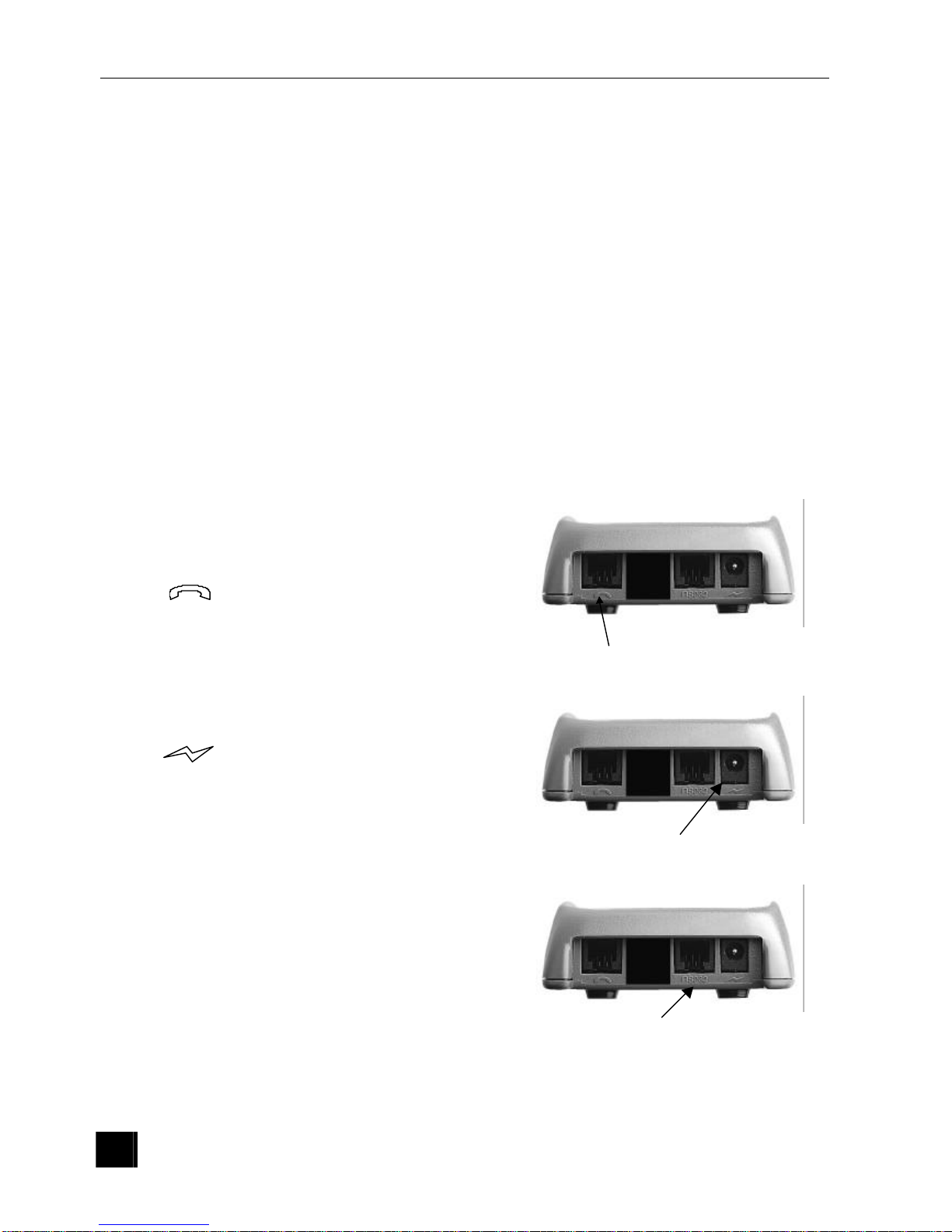
4- The Base Connections
0 Telephone Connection
The compact telephone cable connection
supplied with the Elite terminal must be
connected to the port marked with the
symbol . The telephone connection
(RJ11) must be connected to the telephone
socket in the wall.
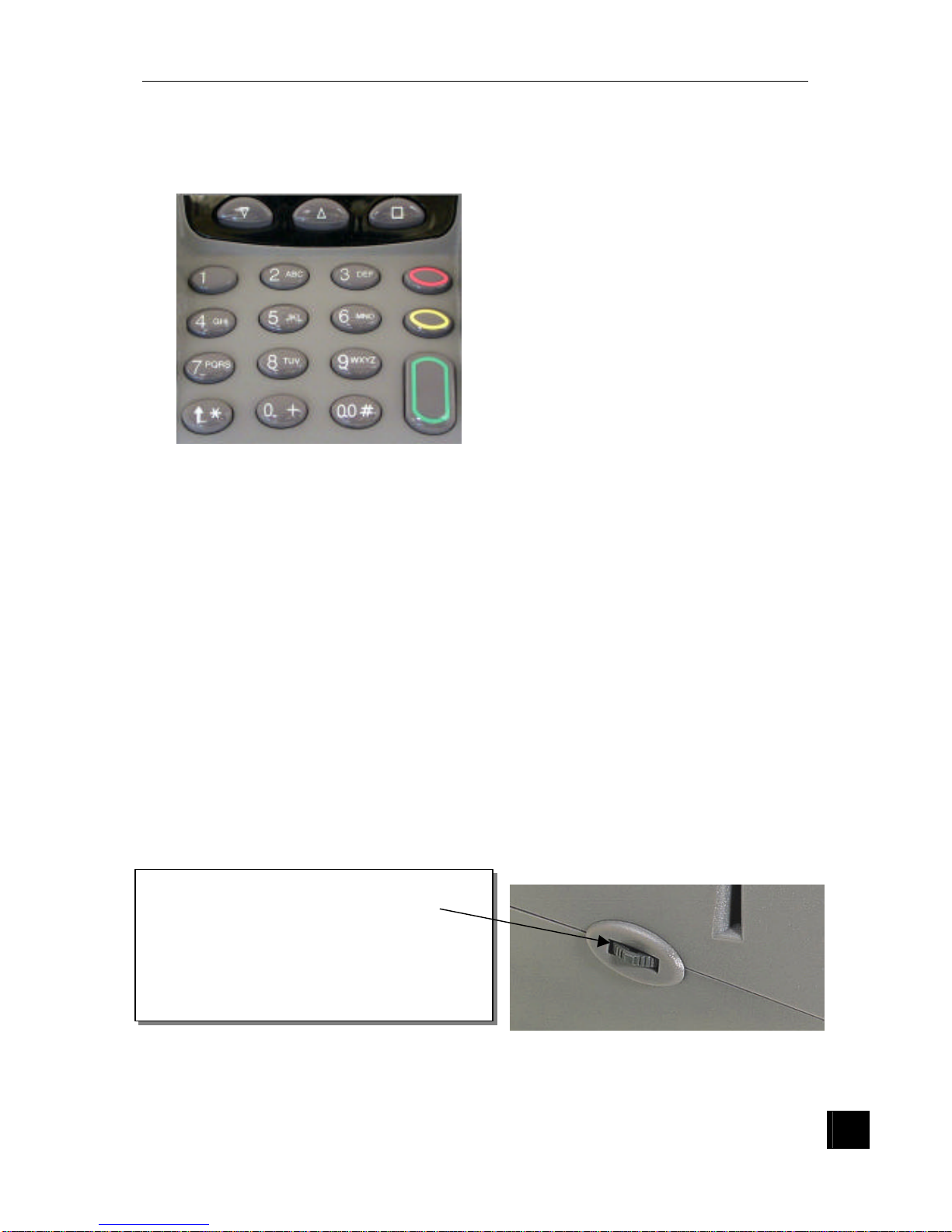
0 Electrical Connection
The small jack connection to the power pack
is plugged into the port marked with the
symbol . The twin pronged electrical
plug is connected to an electrical point (115
or 220 volts, depending on the country).
Only use the power supply pack
provided with the terminal.
0 Connection to an external peripheral device
Some peripheral devices suc h as a cheque
readers can also be connected.
The ELITE 790 terminal must be powered
off before connecting the cable on the base
to the RS232 port.
Telephone line
Power Supply
Serial port
July 2003
7
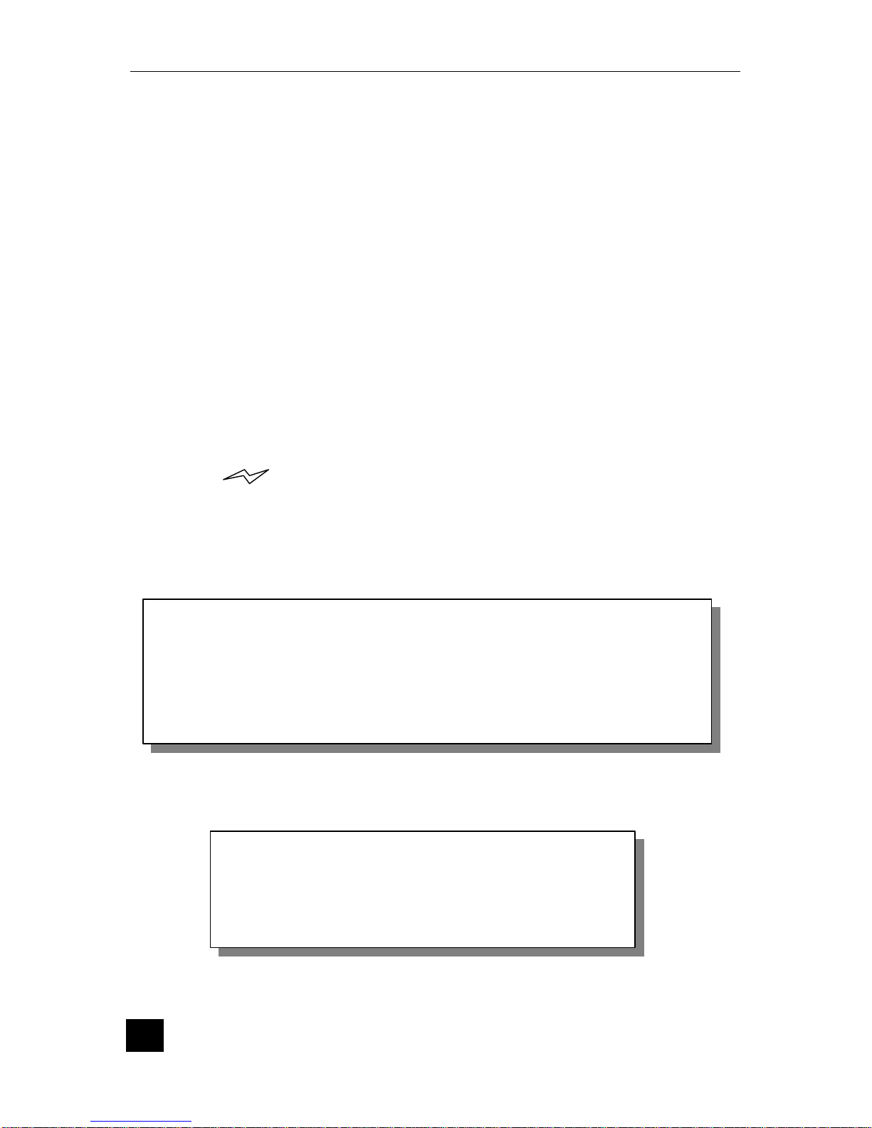
5- The Keyboard - Utilisation
The 2 key gives the operator access to
all of the different menus on the terminal
including the “system” menu which manages
the standard functions of the Elite 790, such
as: modification of the date and the time,
modification of download and line
parameters.
• The 3 and 4 keys allow
navigation through scrolling
application menus and the
“system” menu. During “vocal use” of the terminal, these keys adjust the
volume.
• The key 7 prompts a paper feed of a couple of centimetres. This function
is only active when the terminal is in the idle state.
• The A key is used to validate any information read by or entered into the
terminal. It is also the power switch when the terminal is in portable mode.
• The B key cancels the occurring command after which, it returns
the terminal to idle state.
• The C key deletes the last character entered, and
in certain cases is used where an override is requested.
• The key marked d can only be used for entering amounts ;
more specifically it allows the operator to enter amounts in cents.
The navigation wheel has the same function
as the following 3 keys
2 Push up the navigation wheel
3 Turn the wheel “up”
4 Turn the wheel “down”
ELITE 790 Terminal
8
6- The Card Reader
0 Magnetic Stripe Card
The card can be read when swiped either from right to left, or left to right. The magnetic
stripe on the card should face the printer and the card should be swiped through the
reader freely and without hesitation.
0 Card
Introduce the card horizontally into the terminal, the chip facing up, as indicated and
leave the card in position until the transaction is complete.
7- Wireless functionality
The ELITE 790 terminal is portable ; A fully charged battery will perform 100
transactions before the terminal has to be returned to the base for charging.
The symbol on the upper right hand side of the display indicates a correct
connection between the terminal and the base.
A low battery is indicated by a message « -BAT- » on the display followed by a beep.
Within one hour of this message appearing, the battery pack must be recharged. The
terminal can perform a few transactions in this time.
In portable mode, the ELITE 790 terminal will switch to power save mode after 50
seconds of inactivity or if the B key is pressed.
The name of the network, to which the terminal is registered, appears on the display and
a graph indicates the RSSI (Reception Signal Strength Indicator).
Warning
When the terminal is powered off, the GSM standby
mode (to receive incoming calls) uses battery power,
reducing the number of transactions between
“charge-ups”.
Warning
Do not use a “fast charge” if the terminal is returned to the base after
each transaction. The batteries may be damaged and their lifetime
reduced. A fast charge battery should only be charged when empty.
If the terminal is placed on the charger after
each transaction, a “slow
charge” must be used to protect the battery.
July 2003
9
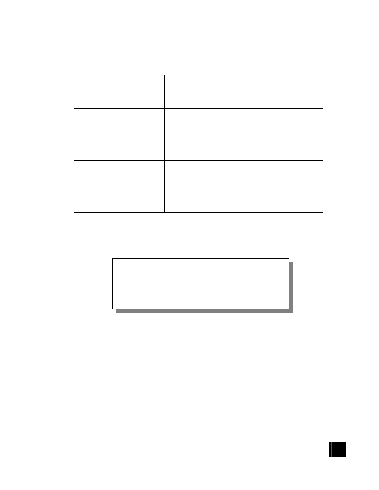
When the terminal is switched on, the following messages could appear on the
terminal display:
INACTIVE GSM A problem is encountered with the GSM module. If
after having removed the battery pack a few times
the same message appears then consult the
terminal issuer.
MISSING SIM
This message appears if the SIM is invalid or not
correctly inserted.
BLOCKED SIM
This message appears if SIM blocked or if the
PUK has been entered incorrectly 10 times.
NO GSM SERVICE
Invalid SIM card or service not available. Contact
your retailer.
NETWORK SEARCH
This message appears while the terminal is
searching for a network. Once the terminal has
found it, this message is replaced by the operator
name.
POWER SAVE MODE
When the power save mode is selected.
Warning
Before using the terminal for the first time, the
batteries
must be fully charged. This is indicated
by a green light on the base which goes out when
this process is complete.

ELITE 790 Terminal
10
 Loading...