


iCT250
Terminal User Guide
iCT250

Page 1
Contents
Section Title Page
1. Introduction 2
2. Important Safety Instructions 2
3. Declaration of Conformity 5
4. Installing the Terminal 6
5. Using the Terminal 8
6. Sale (Inserting a Card) 10
7. Sale (Swiping a Card) 11
8. Voice Referrals 12
9. Setting the Referral Password 13
10. Refund 14
11. Purchase with Cashback 15
12. Cash Advance 15
13. Add Gratuity as a Percentage 16
14. Purchase with Gratuity (Restaurants) 16
15. Refund with Gratuity 18
16. Pre-Authorisation 18
17. Completion 19
18. Key Entering Card Details and Mail Order Transactions 20
19. Reversal 22
20. PIN Entry Failure 22
21. Cancelling Transactions 23
22. Clearing Mistakes 23
23. Printing Duplicate Receipts 24
24. X and Z Totals 24
25. Waiter Totals 25
26. End-of-Day Banking 25
27. Entering Function Codes 26
28. Waiter ID’s (Restaurants) 27
29. How to Change the Date and Time 29
30. How to Print a Transaction Log 29
31. How to Change a Paper Roll 30
32. Security Warning Notice 30
33. Helpful Hints 31
34. Miscellaneous Prompts 32

Page 2
1. Introduction
This guide will detail how you install and use your ICT250 terminal, including Safety Instructions and
instructions on transaction processing, printing reports and general maintenance of the terminal.
2. Important Safety Instructions
Upon receipt of your terminal you should check for signs of tampering of the equipment. It is strongly
advised that these checks are performed regularly after receipt. You should check, for example: that
the keypad is firmly in place; that there is no evidence of unusual wires that have been connected to
any ports on your terminal or associated equipment, the chip card reader, or any other part of your
terminal. Such checks would provide warning of any unauthorised modifications to your terminal, and
other suspicious behaviour of individuals that have access to your terminal.
Your terminal detects any ‘tampered state’. In this state the terminal will repeatedly flash the
message ‘Alert Irruption!’ and further use of the terminal will not be possible. If you observe the
Alert Irruption!’ message, you should contact the terminal helpdesk immediately.
You are strongly advised to ensure that privileged access to your terminal is only granted to staff
that have been independently verified as being trustworthy.
CAUTION: Never ask the customer to divulge their PIN Code. Customers should be advised to ensure
that they are not being overlooked when entering their PIN Code.
General Safety Information
This equipment has been designed and manufactured to meet international safety standards but,
like any electrical apparatus, due care must still be taken.
• Do read and understand the instructions before using the equipment.
• Do Not expose this apparatus to rain or moisture. For indoor use only.
• Do Not remove any screws or non-operator accessible covers.
• Do Not insert any metallic objects.
• Do Not stack telephone splitters.
• Do Not allow liquid to spill into cabinet openings.
• Do Not allow anything to rest on the power or telecomm cords and ensure all cables are
routed to prevent damage or accidental contact.
• Do Not continue to operate the equipment if you are in any doubt about it working normally,
or if it is damaged in any way. Switch off then withdraw the mains plug and consult your
service agent.
Service Requirements
Operator Access (ESD Precaution)
This is an Electrostatic (ESD) sensitive area. As a minimum, the operator should be ‘Electrostatically
Discharged’ via his/her hand to a suitable metallic earthing point prior to opening this area.
There are no other user serviceable parts inside. In the event of equipment malfunction, unplug the
power supply. It is the responsibility of users requiring service to report the need for service to the
authorised Service Agent.

Page 3
Maintenance
Cleaning the Case
• DO NOT allow any water to enter inside the case. Remove any dust from the case using a
damp cloth. To clean off accumulated dirt and grime, use a damp cloth that has previously
been dipped in mild soap and water. Wring out thoroughly to remove excess water before use.
• DO NOT use solvents, cleaning fluids or abrasives. These materials could damage the plastic
housing and any exposed contacts.
External Power Supply
• This apparatus is intended for use when supplied with power from a low voltage external
power supply.
• Only an Ingenico approved power supply (CE Marked) specified for use with this Terminal may
be used.
• Since this product does not have a disconnect device (ON/OFF switch), the Terminal and Power
Supply must be installed near a suitable power socket which is easily accessible.
• In the event of a hazard or malfunction, the Power Supply Unit should be switched off at the
socket before being unplugged from the mains.
• The power supply output lead should only be plugged into the product power input socket.
• The power supply will provide adequate power for the Terminal. The user should ensure that
all other auxiliary apparatus, drawing power from the host, does not overload the power
supply.
• Operate only a from a power source as specified on the Power Supply Unit.
A damaged mains cord (if not a replaceable type) or low voltage secondary input lead cannot be
replaced by the user, the unit must be returned to the authorised service agent for essential repairs
and/or replacement.
Connections
Interconnection to other equipment via the externally accessible ports on the Terminal must only be
made as follows:
Power Supply Input: Operates at Safety Extra Low Voltage (SELV). Connect only to an Ingenico
approved Power Supply (CE Marked) specified for use with the Terminal.
Port(s), 6 way: The RS232 type port(s) operate at SELV and must only be connected to a module of
the same type ie. SELV.
Public Switched Telephone Network (PSTN) Line, 6 Way: MUST only be connected to a PSTN socket
e.g. Telephone wall socket, PBX etc.
Under no circumstances must the PSTN cable be inserted into the RS232 ports. Take due care when
attaching cables.

Page 4
External Cables
DO NOT use any other external cables and/or cable lengths (must be less than 3 metres long) other
than those specified and/or supplied by the manufacturer. Ensure all cables are routed to prevent
damage or accidental contact.
MODEM
General Description
The Terminal has an integral modem that allows the Terminal to transfer transaction data to card
companies host computer systems.
The internal modem supports: CCITT V22bis/V22/V21/V32, V32bis, V34 data transfer protocols.
It has an automatic dialling facility.
Disclaimer
This equipment has been designed for connection to the local Public Switched Telephone Network
(PSTN). The apparatus must not be subjected to any modification, in any material way, unless
authorised by Ingenico. Nor must it be used with:
Internal Modem Software that has not been formally accepted by the manufacturer. External control
Software or external control equipment which causes operation of the modem or associated call
set-up equipment to contravene the requirements of the PSTN Network.
Systems to which the Modem may be connected
This Modem is only approved for connection to the following telecommunications systems:
1. The Public Switched Telephone Network (PSTN).
2. Any equivalent service run by any Licensed Telecommunications Network Operator.
3. Private Branch Exchange (PBX) extensions, being a Branch Telecommunications System operating
under a license.
4. The Modem is not suitable for shared service or 1+1 carrier systems nor as an extension to a
payphone.
PLEASE NOTE: It cannot be guaranteed that the Modem will operate correctly under all possible
conditions of connection to PBX’s. Any cases of difficulty should be referred in the first instance to
Ingenico.
Connection
The modem is connected to the PSTN via a standard plug and flexible cord, which requires a suitable
compatible socket (and adaptor if required).
Terminals connected to phone lines where a broadband service is present must be connected
through an ADSL microfilter.
Dialling
This modem is suitable only for connection to direct exchange and/or PBX lines which provide Dual
Tone Multi Frequency (DTMF) dialling facilities.
Ringer Equivalence Number (REN)
To determine the total number of items of apparatus that should be connected simultaneously to
an exclusive PSTN line, the total REN values of each of the items of apparatus connected to the line
should not exceed the maximum REN value 4.0. This value includes any Network operator provided
instrument, each of which is assumed to have a REN value of 1.0 unless otherwise marked.
Page 5
3. Declaration of Conformity
The CE marking indicates that the EFT930G complies with the requirements of European Directive
1999/5/EC of 9th March 1999. on Radio and Telecommunications Terminal equipment for:
• The protection of the health and safety of the user and any other person.
• The protection requirements with respect to electromagnetic compatibility.
and complies with the following harmonised standards:
And, for the whole range, complies with the European approval specification on connecting
terminals with DTMF dialling to the public switched telephone network (Council Decision 1998/482/
EC, Council Decision 1999/303/EC)
• TS 103021-1/2/3 /09-2003
• TR 103000-1/2/3/4 /06-2003
• ES 201187 /03-1999
WEEE Directive
The product belongs to the family of electrical and electronic equipment. Therefore it is subjected to
the WEEE Directive which requires the collection and recycling at the end of the life of the product.
Ingenico products present the symbol for the marking of electrical and electronic equipment as
required by the WEEE Directive.
The crossed through wheeled bin printed on the product gives information about the
requirement not to dispose of WEEE as unsorted municipal waste and to collect such WEEE
separately.
To ensure that the product is collected and recycled with respect to the environment, you must
contact your supplier (contact the Ingenico local office or the commercial head office in charge of
your country on www.ingenico.com <<contact us>> page).
The abandonment or uncontrolled disposal of waste can harm the environment and human health.
So, by recycling your product in a responsible manner you contribute to the preservation of natural
resources and the protection of human health.
Batteries
If your product contains batteries they must be disposed of at the appropriate collection points.
EN 60950-1 /12-2001 According to 73/23/EEC (Low Voltage Directive)
EN301489-1/7 / 08-2000 According to 89/336/EEC (EMV Directive)
EN301511 / 12-2000 According to 1999 /5/ EEC (R&TTE Directive)
EN50360 / 07-2001 According to 1999 /519/ EEC (R&TTE Directive)
Page 6
5. Key in your Merchant Number and press the GREEN
button.
The terminal will start to dial the Host computer and a
number of communication messages will be displayed.
6. The terminal may then contact any card acquirers it is
configured to accept. Further communication messages
will be displayed.
Dual Comms Mode
You should use the keys to highlight the required
option and then press the GREEN button. For PSTN
installation select Telephone (PPP).
Connection Method
Telephone (PPP)
Local Network
4. Installing the Terminal
Installing the Terminal via PSTN
Before switching the power on at the mains socket, ensure
the mains supply is connected to the circular power port
on the terminal’s connector box.
Ensure the supplied telephone cable is connected to the
telephone IN port on the terminal’s connector box, and
into your telephone socket.
PLEASE NOTE: If you have Call Waiting and select NO when prompted, the terminal will be unable to
dial for authorisation when a call message is waiting.
Position the terminal in a clear area where the display can be read and the keypad and card reader
are easily accessible. Ensure that you have a Merchant Number to hand. This can be found on your
Welcome Letter.
Now switch the power on at the mains supply.
1. Ensure the telephone line is connected to the terminal and to the wall socket and then press the
GREEN button.
If your terminal is connected via a direct line select NO by pressing the YELLOW button.
2. If it is connected to a Switchboard/PABX select YES by pressing the GREEN button.
3. If you selected the Switchboard/PABX option, key in
the number used to get an outside line (often 9) and then
press the GREEN button.
4. If your telephone line has Call Waiting or 1571 press the
GREEN button.
Terminal Installation
Plug in Phone Line
and then press ENTER
Dial Prex Required ?
Enter=YES Clear=NO
Key in the Number used to get
an Outside Line
and then press ENTER
Does the Tel. Line have
Call Waiting or 1571 ?
Enter=YES Clear=NO
Terminal Installation
Key in Merchant No.
and then press ENTER
Terminal Installation
Connecting to
<Acquirer Name>
Please Wait...
Page 7
7. An installation report will then be printed displaying the
card types that your terminal will accept.
8. Finally, the terminal will dial the Host computer to
report the successful installation.
Installation is now complete and the terminal will display
the READY prompt. Your terminal is now ready for use.
Check the date and time on your terminal. If this needs to
be corrected refer to Section 29 of this guide for further
details.
Installing the Terminal via Ethernet (IP)
Ensure the mains supply is connected to the circular power port on the terminal’s connector box.
Ensure that the Ethernet cable is connected to the ETH port on the terminal’s connector box, and to
your router or network point.
Position the terminal in a clear area where the display can be read and the keypad and card reader
are easily accessible.
Ensure that you have your Merchant Number to hand. This can be found on your Welcome Letter.
READY
Merchant Number
12345678
READY
Merchant Number
12345678
Dual Comms Mode
You should use the keys to highlight the
required option and then press the GREEN button to select.
For installation over IP select Local Network.
1. Ensure the Ethernet cable is connected to the terminal
and press the GREEN button.
2. Key in your Merchant Number and press the GREEN
button.
The terminal will attempt to connect to the Host com-
puter and a number of communication messages will be
displayed.
The terminal may then contact any acquirers it is
configured to accept. Further communications messages
will be displayed.
3. An installation report will then be printed displaying the
card types that your terminal will accept.
Finally, the terminal contact the Host computer to report
the successful installation.
Connection Method
Telephone (PPP)
Local Network
Terminal Installation
Plug in Network
Cable
and then press ENTER
Terminal Installation
Key In Merchant No.
and then press ENTER
Terminal Installation
Connecting to
<Acquirer Name>
Please Wait...
READY
Merchant Number
12345678
Page 8
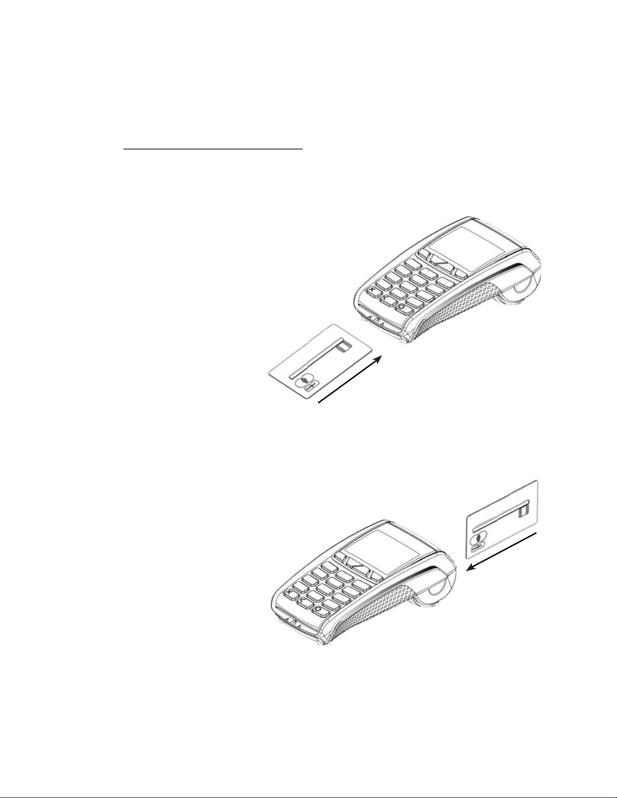
Swiping a Card
The card should be swiped with the black magnetic stripe facing the terminal and running along the
bottom of the card.
Make sure that the bottom of the card runs firmly along the
bottom of the card swipe and that the card is swiped at
even speed.
The speed of the card swipe should not be
too slow as this can sometimes cause problems
when the terminal is reading the card.
PLEASE NOTE: It is important to swipe cards correctly through the terminal so that they can be read
by the card reader.
4. Installation is now complete and the terminal will display the READY prompt. Your terminal is
now ready for use.
Check the date and time on your terminal, if this needs to be corrected refer to Section 29 of this
guide for details on how to do this
.
5. Using the Terminal
Inserting a Chip Card into the Terminal
The card should be inserted into the terminal with the chip facing uppermost. The terminal can
detect if a chip card has been swiped as a magnetic card.
If the card has not been inserted previously, it will prompt you to
insert the card.
If the card is inserted the wrong way or there is a problem
with the chip, the terminal will prompt for the card to be
removed and inserted again.
The terminal will prompt you when the card is
to be removed.
Page 9
The cardholder should press the YELLOW button to scroll
through the options and then press the GREEN button to
select the appropriate one.
Application Selection
Some cards support multiple card schemes and during the transaction flow the cardholder may
be required to choose which card scheme to use. At this time you should hand the terminal to the
Cardholder.
(Please refer to Section 6 of this guide for instructions on how to complete a Sale.)
Using the Menus
The Transaction Menu enables you to perform a transaction on the terminal.
At the READY prompt press the MENU button.
The first option on the list will be highlighted.
The actual options shown may differ from those shown here.
<Transaction Type>
Pay with ?
<Application Name>
Enter=YES Clear=NO
PLEASE NOTE: Only three options can be displayed on the terminal screen at any one time.
Use the keys to view the available options.
Press the GREEN button to select a highlighted option. The terminal will return to the READY display
if no option is selected within 30 seconds.
The System Menu enables you to perform an administration function on the terminal.
Select the System Menu by following the instructions below.
At the READY prompt press the MENU button until the
System Menu is displayed. Other menu options may
appear before/after depending on your configuration.
Use the keys to view the available options
and press the GREEN button when the required option is
highlighted.
Throughout the transaction flows in this guide, all your
instructions are denoted by this unshaded display.
All instructions to be carried out by the customer are
denoted by this shaded display. At this time you should
return the terminal to the customer and ask them to
follow the instructions displayed.
TRANSACTION MENU
Purchase with Cashback
Force Sale
Refund
SYSTEM MENU
Print Function Codes
Select Function
Totals
READY
Merchant Number
12345678
Amount 55.00
PIN****
Cardholder to key PIN
Enter=OK Clear=REKEY
Page 10
6. Sale (Inserting a Card)
1. Depending on your terminal’s configuration you will
initiate a sale transaction either by keying in the
transaction amount, or else inserting or swiping the
customer’s card. If your terminal is set up for amount
entry first, and you insert the customer’s card from the
READY prompt, the message ‘REMOVE CARD PLEASE’ will be
displayed on the terminal.
If the customer’s card has been swiped, please see Section
7 - Sale (Swiping a Card).
2. The terminal will check the card. If the customer
presents a card which supports multiple card schemes they
may be required to choose which card scheme to use.
3. Enter the amount of the transaction and then press the
GREEN button.
If you make a mistake, press the YELLOW button and
re-enter the correct amount.
Your terminal may be configured to allow Cashback, if
required press the GREEN button. If Cashback is not
required press the YELLOW button and continue from step
4 below.
If Cashback was required, enter the Cashback amount and
press the GREEN button.
If Cashback is not configured, continue from step 4 below.
PWCB
Key in Cash Amount
0.00
and then press ENTER
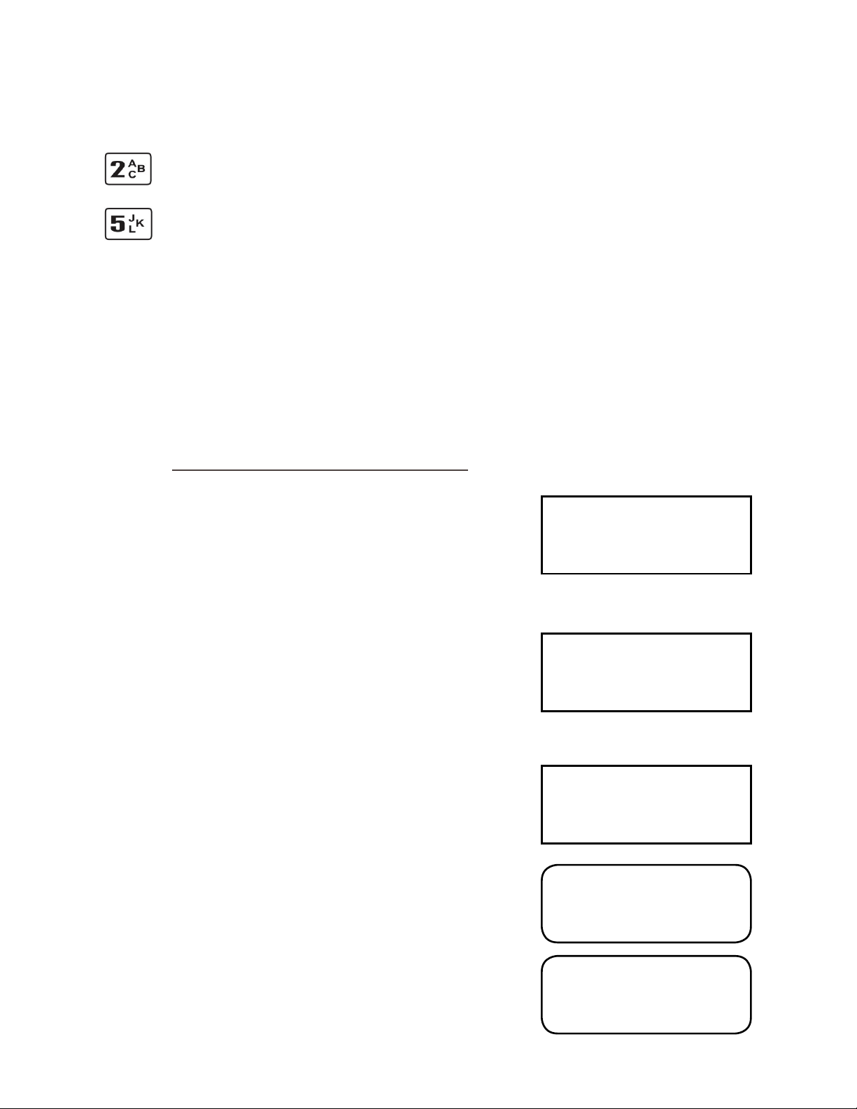
Entering Letters
You may need to enter letters using your terminal. Most numeric buttons have alphabetical
characters allocated to them.
e.g. the number 2 button has A, B and C allocated to it
e.g. the number 5 button has J, K and L allocated to it
To enter a letter press the relevant number button and then the MENU button to scroll through the
letters until you select the character required. To enter the next letter you must select the relevant
number button again. To enter a space press the 0 button followed by the MENU key.
If a mistake is made when entering numbers or letters, press the YELLOW button until the incorrect
numbers or letters have been removed. Then re-key the correct entry.
Once all the numbers or letters have been entered press the GREEN button to accept the entry.
READY
Merchant Number
12345678
SALE
Checking Card
Please Wait...
SALE
Key in Amount:
0.00
and then press ENTER
SALE
Cashback?
Enter=YES Clear=NO
 Loading...