

Page 1

Version May 1999
U
ser's Manual
Version May 99
ELITE 770 *
1
Page 2

Terminal ELITE 770
2
Page 3

Version May 1999
INGENICO
9, quai de Dion Bouton
92816 Puteaux cedex
RCS Nanterre B 317 218 758 - SIRET 317 218 758 00033
Table of contents
I- PRESENTATION OF TH E TERMINAL 5
1- Introduction 5
2- The Terminal 6
3- The connections 6
DIV0510A
4- The Keyboard - Principles of Utilisation 8
5- The Card Reader 9
6- Portable Functioning 9
II - ELITE 770 TECHNICAL OVERVIEW 11
1- Terminal feature 11
2- Display 11
3- Printer 11
4- RS232 Interface 12
5- RS232 Connection 12
6- Modem 13
7- SIM Interfaces 13
8- Technical Specifications 14
III- PROCEDURES OF INSTALLATION 16
1- Configuring Radio Link 16
2- Entering the Date and the Time 17
3- Telephone Network Parameters 18
3
Page 4

Terminal ELITE 770
4- Configuration Receipt 19
5- Option « Table Number » 19
6- Application Software Downloading Procedure 20
IV - SECURITY RECOMMANDATIONS 21
4
Page 5
Version May 1999
I- Presentation of the terminal
1- Introduction
The ELITE 770 is a portable payment terminal. This terminal was created to process all
payments made by magnetic or smart cards.
The ELITE 770 terminal benefits from a modular conception which permits it to treat all cards of
different types using separate corresponding programs. It is therefore important to understand
the manner in which it functions, at the modular and the terminal level.
0
The Modular Level
These functions link up with and correspond to the many different types of cards that the terminal
processes, the most important of which is the principal function of payment.
0 The Terminal Level
There are a certain number of functions that are the concern of a ‘global treatment’ and not of a
particular module. The terminal level is the superior level and is common to all modules. This
level does not depend on the number or the nature of each module.
In its base version the ELITE 770 terminal is equipped with a module
that permits it to process Bank Cards. Your retailer or installer will be
able to give you all the necessary information on all modules on offer
and their installation details.
5
Page 6
Terminal ELITE 770
2- The Terminal
The terminal case contains the following elements :
The portable terminal itself,
• A base.
• The cable that connects the terminal to a telephone line.
• The block sector that connects the terminal to a 115 or 230 volts power point
(depending on the country)
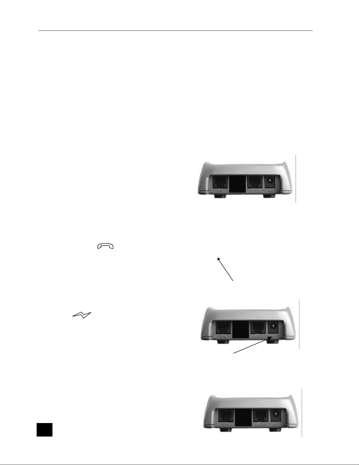
3- The connections
0 Telephonic Connection
The compact telephonic cable connection
that is supplied with the Elite terminal, must
be introduced into the terminal plug, marked
with the symbol . The telephone
connection (RJ11) must be introduced into
the telephone socket in the wall.
.
0 Electrical Connection
The small jack connection to the block sector
is plugged into the connection marked with
the symbol on the terminal. The twin
pronged electrical plug of the block is
connected to an electrical point of 115 or
220 volts (depending the country).
0 Connection with an External Peripheral
Certain peripheral devices such as a check
reader can also be connected.
Telephonic line
Power Supply
6
Page 7

Version May 1999
The ELITE 770 terminal must be powered
off before connecting the cable on the base,
to the RS232 port..
Serial port
7
Page 8

4- The Keyboard - Principles of Utilisation
• The key permits the operator to access the corresponding modular level
functions
• The and keys permit to access to the terminal level functions and
to the system menu
• The key ↑↑ permits a paper feed of a couple of centimetres
• The GREEN key permits the validation of any information read by
or entered into the terminal
• The RED key cancels the occurring command after which, it returns
the terminal to the idle state
• The YELLOW key deletes the last character entered, and is used
in certain cases where an override is requested
• The key marked 00 can only be used for entering amounts ;
more particularly it permits the operator to enter amounts in cents
Version May 1999
8
Page 9

Version May 1999
5- The Card Reader
0 Magnetic Stripe Card
The card can be read either swiped from right to left, or from left to right. The magnetic
track on the card turned on the rear side of the terminal and the card should be swiped
through the track reader freely and without hesitation.
0 Micro Chip Card
Introduce the card horizontally into the apparatus, the micro-chip facing up, as indicated
and leave the card in position for the length of time that it takes to process the
transaction.
6- Portable Functioning
The ELITE 770 terminal is portable ; it includes batteries which permit to make 150
transactions without connection to the base.
A star on the upper right side of the display indicates a correct connection between the
terminal and its base.
A battery lo w is indicated by a message « -BAT- » on the display following by a beep.
The terminal continues to run during about 40 transactions, but batteries need to be
reloaded during at least 14 hours.
In a portable mode, the ELITE 770 terminal enters in a wait state automatically after 20
seconds of inactivity or after hitting the RED key.
The message « -RANGE- » appears on the terminal display when the terminal is
out of range of the base, during a communication establishment. To work properly,
put the terminal nearer the base (about 100 meters in open air, 40 meters inside a
building depending on the environment).
The message « -BUSY- » appears during a connection with the base when an
other terminal is already in communication with this base. The operator must wait
the end of the communication between the base and the other terminal.
The message « -FULL- » appears when the terminal wants to connect a base
which already has the right number of terminal. In this case, switch off the base
during a few seconds, and launch a profile on each terminal (System menu-
9
Page 10

Terminal ELITE 770
configuration) of the network. If the problem persists, switch off the base and call
your maintenance company.
Before the first use of the terminal, batteries must be
loaded during at least 14 hours.
10
Page 11

Version May 1999
II- ELITE 770 TECHNICAL OVERVIEW
1- Terminal feature
The ELITE 770 version has the following features :
• Up to 1Mbyte Battery backed-up RAM with advanced memory protection
• 512 bytes EEPROM
• INTEL compatible 8051 CPU
• Battery backed-up calendar
• Buzzer
• 18 keys keyboard
• Track 2 Card Reader (Optional Track 2 & 3 or 2 & 1)
• ISO 7816 Smart Card Reader
• 1 RS232 port for an ECR connection or external device connection
• Built-in Modem CCITT V22, V22 bis
Automatic tone dialling facility
•
• Short range radio communication with base
• Up to four SIM smart card connectors (Option)
• Short range radio base with RS232 serial communication port
• LAN facilities on a same base (up to 10 terminals)
2- Display
The Display is a 2 lines 16 characters back-light LCD or a large screen graphical
display
3- Printer
The printer includes the following features :
a paper chamber for housing the paper roll
•
• a cutter, above the printer mechanism, allowing the user to cut manually the
receipts
• a push button which activates the Line Feed mechanism and self-test
• a speed of 4 lines per second
11
Page 12

Terminal ELITE 770
4- RS232 Interface
Logic level (RS 232C level) :
• logic level « 0 » : -8V
• logic level « 1 »: +8V
• minimum « 0 » level on input : -3V
• minimum « 1 » level on input : +3V
• maximum current : 10 mA
standard interface :
• rate : 300 to 19200 bauds
• format : 7 to 8 bits
• parity: odd, even, none
• interface: V28
5- RS232 Connection
6
1
12
1 þþ N.U
2 þþ TxCOM1
3 þþ RxCOM1
4 þþ CTS
5 þþ RTS
6 þþ Ground
Page 13

Version May 1999
6- Modem
The Modem fulfils the data exchange function between the system and telephone
network. It is a full-duplex asynchronous modem complying with CCITT V22 & V22 bis
recommendations.
The MODEM is connected (through the base) to the telephone network by a removable
cord f itted with a telephone connector which is plugged into the telephone wall socket.
It is equipped with :
• A computerised electronics with built -in application program and module
self-test
• A line interface for connection to the telephone network
• An automatic tone dialling facility
• A connector for plugging in a removable phone cord, fitted with a 6-contacts
connector or adapter plug (depending on the country)
7- SIM Interfaces
When implemented, access to the optional SIM connectors needs to open the battery
door located at the bottom of the terminal.
13
Page 14

Terminal ELITE 770
0 SIM Installation
• Slide the card holder cover,
• Turn over the cover
• Insert a SIM card into the card holder,
• Shut the cover
• Slide the cover to lock
0 SIM Removal
• Slide the card holder cover,
• Turn over the cover
• Remove SIM card from the card holder,
• Shut the cover
• Slide the cover to lock
8- Technical Specifications
0 Power Supply.
• Power Input Voltage 115 / 230Vac
• Power Input Frequency 50/60Hz
• Power Output 10 Vac 500 mA 6 VA
a b c
∅
5,5
∅
2,5
9,5
14
Page 15

0 Terminal
• Dimensions H x D x W 210 x 92 x 68 mm
Operating Temperature +5oC to +40oC
•
• Humidity 20% to 90% No Condensation
0 Radio communication
• Type Half -duplex
• Bandwidth ISM 433,9 MHz
• Emitting power ≤10 mW (Don’t need license)
Channels 15 (100 kHz between channels)
•
• Range ≈ 100 meters (open air)
≈ 40 meters (typical)
Version May 1999
15
Page 16

Terminal ELITE 770
III- PROCEDURES OF INSTALLATION
After having made the connections previously described, the operator can switch the
terminal on. Before doing this, the operator is obliged to enter all general data at the
terminal level.
1- Configuring Radio Link
IMPORTANT NOTE : The following configuration is not necessary for a
single configuration (one base, one terminal), as it has been carried out
during production.
It is necessary only if you attempt to add a terminal on a previously purchased base.
This procedure, if failed, can provoke malfunction of other terminals connected to
your base. In case you are not sure to carry it out properly, or if it does not work
properly, call your retailer, who has powerful tools to configure both terminals and
base.
The LAN can not support more than 5 terminals without reconfiguring base. In case
you need 6 to 10 terminals on the same base, call your retailer, who is able to
configure properly the base.
• The link between the base and the terminals is coded from the related serial
numbers. This means that both terminals and base must know the serial number
of other components in the LA N.
• The base is able to find terminals identifiers at the first radio connection after
power-on. You don’t need to configure it.
The terminal must be configured in order to know the number of the base where
•
it will have to connect. In the menu « INPUT BASE # » under « SYSTEM
MENU », validate. The terminal then displays « LAN CONFIG. ». Enter the
code 2049, then validate. The terminal displays then the maximum number of
terminals. If your base is a ‘standard’ one, enter 5, then validate, else validate
without modification. The base’s serial number is then displayed. This number
correspond to the number printed on the back of the base. Enter it, followed by
the VAL key.
• Your terminal is now configured. You can test it by printing a configuration
receipt (system menu, configuration), that must indicate the number of terminals
and the base serial number.
• In case the message ‘Absent base ! ‘ is printed, the base serial number is not
correct.
• In case the message « FULL » is displayed, the number of terminals is not
correct, or your base don’t support an other terminal.
16
Page 17

Version May 1999
2- Entering the Date and the Time
In its dormant state the terminal indicates its version of the date and time. The date and
time modification procedure will not be carried out if the date and time are incorrect.
N° DISPLAY/PRINTING ACTION
1 CARD >>>
21/07/99 18 :32
2 SYSTEM MENU
CHANGE DATE TIME
3 DATE : 21/07/99 Enter the current date (character « / »
4 TIME : 18 :32 Enter the current time (character « : »
5 CARD >>>
21/07/99 18 :32
Press the key
Press the GREEN key
is automatically inserted).
Press the GREEN key
is automatically inserted).
Press the GREEN key
17
Page 18

Terminal ELITE 770
3- Telephone Network Parameters
With regard to the following points ; if the value already present in the apparatus is
correct, the value will be validated without having to enter a new one.
N° DISPLAY/PRINTING ACTION
1 CARD >>>
21/07/99 18 :32
2 SYSTEM MENU
CHANGE PAD PAR.
3 SYSTEM MENU
SWBOARD =
(up to 4 char)
4 DWNL = 08 36 06 24 24
(up to 12 char)
5 CARD >>>
21/07/99 18 :32
Press the key and select the function by
or keys
Press the GREEN key
The current value is displayed. If necessary,
enter the value of the switchboard to connect the
terminal to the switch network. Cancel the value
with the RED key in the case of a direct line.
Press the GREEN key
Press the GREEN key
18
Page 19

Version May 1999
d select the function by
key and select the function by
the table number will be requested for each
4- Configuration Receipt
This receipt put together the hardware and the software status of the terminal.
N° DISPLAY/PRINTING ACTION
CARD >>>
1
21/07/99 18 :32
SYSTEM MENU
2
CONFIGURATION
The terminal prints a receipt
3
CARD >>>
4
21/07/99 18 :32
Press the key an
or keys
Press the GREEN key
5- Option « Table Number »
This function is used in a restaurant environment.
N° DISPLAY/PRINTING ACTION
CARD >>>
1
21/07/99 18 :32
SYSTEM MENU
2
OPTIONS
ENTER TABLE N. : 0 The current value is displayed. « 1 » means
3
CARD >>>
4
21/07/99 18 :32
Press the
or keys
Press the GREEN key
payment
19
Page 20

Terminal ELITE 770
or
press the
6- Application Software Downloading Procedure
This function allows the remote downloading of a new software application version. The
terminal call the host which contains the new required version of the application.
N° DISPLAY/PRINTING ACTION
CARD >>>
1
21/07/99 18 :32
SYSTEM MENU
2
DOWNLOAD
DOWNLOAD
3
Confirm ENTER
DOWNLOAD
4
Download ?
DOWNLOAD
5
PABX= ?
DOWNLOAD
6
Code =
DOWNLOAD
7
Tel #
DOWNLOAD
8
DIALING
Press the key and select the function by
keys
Press the GREEN key
Press the GREEN key
Press the GREEN key
If necessary , enter the value of the switchboard to
connect the terminal to the switch network
If necessary, enter the header of the host phone
number and press the GREEN key
Enter the host telephone number and
GREEN key
The terminal attempts to establish a connection to
the host.
After the connection, four possibilities are offered :
ADD, UPDATE, DELETE and END
( for more explanation refer to the download
manual)
20
Page 21

Version May 1999
IV- SECURITY RECOMMANDATIONS
0 0
This terminal has no power switch. The power supply is the only device used to
switch off the terminal. Of this fact the main power must be easily accessible.
1 Guideline of security concerning the Lithium batteries:
• Hold out of reach of the children,
• I n case of ingestion of battery elements, the person involved should seek medical
assistance promptly,
• It is important to respect the polarities `+ ' and`-`,
• Do not attempt to reactivate the batteries by a heat source, by an electric refill or all
other means,
• Do not dispose of batteries in fire,
• Do not disassemble the batteries
1 Guideline of security concerning the batteries nickel Cadmium:
• Hold out of reach of the children
• Do not heat or throw to the fire,
• Do not short-circuit the batteries,
• Do not close up the valves of security (situated under the positive poles),
• Do not use in a hermetic box,
• Use the adapted charger, only in the range of specified temperature,
• Do not manipulate and put back in service if the battery is damaged and/ or if it presents
some liquid flights.
1 Of a general manner:
• A danger of explosion is possible if there is incorrect replacement of the battery.
• Replace the battery with the same equivalent type advise by the constructor.
• Put the used batteries to the rubbish accordingly to the instructions of manufacturer.
00 The equipment has been approved in accordance with Council decision 98/482/EC for panEuropean single terminal connection to the public switched telephone network (PSTN). However,
the approval does not, of itself, give an unconditional assurance of successful operation on every
PSTN network termination point.
In the event of problem, you should contact your equipment supplier in the first instance
21
Page 22

ELITE 770 Terminal
22
Page 23

Version May 1999
23
 Loading...