

Page 1
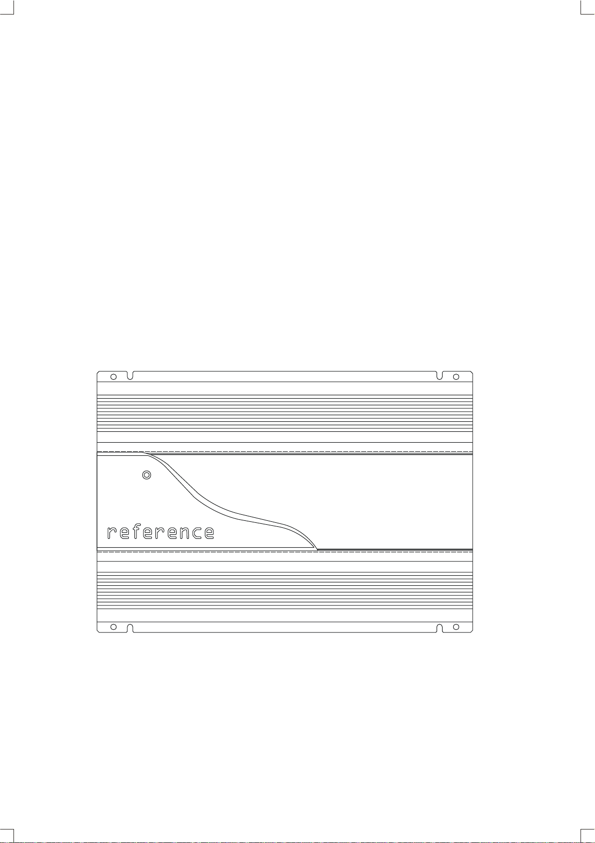
RA 7502
2 CHANNEL
POWER AMPLIFIER
TECHNICAL MANUAL
.infinitysystem.com
www
c 200 harman consumer international
Print in - 10/2000
Infinity
Page 2

2 Channel Power Amplifier
Controls and connections
Specifications .........................................................1
Features .................................................................2
Test Conditions and Notes .......................................2
Controls and Connections ........................................3
Typical System Configuration (Wiring) ........................4
Printed Circuit Boards (Top View)...............................5
Number of Channels . . . . . . . . . . . . . . . . . . . . . .
Power Output max . . . . . . . . . . . . . . . . . . . . . . . .
RMS Bridged Power Output ,4 Ohm . . . . . . . . . . . . . . . . . . . . . ..
RMS Power Output,2 Ohm . . . . . . . . . . . . . . . . . . . . . . . . . .
RMS Power Output,4 Ohm . . . . . . . . . . . . . . . . . . . . . . . . . .
THD@Rated Output. . . .. . . . . . . . . . . . . . . . . . . . . . . . . . . .
SNR (A - weighted) . . . . . . . . . . . . . . . . . . . . . . . . . . . . .
Frequency response . . . . . . . . . . . . . . . . . . . . . . . . . . . . .
Parts Lists......................................................6~7
Block Diagrams...................................................8
Packaging Exploded View.....................................9
Integrated Circuit Diagrams.................................10
Transistor Diagrams......................................11~12
Schematic Diagrams................... ..................13~14
Amplifier Exploded View.....................................15
SPECIFICATIONS
2
300W
220W
2 x 110W
2 x 75W
0.10%
>92dB
10Hz-40kHz
Active crossover(cont.var.) . . . . . . . . . . . . . . . . .
Crossover settings . . . . . . . . . . . . . . . . . . . . .
Crossover slope . . . . . . . . . . . . . . . . . . . . . . .
Input sensitivity. . . . . . . . . . .
. . . . . . . . . . . . . . .
Bass Boost . . . . . . . . . . . . . . . . . . . .
External Dimensions (Inches)
Length . . . . . . . . . . . . . . . . . . . . . . . . . . .
Width . . . . . . . . . . . . . . . . . . . . . . . . . . .
Depth . . . . . . . . . . . . . . . . . . . . . . . . . . .
External Dimensions (mms)
Length . . . . . . . . . . . . . . . . . . . . . . . . . . .
Width . . . . . . . . . . . . . . . . . . . . . . . . . . .
Depth . . . . . . . . . . . . . . . . . . . . . . . . . . .
30-320Hz
LP/HP/OFF
12dB/oct
100mV-4V
+6dB@45Hz
13 3/8
9 3/8
2 1/16
340
238
52
1
Page 3

2 Channel Power Amplifier
Features
RCA-jacks, Speaker-and power terminals gold-plated
2 ohm stability(stereo mode)
Bridging capability(min.4 ohm)
Tri-mode operation(min.4 ohm)
Protection circuitry thermal-and electrical overload.short-circuit.DC-offset
HPF variable high pass filter(HPF)30-320Hz.12dB/oct.
LPF variable low pass filter(LPF)30-320Hz.12dB/oct.
+6dB(at 45Hz)Bass boost
Test Conditions and Notes
All tests to be done, unless otherwise specified, from 30Hz to 320Hz at 14.4V DC into 2 ohm loads and adjust
the units gain so that with a .100 volt input signal the unit is at its maximum rated output. All measurements
will be done using an Audio precision system one and the supply voltage.
An A+ line voltage of 14.4V DC shall be applied to the unit under test for all measurements unless otherwise
specified. The voltage applied to the unit shall be measured at the power connection on the Amplifier.
Signal Source
Unless otherwise specified, all tests shall be conducted with the Audio Signal Generator output configured to
be balanced, less than or equal to 50 ohm source impedance, and floating. The signal source "GND" shall be
connected to the Amplifier PWR GND at the Amplifier.
Output Load
Unless otherwise specified, all tests shall be conducted with 2 ohm resistive loads having less than 0.1%
reactive components at any frequency below 1Kz. Each resistor shall have a value that remains within 0.1%
while dissipating the rated output of the unit under test.
Power Indicator LED steadily illuminates for normal operation.
2
Page 4
2 Channel Power Amplifier
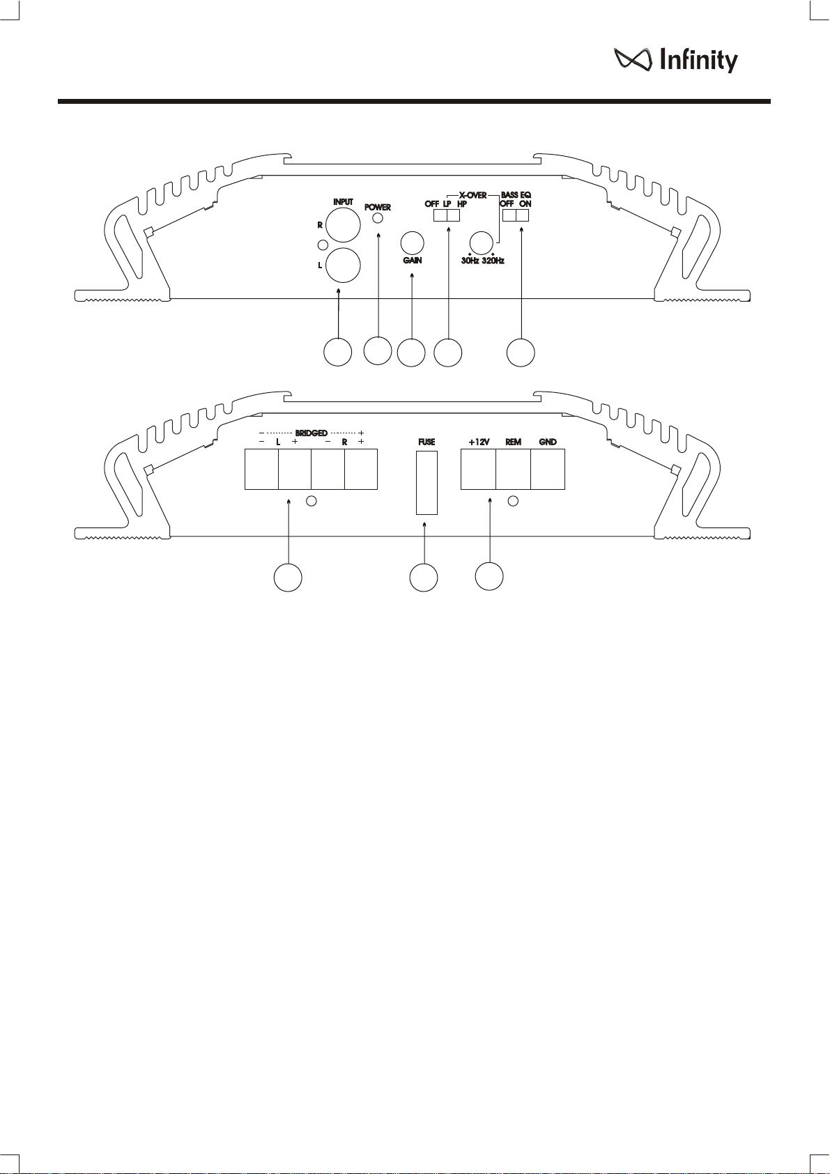
Controls and Connections
2
11
3
4
5
8
Controls and Connections
1. Low INPUT (RCA JACK TYPE)
- Connection to line of level output from the
source unint
2. Power Indicator
3. Input-sensitivity level coltrol
4. Low/High pass filter which caN be set at
any frequenccy between 30Hz and 320Hz(adjustable)
7
5. +6dB(at45Hz)Bass boost
6.Power Connector-Connection +12V+ for,
GND and REM in or out.
7.Fuse - 32V25A attached type
8. Output Connector - connect a wire between
the output terminal on the amp and Speakers
(each channels)
6
3
Page 5

2 Channel Power Amplifier
Power
Antenna
Antenna Input
Cassette/Receiver
Power Supply
Wires
Typical System Configuration
Cassette/CD Tuner
(Head Unit)
CD Player or Changer
Power
Antenna
Relay
Power Supply
Antenna Motor Ground
Remote Antenna
Remote On/Off
Black - Power Ground
Ignition
Switch
Fuse
Fuse
Black Power
Red - Main +12V
Line
Level
Input
Remote On/Off
60 Amp (Not Included)
Fuse
Power Ground
Infinity
Main +12V
Amplifier
Power
Connection
Vehicle Battery
Chassis Ground
Speakers
4
Page 6

2 Channel Power Amplifier
Printed Circuit Board (Top View)
Q130
Q43
Q44
Q54
Q53
Q125
A1694
C3200GR
C4467
Q115
RA7502
PAM42301
D3
YG225D2
YG225D2
D4
50KC
TH1
50N06
50N06
50N06
50N06
KLG124-E
DJB-552S
D81
1K
J2
10PC204
R214 10K
15P
10KF
C104
R109
R141
1.2K
C143
B631K
100P
Q124
R152
0.1/3W
R153
1.5K
R151
0.1/3W
C51
470/50V
470/50V
C61
22
R43
R52
1K
22
R44
22
R54
R42
1K
22
R53
C4
C18
C140
2.7K
R150
220
R135
3.9K
Q114
L2
R71
2200/25V"RX"
2200/25V"RX"
C1027Y
Q123
47
R144
473(M)
R145
R134
47
Q113
A1023Y
100PC142
D600K
1.2K
R131
R172
18K
33P
R171
C17
6.8K/0.5W
R28
R27
6.8K/0.5W
C52
C53
473P
CL-500
473P
C63
L3
CL-500
C62
222(M)
C41
100/2W
T1
37PHI 6T(0.7X9):14T(0.7X4)
CL-300
1N5404
D1
104P
L1
105(M)"TL"
C9
1K
R81
1.8K/1W
180KF
R208
110KF
R108
220PC133
910
C152 100/16V
104P
C10
R101
2.2/50V
A1266GR
C3198GR
A1266GR
C3198GR
R2
C3
R201
NJM2068LD
U101
473PC121
C130
Q121
Q111
Q112
C132
R3
C27
R185 680
220/16V
2200/50V
10/0.5W
C103
R127 22KF
5.6KF
2200/50V
4.7K
473P
6.8K
R5
100/16V
A1023Y
10/16V
C3198GR
C28
220/16V
Q1
C203
10/16V
VR101
102P C201
102P C101
10/16V
10/16V
C106
15.2KF
R113
R207
15KF
22k
R209
473P
C221
R107 15.2KF
KIA4559S
R114
10K
473P
U103
C222
473PC122
R130
R142 22
R132 22
R143 22 Q122
22
R133
R182
R184
5.6K
5.6K
R181
680
C131
470/16V
220/2W
R180
PR1504
D53
D31
1SS133
A1266GR
Q33
220/0.25W
A1266GR
R41
Q23
220/0.25W
A1266GR
C11
R12
10K
2.2K
R8
430K
10/16V
4.7K
R1
Q2
10.5KF
R6
4.7KF
R7
43K
R9
JSS2308
SW101
510
R206
20kB
510
R106
10/16V
C206
R117
R116
C109
10K
5.1K
47P
R115
C110
104(M)
R119
6.8K
R118
C209
KIA4559S
47P
10K
R215
6.8K
U104
R218
10K
R217
473P
C123
R213 22k
5.6KF
R230
Q221
22
R242
R23222
R24322
R23322
C232
5.6K
R282
5.6K
220/16V
R283
220/16V
R281
680
680R284
C231
C182
C181
470/16V
Q141
1N4744
220/2W
D102 1N4744
D101
R186
C57
C67
2.2/50
2.2/50V
PR1504
PR1504
PR1504
D51
D54
D52
C108
C16
15K
47/25V
R34
15K
R51
A1268GR
Q3
C22
D21 1SS133
104P
C3198BL
Q21
10K
R13
Q11
100/16V
C8
R14
10K
A1266GR
R11
Q12
C6
C7
100/16V
C13
100/16V
TL494
104P
U11
D2
1N4004
10K
5.1K
C111
R216
C230
220PC233
R227
22KF
Q211
Q222
910
R272
100/16V
C252
C151
100P
C3200GR
10K
R154
1SS133
100P
C3200GR
C3198GR
C3198GR
220/16V
68KR26
C12
102(M)C21
C223
5.1K
104(M)
2.2/50V
A1266GR
C3198GR
A1266GR
C3198GR
SW102
JSS2208
1K
R278
R275
50KC
VR102
C224
104(M)
Q212
D151
C251
Q241
R254 10K
D251 1SS133
Q27
Q25
R35
R16 680
R33 33K
R32 22K
C15 10/25V
R31 1K
D11 1SS133
R15 10
R22 24K
R10 27K
C14 47/16V
4.7/0.5W
473P
R17010K
R2195.1K
KIA4559S
C210
U105
104(M)
104M)C211
473PC124
C162
Q223
C1027Y
100P
C243
1.2K
R241
47
R244
220
47
R234
A1023Y
Q213
100P
C242
1.2K
Q214
R231
33P
C1
18K
R271
R36
C33
C32
C31
W1
R263
56K
56K
R163
R164
680/2W
104(M)
C161
R165
43K
10K
C260
47P
R270
R269
10K
1K
R268
183(M)
C263
KIA4559S
680K
C262
104(M)
R273
10K
R274
U106
R178
1K
43K
47P C160
KIA4559S
Q224
C240 473(M)
R235
R265
U107
183(M)
10K
473PC125
R253
R264
680/2W
4.7/0.5W
R175
473PC225 473P
R173
680K
C163
R174
Q225
A1694
R252
0.1/3W
C3200GR
Q230
C4467
1.5K
Q215
R251
0.1/3W
R1681K
R169 10K
B631K
2.7K
R245
R250
3.9K
D600K
10K
104P
104P
104P
104(M)
C261
TMN006-00
25A
F1
TMN009-00
5
Page 7

2 Channel Power Amplifier
Ra7502 Parts List
REF. NO
PART NO.
DESCRIPTION
Main PCB, Preamp, Crossover, Power Supply and Power
Amplifier
F.E.T
Q43,44,53,54
5122990004000
FQP50N06
TRANSISTOR
Q123,223
Q01,113,213
Q2,25,27,111,112
Q211,212
Q21
Q141,241
Q3 5105190126800
Q11,12,23,24,121 5105190126600
Q122,221,222
Q115,215
Q125,225
Q114,214
Q124,224
Q130,230
5105190102700
5105190102300
5105190319801
5105190319800
5105190320001
5105030446700
5105020169400
5105196000000
5105190063100
5105190320001
KTC1027Y
KTA1023Y
KTC3198GR
KTC3198BL
KTC3200GR
KTA1268GR
KTA1266GR
S2C4467
S2A1694
KTD600K
KTB631K
KTC3200GR
DIODE
D11,21,31,151,251
D2
D51,52,53,54
D101,102
D1
D3,4
LED81
5110021414800
5110021400400
5110180150400
5110021474400
5110031540400
5110A00000011
5110150012400
1SS133(1N4148)
1N4004
PR 1504
1N4744
1N5404
YG225D2
KLG124-E
RESISTOR
R7
R130,230
R109
R6
R209
R107,207
R127,227
R108
R208
R15
R43,44,53,54,132
R133,142,143,232
R233,242,243
R134,144,234,244
R150,250
R106,206
R16,181,185,281
R284
R172,272
R31,42,52,101,168
R178,201,268,278
R131,141,231,241
R153,253
R11
R145,245
R137,237,337,437
5115022047203
5115022056203
5115022105201
5115022105201
5115022015303
5115022015303
5115022022303
5115022110303
5115022180304
5115022010000
5115022022000
5115022047000
5115022220000
5115022510000
5115022047000
5115022910000
5115022001300
5115022012200
5115022015200
5115022022200
5115022027200
5115022039200
METAL FILE 1/5WF 4.7K OHM
METAL FILE 1/5WF 5.6K OHM
METAL FILE 1/5WF 10K OHM
METAL FILE 1/5WF 10.5K OHM
METAL FILE 1/5WF 15K OHM
METAL FILE 1/5WF 15.2K OHM
METAL FILE 1/5WF 22K OHM
METAL FILE 1/5WF 110K OHM
METAL FILE 1/5WF 180K OHM
CARBON FILE 1/5WJ 10 OHM
CARBON FILE 1/5WJ 22 OHM
CARBON FILE 1/5WJ 47 OHM
CARBON FILE 1/5WJ 220 OHM
CARBON FILE 1/5WJ 510 OHM
CARBON FILE 1/5WJ 680 OHM
CARBON FILE 1/5WJ 910OHM
CARBON FILE 1/5WJ 1K OHM
CARBON FILE 1/5WJ1.2k OHM
CARBON FILE 1/5WJ 1.5K OHM
CARBON FILE 1/5WJ 2.2K OHM
CARBON FILE 1/5WJ 2.7K OHM
CARBON FILE 1/5WJ 3.9K OHM
REF. NO
R1,2
R116,119,216,219
R182,184,282,283
R5,118,218
R12,13,14,36,114
4
2
3
7
1
2
1
8
2
2
2
2
2
5
1
4
2
1
2
1
1
2
1
1
1
2
2
1
1
1
12
4
2
2
5
2
9
4
2
1
2
2
R115,117,154,169
R170,174,214,215
R217,254,269,270
R274
R34,35
R172,271
R32,113,213
R22
R10
R33
R9,175,275
R163,263
R26
R8
R173,273
R41,51
R165,265
R3
R27,28
R81
R71
R180,186
R164,264
R151,152,251,252
CAPACITOR
C204
C104
C1,17
C109,160,209,260
C1142,143,242,243
C151,251
C133,233
C101,201
C28,53,63,121,123
C124,125,221,222
C223,224,225
C3,7,9,22,31,32,33
C57,67,130,230
C6,27,103,203,206
C15
C14
C16
C8,11,12,13,152,252
C108,131,132,231
C232
C21
C41
C163,263
C140,240
C110,111,161,162
C210,211,261,262
C10
C181,182
C51,61
C4,18
PART NO.
5115022047200
5115022051200
5115022056200
5115022068200
5115022010300
5115022015300
5115022018300
5115022022300
5115022024300
5115022027300
5115022033300
5115022043300
5115022056300
5115022068300
5115022430300
5115022680000
5115023220000
5115024047801
5115024010000
5115024068200
5115036018200
5115036100000
5115036220000
5115036680000
5115047001802
5113037010000
5113A00000067
5113A00000079
5113A00000082
5113037100000
5113A00000095
5113A00000087
5113A00000103
5113A00000089
5112327022800
5112324010000
5112325010000
5112324047000
5112325047000
5112324100000
5112324220000
5114507001A00
5114507022B00
5114507018A00
5114507047A01
5114A00000002
5114808105000
5112324470000
5112327470000
5112225022200
DESCRIPTIONQ'TY
CARBON FILE 1/5WJ 4.7K OHM
CARBON FILE 1/5WJ 5.1K OHM
CARBON FILE 1/5WJ 5.6K OHM
CARBON FILE 1/5WJ 6.8K OHM
CARBON FILE 1/5WJ 10K OHM
CARBON FILE 1/5WJ 15K OHM
CARBON FILE 1/5WJ 18K OHM
CARBON FILE 1/5WJ 22K OHM
CARBON FILE 1/5WJ 24K OHM
CARBON FILE 1/5WJ 27K OHM
CARBON FILE 1/5WJ 33K OHM
CARBON FILE 1/5WJ 43K OHM
CARBON FILE 1/5WJ 56K OHM
CARBON FILE 1/5WJ 68K OHM
CARBON FILE 1/5WJ 430K OHM
CARBON FILE 1/5WJ 680K OHM
CARBON FILE 1/4WJ 220K OHM
CARBON FILE 1/2WJ 4.7 OHM
CARBON FILE 1/2WJ 10 OHM
CARBON FILE 1/2WJ 6.8 OHM
METAL FILM 2WJ 1.8K OHM
METAL FILM 2WJ 100 OHM
METAL FILM 2WJ 220OHM
METAL FILM 2WJ 680OHM
WIRE WOUND 3WJ 0.1OHM
CERAMIC DISK 50V"NOP" 10pF
CERAMIC DISK 50V"NOP" 15pF
CERAMIC DISK 50V"NOP" 33pF
CERAMIC DISK 50V"NOP" 47pF
CERAMIC DISK 50V"NOP" 100pF
CERAMIC DISK 50V 220pF
CERAMIC DISK 50V 102pF
CERAMIC DISK 50V 473pF
CERAMIC DISK 50V 104pF
ELECTROLYTIC"SMS" 2.2 §Þ/50V
ELECTROLYTIC"SMS" 10 §Þ/16V
ELECTROLYTIC"SMS" 10 §Þ/25V
ELECTROLYTIC"SMS" 47 §Þ/16V
ELECTROLYTIC"SMS" 47 §Þ/25V
ELECTROLYTIC"SMS" 100 §Þ/16V
ELECTROLYTIC"SMS" 220 §Þ/16V
MYLAR 5% 100V 0.002 §Þ
MYLAR 5% 100V 0.0022 §Þ
MYLAR 5% 100V 0.018 §Þ
MYLAR 5% 100V 0.047 §Þ
MYLAR 5% 100V 0.1 §Þ
MYLAR 5% 63V "TL" 1 §Þ
ELECTROLYTIC"SMS"
ELECTROLYTIC"SMS"
ELECTROLYTIC"RX" 2200 §Þ/25V 2
470§Þ/16V
470§Þ/50V
Q'TY
2
4
4
3
18
2
2
3
1
1
1
3
2
1
1
2
2
2
1
2
1
1
2
2
4
1
1
2
4
6
2
2
13
7
4
6
1
1
1
6
5
1
1
2
2
8
1
2
2
6
Page 8

2 Channel Power Amplifier
Ra7502 Parts List
REF. NO
C52,62
IC
U11
U101
U103,104,105,106
U107
VOLUME
Vr101
Vr102
INDUCTOR
L1
L2,3
JUMPER
JMP4
JMP37,39,41,53,60
JMP62,63,68,69,71
JMP72,75,91
JMP9,29,40,57,59
JMP64,70,92,100
JMP13,17,19,20,24
JMP31,34,35,36,42
JMP46,47,48,49,81
JMP84,89,90,94
JMP5,6,15,23,25,27
JMP28,33,43,45,61
JMP86,87,88,101
JMP1,2,7,8,12,18,32
JMP51,54,55,65,77
JMP83,95
JMP10,14,21,22,26
JMP30,44,56,58,66
JMP78,79,80,82,98
JMP99
JMP3,11,16,38,50
JMP52,73,74,76,85
JMP93,96,97
Th1
T1
J2
W1
RCA0.1,02
F1
1SET+1ASS'Y
Sw101
Sw102
T1
FET,DIODE
TR
D81/Q130,230/TH01
J1
J3
PART NO.
5112287022200
5104010049401
5104020206802
5104020455902
5117040020399
5117040008399
5124020030000
5124030050000
5148000000600
5148000000705
5148000001000
5148000001205
5148000001500
5148000001705
5148000002000
5148000000500
5111030535000
5126A00000006
5139A00000043
5129220600000
5139030007999
5131000960400
53M5FU0000500
5108050230800
5108050220800
531SA05003000
53PSA05003000
53MOPS0005400
5149000701001
5138040000600
5138A09000001
DESCRIPTION
ELECTROLYTIC"SHL" 220 §Þ/50V
P.W.MIC TL494CN
DUAL OP AMP NJM2068LD
DUAL OP AMP KIA4559S
V-12-CLG0266N
V-12-CLG0252NA
CL-300
CL-500
"0"OHM JUMPER 6m/m
"0"OHM JUMPER 7.5m/m
"0"OHM JUMPER 10m/m
"0"OHM JUMPER 12.5m/m
"0"OHM JUMPER 15m/m
"0"OHM JUMPER 17.5m/m
"0"OHM JUMPER 20m/m
"0"OHM JUMPER 5m/m
NTC RESISTOR 50K FTD5-350
6T(0.7X9):14T(0.7X4)
GLD PLATED DJB-552S
1007 AWG #22, BK 60m/m
GOLD PLATED DJB-562
P.C.B TYPE Y-WH-9402P
32V/25A
SLIDE SWITCH JSS2308A
SLIDE SWITCH JSS2208A
29PHI
10X8X0.5t
15X6X0.5t
07PHI 10m/m
GOLD PLATED,3P TMN006-00
GOLD PLATED,4P TMN009-00
REF. NO
2
1
1
5
1
1
1
2
1
13
9
19
26
14
16
13
1
1
1
1
2
1
2
1
1
1
6
4
8
1
1
MECHANICAL
MAIN HEAT SINK
FRONT PANEL
REAR PANEL
BOTTOM COVER
PLEXI GLASS
TR BRACKET(A)
TR BRACKET(B)
TR BRACKET(C)
TR BRACKET(D)
TR BRACKET CUSHION(A)
TR BRACKET CUSHION(B)
RUBBER CUSHION(A)
RUBBER CUSHION(B)
RUBBER CUSHION(C)
EVA CUSHION
SILICON PAD
PCB SUPPORT
OPEN LUG(A)
OPEN LUG(B)
SCREW
SCREW
SCREW
SCREW
SCREW
SCREW
SCREW
SCREW
SCREW
SCREW
SWITCH DECAL
VOLUME KNOB
INNER PAD
GIFT BOX
CARTON BOX
POLY BAG(A)
POLY BAG(B)
POLY BAG(C)
MANUAL
SER NO
MADE IN KOREA LABEL
SILICAGEL
SCOTCH TAPE
OPP TAPE
QC LABER
BRAND STICKER
CE LABEL
PART NO.
MAHSHC70341 AL/EXTRUDING L=340.0mm
MAFPHC63411
MARPHC63421
MABCHC70361
MANPHC63010
MABR0346280
MABR0346290
MABR0341160
MABR0341170
MOCU0241271
MOCU0248661
M0CU0141330
M0CU0141670
M0CU0119490
M0CU0618210
MASP0219010
MASU0517190
MAOL0100010
MAOL0100020
MNSC0423006
MNSC0423005
MNSC0423008
MNSC0433008
MNSC0074008
MNSC0423015
MNSC0333006
MNSC0524020
MNSC0034016
MOSD0340170
MAKB0140290
MOIN0470441
MAGB0663880
MACB0263890
MAPB0120970
MAPB0116610
MAPB01410110
MDMAHC00040
MDLA0218970
MDLA0219050
MOSG0117680
MOTA0118960
MOTA0218880
MOLA0319100
MOLA0419090
MDLA0219060
DESCRIPTIONQ'TY
EGI 1.0t
EGI 1.0t
EGI 1.0t
ACRYL
SBHG 50.0x22.5x2.0t
SBHG 50.0x25.5x2.0t
SBHG 110.0x22.5x2.0t
SBHG 110.0x25.5x2.0t
FIBER 50.0x22.0x1.0t
FIBER 110.0x22.0x1.0t
RUBBER 10.0x20.0x1.6t
RUBBER PHI12.0xPHI15.0x2.0t
RUBBER 10.0x20.0x2.0t
EVA 8.0x120.0x2.0t
(Sp1000) 23.0x0.3t
BSBM PHI6.0(ГЦ´лАьАе 11.9mm)
2.5SQ
5.5SQ
STT2 BH 3x6 NI
STT2 BH 3x5 NI
STT2 BH 3x8 NI
STT1 PH 2x6 NI
SMT 4x8 NI(STAR)
STT2 BH 3x15 NI
STT3 PH 3x6 NI
STT1 BH 4x20 NI
SMP BH 4x16 NI
FELT 12.0x7.0x0.3t
ABS/BK
SW#1 270.0x76.0x95.0
SW#1 445.0x275.0x100.0
DW#2 460.0x430.0x300.0
VINYL 360.0x500.0x0.1t
VINYL 260.0x350.0x0.03t
VINYL 100.0x80.0x0.03t
ART PAPER
ART PAPER
ART PAPER
3g
20mm
BLUE COLOR
ART PAPER
À¯Æ÷Áö(lmfinity)
ART PAPER
Q'TY
1
1
1
1
1
2
2
1
1
2
1
1
4
2
2
250mm
2
5
2
4
1
3
1
1
1
2
4
4
6
2
2
2
1
1/4
1
1
1
1
4
1
1
20Cm
3.5m
1
1
1
7
Page 9

2 Channel Power Amplifier
Block Diagram
OUTPUT STAGE
SWITCH
CHANNELS 1+2
Ra7502
SWITCH
LPF ( 32 ~ 320Hz )
Input Amp
BASS BOOST( @45Hz : +6dB )
FULL
HPF ( 32 ~ 320Hz )
VOLUME
Block Diagram
INPUT
8
Page 10

2 Channel Power Amplifier
Packaging Exploded View
11
10
12
14
13
4
6
MANUAL
infinity
15
3
16
4
2
1
5
PART NAMENO
01
POLY BAG(A)
02
POLY BAG(B)
POLY BAG(C)
03
INNER PAD
04
05
GIFT BOX
CARTON BOX
06
07
08
09
*PACKING PART LIST*
MA-PB-01-2097-0
MA-PB-01-1661-0
MA-PB-01-4101-0
MO-IN-04-7044-1
MA-GB-06-6388-0
MA-CB-02-6389-0
DESCRIPTION Q'TYPART NO.
VINYL,360.0x500.0x0.1t
VINYL,260.0x350.0x0.03t
VINYL,100.0x80.0x0.03t
SW#1 270.0x76.0x95.0
SW#1 445.0x275.0x100.0
DW#2 460.0x430.0x300.0
*ACCESSORY PART LIST*
MODEL
1
1
1
2
Ra7502
1
1
PART NAMENO
10
RUBBER RING
11
SCREW
FUSE
12
BRAND STICKER
13
MANUAL
14
OPEN LUG(A)
15
16
OPEN LUG(B)
PART NO. Q'TY
MO-CU-01-4167-0
MB-SC-05-2-40-20
MD-LA-04-1909-0
MD-LA-HC-0004-0
MA-OL-01-0001-0
MA-OL-01-0002-0
17
DESCRIPTION
RUBBER 12.0xRUBBER 5.0x2.0t
STT1 BH 4x20 NI
25A
2.5SQ
5.5SQ
MODEL
4
4
1
1
1
Ra7502
5
2
9
Page 11

2 Channel Power Amplifier
U11 (TL494CN) P.W.M IC
DEAD TIME
CONTROL
Integrated Circuit Diagrams
U101 (NJM2068D)
-DUAL OP AMP
A
-
1
2
+
3
45
B
+
-
6
7
8
10
Page 12

2 Channel Power Amplifier
C
B
E
Transistor Diagrams
E
C
B
C
E
C
B
B
C
E
B
* KTC3198GR *
Q2,25,27,111,112,211,212
G
* KTA1266GR *
Q11,12,23,33
Q121,122,221,222
* KTC1027Y *
Q123,223
E
E
C
S
D
DD
B
C
GG
*FQP50N06
Q43,44,53,54
B
SS
E
* KTA1023Y *
Q1,113,213
11
Page 13

2 Channel Power Amplifier
E
C
B
Transistor Diagrams
Transistor Diagrams
C
B
C
B
C
B
C
E
C
E
* KTC3198BL *
Q21
* KTC3200GR *
Q141,241,130,230
E
* KTA1268GR *
Q3
B
*2SA1694 *
Q125,225
B
E
E
* 2SA4467*
Q115,215
K
* YG225D2 *
D3,4
D
AK
E
B
* KTD600K *
Q114,214
C
B
C
E
E
B
C
B
C
E
*KTB631K *
Q124,224
12
 Loading...