

Page 1
Limited Warranty Statement
Infinity warrants this product to be free against defects in materials and
workmanship as follows:
Labor: For a period of two years from date of purchase, if this product
is determined by Infinity to be defective, Infinity will repair and/or replace the product with a new or rebuilt unit or repair at no charge. After
the warranty period, you must pay for all labor and parts charges. Customer to ship the radio pre-paid via UPS ground to Infinity for evaluation. Infinity then will credit the UPS costs at its sole option. If the radio
is found to be defective under warranty, Infinity will repair/exchange
per the above policy, sending the unit back freight prepaid to Customer. If found to be a customer caused problem or abused and outside of above warranty, customer to pay for freight charges to and
from factory plus repair charges at current published repair rates.
Parts: If a warranty issue, Infinity to supply at no charge, new or rebuilt
replacements for defective parts for a period of two years. After the
warranty, standard repair or replacement rates apply.
SERVICE: To obtain warranty service, you must communicate with
Infinity directly, and then once an RMA Return Materials Authorization
Number is received, to ship it back in its original carton, or in packaging offering an equal degree of protection, to Infinity, freight prepaid
with insurance.
This warranty does not cover the battery which has a one year pro-
rated warranty, nor does it cover customer instruction, installation, setup, programming, adjustments or signal reception or transmission.
This warranty does not cover any units which have been previously
altered, repaired, or serviced by anyone other than Infinity or used with
accessories not approved by Infinity. This warranty does not cover
cosmetic damage or damage due to acts of god, accident, misuse,
negligence, or modification to any part of the product
This warranty does not cover products sold AS-IS or with FAULTS.
No particular merchantability of this product is implied or stated.
Proof of purchase in form of a bill of sale or receipted invoice, evi-
dence that the unit is within the warranty period and must be presented to obtain warranty service. Warranty is offered only if a WARRANTY REGISTRATION CARD has been filled out and sent to Infinity,
either by Mail or Email, with 15 days of purchase. This warranty is invalid if the factory serial number applied has been altered or removed
from the Product. Re-Sellers may have additional Warranty State-
ments
REPAIR OR REPLACEMENT AS PROVIDED UNDER THIS WARRANTY
IS THE EXCLUSIVE REMEDY OF THE CONSUMER. INFINITY SHALL
NOT BE LIABLE FOR ANY INCIDENTAL OR CONSEQUENTIAL DAMMAGES FOR BREACH OF ANY EXPRESS OR IMPLIED WARRANTY
ON THIS PRODUCT EXCEPT TO THE EXTENT PROHIBITED BY APPLICABLE LAW. ANY IMPLIED WARRANTY OR MERCHANTABILITY OR
FITNESS FOR A PARTICUAL PURPOSE ON THIS PRODUCT IS NOT
MADE OR IMPLIED BY INFINITY.
40
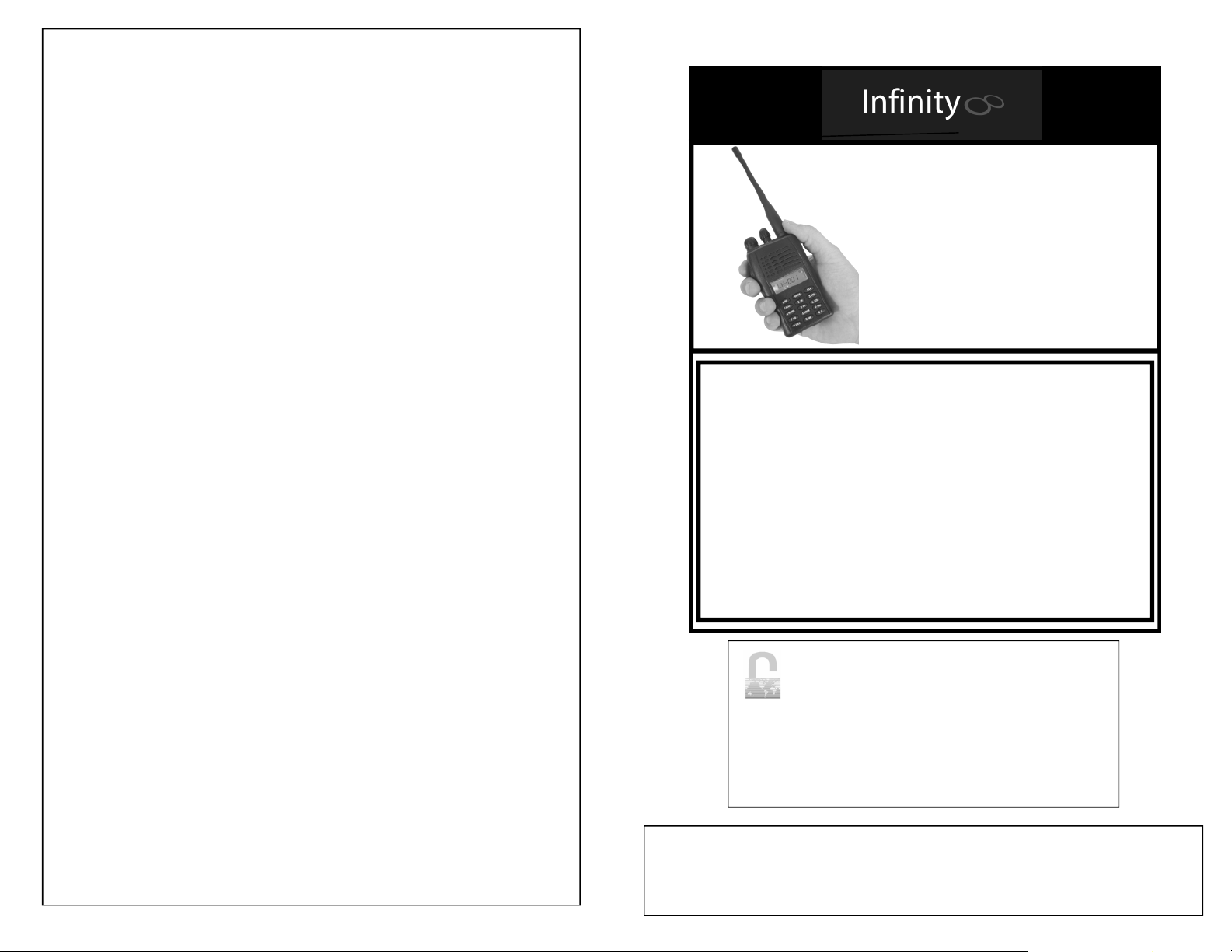
P1000/1010/1045
Standard and P Series
VHF or UHF
User’s Manual
Note: Pager function is programmed only via programming
s/w. Requires additional programming software and cable.
WARNING!
Read the instruction manual completely before use.
-Install the antenna first and then the battery as
pictured in the manual.
-Charge the battery 14-24 hrs before use even if
the green LED on the charger is present, this to
condition the battery. DO NOT OVERCHARGE!
-DO NOT install the battery or use the radio with
out the proper antenna attached.
Failure to perform these steps may damage the
radio and void the warranty. Warranty card needs to
be returned for warranty to be validated.
Kirmuss & Associates
Worldwide Technologies Direct
Infinity Advanced Technologies
1340 West 43rd Drive, Unit 11
Golden, Colorado, USA 80403
tel: 303 263 6353 fax: 303 862 7170
Rev08-04-01
© 2005-2008 Specifications subject to change without notice. Failure to read and following the guidelines established in the manual may void warranty. Restricted to Public
Safety, Fire/EMS use. License to operate is required. Customer is solely responsible for
full compliance with local,stateandfederal laws regarding productusage. Tampering or
modifying unit voids FCC Approval and Warranty.
Page 2
To our Valued Customers:
Thank-you for purchasing an INFINITY two way portable transceiver.
Designed in the USA, built in Hong Kong, this robust, compact, easy to
use radio incorporates the latest technologies, providing reliable performance at an unprecedented low cost. Before operating this radio,
please read this manual carefully. Failure to do so may void warranty.
RADIO FREQUENCY ENERGY SAFETY INFORMATION
This transceiver has been tested an complies with both national and inter-
national standards in regards to Radio Frequency (RF) energy emitted and
guidelines regarding human exposure to RF energy. The radio complies
with FCC and IEEE guidelines for occupational use/controlled RF expo-
sure environments, where duty talk cycles should be limited to 50% talk,
50% listen based on recommendations by the National Council on radia-
tion Protection and Measurement as well as the American National Stan-
dards Institute.
Reference:
FCC OET Bulletin 65, Edition 97-01 Supplement C;
47 CFR 1.1307; 1.1310 and 2.1093
ANSI C95.1.1992
ANSI C95.3.1992
Ministry of Health Canada Safety Code 6
Controlling your exposure to RF energy
To control your exposure to RF and comply with the maximum exposure limits for
occupational/controlled environments, follow these guidelines:
1) Do not talk (transmit) on the radio more than the rated transmit duty cycle. This is
important because the radio radiates more energy when it is transmitting than
when it is receiving.
2) When listing and talking on the radio, hold it upright in front of your face so that it
is at least one inch (2.5 cm) away from any part of your face. Keeping the radio at
the recommended distance is important because exposure to RF decreases
rapidly the further away the antenna is from your body
2
Once configured to send out a Page:
1. Select the channel to the Group or Team or Members that you wish to Page by using the channel
selector.
NOTE: As there are 128 channels available for programming,
we suggest that all channels that will be used to send out a
page could be entered and programmed as well as identified
separately as such. Ex: Channel 30 corresponds to FDPAGE
(as seen on the LCD screen for Fire Dept.); Channel 31 corresponds to EMS PG. (for EMS Members). Then perhaps program in Channel positions 1 and 2 these channels with std
CTCSS PL tones and use without page feature. (Calling them
FIRE and EMS, using them for regular radio traffic)
As a programming consideration, if this radio is to be used to
receive traffic from responders answering the page sent out by
the user of this radio, these PASGE OUT channel should be set
NOT TO DECODE or RECEIVE any pages, this so that the User
(in this case Chief) may hear the responders reply to the message or information sent.
>If this is the case, then a separate DECODE/Receive channel
should then be set up to act as a paging receiver for the user to
receive pages from dispatch or others. That channel in turn will
not be set up to ENCODE or send out a page.
Ex. Channel 40 corresponds to FDPGRX (as seen on the LCD
Screen); Channel 41 corresponds to EMSPRX
2. To send out a Page and Message:
Press and hold down the Orange Button
until you hear a “Beep” from the Radio’s
speaker.
With the Orange Button being held down, both the
RED LED atop the radio and the RF Power Bar meter
on the lower part of the LCD will illuminate indicating
that your radio is transmitting.
When the “Beep” is heard, the transmitter will shut down. The
RED TX LED on the top of the radio and the RF Power Meter on
the LCD will turn off. Then use the PTT button and speak normally into the microphone, announcing the details of the page
message to all units that were paged that were on that channel.
39
Page 3
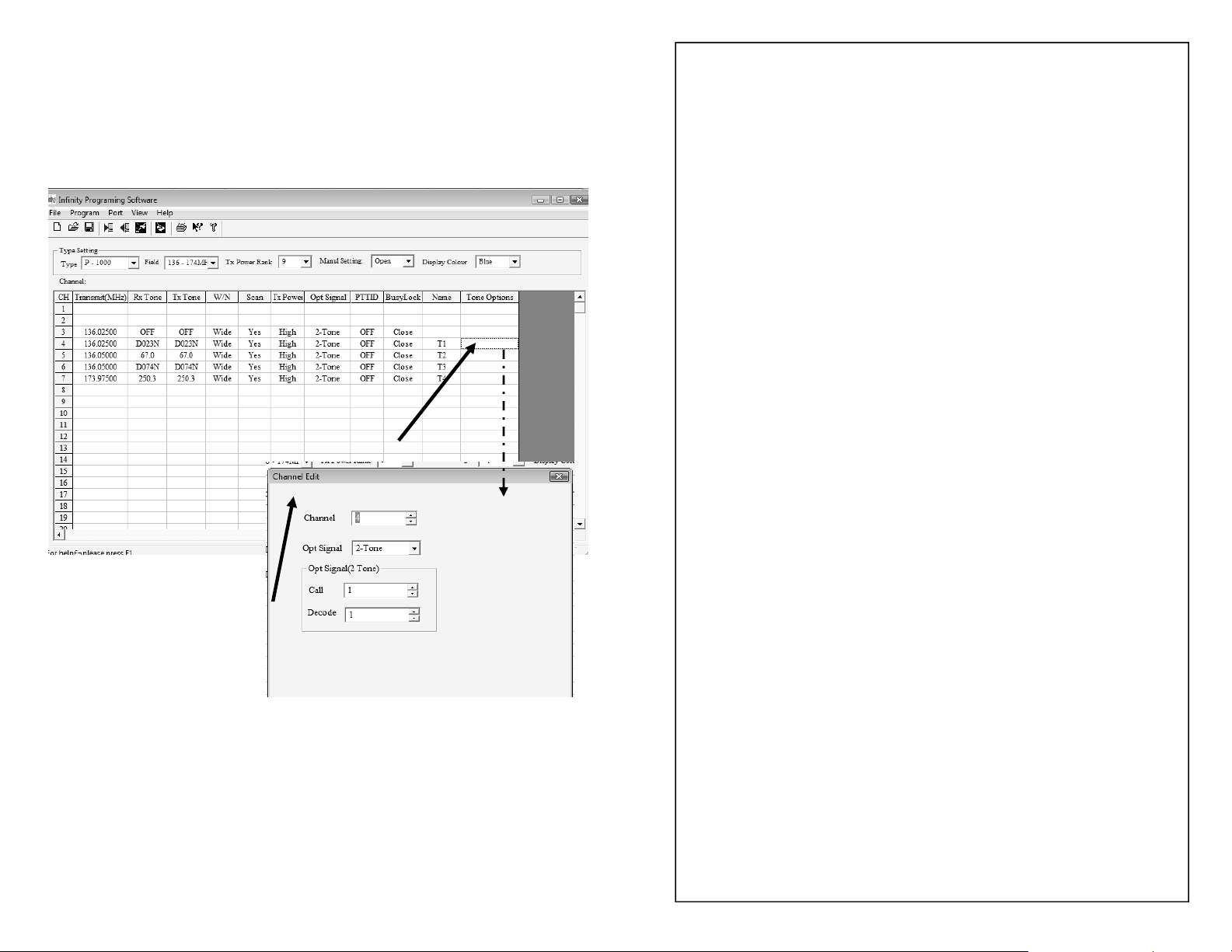
To Generate a Call (Tone) Group Page
(Use by Fire Chief, Command Staff etc.)
First: Your radio must be programmed to send a page
(set to encode)
Double Click on the “Tone Options”
box on the corresponding channel
OPERATIONAL INSTRUCTIONS & SAFETY GUIDELINES
RF ENERGY EXPOSURE IS DETERMINED PRIMARILY BY
THE DISTANCE TO AND THE POWER OF THE TRANSMITTING DEVICE. In general, RF exposure is minimized when the low-
est possible power is used and transmission time is kept to a minimum
consistent with effective communications and the antenna is at the
furthest possible distance from the body. Users should transmit no
more than 50% of the time and follow the guidelines:
To Transmit and Receive: You must be properly licensed by
the FCC or your governing radio communications authority
to use this radio on the programmed frequencies.
To Transmit, first hold down the MON (Monitor) button for a moment
to make sure that the channel is not busy with other traffic that you
may not hear this depending on the TONE that may be programmed in
shared transceivers if the channel is a shared frequency with other
users with different CTCSS/CDS Tones. You may also look at the signal strength meter to ensure that the channel is clear.
To transmit: Push and hold the Push– to-Talk (PTT) Button; speak in a
normal voice. There is a 1/4 second delay before the radio transmits
as the antenna is tuned to the frequency/channel being used
This box then pops up
and should show that
this channel may receive
(Decode) as well as send
out ( Call/Encode) a 2
tone page.
The Tone Frequencies
for both Encode (Call)
and Decode (Receive)
are set up as shown on
page 33.
38
To Receive, release the PTT button.
Hand-held Transceiver Operation:
Hold the radio in a vertical position with the radio approximately 1.5 to
2.5 “ away from your lips.
Body Worn Application:
As in most cases whenever using an approved case and body pack for
this transceiver or not, use of this radio with the antenna touching the
body may exceed the FCC RF exposure guidelines.
Antennas & Batteries
Use only Infinity supplied and approved antennas and batteries.
Use of non approved accessories and attachments as well as
user modifications could not only damage the radio and void
warranty, but also may void FCC regulations as well as
exceed RF exposure limits. DO NOT OVERCHARGE BATTERIES. Consult Infinity or your Authorized Reseller/ Distributor
if you have any doubts or questions.
3
Page 4

About Infinity: Infinity radios are sold only through Infinity or
Infinity authorized regional resellers. The radio is also field
programmable using the keypad (if enabled by the software),
or may be programmed by using a computer loaded with optional Infinity programming software with the appropriate interface cable. The sale and use of these radios is restricted to
licensed users only. User takes the responsibility to comply
with FCC requirements.
About Infinity performance: Users have remarked that the
Infinity radio outperforms most if not all major radio manufacturers in direct radio to radio communications (distance). This
is due to the superior design of the radio and the built in antenna tuner used in the transceiver.
User Precautions
The following will assist you in fulfilling any
warranty obligations.
No User Serviceable Parts inside. Refer repair to Factory Au-
thorized Personnel only.
Using your Paging Radio
Typically your radio will have one paging channel .
When using the radio as a paging receiver, set the
radio to that channel.
Turn the volume control up all the way.
When the radio receives and decodes a valid two
tone signal, the radio will emit an audible chime, as
well as allow you to hear the message being broadcast by dispatch.
It will continue to allow you to hear the radio traffic
until the last transmission occurs or when 20 seconds
time of no carrier has elapsed. After 20 seconds of no
radio traffic on the channel, the radio will revert back
to page receive mode.
Do not use the transceiver or charge the battery in an explo-
sive environment.
Keep the transceiver out of direct sunlight, DO NOT expose
the unit to extreme heat or cold.
Keep the transceiver out of dusty or humid areas. IF IM-
MERSED IN WATER, TAKE OUT OF WATER AND BLOW
AIR ACROSS SPEAKER AND SHAKE ANY WATER THAT
MAY BE TRAPPED IN FRONT OF THE SPEAKER GRILL.
Do Not Transmit without an approved antenna connected to
the transceiver. Install the battery only after the
antenna is connected to the radio.
Observe common sense when attempting to transmit in areas
such as construction sites, mines, hospitals, hazardous environments, etc..
4
37
Page 5
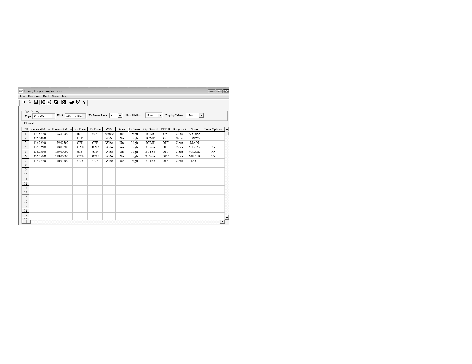
How to use your Paging Radio
Product Features
Once programmed, your radio software programming for the Paging
Receive model should look similar to the screens below. This illustration is a sample scenario of a Chief’s radio.
It is for illustration purposes only depicting typical radio applications of
the P-1000/P1010 P Series radios with paging option.
Examples:
Channel 1 is a repeater channel for Dispatch, no paging receive, on scan
Channel 2 is a weather channel with receive only
Channel 3 is the main repeater channel where one can hear all activity, not on
PRI scan. Hears all radio traffic and page tones. One hears all radio traffic for
Fire, Med, Public Works.
Channel 4 is the Fire Channel with 2 Tone Decode for Fire, using the same repeater as EMS and Public Works. On paging Receive, on PRI scan. Only fire
page calls are heard.
Channel 5 is the EMS channel with 2 tone decode for EMS/MED calls. Uses
same repeater as Fire and Public Works. On paging receive, on PRI scan.
Channel 6 is the Public Works channel with 2 tone decode for Public Works.
On paging receive, not on PRI Scan.
Channel 7 is a DOT channel with 2 tone paging receive, not on PRI scan.
128 channels
5 watt (VHF), 4 watt (UHF) power output
2 Tone Decode and Encode (P-Option)
12.5 KHz narrow/ wi de band spaci ng
wi th 2.5 KHz Channel step
ANI ID code (check compatibility with your radio
system)
VOX operation (for hands free operation)
LCD display with channel, frequency or English
language channel alias
Scrambler (inverted type) operation (to keep con-
versations and information secure)
Three color selectable backlit LCD
Personal Emergency Alarm
Programmable by PC or Front Keypad* [*Keypad
programming access may be locked out by the
software.]
This is the Fire Chief’s radio:
-Fire, EMS and Public Works use the same repeater.
-When on PRI scan, his radio scans and listens for pagesfrom both FIRE
and EMS. (Channels 4 and 5).
-If he is on Channel 3, he hears all traffic, and all tones generated by the
dispatcher ‘s paging terminal.
>IF THE CHIEF’S RADIO WAS PROGRAMMED TO ENCODE, HE
COULD THEN INITIATE A PAGE BY PRESSING AND HOLDING DOWN
THE ORANGE BUTTON ON THE RADIO ON THE APPROPRIATE
CHANNEL UNTIL HIS RADIO BEEPS AT HIM, INDICATING THAT A
PAGE WAS SUCCESFULLYSENT OUT.
36
50 CTCSS ands 104 DCS Normal/Inverted tones,
Selectable
Time-out-timer
Busy channel lock-out
Audible function and channel number (feedback to
user if enabled) in English language through radio’s speaker
5
Page 6
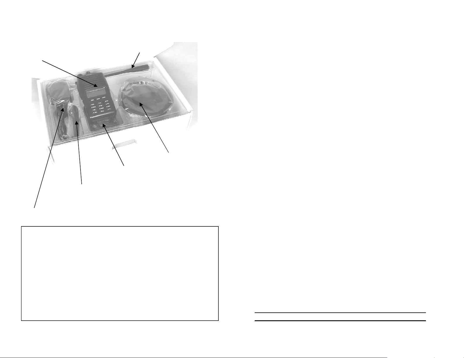
Unpacking (Kit contents)
Step 13:
Once all the required parameters have been entered,
Click on “File”, then “Save As”, and name the file.
Flexible Antenna
Handheld Transceiver
Li-ion Battery
Belt Clip for Mounting
on Battery
Low Voltage DC Adapter for Charger
Charger
Step 14:
With the radio fully charged, NOW TURN THE RADIO ON.
Step 15:
Click on “Program”, “Write to Radio”, and Start.
A time-line progress bar will appear and indicate that the
radio is being uploaded with your data.
IF THIS DOES NOT OCCUR, and an error message ap-
pears, there may be a problem with the Port designation
(selection of Com Port Number) of your computer. To
solve this, click on “Ports”, and change the Port setting,
first from “COM 1” to “Com 2” and then try to write to the
radio again.
Continue this until the program connects to the radio and
writes to the radio.
(You may also read data from the radio).
>>>DO NOT USE THE DEBUG OPTION. This may
cause problems with writing data to the radio.
Unpack carefully the contents of the shipping carton.
Confirm that you have all of the above listed parts in your kit be-
fore discarding the box.
You may also have additional accessories inserted in the box,
such as an extra rechargeable battery, speaker/microphone, ear
mic., PC programming software CD, PC programming cable,
manual, etc. depending on your order.
If any items are missing or have been damaged, file a claim first
with your carrier, then contact your reseller.
6
Step 16:
After the radio has been programmed, (message appears),
you may then turn the radio off and unplug the programming cable. Replace the “SP MIC” plastic cover and you
are set to go.
HINT: If you highlight the tabs with your mouse, a pop
up will appear telling you what each icon is for.
It is assumed that persons programming the radios
are familiar with frequency designations and tones.
35
Page 7

Programming 2 Tone Decode (pager function)
Only available in P Series Radios Continued.
You have 8 sets of 2 decode tones
per paging receive channel that may
Select Decode
Enter your tones A & B per your
communications officer or radio supplier
Enter your timing settings
per your communications
officer or radio/pager
supplier
Transceiver Preparation: IMPORTANT
The factory does not charge the battery before shipping.
Follow these instructions precisely. Failure to insert the battery
as shown will see the pins on the back of the radio pushed in,
causing intermittent contact with the battery. If this occurs, pins
need to be pulled out to make contact with the battery pack.
1) Attach the antenna to the transceiver.
2) With the antenna connected, hinge the battery pack as
shown below into the bottom of the Transceiver, then snap
it in place. Make sure that the battery is properly seated.
HINT: With battery inserted, press down on both
sides of the top of the battery against the radio shell
to snap the battery into
place.
3) You may lock in place the supplied
Battery belt clip at any stage. Depending
on the Model of the battery, the clip may already be assembled onto the battery.
4) Connect the low voltage AC to DC adapter to the Charger
Base. The RED LED will flash and then extinguish.
For all users: This box allows you to set the char-
acteristics of the radio channel: ex: using ANI, 2
tone decode, or having access to a DTMF tone
using keyboard.
34
5) Insert the transceiver into the charger. The RED
LED will light indicating that the battery is charging.
The LED will change color to GREEN once the
battery has reached a useful level. THIS DOES
NOT INDICATE THAT THE BATTERY IS FULLY
CHARGED. Continue to charge the battery
for another 2 hrs. IMPORTANT: Charge the Battery for 1214 Hours before using the radio the first time to condition
the battery. NOTE: The Battery may be charged alone, with-
out the radio connected to it. DO NOT OVERCHARGE.
NOTES:
If the radio is turned on while in the charger, charging times will
increase.
When charging is complete, remove the radio from the charger.
Charge the battery for 12-14 hrs the first time.
When handling the battery or transceiver, do not short the ex-
posed battery connections.
7
Page 8

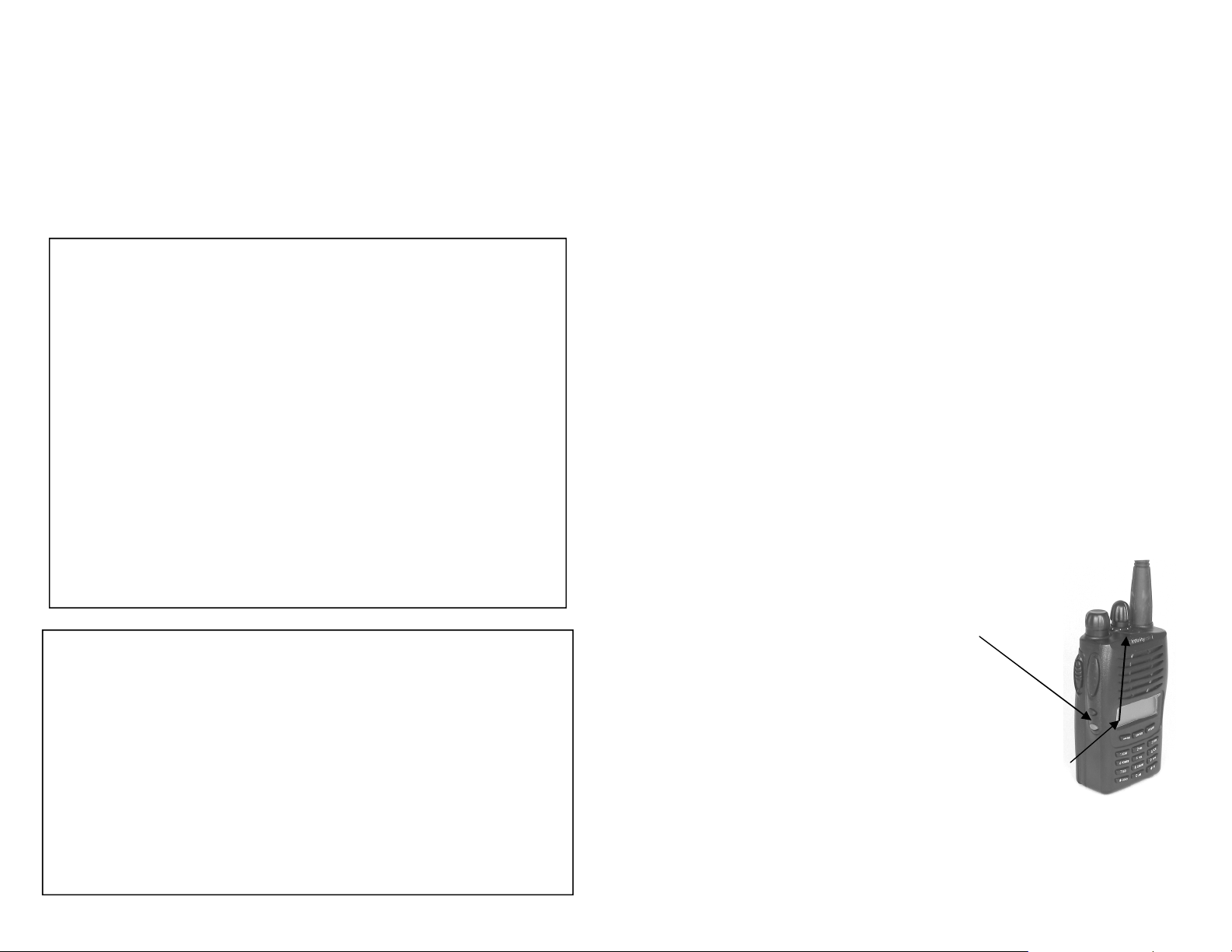
Getting to Know your Radio
Setting the 2 TONE PAGER Receive (Requires P Option radio)
Channel Selector
(Selector also used for scrolling
through programming steps
when in front keypad programming mode)
On/Off
Volume
Control
PTT
MON Key
Call Key
*When MONI & Call
Key pressed and
held down, creates
an audible and
transmitted alarm
signal for the
duration of
the TOT.
FUNCTION
Key
ENTER
Key
TX ON
(Also shows
Programming Data
received
from
PC (when
flashing))
ESCAPE/
VFO
Key
dB Gain
Flex Antenna
Speaker
Mic Element
LCD
LED
Set to DECODE for
receive of 2 tones
First, set the 2 tone frequencies for the first
group. You may have
more than one group as
seen above.
Enter the A and B tones
SEE PAGE 21 FOR TIMING
DETAILS
Set to 2 tone
If you have more
than one group, ac
cess the tables for
the other groups as
needed.
Removable Cover for
Speaker/Mic
Connection.
Battery Lock
(on both sides of
radio)
NOTE: Uses a K style
(Kenwood) connector.
8
In this situation, this radio user is
not allowed to use the orange button to create a 2 tone page call to
other radio users.
If we are to receive Tone Group 1
from the above screen, we need to
associate this with the channel.
In this case Channel 4 is to receive
the tones set up in the Decode
menu for group 1.
33
Page 9

Setting ANI, MONITOR button
Set to PD1200
for MDC1200
(Fleet sync for
Kenwood)
Protective
plastic film on
LCD display.
This should be
removed when
radio is placed
in service
Set ANI ID,
end or
beginning of TX.
32
This sets the
MONI Button
function to
open up squelch
using PF1 button (Page 8)
(default)
Double click on Tone Options, this Box appears.
Make sure that the Channel
selected on the line appears and says PD1200
Li-Ion
Battery
Pack
Keypad
Lock
Key
Inverse
TX/RX
Function
Key
9
Page 10

Radio Controls
Power On/Off
Volume Control
Turns radio On/Off.
Adjusts volume.
Max Power = 9
Do Not Change
TX Power = Hi
Do Not Change
“Open” allows one to
use keypad on radio
to program radio,
“Close” disables this
function
TX Indicator
Busy Indicator
PTT Key
MON (Monitor) Key
CALL Key
NOTE:
In the P VERSION for 2
Tone Decode, this key may
be configured in the s/w to
initiate a Page to all radio
users. In this mode when
this orange button is
pressed and held down until
a “beep is heard” from the
transmitter, it sends out a
page (ENCODE Mode) to all
radios on that channel.
CLR/VFO
10
Indicates radio is transmitting.
Also flashed when in programming
mode and using the programming
software: flashed when data is being exchanged between the radio
and the PC connected to the radio.
“Gas gauge” style bar indicator
shows received signal strength,
and TX power out
Keys the radio’s transmitter
When pressed, opens up the receivers squelch and removes any
CTSS or DCS digital tone
STD: When pressed and held for 2
seconds, sends a sub-audible tone
(1750 Hz) over the air, to be heard by
another Infinity brand radio. This activates an audible chime on the receiving Infinity radio.
Also used to start the “Man Down”
Alarm locally and sends an alarm over
the air for the duration of the TOT
setting heard through the RX and TX
radio’s main speaker when pressed
simultaneously with the MONI key.
OPT in P MODE: Sends out a 2 tone
page if radio set to ENCODE.
Used as “Return” or “Escape” key
when programming, as well as
other functions when in programming mode.
Enter in this screen: RX and TX Frequency, RX/TX Tone (if
used), Wide or Narrow Band Operation, YES or NO to
Favorite Channel Scan Added. ANI typically is off. Busy
lock prohibits transmission when channel is busy.
Set TOT to 60
secs.
Set Squelch
to 3
Set Priority
Channel to
the channel
number that
you want to
home the
radio to
Enter 6 character
Alpha-Numeric
channel alias
Other Options Menu:
Set Language to ENGLISH
For ANI
see page 25
Above diagram represents typical
programming for most users
31
Page 11

Step 9:
Double click on the “Infinity” icon on
the desktop to run the s/w
Infinity.lnk
Step 10:
Once the software is up and running, on the main screen and
under the “Type Setting”, select the radio model number in the
drag down option.
Step 11:
In the “Field” box, drag down and select the frequency range of
your radio. Ex.:136-174 MHz if VHF, etc. depending on model.
Step 12:
Enter all your frequency information and other data; (including
RX and TX Tones, wide or narrow band, enter YES or NO for
SCAN (this applies only to Priority Channels only accessed on
the keypad by the User when one selects PRI function (>do not
enter Yes on all channels: “All Channel Scan is automatically
selected by the user pressing “MENU and Scan” on the keypad)
Typically enter Yes on 3-5 channels to avoid missing key radio
activity.
LCD Screen
30
12.1 Favorite Channel Scan (activated
when MENU and PRI pushed on keypad)
11.2 Frequency
Range
11.1 Radio Model Number
DTMF Option used for stan-
dard radio operation allow-
ing use of keyboard as
DTMF touchtone.
2 TONE
P VERSION
ONLY
Access to Front Keypad
Programming:
OPEN: YES
CLOSE: NO
Default=OPEN, YES
11
Page 12

About Radio Operations. Terminology.
In a wireless Land Mobile Radio (LMR) Communications system,
there are two modes of operation: DIRECT (communicating on
the same transmit and receive frequency between radio users,
sometimes called Radio to Radio); and over a REPEATER (where
a portable or mobile radio transmits on one frequency and receives on another).
In DIRECT MODE, there may be obstacles such as buildings or
uneven terrain affecting the transmission over long distances of
communications between two or more low power (ex. 5 watt) portable radios. In a REPEATER configuration, a radio receiver and
high power radio transmitter (example 50 to 150 watts) with two
antennas is located on a mountain top or elevated location.
Repeater Operation
Step 5:
Once the installed application is running and you reach
the “Customer Information” window, you may enter the
serial number of the radio into the serial number field (or
the word “infinity”. (The serial number for the radio is located on the back of the radio where the battery normally
sits.) We suggest entering Infinity as the entry. You may
enter “infinity” at all prompts, the s/w is not dependent on
passwords or serial numbers.
Step 6:
Once you have gone through successfully the Install Setup
Notice, an Infinity icon will be automatically placed on your
computer’s desktop. The icon will look like the one below,
labeled “Infinity”.
Portable Unit 1
Receive: 154.875 MHz
Transmit: 156.090 MHz
Repeater
Receive: 156.090 MHz
Transmit: 154.875 MHz
When it Receives a signal the repeater transmitswhat
it receives simultaneously on the other frequency.
When using a handheld radio, the Repeater due to its better and
elevated location receives much better the low power signal of the
hand held or other radio units. Once received, the transmitter retransmits simultaneously the received radio transmission from
the handheld or mobile radio on a frequency that differs from the
received signal. This so-called frequency offset is necessary to
prevent the strong transmitted signal from disabling the Repeater's receiver. When strategically located on top of a high
building or a mountain top, the Repeater can greatly enhance the
performance of a wireless network by allowing communications
over distances much greater than would be possible without it. In
this case coupled with higher power, the Repeater “repeats” the
communications from the hand held or mobile unit that it receives,
and increases the range due to the higher power and better antenna and location of this relay station .
12
Portable Unit 2
Receive: 154.875 MHz
Transmit: 156.090 MHz
Step 7:
Locate the programming software cable that was included
with your radio. Plug the RS-232 COM connector of the
cable (DB9 connector) or the USB connector into one of
your available COM or USB ports on your computer. If
using a serial cable, remember which COM port it was inserted into….as you will need to know this designation
later. Example COM1, COM2, COM3, or COM4.
Note: If using the PG-2 USB Cable and Software, follow the specific software HELP GUIDE that accompanies your USB Software Kit. YOU MUST INSTALL A
USB DRIVER TO YOUR PC OR LAPTOP> Follow the
USB installation instructions closely. Ensure that device manager sees these ports as such, COM1, COM2
etc…for USB operation.
Step 8:To program:
Insert the other end of the programming software cable
plug into the speaker/microphone jack of the radio. To do
so you will need to pull back the upper portion of the plastic cover located on the right hand side of the radio labeled
“SP MIC”, and plug in the connector firmly. KEEP RADIO
POWER OFF AT THIS STAGE.
Note: Do not confuse the “SP MIC” plastic cover
Infinity.lnk
with the PTT key.
29
Page 13

2. Using Software to Program the Radio:
To program your radio with software, you will need to order
the Model PG-1(serial DB-9 connector to Radio) or PG-2
(USB to Radio) models.
Minimum Computer System Requirements for Software:
Operating System: Win 2000, XP
Ram: 128MB min
Processor: 850 MHz min
About CTCSS and DCS Tones
Continuous Tone-Coded Squelch System or analog CTCSS
is a circuit found in a two way radio transceiver that is used to
reduce the annoyance of listening to other users on a shared two
way radio system, where more than one user group is on the
same channel and frequency, (called co-channel users). CTCSS
filters out other users if they are using a different CTCSS tone or
no CTCSS. DCS is called Digital Coded Squelch, similar to
CTCSS.
Quick Step Guide
Step 1: Insert the “P1000 Infinity Software” CD into the CD
drive bay of your computer.
Step 2:
Once the CD drive folder appears, double click on the
folder icon.
Infinity Aug 06 SW.zip
Note: In cases where the file was emailed, the file
may be “zipped”. Otherwise clicking on the icon
extracts the program automatically creating an
Infinity Icon on your desktop. It may be either a
RAR or ZIP file. In this instance if you do not have
a program that can open zipped files, you can go
to www.winzip.com or www.rarlabs.com depend-
ing on the type of zip file. Once this is done then
proceed with the instructions.
Step 3:
Extract the contents of the folder in the recommended
directory, or specific directory that you can access
easily when using the unzipping program.
Step 4:
Open up the directory/folder that was just created and
double click on the executable file inside to run it.
Example: One may have both the Fire Dept. and EMS on the
same frequency. During standard operations, one may not want
to hear the other. The two-way radio receiver's audio turns on
only in the presence of the correct sub audible tone that only the
radio hears that corresponds to the respective agency’s programmed sub-tone. Therefore in this application, Fire uses one
sub- tone, EMS another. Conventional radios without CTCSS (or
CTCSS turned off, or seeing the User pressing the MONI button
on the P-1000) would hear all transmissions from both groups.
The Firefighters would have to listen to the radio traffic from EMS
while EMS would hear all conversations from Fire.
If the radios are programmed with 2 different CTCSS tones on
two different channels using the same frequency, units from
each group would only hear radios from their own Department
that are programmed to the same CTCSS or DCS code number
of their group. Using this also reduces missed messages and the
distraction of unnecessary radio traffic from the other Agency.
There are many other uses for CTCSS/DCS often called PL
TONES (Motorola term) or Channel Guard. (A GE term).
Prior to programming a radio one therefore needs to mark down
the following:
-Receive Frequency
-Receive Tone (If CSQ is written, there is no tone used)
-Transmit Frequency
-Transmit Tone
-Whether the radio is to operate in narrow or wide band
-The 6 character description of the radio channel
28
This file will be labeled as “Infinity.exe”.
This information should be available from your communications
officer.
13
Page 14

Basic Transceiver Operation-Quick Guide
To turn the Transceiver On: With the antenna connected and bat-
tery inserted, rotate the power/volume control knob clockwise. All icons
on the LCD shall appear momentarily. The screen after self test will
then revert to the selected default state: with Channel number and with
English Channel Alias name.
Volume and Squelch: The transceiver has a preset squelch level,
which may be adjusted (in squelch set up/programming mode in the
software or by pressing the MENU key and then selecting squelch
when operating the radio in the field.). Lowering this setting opens up
the squelch allowing one to hear more distant or noisy stations. This
should be set to “3” for normal operation.
Adjust volume as needed using the volume control to your requirement.
If there is no one on frequency and nothing is heard from the unit’s
speaker, you may adjust volume by pressing the MON button (opening
up the squelch), and then adjusting the volume level as needed.
Transmitting: It is common practice to hold down the MON button
momentarily to open up the squelch or defeat the CTSS tone that may
have been programmed to avoid transmitting while another station using another CTCSS or DCS tone is on your radio frequency but not on
your tone. If this is the case, you may also consult the “receive signal
bar meter” that also shows relative receive signal strength. If another
station is on frequency you will see the received signal on this bar
graph. If the MONI button would be pushed you would then hear the
other station. Consult your communications officer for use of the this
formality and see if it applies to your agency. Transmit only when the
channel is clear.
Call Tone: Similar to PRS/FRS GPRSM personal family radios, you
may ahead of your transmission alert someone audibly of an incoming
call. This only works with another P-1000/P-1010 series radio. Press
the Orange Call Key and hold it down for 2 seconds. You will see the
Red TX LED light up and the TX signal strength meter on the radio’s
LCD light up, indicating that the radio is transmitting. A “chime” will
heard on another Infinity radio tuned into the same channel.
14
Additional Notes Regarding the Programming of the
P-1000 Series Radio
>Entry of Channel Descriptions using Keypad:
You may use either the front keypad to program the radio, or use
the Infinity Model PG-1 (serial) or PG-2 (USB) programming cable
inserted in the microphone jack which is connected in turn to a
PC or laptop using the Infinity programming software. The s/w
can lockout the user from accessing the field keypad programmability feature of the radio. CONSULT YOUR AGENCY.
If using the keypad: you may program the English Language channel names (up to 6 alpha or numeric characters). To program
manually this channel aliasing using the keypad:
A. Set radio to channel mode (standard operation)
B. With power off, press both “MON” and “MENU” keys, holding the
keys down while radio is turned ON.
C. Keep these keys down until you see the word “SELF” appear on the
LCD. (This denotes that you are in programming mode)
D. Press “ENTER”
E. “CH—001” appears on the LCD.
F. Rotate the channel selector until you reach the desired Channel
number. Press “ENTER”
G. Press “ENTER” repeatedly until you see a series of “_ _ _ _ _
_” (dashes) appear on the LCD, with a small number “10” to the
right. This is the line where you can enter a simple channel descrip-
tion. The first “_” line is flashing.
H. Rotate the channel selector until the desired letter or number ap-
pears.
I. Press the “#” key to advance to the second character position.
J. Repeat the process using the channel selector to scroll through the
numbers and letters.
K. When finished press “ENTER”. Then Press the VFO/MR key twice
to exit the program.
NOTE: With the radio turned on and if the Channel Name
does not appear on the LCD screen after programming the
channel alias, make sure that the NAME option is turned on.
Press the “MENU” button, rotate channel selector to NAME,
rotate the channel selector to highlight “ON”, press ENTER
twice, exit pressing the VFO key. (Page 18, line 15)
27
Page 15

Taking Care of your handheld Transceiver
Your transceiver has been designed using the latest in
technology along with high temperature flame retardant
plastics. Normal regular care an attention will increase the
longevity of certain components.
Handle your radio
with care.
Do not carry the
transceiver by either
the antenna or the
optional external
speaker microphone.
When the speaker
microphone or other
accessory is not in
use, keep the speaker
microphone accessory
jacks covered by using
the rubber flap that is
attached to the radio.
To clean, use a
moistened rag with a
mild detergent, and
with a nearly dried
cloth, clean the case, control knobs, and keypad. Never
use any chemical to clean the unit.
Regularly, wipe the battery contacts with a lint-free
cloth to remove dirt, grease, or any other materials that
may prevent a good electrical connection.
Never Expose the Radio to direct sunlight, heat or cold
for extended periods of time.
Flank Keys
The portable transceiver has the capability to allow the user
to create alarms as well as to easily make changes on the
go.
LOCAL MAN DOWN AUDIBLE ALARM
Turn radio on.
Press both the MON and Orange CALL push buttons
simultaneously. A local oscillating tone will be heard
through the transceiver’s speaker and send a signal for
the duration of the TOT time on the channel that the radio was set to, sending out an audible signal over the
air. For local speaker, adjust volume as needed.
KEYPAD LOCK
To lock access to the front keypad keys so that they may
not be activated or pressed in error with the radio perhaps
sitting in the back pocket etc.,
Press and hold down the *LOCK button 2-3 seconds.
To UNLOCK, press and hold down the *LOCK button
again for 2-3 seconds.
REVERSE (INVERTED) FREQUENCY OPERATION
For ground operations and to invert the TX frequency split
with the RX frequency, press and hold down on # T-R key
for two seconds until “R” appears on the LCD display. To
cancel, press the same button once again for two seconds.
SCANNING: ALL Channels: In Channel Mode: Press the
MENU button, either rotate the channel selector until you
see SCAN ? displayed on the LCD display. (or press
Menu then the number 1 (SCAN) key). Press the ENTER
button on the keypad. The unit will start its scan going
through all channels. To stop, press the ENTER BUTTON.
When activity is detected, the radio will suspend the scan
for 5 seconds unless the PTT or ENTER key is pressed to
end the scan and lock on the active channel.
See next page regarding information on scanning PRIORITY channels.
26
15
Page 16

Flank Keys, con’t
PRIORITY (PRI) CHANNEL SCAN: By assigning certain
channels during radio programming (using the keypad or s/w)
to be considered as PRIORITY channels, press MENU, press
the PRI key, press ENTER. The radio will scan the priority
channels. (If using s/w to program these PRIORITY channels, mark YES under the SCAN heading; using the keypad
for programming, select ADD on line 7.
Common Radio Concepts
Understanding Squelch: The radio typically with a clear chan-
nel is silenced. Upon reception of a carrier from another transceiver or repeater, and with CTCSS/DCS programmed to accept
a programmed and valid tone, only then does the receiver hear
the transmission. In rare occasions if the squelch level is set too
high, weak signals may not be received properly. To do so you
may press the MON button to open up the squelch or “loosen” the
squelch.
SELECTING SCAN PARAMETERS: This allows one to
change the type of scan. Press MENU, use the channel selector and scroll until you see SCANS? 13 on the LCD Display, press ENTER, rotate the channel selector until the desired type is seen, press ENTER.
*Default is set to “T0”.
T0
CO
SE
Time Operated Scan: After stopping on a
channel for a preset time, the radio will continue to scan unless locked in by the User.
Carrier-Operated Scan: Radio will lock onto a
busy channel and start its scan once there is
no activity on the channel.
Search-Scan: Will lock and stay on the channel until the channel selector switch is moved
To Transmit DTMF (touch-tone) Codes: Press PTT and
press the number keys as required on the front keypad. TO
NOTE: Alpha keys are entered as follows:
MENU: A VFO/MR: C
ENTER: B Orange CALL BUTTON : D
SELECTING MODES: Frequency or Channel
With Power turned off, hold down the ENTER button and
turn the radio ON. The radio will then show FREQUENCY.
To revert to Channel Mode: Turn radio off, then hold down
the ENTER key while applying power to the radio. When in
Frequency mode you may increases, decrease frequency by
turning the channel selector. In Freq Mode: Press the VFO/
MR key to show simultaneously both Channel and Frequency.
16
Receive CTCSS/DCS functions that have been programmed by
your dealer or your communications specialist will allow you to
hear radio traffic only when the these sub-audible signaling tones
have been heard from another similarly programmed radio by
your receiver. Only then will the radio allow you to receive a transmission of the same tone. If tone decoding is not used or programmed in the transceiver, then all conversations on the programmed frequency will be heard.
ANI Radio ID is a feature that transmits a unique ID number
that has been programmed into your radio. Using the s/w, in the
Radio ID field, program all radios with 123 as a radio ID number
to be sent at the beginning of the transmission. This allows all radios in this group to see each other. Then program each individual
radio with an ANI Code (number that corresponds to the radio call
of the user), with end of transmission selected. Each radio has a
unique number. Using this feature may or may not affect the receipt of some repeater based ID transmissions and may not work
with all Motorola MDC1200 systems. Test first to evaluate the
situation.
Reverse TX/RX When this function is enabled by the user in
situations where the user does not want to trip the repeater but
have local ground operation conversations to local responders
and not heard over the repeater network, this may be accomplished by pressing and holding down the “# T-R” key until the “R”
appears on the LCD. Radio units that are in close proximity to
your area of operations will hear you on the repeaters output frequency. They also, as well as you, will hear the repeater. The
corresponding CTCSS/DCS tones will also follow automatically.
DTMF Tones: While pressing the PTT button, and by pressing
any of the 10 numeric keys, a corresponding DTMF tone will be
25
Page 17

Other:
Audible Voice Feedback: The radio may announce in
plain English audibly through the unit’s speaker the various functions and channel numbers of the radio to the
User. To enable this unique feature: Press MENU, then
rotate the channel selector until VOICE? 14 is displayed
on the LCD. Press ENTER, rotate the channel selector
until ON is seen, press ENTER. A voice will say “Enter
On” through the unit’s speaker. Press ENTER , then
press the VFO/MR key TWICE to exit. Turning the channel selector or pressing any key will provide the user with
audible feedback of the function accessed by the user.
Backlight Color Selection: Allows you to change the
color of the backlight: Press MENU, rotate the Channel
Selector switch until LED? 07 is seen on the display.
Press ENTER, then rotate the channel selector until the
desired background color is seen. Press ENTER, Press
the VFO/MR button twice to next (escape).
To select the type of LCD Backlighting (depending
on the selection, this may decrease battery capacity):
Press MENU, rotate the Channel Selector switch until
LED? 06 is displayed. Select then from:
AUTO: Display is lit for aprox. 7 seconds when a
key is pressed or channel selected.
ON: Display is always lit when radio is turned On.
OFF: Never lights.
Once selection is made, press ENTER, then press VFO/
MR to exit.
Note: depending on model, specifications may vary.
Specifications subject to change without notice.
Consult the web site for latest information
24
Other Selections: VOX POWER (high, low)
Squelch Scrambler
Beep ANI (ID)
Scans Voice
CTCSS DIFFR (freq shift)
TOT (Tx Time-out)
All may be selected using the MENU key and rotating the channel selector to the desired function, pressing ENTER once the
selection is made, then pressing the VFO/MR button to escape.
17
Page 18

USER MENUS FOR RADIO OPERATION
Note: Regarding the selection of the CTCSS, DCS or NO TX/
RX tone (s), in Tone Menu (line 3), previous page, by pressing the “* LOCK” key toggles you between the options:
No Tone, CTCSS Tones, DCS Digital Tones, No Tones, etc.
Once you have selected the desired function feature, (No Tone, CTCSS
analog Tone, DCS Digital Tone), Press ENTER, and then Rotate the
Channel Selector until to see the appropriate Tone for that Channel,
then press ENTER to select.
Your radio has 50 CTCSS analog Tones and 104+1 Digital DCS
Tones that are pre-loaded in the radio’s CT Tone library.
18
Found below is for your convenience is a conversion table
from CTCSS tones to Motorola Tone Designators.
CTCSS Motorola CTCSS Motorola CTCSS Motorola
67.0 XZ 71.9 XA
74.4 WA
77.0 XB 79.7 WB 82.5 YZ
85.4 YA 88.5 YB 91.5 ZZ
94.8 ZA 97.4 ZB 100.0 1Z
103.5 1A 107.2 1B 110.9 2Z
114.8 2A 118.8 2B 123.0 3Z
127.3 3A 131.8 3B 136.5 4Z
141.3 4A 146.2 4B 151.4 5Z
156.7 5A 162.2 5B 167.9 6Z
173.8 6A
NO TONE
CSQ
23
Page 19

USING THE FRONT KEYPAD TO PROGRAM THE RADIO
(For 2 tone decode, programming done using software only)
The tree below guides you through the various line items that you
may program per radio channel. Pressing the ENTER key allows
you to jump from one line item to another.
TO ENTER PROGRAMMINGMODE (Refer to Page 20): 1) Press MONI + MENU keys
and HOLD DOWN; 2) TURN RADIO ON WHILE HOLDING DOWN THESE TWO KEYS
UNTIL “SELF” APPEARS ON LCD, (aprox 2 secs); 3) THEN PRESS ENTER AND
FOLLOW THE GUIDE BELOW
Channel
Selector
Channel
Selector
Channel
Selector
Channel
Selector
Channel
Selector
Channel
Selector
Channel
Selector
Channel
Selector
Channel
Selector
22
Troubleshooting Notes:
1) If your radio “transmits by itself”, make sure that the VOX (voice
activated switch) is turned off.
2) If you cannot hear a station using a repeater calling you, yet you
may “hit” and trip the repeater, try turning off the ANI function as
it may not be compatible with your repeater.
3) If you cannot be heard, and you cannot trigger the repeater, and
yet you see the power bar for transmit power activate when you
are transmitting as well as when another radio has triggered the
repeater, this would indicate that the CTCSS or the DCS digital
tones are reversed.
4) You can hear a radio next to you, but cannot be heard, make
sure that you have not entered in reverse transmit and receive
frequencies.
5) You can hear the repeater but may not access it after checking
the above points, if you are using a 2.5 channel step, make sure
that the radio has been programmed to accept the 2.5 channel
step. To do this, enter the “Frequency mode” of operation, (see
page 16). This operation selection is confirmed by seeing the
frequency being displayed on the LCD. Then, by pressing menu
and accessing the “Step” menu (line 20) and programming in
the step ( seeing STEP025 appear on the LCD), you have now
selected the radio to the 2.5 KHz channel step. Press Enter to
save. Then Exit by pressing the VFO/MR key twice. Then return
to “Channel Mode Operation.” (see page 16 on how to return to
Channel Mode).
6) IF USING S/W TO PROGRAM THE RADIO:
At times several models of PC or laptops have added an extra byte,
turning the VOX (Hands-free) Voice Operated Switch for transmit to
the “ON” position. Before distributing a radio, make sure that the
VOX indicator on the LCD is turned off (does not appear).
7) The LCD display on the radio turns itself on or off by itself. This
may indicate that the battery is not making contact with the 3 copper
pins on the back side of the radio. This may happen if the battery
was not inserted properly, by "hinging" the battery in place, bottom
first into the radio, as shown on Page 7. To correct an intermittent
connection, use your finger and gently pry back the three copper
pins on the back of the radio towards you and downwards towards
the base of the radio. Then insert the battery into the radio. With the
radio turned on and as a test, squeezing the radio between your
fingers (front and back of radio) should not see the LCD display or
radio turn off.
19
Page 20

Entering the Radio Programming
Before Programming your radio:
Mode using the Front Keypad
Step 1: With the radio turned off,
locate the MONI and MENU
keys. Position your fingers
as shown.
Find a comfortable position.
Step 2: Then, while holding
down the MONI and MENU,
Keys,
Turn the Radio ON,
keeping these 2 keys held
down until you see the word
“SELF” appear on the LCD
Screen.
Step 3: When “SELF” appears on
the screen, this lets you
know you are entering the
Radio’s Programming Mode.
Press “ENTER”
“Channel 01” appears
on the LCD display. This
indicates to you that you are ready
to program Channel 01. If you wish to
Program Channel 01, press “ENTER”.
NOTE: If you wish to program another Channel
other than Channel 1, rotate the Channel selector until you
see the desired Channel number, then Press ENTER.
When you have completed programming all your channels, press the VFO/MR key twice to exit.
>>Follow the Programming Tree as found on Page 22.
20
MONI
MENU
Ensure that before programming your radio either using the
front keypad or software that you first write down on a
paper the following information that will be needed, this prior
to programming:
1) Receive Frequency
2) Receive PL tone (CTCSS, DCS, or none. NOTE: CSQ on a list
denotes that no PL or channel guard tone is used.)
3) Transmit Frequency
4) Transmit PL tone
5) If the frequency used is narrow or wide banded.
For 2 Tone Paging Radio Operation,
either for Decoding (receive) or Encoding (creating a 2
tone transmission), you will need to use the
Optional Paging Radio Software, as these functions are
not keypad field programmable.
You will need also to find out and make note of the “A”
and “B” Tones for your paging system, and their spacing
as it applies to your radio system for successful 2 tone decode (or encode) operation.
HINT: For use with commonly used MOTOROLA Minitor pag-
ing systems, the following settings should be used:
-First delay: 0.5 (length of first tone)
-Second Delay: 0.5 (length of second tone)
-Interval Time: 2.0 (time between tones A & B)
-Long Delay: 5.0 (when creating a page, (Encode mode only),
this is the time that radio waits once PTT is pushed to send out
series of A&B tones)
Consult your communications officer or paging
communications supplier to ensure that these are the cor-
rect timing sequences for your Agency
or Department.
21
 Loading...