

Page 1
subwoofer instructions
Thank you for purchasing an Infinity Kappa Perfect VQ
subwoofer. Kappa Perfect VQ subwoofers are engineered to
provide unparalleled audio reproduction at even the highest
output levels, and are constructed using state-of-the-art materials
for unequalled performance and longevity. To ensure the best
subwoofer performance possible, we recommend that a qualified
professional perform the installation. Although these instructions
provide enclosure specifications and explain how to install a
Kappa Perfect VQ subwoofer in a general sense, they do not show
specific box-construction details or vehicle-specific installation
methods. If you don’t feel you have the knowledge, experience
or necessary skills to install the subwoofer yourself, ask your
authorized Infinity dealer about professional installation options.
Remember to keep your sales receipt and this manual in a safe
place so they’re available for future reference.
Page 2
INTRODUCTION
Kappa Perfect VQ Series subwoofers
are unique because they provide
variable Q. Q adjustments may
allow the subwoofer to be optimized
for a particular enclosure or application and may provide the user with
optimum performance for several
applications in a single enclosure.
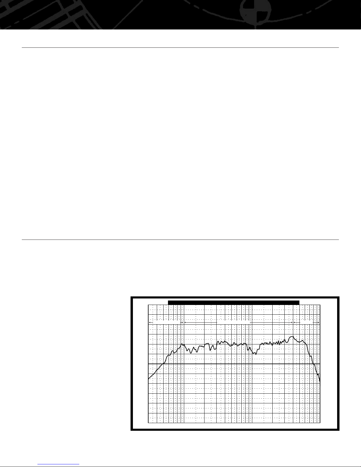
The frequency response of every
speaker includes three distinct regions
characterized by flat amplitude (passband), high-frequency attenuation
(stopband-high) or low-frequency
attenuation (stopband-low) (see
Figure 1). Midrange speakers and, to
a lesser extent, tweeters are used to
reproduce frequencies in the region
where they exhibit flat frequency
response. Subwoofers, on the other
hand, are used in a region of lowfrequency attenuation, but those low
frequencies are what we want the
subwoofer to reproduce. Subwoofer
system design is almost entirely
an effort to extend the region of
flat response to the lowest possible
frequency or to shape the frequency
response in the band of reproduced
frequencies. Qes and, consequently,
Qts are the parameters that best
describe the behavior of a subwoofer
in the range of frequencies it is most
often used to reproduce.
2
A FEW WORDS ABOUT
POWER HANDLING
The power-handling capability of any
woofer is related both to its ability to
dissipate heat and to the maximum
excursion limits of its suspension.
Once the speaker’s voice coil moves
outside the magnetic gap, power
can no longer be converted into
motion and all the amplifier’s power
is converted into heat in the voice coil.
Voice-coil heating is the greatest
detriment to speaker longevity, so
overexcursion should be avoided.
Since excursion characteristics are
very different for each type of
enclosure, power handling will be
different for each enclosure type.
Sealed enclosures exert the most
control over the motion of the subwoofer at the very lowest frequencies
because the air inside the box acts
as a spring, opposing the motion
of the woofer’s cone. Larger boxes
allow more excursion, providing more
low-frequency output than the same
woofer in a smaller box, for any input
power level. When placed in a sealed
box much larger than the equivalent
compliance (Vas) of the subwoofer,
it will perform as if it were in an
infinite-baffle application, with the
attendant lower excursion-limited
power handling.
Vented and bandpass enclosures allow
the least excursion for the amount
of sound output (near and above the
resonance frequency of the enclosure).
The mass of air contained in the
port provides an acoustic load to the
woofer’s cone at the tuning frequency,
and this added mass decreases
excursion so that the subwoofer’s
motor is, essentially, coupled to the
air in the port. Vented boxes do not
provide adequate control below the
frequency at which the box is tuned,
so proper design and a subsonic filter
are important. A vented bandpass box
will allow the least cone excursion,
provided a subsonic filter is used.
Infinite-baffle, or “free air,” mounting
allows for greater excursion than does
mounting subwoofers in enclosures.
The power handling of a subwoofer
mounted in an infinite baffle will be
reduced by nearly half its rated-powerhandling spec.
Voice-coil overheating and burning
have only one cause – exposure to too
much power for too long. An amplifier
driven into severe clipping or squarewave can output much more average
power than the average power of a
clean sine wave of the same level.
Audible distortion in the sound is a
clear indication of amplifier clipping
and should serve as an indication that
your speakers may be in danger of
being damaged.
VARIABLE Q (PATENT PENDING)
30 10050
Hz
200 1K500 2K 5K 10K
SPL vs Frequency
dBSPL
Deg
180
150
120
90
60
30
0
–60
–30
–90
–120
–150
–180
–10
–15
–20
–25
–30
–35
–40
–50
–45
–55
–60
–65
–70
LOW-FREQUENCY
ATTENUATION
HIGH-
FREQUENCY
ATTENUATION
FLAT AMPLITUDE
Figure 1. Frequency response of a speaker.
Page 3
3
The operation of a subwoofer (or any
moving-coil loudspeaker) is divided
into two regions. Below resonance,
where the motion of the cone is
“stiffness-controlled,” the subwoofer’s
suspension does a great deal of the
work of opposing the inertia of the
moving assembly – the stiffness of
the suspension controls the motion
of the cone. Above resonance, where
the motion of the cone is “masscontrolled,” the subwoofer’s
suspension has little effect on the
motion of the cone, and the motor
must do all the work of opposing the
inertia of the moving assembly – the
motor controls the motion of the cone.
“Opposing inertia” simply means
starting and stopping the motion of
the cone.
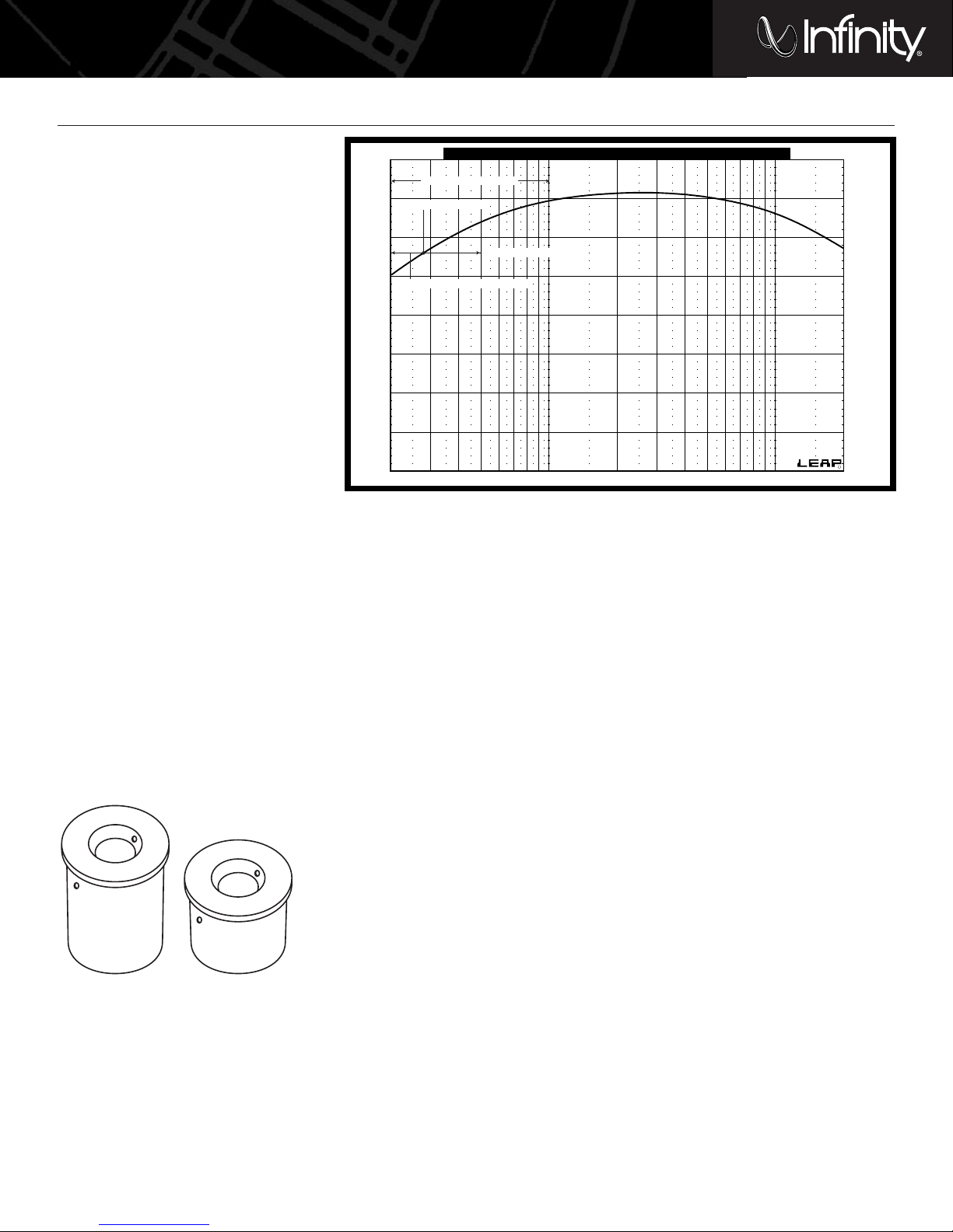
The metal inserts included with your
Kappa Perfect VQ Series woofer are
used to adjust the amount of force the
motor can exert on the inertia of the
moving assembly. The largest of the
two inserts (LowQ), when installed in
the woofer’s polepiece, will provide
the highest motor force and, consequently, the lowest Q (see Figure 3).
The smaller of the two inserts (MidQ)
will provide less motor force and
somewhat higher Q and the woofer
used without an insert will have a
much higher Q. (continued)
VARIABLE Q
Figure 3.
20 50Frequency 100 Hz 200 500 1K 2K
Subwoofer Operating Range
dB
95
90
85
80
75
70
65
60
55
OPERATING RANGE
MASS-CONTROLLED
RESONANCE (Fs)
STIFFNESS-CONTROLLED
Figure 2. Subwoofer operating range.
Page 4
4
Kappa Perfect VQ woofers are designed
to provide optimum system Q and
frequency response in infinite-baffle
applications or in very large enclosures
with no insert installed in the polepiece.
The smaller of the two inserts is
intended to be used with woofers
mounted in medium-sized sealed boxes
and vented boxes. The largest insert is
intended to provide optimum Q for very
small sealed or vented boxes or for use
with woofers used in SPL competition,
where the enclosure is designed to
provide the highest output possible
at a single frequency.
While it may seem that the most
forceful motor will provide the best
performance in all applications, in
reality that is not the case. When a
woofer is mounted in an enclosure, the
resonance of the woofer becomes the
resonance of the combination of the air
inside the box and the woofer, and Qts
(speaker Q) becomes Qtc (system Q).
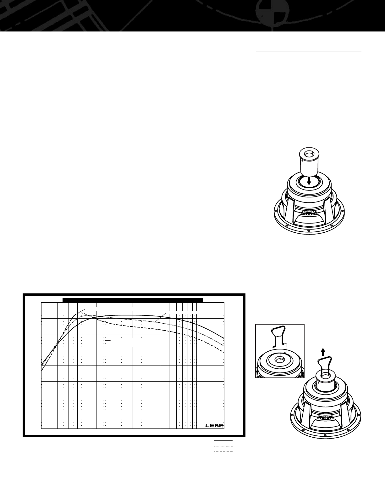
For example, Figure 4 shows the
response of a Kappa Perfect VQ
subwoofer in a sealed box optimized for
use with the MidQ insert. Pictured on
the graph are the responses of the
woofer and enclosure combination with
the LowQ insert installed; with the MidQ
insert installed; and without an insert
installed (HighQ). The difference in the
performance of the woofer with its
various adjustments is increased output
at and slightly above system resonance
(Fc) with increasing Q, but reduced
output at the lowest reproduced
frequencies. The reduced motor force
supplied by the lower-Q designs results
in reduced sensitivity (SPL 2.83V/1m),
but the effects of that reduced
sensitivity are greatest above 100Hz.
Subwoofers in cars are typically used
for frequencies below 100Hz, so the
reduced sensitivity is inconsequential.
The difference in behavior for vented
and bandpass enclosures is similar, but
the enclosure design is more complex
and should be given special attention.
Although Kappa Perfect VQ subwoofers
were designed with specific uses for the
inserts in mind, there are many different
enclosure and insert combinations
that may suit your taste. The intended
combinations are highlighted as
“optimum” on the charts in the section
titled “Choosing an Application and
Enclosure”; several other applications
are also included.
VARIABLE Q (CONTINUED)
20 50Frequency 100 Hz 200 500 1K 2K
Effects of Variable Q
dB
95
90
85
80
75
70
65
60
55
SYSTEM RESONANCE (Fc)
lowQ
midQ
highQ
REDUCED SENSITIVITY
TYPICAL LOW-PASS-
CROSSOVER FREQUENCY
Figure 4. Effects of Variable Q.
Your Kappa Perfect VQ subwoofer is
shipped from the factory without an
insert installed. After determining
which application and enclosure is
most suitable for your system, install
the appropriate insert in the woofer’s
polepiece by aligning the insert with
the hole in the woofer’s polepiece and
simply dropping the insert into place
(see Figure 5).
Figure 5. Installing the insert.
To remove the insert, squeeze the
insert tool to compress the area
between the two tabs, insert the end
of the tool into the vent in the center
of the insert and align the two tabs
with the two small holes inside the
vent. The tabs should lock into the two
holes. Pull firmly on the tool to
remove the insert (See Figure 6).
Figure 6. Removing the insert.
Note: Magnetic force holds the insert in
place. Don’t be afraid to pull hard on the
insert to remove it.
INSTALLING AND REMOVING THE INSERTS
Step 1
Step 2
Page 5
CHOOSING AN APPLICATION AND ENCLOSURE
5
Study the sample curves on pages
5, 6 and 7 and read each explanation
carefully. The charts that follow specify
enclosure volumes and vent dimensions
(where applicable) and indicate the
shape of the response curve both
in-car and out-of-car.
PERFECT VQ IN SEALED ENCLOSURES
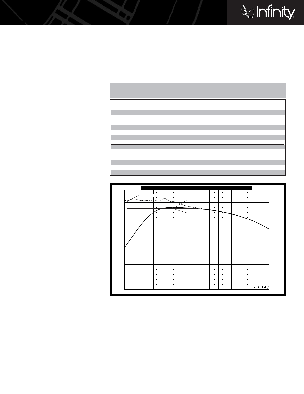
The sample curve below shows typical
in-car and out-of-car frequency response
curves for a Perfect VQ woofer in a
sealed enclosure. The charts that follow
give some sealed enclosure volumes
that may be used for each of the
Perfect VQ woofers. The associated
terms (defined below) describe the
woofer’s performance in the enclosure.
• Vb – Enclosure volume
• F3 –Frequency at which the subwoofer’s
output is attenuated by 3dB
• Fmax – Frequency at which output is at
a maximum
• Ripple – Deviation from flat response
above roll-off
• Insert – Indicates which insert should
be used (LowQ, MidQ or none)
• In-car level @ 20Hz – Indicates level
at the lowest frequency. A positive
number indicates a response that
rises with decreasing frequency and a
negative number indicates a response
the falls with decreasing frequency.
(continued)
20 50Frequency 100 Hz 200 500 1K 2K
Perfect VQ Sealed
dB
95
90
85
80
75
70
65
60
55
IN-CAR LEVEL @ 20Hz)
FMAX (100Hz)
RIPPLE (.3dB)
The highlighted combinations will provide the best compromise between low-frequency extension and
flat response and high-output, and are considered optimum. Higher ripple values indicate a “boomier”
sound and provide higher output at the expense of flat frequency response and low-frequency extension.
Vb (ft^3) F3 (Hz) Fmax (Hz) Ripple (dB) Insert In-Car Level @ 20Hz
Kappa Perfect10 VQ and 10d VQ, Sealed
0.3 58 100 0.3 low –2
0.4 53 100 –1 low 0
0.5 45 80 1 mid 1
0.75 42 90 0 mid 3
135542none 4
infinite baffle 26 90 –0.5 none 11
Kappa Perfect12 VQ and 12d VQ, Sealed
0.4 60 100 2 low –4
0.6 58 100 0 low 0
0.75 47 76 2 mid –2
142620.75 mid 1
1.25 35 50 2 none 3
infinite baffle 20 80 0 none 15
Page 6
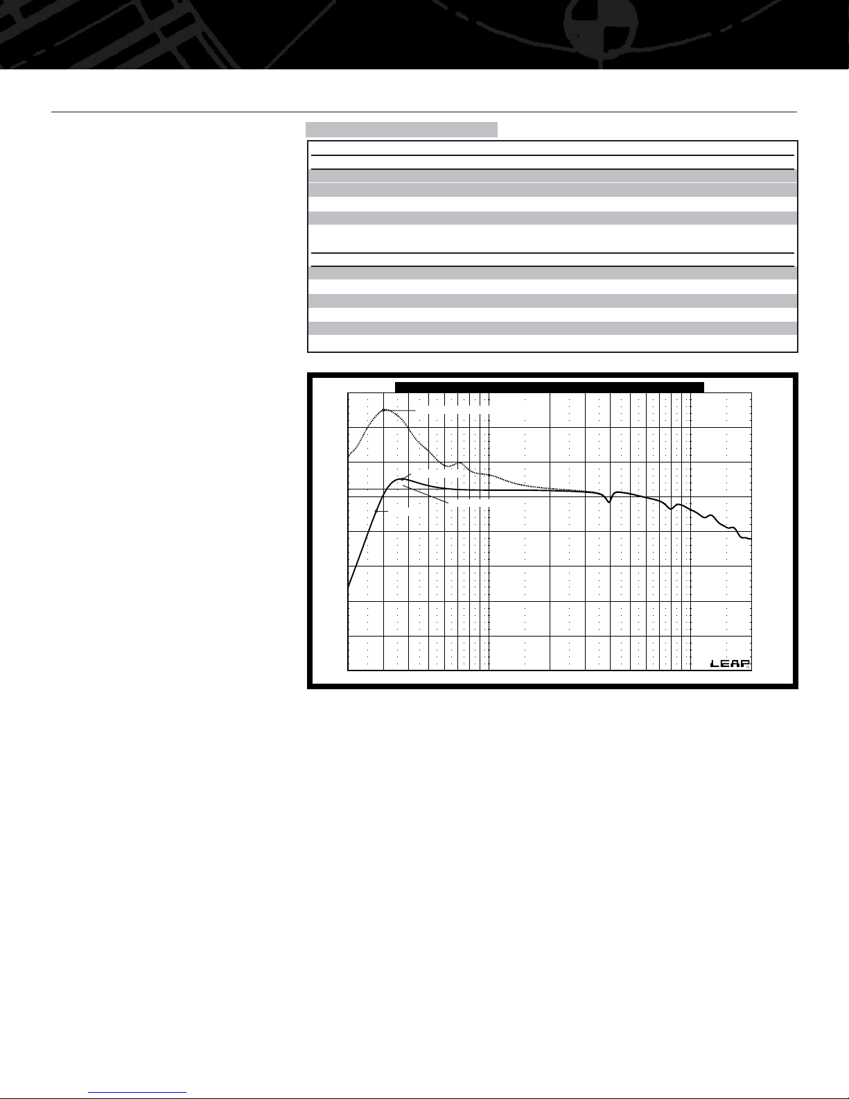
PERFECT VQ IN VENTED ENCLOSURES
Use the sample curve and the charts
at right to choose the vented box that
best suits your application. Some
additional terms used with vented
enclosure specifications are defined
below. We recommend the use of
round, flared ports to minimize
distortion caused by air moving
through the port at high output.
• Pd – Port diameter
• PL – Port length
• In-car Fmax – Vented enclosure and
woofer systems always exhibit a peak
in their frequency response in the car.
This term indicates the frequency of
the peak and its amplitude.
CHOOSING AN APPLICATION AND ENCLOSURE (CONTINUED)
Highlighted combinations are optimum.
6
20 50Frequency 100 Hz 200 500 1K 2K
Perfect VQ Vented
dB
105
100
95
90
85
80
75
70
65
IN-CAR FMAX (11.5dB @ 30Hz)
FMAX (36Hz)
F3 (28Hz)
RIPPLE (1.5dB)
Vb (ft^3) Pd (in) PL (in) F3 (Hz) Fmax (Hz) Ripple (dB) Insert In-Car Fmax (Hz)
Kappa Perfect10 VQ and 10d VQ, Vented
1.25 3 11.5 28 35 3 low +10 @ 30
1.75 3 12 21 27 2 mid +12 @ 25
1.75 3 7.5 27 32 4 mid +13 @ 30
2.5 3 11.5 15 24 2 mid +16 @ 23
2.5 3 9.5 17 25 3 mid +15 @ 25
2.5 3 11 20 21 2 none +16 @ 20
Kappa Perfect12 VQ and 12d VQ,Vented
1.75 4 14.5 27 36 1 low +11 @ 30
2.25 4 14 25 32 1 low +12 @ 28
2.25 4 14 28 38 3 mid +13 @ 30
2.25 4 10.5 30 40 3.5 mid +15 @ 35
34162232 1 mid +15 @ 22
3413 28 35 5 none +16 @ 30
Page 7
7
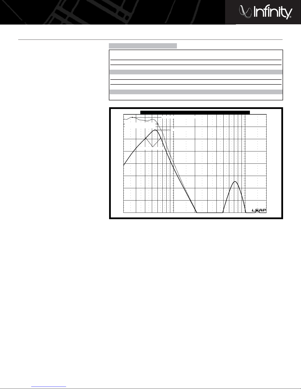
PERFECT VQ IN BANDPASS
ENCLOSURES
Use the sample curve and the charts
that follow to choose the bandpass
box that best suits your application.
Some additional terms used with
bandpass-enclosure specifications are
defined below. We recommend the
use of round, flared ports to minimize
distortion caused by air moving
through the port at high output.
• Vbs – Sealed-enclosure volume
• Vbv – Vented-enclosure volume
• Bandwidth – Indicates the passband
(range of frequencies between the
region of high-frequency attenuation
and the region of low-frequency
attenuation)
• In-car bandwidth – Indicates the
passband with the enclosure
mounted in the car
OTHER APPLICATIONS
Although there are quite a few
enclosures and applications listed here,
there are many other applications that
may suit your preferences. If you have
a computer and enclosure-design
software, the following Thiele and
Small parameters and the aforementioned examples will provide you
with all the information and a starting
point from which you can experiment.
Because the inserts may be installed
and removed repeatedly, you may find
that a particular enclosure may serve
several applications using different
inserts. However, if you are using
several Kappa Perfect VQ woofers in a
single enclosure, the woofers
must all
use identical inserts simultaneously.
CHOOSING AN APPLICATION AND ENCLOSURE
In-Car In-Car
Vbs (ft^3) Vbv (ft^3) Pd (in) PL (in) F3 (Hz) Fmax (Hz) Insert Bandwidth (Hz) Fmax (Hz)
Kappa Perfect10 VQ and 10d VQ, Bandpass
0.6 0.35 3 10 42-82 65 low 20-80 +2 @ 30
0.6 0.35 3 10 40-80 70 mid 20-80 +.5 @ 27
0.6 0.75 4 11.5 35-70 70 none 20-70 +4 @ 35
Kappa Perfect12 VQ and 12d VQ,Vented
11410.5 38-68 51 low 20-60 0 @ 40
21.246.8 40-70 55 mid 20-65 +1.5 @ 26
21.2 4 10 30-63 55 none 20-55 +6 @ 26
20 50Frequency 100 Hz 200 500 1K 2K
Perfect VQ Bandpass
dB
105
100
95
90
85
80
75
70
65
IN-CAR FMAX (+2 @ 27Hz)
FMAX (55Hz)
F3 (42Hz – 56Hz)
IN-CAR BANDWIDTH
(20HZ – 60HZ)
Highlighted combinations are optimum.
Page 8

Infinity Systems • 250 Crossways Park Drive, Woodbury, NY 11797 USA
800.553.3332 • FAX 516.682.3523 • www.infinitysystems.com
© 2002 Harman International Industries, Incorporated • P/N:PERF10/12/dVQOM • Printed 11/02
Declaration of Conformity
We,Harman Consumer International
2, route de Tours
72500 Chateau-du-Loir
FRANCE
declare in own responsibility, that the products described in this
owner’s manual are in compliance with technical standards:
EN 50081-1:1992
EN 50082-1:1997
Emmanuel Millot
Harman Consumer International
Chateau-du-Loir, France.11/02
THIELE AND SMALL PARAMETERS
Perfect10 VQ Perfect10d VQ Perfect12 VQ Perfect12d VQ
Diameter 10" (250mm) 10" (250mm) 12" (300mm) 12" (300mm)
Sensitivity @ 2.83V/1m 87dB 90dB 89dB 92dB
Power Handling 400W RMS/1600W Peak 400W RMS/1600W Peak 400W RMS/1600W Peak 400W RMS/1600W Peak
Frequency Response 25Hz – 400Hz 25Hz – 400Hz 23Hz – 400Hz 23Hz – 400Hz
Impedance per voice coil 4 ohms 4 ohms 4 ohms 4 ohms
Voice-Coil Diameter 3" (77mm) 3" (77mm) 3" (77mm) 3" (77mm)
Mounting Depth 6-1/2" (166mm) 6-1/2" (166mm) 7" (178mm) 7" (178mm)
Overall Diameter 10-1/2" (267mm) 10-1/2" (267mm) 12-3/8" (315mm) 12-3/8" (315mm)
Cut-Out Diameter 9-5/16" (237mm) 9-5/16" (237mm) 10-7/8" (277mm) 10-7/8" (277mm)
Basket Displacement .072 ft^3 (2.04 L) .072 ft^3 (2.04 L) .108 ft^3 (3.06 L) .108 ft^3 (3.06 L)
Voice-Coil DC Resistance Revc 3.32 ohms 1.66 ohms 3.42 ohms 1.66 ohms
Voice-Coil Inductance Levc 1.2mH .8mH 1.14mH .81mH
Driver Radiating Area Sd .344 ft2(.0323M^2) .344 ft2(.0323M^2) .441 ft2(.0491M^2) .441 ft2(.0491M^2)
Motor Force Factor BL w/LowQ Insert 15.05 11.5532 15.55 11.86
w/MidQ Insert 13.05 9.33 12.19 9.6
w/No Insert 10.49 8.1 9.67 8.28
Compliance Volume Vas 1.61 ft3(45.88 L) 1.32 ft3(37.65 L) 3.38 ft3(96.43 L) 3.31 ft3(94.28 L)
Suspension Compliance Cmd 309.68uM/N 254.13uM/N 281.68uM/N 275.39uM/N
Moving Mass, Air Load Mms 153.44g 157.9g 182.7g 189.8g
Moving Mass, Diaphragm Mmd 150.1g 154.56g 176.44g 183.54g
Free-Air Resonance Fs 23.09Hz 25.13Hz 22.19Hz 22.01Hz
Mechanical Q Qms 9.67 10.24 10.29 10.52
Electrical Q Qes w/LowQ Insert .33 .31 .36 .31
w/MidQ Insert .44 .46 .5 .47
w/No Insert .68 .61 .79 .64
Total Q Qts w/LowQ Insert .32 .30 .34 .30
w/MidQ Insert .42 .44 .47 .46
w/No Insert .63 .57 .74 .60
Magnetic-Gap Height Hag 3/8" (10mm) 3/8" (10mm) 3/8" (10mm) 3/8" (10mm)
Voice-Coil Height Hvc 1-11/16" (43.5mm) 1-11/16" (43.5mm) 1-11/16" (43.5mm) 1-11/16" (43.5mm)
Maximum One-Way Linear Excursion Xmax 11/16" (16.75mm) 11/16" (16.75mm) 11/16" (16.75mm) 11/16" (16.75mm)
A valid serial number is required for warranty coverage.
 Loading...