

Owner’s Guide
INTERMEZZO™3.5C
ii
INTERMEZZO 3.5c
THIS INFINITY PRODUCT IS DESIGNED FOR 120-VOLT USE ONLY! FOR
DETAILED SAFETY PRECAUTIONS, PLEASE SEE FOLLOWING PAGE IN THIS
OWNER’S MANUAL FOR “IMPORTANT SAFETY INSTRUCTIONS.”
The lightning flash with arrowhead symbol, within an equilateral triangle, is
intended to alert the user to the presence of uninsulated “dangerous voltage” within
the product’s enclosure that may be of sufficient magnitude to constitute a risk of
electric shock to persons.
The exclamation point within an equilateral triangle is intended to alert the user
to the presence of important operating and maintenance (servicing) instructions in
the literature accompanying the product.
L’éclair avec le symbole de la flèche, placé dans les limites d’un triangel équilatéral est
prévu pour avertir l’utilisateur de la présence de “tension dangereuse” non isolée dans
l’enceinte du produit qui pourrait être d’une importance suffisante pour présenter un
risque d’électrocution aux personnes.
Le point d’exclamation dans un triangel équilateral est prévu pour avertir l’utilisateur
de la présence d’instructions importantes pour les opérations et l’entretien (service)
dans les manuels fournis avec l’appareil.
ATTENTION: POUR EVITER LES CHOCS ELECTRIQUES, INTRODUIRE
LA LAME LA PLUS LARGE DE LA FICHE DANS LA BORNE
CORRESPONDANTE DE LA PRISE ET POUSSER JUSQUAU FOND.
Este destello luminoso con un símbolo de punta de flecha dentro de un triángulo
equilátero tiene el objectivo de alertar al usuario sobre la presencia de “voltaje
peligroso” no aislado dentro de la caja del producto que puede ser de magnitud lo
suficientemente grande para constituir un riesgo de choque eléctrico para las personas.
Este punto de exclamación dentro de un triángulo equilátero tiene el objectivo de
alertar al usuario sobre la existencia de instrucciones operativas y de mantenimiento
(servicio) importantes en la literatura que acomaña el aparato.
CUIDADO: PARA REDUCIR EL RIESGO DE CHOQUE ELÉCTRICO, NO
RETIRE LA CUBIERTA (O RESPALDO). DENTRO NO HAY PEIZAS A LAS
QUE EL USUARIO PUEDE DAR SERVICIO. REMITA EL SERVICIO AL
PERSONAL DE SERVICIO CALIFICADO.
CAUTION
RISK OF ELECTRIC SHOCK
DO NOT OPEN
WARNING: SHOCK HAZARD, DO NOT OPEN.
AVIS: RISQUE DE CHOC ELECTRIQUE – NE PAS OUVRIR.
CUIDADO: PELIGRO DE CHOQUE ELÉCTRICO – NO ABRIR.
CAUTION: TO REDUCE THE RISK OF ELECTRIC SHOCK
DO NOT REMOVE COVER (0R BACK)
NO USER SERVICEABLE PARTS INSIDE
REFER SERVICING TO QUALIFIED PERSONNEL

Read First!
1.Read Instructions.All the safety and operating
instructions should be read before the product is
operated.
2.Retain Instructions.The safety and operating
instructions should be retained for future reference.
3.Heed Warnings.All warnings on the product and in
the operating instructions should be adhered to.
4.Follow Instructions.All operating and use
instructions should be followed.
5.Cleaning. Unplug this product from the wall outlet
before cleaning.Do not use liquid cleaners or aerosol
cleaners.Use a damp cloth for cleaning.
6.Attachments.Do not use attachments not
recommended by the product manufacturer,
as they may cause hazards.
7.Water and Moisture.To reduce the risk of fire or
electric shock,do not use this product outdoors or
near water–for example,near a bathtub,wash bowl,
kitchen sink or laundry tub;in a wet basement; near a
swimming pool;or the like.
8.Accessories. Do not place this product on an
unstable cart,stand, tripod,bracket or table.The
product may fall,causing serious injury to a child or
adult,and serious damage to the product.Use only
with a cart,stand, tripod,bracket or table
recommended by the manufacturer, or sold with the
product. Any mounting of the product should follow the
manufacturer’s instructions,and should use a
mounting accessory recommended by the
manufacturer.
9.A Product and Cart Combination
Should Be Moved with Care.Quick
stops,excessive force and uneven
surfaces may cause the product and
cart combination to overturn.
10.Ventilation. Slots and openings in the cabinet are
provided for ventilation and to ensure reliable
operation of the product and to protect it from
overheating,and these openings must not be blocked
or covered.The openings should never be blocked by
placing the product on a bed,sofa,rug or other
similar surface.This product should not be placed in a
built-in installation,such as a bookcase or rack,
unless proper ventilation is provided or the
manufacturer’s instructions have been adhered to.
11.Power Sources.This product should be operated
only from the type of power source indicated on the
marking label.If you are not sure of the type of power
supply to your home,consult your product dealer or
local power company.For products intended to operate
from battery power,or other sources,refer to the
operating instructions.
12.Grounding or Polarization.This product may be
equipped with a polarized alternating-current-line plug
(a plug having one blade wider than the other).This
plug will fit into the power outlet only one way.This is
a safety feature.If you are unable to insert the plug
fully into the outlet,try reversing the plug.If the plug
should still fail to fit,contact your electrician to
replace your obsolete outlet.Do not defeat the safety
purpose of the polarized plug.
13.Power-Cord Protection.Power-supply cords should
be routed so that they are not likely to be walked on or
pinched by items placed upon or against them,paying
particular attention to cords at plugs,convenience
receptacles,and the point where they exit from the
product.
14.Nonuse Periods.The power cord of the product
should be unplugged from the outlet when left unused
for long periods of time.
15.Outdoor Antenna Grounding. If an outside antenna
or cable system is connected to the product,be sure
the antenna or cable system is grounded so as to
provide some protection against voltage surges and
built-up static charges.Ar ticle 810 of the National
Electrical Code, ANSI/NFPA 70, provides information
with regard to proper grounding of the mast and
supporting structure,grounding of the lead-in wire to
an antenna discharge unit,size of grounding
conductors,location of antenna-discharge unit,
connection to grounding electrodes,and requirements
for the grounding electrode.See Figure A.
16.Lightning. For added protection for this product
during a lightning storm,or when it is left unattended
and unused for long periods of time,unplug it from
the wall outlet and disconnect the antenna or cable
system. This will prevent damage to the product due to
lightning and power-line surges.
17.Power Lines.An outside antenna system should not
be located in the vicinity of overhead power lines or
other electric light or power circuits,or where it can
fall into such power lines or circuits.When installing
an outside antenna system,extreme care should be
taken to keep from touching such power lines or
circuits,as contact with them might be fatal.
18.Overloading. Do not overload wall outlets,extension
cords,or integral convenience receptacles,as this can
result in a risk of fire or electric shock.
19.Object and Liquid Entry.Never push objects of any
kind into this product through openings,as they may
touch dangerous voltage points or short-out parts that
could result in a fire or electric shock.Never spill
liquid of any kind on the product.
20.Servicing. Do not attempt to service this product
yourself,as opening or removing covers may expose
you to dangerous voltage or other hazards.Refer all
servicing to qualified service personnel.
21.Damage Requiring Service. Unplug this product
from the wall outlet and refer servicing to qualified
service personnel under the following conditions:
a. The power-supply cord or the plug has been
damaged;or
b. Objects have fallen onto,or liquid has been spilled
into,the product;or
c. The product has been exposed to rain or water;or
d. The product does not operate normally when
following the operating instructions.Adjust only those
controls that are covered by the operating instructions,
as an improper adjustment of other controls may
result in damage and will often require extensive work
by a qualified technician to restore the product to its
normal operation;or
e. The product has been dropped or damaged in any
way;or
f. The product exhibits a distinct change in
performance; this indicates a need for service.
22.Replacement Parts. When replacement parts are
required,be sure the service technician has used
replacement parts specified by the manufacturer or
that have the same characteristics as the original
part.Unauthorized substitutions may result in fire,
electric shock or other hazards.
23.Safety Check. Upon completion of any service or
repairs to this product,ask the service technician to
perform safety checks to determine that the product is
in proper operating condition.
24.Wall or Ceiling Mounting.The product should be
mounted to a wall or ceiling only as recommended by
the manufacturer.
25.Heat.The product should be situated away from
heat sources such as radiators,heat registers,stoves
or other products (including amplifiers) that produce
heat.
Figure A.
Example of Antenna Grounding as per
National Electrical Code ANSI/NFPA 70
I
MPORTANT SAFETY PRECAUTIONS
iii
INTERMEZZO 3.5c
CAUTION
RISK OF ELECTRIC SHOCK
DO NOT OPEN
The lightning flash with arrowhead
symbol within an equilateral triangle is
intended to alert the user to the presence
of uninsulated “dangerous voltage” within
the product’s enclosure that may be of
sufficient magnitude to constitute a risk of
electric shock to persons.
The exclamation point within an
equilateral triangle is intended to alert the
user to the presence of important
operating and maintenance (servicing)
instructions in the literature accompanying
the appliance.
Antenna Lead-In Wire
Ground Clamp
Antenna Discharge Unit (NEC Section 810-20)
Grounding Conductors (NEC Section 810-21)
Electric Service Equipment
Ground Clamps
Power Service Grounding Electrode System
(NEC Art. 250, Part H)

ii Caution
iii Important Safety Precautions
1 Technology
2 Unpacking the Product/Included Accessories
2 Placement
3 Tilt Adjustment
4 Controls and Connections
6 Maintenance and Service
7 Specifications
Table of Contents
INTERMEZZO 3.5C OWNER
’S GUIDE
iv
INTERMEZZO 3.5c

1
INTERMEZZO 3.5c
Intermezzo Series loudspeakers incorporate several innovative
technologies that,when implemented by exceptional engineering
talent after hours upon hours of subjective listening evaluations,
result in a loudspeaker that realistically and accurately reproduces
the signal source with minimal distortion and coloration.
CeramicMetalMatrixDiaphragms™(C.M.M.D.™)
For decades,loudspeaker engineers have known that the ideal
transducer should be stiff,yet light,and have high internal
damping (damping is a material’s ability to absorb energy).
Infinity’s C.M.M.D.transducer is a significant advance in
transducer technology.Ceramic,a class of material new to
loudspeakers,offers better performance than other materials.
Ceramic is stiffer than metals and lighter than plastics and
typical composite materials;it also offers improved damping.
These ceramic-based transducers take us a giant step closer to
the ever-elusive “ideal transducer.”
In tweeters,C.M.M.D.technology offers stiffness and damping
superior to that of traditional metals and soft-dome materials.
In woofer and midrange applications,it offers accurate pistonic
operation over the entire frequency range of the driver,
completely eliminating coloration due to cone breakup and
dramatically reducing distortion. And when ceramic-metal-matrix
diaphragms are exposed to moisture,sunlight or extreme
temperatures,their performance does not deteriorate.
In addition to ceramic diaphragms,all the transducers incorporate
magnetic shielding and rigid cast-frames that,through our FEA
computer modeling and scanning-laser-vibrometer measurements,
have been optimized to reduce resonances.This ensures minimal
distortion and incomparable performance.
Amplifier
BASH®is an amplifier-power-supply technology that increases
efficiency by reducing power dissipation in the output section.
The BASH topology uses a high-efficiency,fast-response,switchmode power supply that provides the main voltage rails for a
linear Class-AB amplifier.By varying the output of the power
supply with the audio signal being amplified,a constant voltage
drop across the output transistors of the linear amplifier can be
maintained. This means that the power dissipation in the output
transistors is greatly reduced.
The result is an extremely efficient audio amplifier that does not
compromise audio performance.
We hope you enjoyed this brief introduction to the technology
of Intermezzo loudspeakers.If you would like to further explore
their technology and design,please ask your Infinity dealer
for the C.M.M.D.White Paper.The White Paper can also be
downloaded from Infinity’s Web site at www.infinitysystems.com.
TECHNOLOGY

Unpacking the Product
Finish unpacking the speaker and check the
contents.If you suspect damage from transit,report it
immediately to your dealer and/or delivery service.
Keep the shipping carton and packing materials for
future use.
Included Accessories ...
Grille
Decorative
Side Panel
AC Cord
Tilt Adjustment Hardware
2
INTERMEZZO 3.5c
The Infinity Intermezzo 3.5c is designed to offer excellent
performance in any home-theater system.However,the following
placement guidelines and suggestions will start you on your way
to achieving optimum performance.Remember, these are
guidelines.
For best results,place the Intermezzo 3.5c center-channel
speaker either on top of or below the television.Also,position
the speaker so the front grille is even with the TV screen,as
shown in Figure 1.
PLACEMENT
SOFA
LEFT
SURROUND
RIGHT
SURROUND
TV
FRONT
LEFT
FRONT
RIGHT
➢
➢
CENTER
FIGURE 2
– This example shows the Intermezzo 3.5c centerchannel speaker being placed on top of a television.The speaker can
also be placed below the television.
TV
®
FIGURE 1

3
INTERMEZZO 3.5c
For optimum performance,the center-channel speaker should be
directed toward the listening area.Since many televisions are
installed so that the center-channel speaker is well above ear
level,the Intermezzo 3.5c can be tilted downward so it’s aimed at
the listening area.
If you need to tilt the Intermezzo 3.5c,refer to Figure 3 as you
perform the following steps:
1. Open the accessory pack and locate the following items:
three feet (of different lengths),three locking nuts and one
wrench.
2. Lay the speaker upside down and locate the threaded hole on
the bottom.
3. Screw in the appropriate foot for the desired amount of tilt.
4. Tighten the nut with the enclosed wrench.
5. Carefully flip the speaker upright.
TILT ADJUSTMENT
FIGURE 3
– This cross section shows where to install a
foot on the bottom of the Intermezzo 3.5c center-channel
speaker.

4
INTERMEZZO 3.5c
CONTROLS AND CONNECTIONS
Rear Panel
Front Panel
1
AC-Cord Input
2
Power Switch
3
Speaker Input
4
TV Size Selector
5
High-Pass-Filter Selector
6
LED Selector
7
Woofer Level Control
56
120V – 60HZ 6A
AC FUSE
3A 250V
1
2
POWER
CAUTION!
For continued protection
against risk of fire, replace
only with same type fuse
and rating
ATTENTION!
Utilizer un fusible de
recharge de meme
type et calibre
INTERMEZZO 3.5c
3
INPUTS
+
–
4
TV
NONE SMALL LARGE
RISK OF ELECTRIC SHOCK
AVIS RISQUE CHOC ELECTRIQUE – NE PAS OUVRIR
ON
HIGH-PASS
CAUTION
DO NOT OPEN
FILTER
OFF
OFF
ON
LED
ANSIUL-1492
LR106476
7
¢
›
5
INTERMEZZO 3.5c
TV Size Selector
4
This control optimizes the performance of the Intermezzo 3.5c
based on the size of the TV on which it is placed.
If you are placing the Intermezzo 3.5c behind a perforated
screen for a projection TV,set this switch to “None.”
If you are placing the Intermezzo 3.5c on top of a TV with a
diagonal screen size up to about 36," set this switch to “Small.”
If you are placing the Intermezzo 3.5c on top of a TV with a
diagonal screen size larger than 36," set this switch to “Large.”
High-Pass Filter
5
When set to “On,” this control limits the low frequencies that the
Intermezzo 3.5c will reproduce and allows you to use your
processor’s/receiver’s bass-management settings for an ideal
blend with a subwoofer.
When set to “Off,”the Intermezzo 3.5c will reproduce the entire
frequency range.Use this setting only if your system does not
include a subwoofer.
LED Selector
6
This switch determines whether the green power indicator on
the woofer level control 7will illuminate when the speaker is
playing.The setting of this switch does not affect the
performance of the speaker in any way.
Setting the Woofer Level Control
7
1.Set the processor’s/receiver’s center-channel-speaker setting
to “Small.”
2.Confirm correct setting of Set TV Size selector 4.
3.Using the test tones in your receiver/processor,adjust the
center-channel-speaker output (on the processor) to match the
left and right speakers.
4.Finally,fine-tune the level adjustment on the Intermezzo 3.5c
7
to most closely match the tonal balance of the main left and
right speakers.(For the Intermezzo 4.1t,initially set the centerchannel level to “5.” For the Intermezzo 2.6, set to the same
setting as the Intermezzo 2.6’s woofer adjustment.)
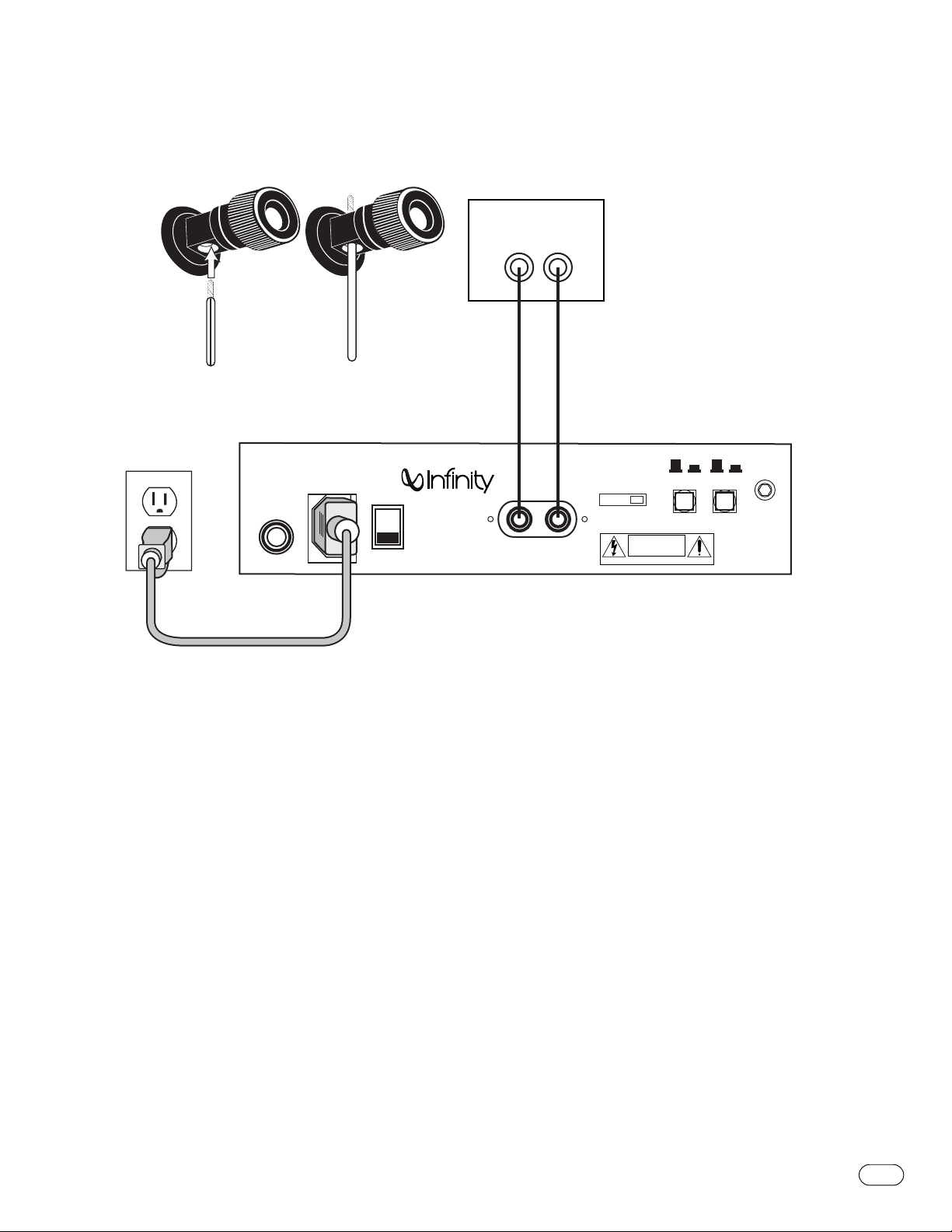
Speaker Connections
3
RED =
+
BLACK =
–
Amplifier/Receiver
Center-Channel
Speaker Outputs
+ –
STRIPE =
1. LOOSEN TERMINALS
2. INSERT BARE END;
TIGHTEN TERMINALS
+
AC FUSE
3A 250V
120V – 60HZ 6A
NO STRIPE =
POWER
AC CORD
–
CAUTION!
For continued protection
against risk of fire, replace
only with same type fuse
and rating
ATTENTION!
Utilizer un fusible de
recharge de meme
type et calibre
OFF
INTERMEZZO 3.5c
INPUTS
+
–
TV
NONE SMALL LARGE
HIGH-PASS
CAUTION
RISK OF ELECTRIC SHOCK
DO NOT OPEN
AVIS RISQUE CHOC ELECTRIQUE – NE PAS OUVRIR
ON
FILTER
OFF
ON
LED
ANSIUL-1492
LR106476

6
INTERMEZZO 3.5c
The Intermezzo 3.5c may be cleaned using a soft cloth,
dampened with water only,to remove fingerprints or to wipe
off dust.
The grille may be gently vacuumed.Stains may be removed with
an aerosol cleaner,following its instructions.Do not use any
solvents on the grille.
All wiring connections should be inspected and cleaned or
remade periodically.The frequency of maintenance depends on
the metals involved in the connections,atmospheric conditions,
and other factors,but once per year is the minimum.
If a problem occurs,make sure that all connections are properly
made and clean.In the event that your Intermezzo 3.5c ever
needs service,contact your local Infinity dealer or Infinity
directly at 1-800-553-3332 or www.infinitysystems.com.
MAINTENANCE AND SERVICE

7
INTERMEZZO 3.5c
Intermezzo 3.5c
Frequency Response: 80Hz – 20kHz (±1.5dB)
60Hz – 22kHz (±3dB)
Nominal Impedance: 8Ω
Sensitivity: 90dB
(2.83V @ 1 meter)
Recommended
Amplifier Power Range: 25 – 150 Watts
Woofer Amplifier Output: 250 Watts RMS
(100Hz with no more
than 0.1% THD)
2nd- and 3rd-Order
Harmonic Distortion: <1%
(20Hz – 20kHz @ 95dB SPL)
Crossover Frequencies: 350Hz,2800Hz; 24dB/Octave
Dimensions: 8-3/4" x 22" x 8"
222mm x 559mm x 203mm
Weight: 27 lb
12.3kg
SPECIFICATIONS
Infinity continually strives to update and improve existing products,as well
as create new ones.The specifications and construction details in this and
related Infinity publications are therefore subject to change without notice.

© 2000 Infinity Systems,Inc.,250 Crossways Park Drive,Woodbury,NY 11797 USA (800) 553-3332 (USA Only) www.infinitysystems.com
BASH is a registered trademark of Indigo Corporation.Infinity is a registered trademark of Infinity Systems,Inc.Printed in USA 3/00 Part No.335717-001
 Loading...