

Page 1
28
+++++++++++++++++++++++++++++++++++++++++++
Warranty Card
Photocopy or tear this page out and send via fax or mail to validate warranty.
Must be returned within 15 days of purchase. Failure to do so voids warranty.
Name:
_____________________________________
Agency:
_____________________________________
Address:
_____________________________________
_____________________________________
City:
______________________ State: _____ Zip Code: ________
Telephone No.: _____________ Email Address:____________________
Product Model No.: ____________ Serial No. : ____________________
Date Purchased: _________ Purchased from: ______________________
Detach and Mail (or fax 303 862 7170): Kirmuss & Associates/Infinity Advanced Technologies
51 West 84th Ave., Suite 301, Denver, Co . USA 80260
© 2005-2015 K&A. Specifications subject to change without notice. Failure to read and
follow the guidelines established in the manual may void warranty. Restricted to Public
Safety, Fire/EMS use. License to operate is required. Customer is solely responsible for
full compliance with local, state, federal and other laws regarding product usage.
Tampering or modifying the unit voids FCC / CE Approval and Warranty.
Model K911AD1
(K911-DVU1 KIT)
FCC Part 90
VHF/UHF ANALOG/DIGITAL
dPMR Portable Transceiver
USER’S MANUAL V2.3
WARNING!
Read the instruction manual completely before use.
Install the antenna first, then the battery.
Charge the battery 14-24 hrs before use even if the green
LED on the charger lights before the recommended time.
This is to condition the battery. DO NOT OVERCHARGE!
Keeping the battery in charger reduces battery life. DO NOT
use radio without the factory approved antenna attached.
USER MUST BE FAMILIAR WITH 2 WAY RADIOS
Failure to perform these steps
may damage the radio and
void the warranty.
Kirmuss & Associates
Worldwide Technologies Direct
Infinity Advanced Technologies
www.wwtechnologiesdirect.com www.kirmussaudio.com
51 West 84th Ave, Suite 301, Denver,, Colorado, USA 80 260 tel:303 263 6353 fax:303 862 7170
Page 2
2
To our Valued Customers:
Thank-you for purchasing an INFINITY two way portable transceiver. This ro-
bust, compact, easy to use radio incorporates the latest technologies providing
reliable performance at an unprecedented low cost. Before operating this radio, please read this manual carefully. Failure to do so may void warranty.
Your radio may have been preprogrammed by your Communications Officer or
Dealer and some of the sections in this manual may not apply.
FCC ID: PODMM-UVF10
FCC NOTICE: This device complies with Part 15 and
Part 90 of the FCC Rules and is listed.
Operation is subject to the following two conditions:
1. This device may not cause harmful Interference.
2. This device must accept any interference received, including interference that may
cause undesired operation.
This equipment generates RF energy and if not installed or used in accordance with the
instructions, may cause harmful interference to radio communications and other devices.
There is no guarantee that interference will not occur. If this equipment does cause harmful
interference which can be determined by turning the equipment on or off or transmitting
momentarily, the user is encouraged to try to correct the interference by one or more of the
following methods:
-Re-orient or relocate the receiving antenna
-Increase the separation between the equipment and the receiver
-Connect equipment into an outlet on a circuit that is different from that to the receiver is
connected
-Consult the dealer or an experienced radio/TV/ communications technician
RADIO FREQUENCY ENERGY SAFETY INFORMATION
This transceiver has been tested an complies with both national and international standards in
regards to Radio Frequency (RF) energy emitted and guidelines regarding human exposure to
RF energy. The radio complies with FCC and IEEE guidelines for occupational use/controlled RF
exposure environments, where duty talk cycles should be limited to 50% talk, 50% listen based
on recommendations by the National Council on radiation Protection and Measurement as well
as the American National Standards Institute.
Reference: FCC OET Bulletin 65, Edition 97-01 Supplement C, ANSI C95.1.1992,ANSI
C95.3.1992, Ministry of Health Canada Safety Code 6
1588 !
We,
Kirmuss & Associates/Infinity Advanced Technologies,
51 West 84th Ave., Suite 301, Denver, Colorado, USA 80260;
Declare that this equipment complies with the essential requirements of the Radio and Telecommunication Terminal Directive, 1999/5/EC, and that any applicable Essential Tests have
been performed.
Description of the Equipment: FM Handheld Transceiver
Model No. K911-AD1/K911-DVU-kit
This compliance is based on conformity with the following harmonized standards or documents:
(1) ETSI EN301 489-1 V1.6.1 (2004-12)
(2) ETSI EN301 489-5 V1.3.1 (2 002-08)
(3) ETSI EN300 086-1 V1.2.1 (2 001-03)
(4) ETSI EN3000 086-2 V1.1.1 ( 2001-03)
(5) EN60950: 2001+A11: 2004
Charles B Kirmuss
Denver, Colorado, USA, 15 January 2015 President
Place and Date of Issue Kirmuss & Associates/Infinity A dvanced Technologies
DECLARATION
OF CONFORMITY
27
Limited Warranty Statement
Infinity warrants this product to be free against defects in materials and
workmanship as follows:
Labor: For a period of two years from date of purchase if this product
is determined by Infinity to be defective, Infinity will repair and/or replace the product with a new or rebuilt unit or repair at no charge. After
the warranty period, you must pay for all labor and parts charges. Customer to ship the radio pre-paid via UPS ground to Infinity for evaluation. Infinity then will credit the UPS costs at its sole option. If the radio
is found to be defective under warranty, Infinity will repair/exchange
per the above policy, sending the unit back freight prepaid to Customer. If found to be a customer caused problem or abused and outside of
above warranty, customer to pay for freight charges to and from factory plus repair charges at current published repair rates.
Parts: If a warranty issue, Infinity to supply at no charge, new or rebuilt
replacements for defective parts for a period of two years. After the
warranty, standard repair or replacement rates apply.
SERVICE: To obtain warranty service, you must communicate with
Infinity directly, and then once an RMA Return Materials Authorization
Number is received, to ship it back in its original carton, or in packaging offering an equal degree of protection, to Infinity, freight prepaid
with insurance.
This warranty does not cover the battery which has a one year pro-
rated warranty, nor does it cover customer instruction, installation, set up, programming, adjustments or signal reception or transmission.
This warranty does not cover any units which have been previously
altered, repaired, or serviced by anyone other than Infinity or used with
accessories not approved by Infinity. This warranty does not cover
cosmetic damage or damage due to acts of god, accident, misuse,
negligence, or modification to any part of the product
This warranty does not cover products sold AS-IS or with FAULTS.
No particular merchantability of this product is implied or stated.
Proof of purchase in form of a bill of sale or receipted invoice, evi-
dence that the unit is within the warranty period must be presented to
obtain warranty service. Warranty is offered only if Warranty Card has
been sent out within 15 days of purchase to Infinity. Detach card from
manual. This warranty is invalid if the factory serial number applied
has been altered or removed from the Product. Re-Sellers may have
additional Warranty Statements
REPAIR OR REPLACEMENT AS PROVIDED UNDER THIS WARRANTY
IS THE EXCLUSIVE REMEDY OF THE CONSUMER. INFINITY SHALL
NOT BE LIABLE FOR ANY INCIDENTAL OR CONSEQUENTIAL DAMAGES FOR BREACH OF ANY EXPRESS OR IMPLIED W ARRANTY ON
THIS PRODUCT EXCEPT TO THE EXTENT PROHIBITED BY APPLICABLE LAW. ANY IMPLIED WARRANTY OR MERCHANTABILITY OR FITNESS FOR A PARTICULAR PURPOSE ON THIS PRODUCT IS NOT
MADE OR IMPLIED BY INFINITY.
Page 3

26
14.0 Taking Care of your handheld Transceiver
Your transceiver has been designed using the latest in technology
along with high temperature flame retardant plastics. Normal regular care an attention will increase the longevity of certain components.
Handle your radio with care.
Do not carry the transceiver by either the antenna or the op-
tional external speaker microphone.
When the speaker microphone or other accessory is not in
use, keep the speaker microphone accessory jacks covered
by using the supplied flap that is attached to the radio.
To clean, use a moistened rag with a mild detergent, and with
a nearly dried cloth, clean the case, control knobs, and keypad. Never use any chemicals to clean the unit.
Regularly, wipe the battery contacts with a lint-free cloth to
remove dirt, grease, or any other materials that may prevent a
good electrical connection.
Never Expose the Radio to direct sunlight, heat or cold for ex-
tended periods of time.
3
OPERATIONAL INSTRUCTIONS & SAFETY GUIDELINES
RF ENERGY EXPOSURE IS DETERMINED PRIMARILY BY
THE DISTANCE TO, AND THE POWER OF, THE TRANSMITTING DEVICE. In general, RF exposure is minimized when the low-
est possible power is used and transmission time is kept to a minimum
consistent with effective communications and the antenna is at the
furthest possible distance from the body. Users should transmit no
more than 50% of the time and follow the guidelines:
To Transmit and Receive: You must be properly licensed by
the FCC or your governing radio communications authority
to use this radio on the programmed frequencies.
To Transmit, first hold down the MON (Monitor) button if so pro-
grammed for a moment to make sure that the channel is not busy with
other traffic that you may not hear this depending on the TONE that
may be programmed in shared transceivers if the channel is a shared
frequency with other users with different CTCSS/CDS Tones. You may
also look at the received signal strength meter (green light) is off) to
ensure that the channel is clear.
To transmit: Push and hold the Push– to-Talk (PTT) Button; speak in a
normal voice. There is a 1/4 second delay before the radio transmits
as the RF output to the antenna is tuned to the frequency/channel being used.
To Receive, release the PTT button.
Hand-held Transceiver Operation:
Hold the radio in a vertical position with the radio approximately 1.5 to
2.5 “ away from your lips.
Body Worn Application:
As in most cases whenever using an approved case and body pack for
this transceiver or not, use of this radio with the antenna touching the
body may exceed the FCC RF exposure guidelines.
Antennas & Batteries
Use only Infinity supplied and approved antennas and batteries.
Use of non approved accessories and attachments as well as
user modifications could not only damage the radio and void
warranty, but also may void FCC and CE regulations as well as
exceed RF exposure limits. DO NOT OVERCHARGE BATTERIES. Keeping the battery in the charger continually reduces battery life. Consult Infinity or your Authorized Reseller/ Distributor
if you have any questions.
Page 4
4
User Precautions: Safety, Warranty and Use
The following will assist you in fulfilling any warranty obligations.
Do Not Modify this radio for any reason. Do not disassemble the radio.
Failure to comply may void Warranty and governmental approvals. No
User Serviceable Parts inside. Refer repair to Factory Authorized Personnel only.
Do Not Use the transceiver or charge the battery in an explosive envi-
ronment.
Keep the transceiver out of direct sunlight, DO NOT expose the unit to
extreme heat or cold.
Keep the transceiver out of dusty or humid areas. IF IMMERSED IN
WATER, TAKE OUT OF WATER AND BLOW AIR ACROSS THE
SPEAKER AND SHAKE ANY WATER THAT MAY BE TRAPPED IN
FRONT OF THE SPEAKER GRILL.
Do Not Transmit without an approved antenna connected to the trans-
ceiver. Install the battery only after the antenna is connected to the
radio. Fully charge the battery first to condition it.
Observe common sense when attempting to transmit in areas such as
construction sites, mines, hospitals, hazardous environments, etc..
Turn off your radio before entering any area with a potentially
explosive atmosphere (where the air contains gas, dust), as well as
while taking on fuel, etc.).
Typically transmit for no longer than 1 minute with a rest period of 4
minutes. Longer transmission times will see the rear side of the radio
heat up.
If the radio emits smoke or strange odors, turn the radio off, discon-
nect the battery and promptly contact your local authorized Infinity
Dealer or Re-Seller.
About your radio: Infinity radios are sold only through Infinity or Au-
thorized Resellers. The radio is also field programmable using the key-
pad, software, or wired cloning (if enabled by the software); and may
come pre-programmed with either factory defaulted programming or
other User channels. Full function access to the radio and options is
only available if the optional Infinity programming software with the appropriate interface cable has been purchased. The sale and use of
these radios is restricted to licensed users only. User takes the responsibility to comply with FCC and other governmental or local requirements. CONDITION OF SALE: The User is familiar with radio opera-
tions, radio configuration and radio terminology. It is im por tant
that the User is aware of and understands hazards common to the operation of any radio transceiver. Thank-you for selecting the K-911 for
your radio communications needs!
25
13.0 PROGRAMMING VIA SOFTWARE Your radio comes pre-
programmed with some channels for test. The Programming kit comes with a
USB cable, Programming Software and a USB cable driver for WIN XP and
Win7,(Model PG-12). (For Win 8, Order Model PG-13.) PC SKILLS AS WELL
AS FAMILIARITY WITH TWO RADIOS ARE NECESSARY. You will need to
unzip the files provided using a free program called WINRAR from WIN RAR
LABS and is available as a free download from the Internet. When downloading,
just download only the free unzip program. In preparation for programming:
(1) Load (unzip) the USB driver onto the PC. Install the USB driver.
(2) Load (unzip) the Programming Software onto your PC.
(3) Restart the PC.
(4) Connect the supplied USB driver to an available port on the PC
(5) Check with Windows device manager that the USB cable is operating and
seen by the PC
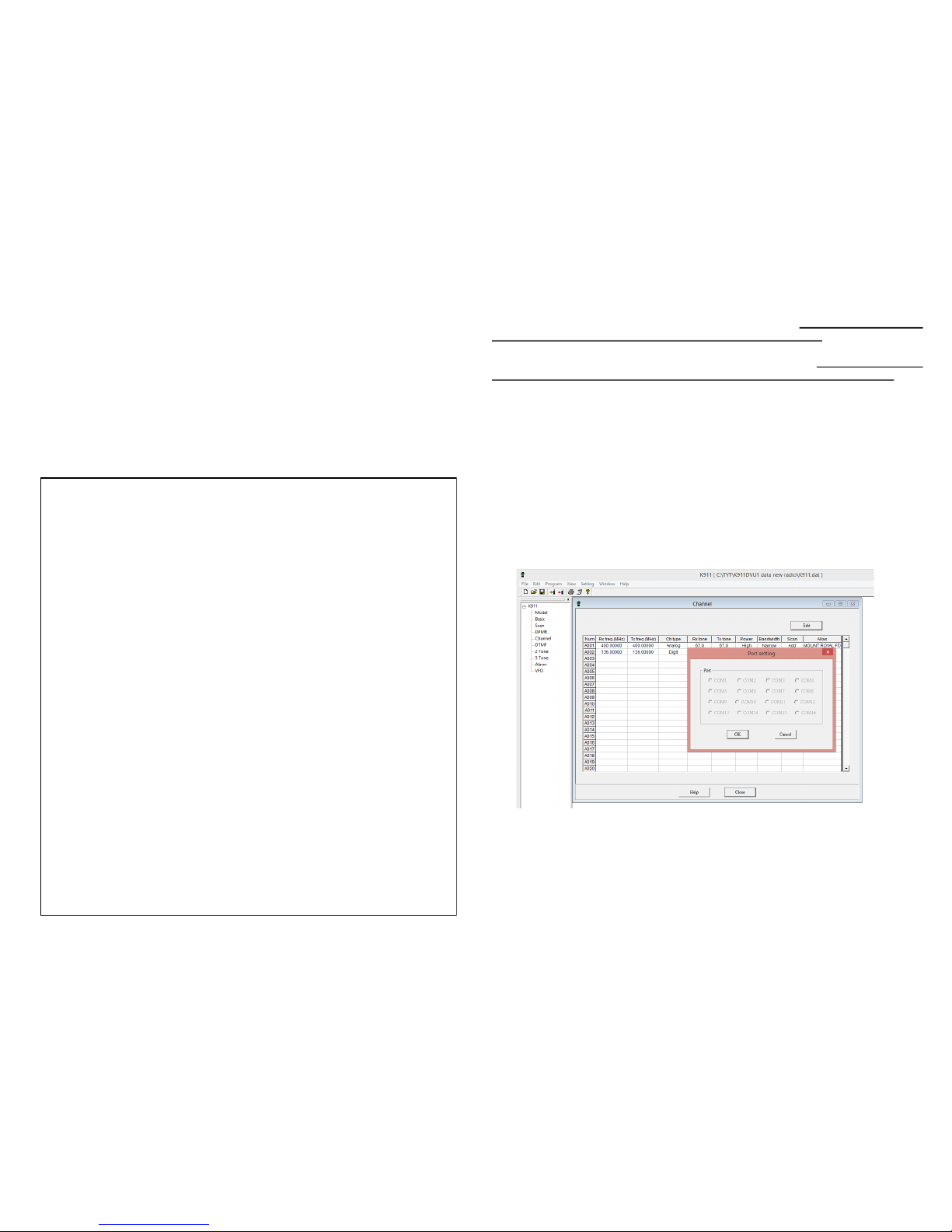
(6) START the programming software by clicking on the K-911 Icon that is on
your desktop, placed automatically by extracting the software from the executable file. THE FOLLOWING SCREEN APPEARS:
(7) CLICK ON SETTING; PORT. A POP UP SCREEN WILL APPEAR WITH
THE PORT NUMBER CORRESPONDING TO THE USB CABLE. (example,
COM 5). THEN PRESS OK. IF NO PORT NUMBER APPEARS, CHECK
WINDOWS DEVICE MANAGER TO MAKE SURE THAT THE USB CABLE
DRIVER (PROLIFIC) HAS BEEN SUCCESSFULLY INSTALLED.
(8) WITH RADIO ON AND CABLE CONNECTED, THEN perform a “READ
FROM RADIO, then save the file, NAMING IT AS AN EXAMPLE, “ORIGINAL
FILE”.
(9) THEN make changes as needed, then SAVE THE FILE, EXAMPLE, AS
‘MASTER 1 FEB 2015”, THEN WRITE TO RADIO.
COM 5
Page 5

24
12.2 Receive CTCSS/DCS (QT and QDT) functions that have been
programmed by your dealer or your communications specialist will allow
you to hear radio traffic only when the these sub-audible signaling tones
have been heard from another similarly programmed radio by your receiver. Only then will the radio allow you to receive a transmission of the
same tone. If tone decoding is not used or programmed in the transceiver, then all conversations on the programmed frequency will be heard.
12.2 Radio ANI ID is a feature that transmit s a unique ID
number that has been programmed into your radio. This allows all
radios in this group to see each other. Then program each individual radio with an ANI Code (number that corresponds to the radio
call of the user), with end of transmission selected. Each radio
has a unique number. Using this feature may or may not affect the
receipt of some repeater based ID transmissions and may not
work with all Motorola MDC1200 systems. Test first to evaluate
the situation. Also set up in digital signaling for dPMR digital
mode.
12.3 Receive CTCSS/DCS (QT and QDT) functions that hav e been
programmed by your dealer or your communications specialist will allow
you to hear radio traffic only when the these sub-audible signaling tones
have been heard from another similarly programmed radio by your re-
ceiver. Only then will the radio allow you to receive a transmission of the
same tone. If tone decoding is not used or programmed in the transceiver, then all conversations on the programmed frequency will be heard.
12.4 Talkaround. Thi s function is enabled by the user in situations where the user does not want to trip the repeater but have
local ground operation conversations to local responders and not
be heard over the repeater network.
First select your channel. This must be a repeater channel.
PRESS THEN THE ASSIGNED HOT KEY AS PROGRAMMED IN
THE PROGRAMMING SOFTWARE. To cancel and return to normal repeater operations: Press the HOT KEY button.
USING THE TALKAROUND FUNCTION will see all Radio units
that are in close proximity to your area of operations hear you on
the repeaters output frequency as you are transmitting and receiving on the repeater output frequency. They also, as well as you,
will hear the repeater. The corresponding CTCSS/DCS tones will
also follow automatically. This is not to be confused with
“Reverse” hot key operation, which simply inverts the TX and
RX frequencies and tones. (See Page 12). Consul t your Com-
munications Officer for details.
5
K-911 Main Product Features at a Glance:
The K-911 is a 128 channel x 2 transceiver with 2 channel groups
(zones), (A and B), and features a 5 watt (VHF), 4 watt (UHF) power output with both analog and with digital dPMR capability. (dPMR is very
similar to NXDN protocol implementation by Kenwood and Icom; both
now offer dual-standard equipment (July 2013). Users are expected to be
familiar with these modes and has on hand a communications officer to
support these radios. Programming and radio se up requires some radio
knowledge. Having said this, using the Programming Software, one can
immediate “get on the air” while exploring the radio’s other capabilities of
this radio. Software is needed for many of the features.
Noted features:
2 Tone/5 Tone/DTMF Decode and Encode (Pager Function)
2.5/6,25/12.5/25 KHz narrow/wide band spacing w/2.5 KHz Channel
step
ANI ID code/dPMR signaling (check compatibility with your radio
system)
VOX operation (for hands free operation)
LCD Color TFT display with channel, frequency or English language
channel alias, with or without access to frequency list.
Audio Compander X-Pander improves audio quality when in narrow-
band mode.
Programmable by software with PC and/or Front Keypad* [*Keypad
programming access may be locked out by the software.]
Wired Cloning capable
50 CTCSS ands 104 DCS Normal/Inverted tones,
Selectable
Time-out-Timer (TOT)
Busy Channel Lock-out (BCL)
Battery Fuel Gauge and Low Battery Alert
Remote Kill, Remote Stun if programmed
dPMR compatible digital
Page 6

6
Step 1: Unpacking (Kit contents)
Unpack the contents of the shipping carton carefully. We recommend that
you identify the items listed below before discarding the packing material.
You may also have additional accessories inserted in the box, such as an
extra rechargeable battery, speaker/microphone, ear mic., PC Programming Software CD, PC programming cable, etc., depending on your order.
If any damage has occurred during shipment, contact the Carrier.
If there are any missing parts, please contact the Re-Seller immediately.
Parts List
Gain Flex Antenna
Rapid
Battery
Charger
AC
Adapter
2 Way Radio
Transceiver Rechargeable
Lo-Poly Battery
STEP 2. Transceiver Preparation Before Use.
>NOTE: The factory does not charge the battery before shipping.
Follow all instructions precisely.
2.1 Insert the supplied rubber washer onto the an-
tenna connector before attaching the antenna.
Screw the supplied antenna with the SMA female
connector onto the mating top connector of the
transceiver by holding the radio with one hand and
then grasping the base of the antenna with the other,
then turning the antenna clockwise until secure.
DO NOT OVER TIGHTEN! The antenna should be snug.
Radio mounted
belt clip, 2 screws
23
Page 7

22
67.0 XZ 71.9 XA 74.4 WA
77.0 XB 79.7 WB 82.5 YZ
85.4 YA 88.5 YB 91.5 ZZ
94.8 ZA 97.4 ZB 100.0 1Z
103.5 1A 107.2 1B 110.9 2Z
114.8 2A 118.8 2B 123.0 3Z
127.3 3A 131.8 3B 136.5 4Z
141.3 4A 146.2 4B 151.4 5Z
156.7 5A 162.2 5B 167.9 6Z
173.8 6A
NO TONE CSQ
CTCSS Motorola CTCSS Motorola CTCSS Motorola
CONVERSION CHART FOR CTCSS TONES WITH
OLDER SYSTEM TINE NOMENCLATURE
11.0 ANALOG OPERATING NOTES:
Your transceiver is 2 and 5 tone , DTMF paging receive
and encode capable.
For 2 Tone Paging Radio Operation,
either for Decoding (receive) or Encoding (creating a 2 tone
transmission), you will need to use the
Optional Paging Radio Software, as these functions are not
keypad field programmable.
You will need also to find out and make note of the “A” and
“B” Tones for your paging system, and their spacing as it
applies to your radio system for successful 2 tone decode
(or encode) operation.
HINT: For u se with commonly used MOTOROLA Minitor pag-
ing systems, the following settings should be used:
-First delay: 0.5 (length of first tone)
-Second Delay: 0.5 (length of second tone)
-Interval Time: 2.0 (time between tones A & B)
-Long Delay: 5.0 (when creating a page, (Encode mode only),
this is the time that radio waits once PTT is pushed to send out
7
2.1 To Install the Battery Pack:
Locate the battery pack on top of the rear of the
transceiver as shown.
Then per (2) slide the battery pack towards the
top of the transceiver. The battery will lock into
place. Tug on the battery to make sure that it is
properly mated to the radio.
2.2 To Remove the Battery from the Trans-
ceiver:
Use your thumb to press down on the battery
release ass shown (1) , then slide the battery
downwards to remove.
Then pull the battery away from the transceiver.
2.3 Combination Battery/Belt Clip:
Typically the belt clip is not mounted to the ra-
dio.
Locate the belt clip and the two screws supplied
as part of your kit.
2.4 Attaching the Programming Cable or external speaker microphone accessory.
The radio comes with the accessory connector
covered by a rubber flap.
If you are using an accessory device such as
the optional MIC-5 Speaker microphone or GPS
LCD Mic or desire to program the radio with the
optional Programming Cable:
Page 8

8
2.5 Radio Preparation, First Time Battery Charging
The radio transceiver comes with a 17.4 V, 1,800 mAH Lithium
Polymer Rechargeable battery. Charge the battery for the first
time between 11 and 14 hours before use, even if the green
LED indicator lights up before this time has elapsed. T
Charger Indicator Status
The charger has 3 LED status indicator lights.
Red: The battery is charging.
Green: -AC Power is connected. (no battery inserted)
-There is no battery installed.
-Battery is fully charged.
Flashing Red: Battery Failu re, can not charge battery.
Any Color, Dim LED:
The battery is damaged and may not be charged.
The charger may be used to charge either the radio with
Battery installed or battery alone.
For subsequent charges, charge until the Green LED
appears.
OTHER NOTES:
(i) Prolonged charging may reduce battery life.
(ii) Do not use unapproved battery chargers: Infinity batteries
and chargers form an integrated charging system.
(iii) The radio has a built-in battery gauge. When a single bar
appears or there is no bar, the battery needs recharging.
(iv) Never disassemble the battery.
(v) Do not throw into a fire or expose
or short circuit the connections.
(vi) Lithium batteries may be
recycled. Do not dispose of as
garbage.
(vii) Do not charge battery in a hazardous location
(viii) Do not short circuit the terminals.
21
About dPMR digital Private Mobile Radio 6.25 kHz Technology
Since the beginning of PMR radio, there has been a constant juggling act between available spectrum and channel size. As filter and
modulation technology has advanced the channel size has progressively reduced, 100 kHz, then 50, followed by 25 and then the 12.5
kHz we have known for the last twenty or so years. Add to that the
current policy of spectrum pricing and it becomes clear that a new
advance was needed to make the most efficient and economical
use of this scarce resource.
Traditionally PMR has always operated with FDMA technology as
that has offered the best flexibility to users. The initial plan for European standardization was based on 2-slot TDMA technology as several of the major PMR players have proffered that 6.25 kHz FDMA
was simply not possible. Research by Icom and Kenwood however
showed that 6.25 kHz FDMA was a practical proposition and they
entered into a joint agreement to develop the technology further.
This new digital 6.25 kHz FDMA idea was taken up by ETSI (the
European Telecommunications Standards Institute) and developed
into a European Standard. dPMR became an open, non-proprietary
EU standard and was published under the reference TS 102 490
(License-free) and TS 102 658 (Licensed).
Your K-911 radio operates in Analog as well as in both dPMR digital conventional and digital trunking modes. To enable backwards
compatibility, they also operate in 25 kHz and 12.5 kHz channel
bandwidths. Backwards compatibility to analog only radios enables
a planned migration path to “digital” with existing radios operating
analog only and new radios operating analog and digital as soon as
industry standards and norms evolve.
Therefore your radio is dPMR ready. Functions etc. are all
software defined by the programming software.
Page 9

20
9
Technical Specifications
Frequency 136 ~ 174 MHz
400 ~ 520 MHz
RF Power Output (at 7.2VDC):
VHF: 5 Watts
UHF: 4 Watts
Low Power setting 0.5 Watts
Frequency Stability: Better than +/- 2.5 ppm
Modulation Distortion: Better than 3%
Spurious emissions: Better than 70 dB
Audio Power Output: 1 Watt balanced, less than 5% THD
Modulation 16KФF3E/11KФF3E
Number of Channels 128 x 2
Max Freq. Deviation: , 5KHz VHF; ,2.5 KHz UHF
Channel Spacing 25 kHz/ 20 kHz/ 12.5kHz/ 6.25 kHz
Sensitivity (12 dB SINAD): Better than –122 dBm
Squelch Activation Sensitivity: Better than 0.18 microV
Adjacent Channel Selectivity:
VHF: Greater than 68 dB
UHF: Greater than 65 dB
Adjacent Channel Selectivity: Better than 85 dB
Spurious Response Rejection: Better than 65dB
Spurious radiation: <5 microW
Battery Voltage: 7.2V Cathode Grounding
Current Draw (at 7.5 VDC):
Receive: less than 400 mA
Standby: less than 30 mA
Transmit: Less than 1.6A Operating 5W
Temperature: -25 deg C~ +55 deg C
Antenna Impedance: 50Ω
Microphone Impedance: 2.2kΩ
Battery (Standard): Model Batt-12, Li-poly Battery
DC 7.4V , 1800mAh
Battery Operation: 9—14 hours (5:5:90 cycle)
Dimensions (W×H×D) : 61 mm X106 mm X33 mm
Weight: 400g(with battery and antenna)
NOTE:
Specifications subject to change without prior notice.
Page 10

10
3.0 Getting Familiar with Your Radio Controls
Key
Numeric
de 1) User Definable
de
12
Channel
Knob
port
14 Key
Key
16
)
Key
enhanced convenience request to
Consult the programming soware menu for available opons.
short press
Turns on and o LCD screen
(6)
(12)
(13)
19
9.3 TOT (Time-out Timer)
The Time-out timer can prevent a User from occupying a certain
channel for an extended period of the time or prevent a charnel being
occupied by a radio that has it’s PTT held down accidently (radio in
back pocket). Once the TOT time has been reached, the 2 way radio
will stop transmitting and a warning tone will be sounded alerting the
user of this. TOT reset. This is the time delay after the PTT key has
been released and the PTT button will return active (normal mode).
9.4 Auto Battery Power Saving
If this function is enabled, 10 seconds after no signal is received or no
User operation is carried out, the radio will be in the power-saving
mode. When any signal is received or any operation is carried out, the
radio can automatically quit this mode. Power-saving modes: 1: 1, 1:
2, 1:4 and off. Setting the power-saving function of a battery can reduce the power consumption of the battery.
9.5 Busy Channel Lockout (BCL)
If the busy channel lockout has been activated, transmitter activation
is prohibited on a channel that is busy channel. If one presses the
PTT button to transmit and with the channel occupied, the unit’s
speaker will sound a “busy channel lockout" tone, and where the User may not activate the transmitter.
Lock Out Settings for flexibility: (i) Carrier wave: If there is a carrier
on the channel, radio transmission (PTT) is inhibited. (ii) Lock out on
Carrier wave + CTCSS/ QT/DQT/DCS: If there is both a carrier
wave on the tuned channel with a valid CTCSS/QT/DQT/DCS match-
ing PL tone, transmission (PTT) is allowed.
8.3.6 Remote kill/remote stun
This is programmed via software, if a radio is lost or stolen, and if the
radio received a remote Kill Code: it will be disabled.
If it received a stun code, it will receive but not transmit.
Page 11

18
9.0 COMMON USER OPERATIONS
Operation:
TO Setting:
11
4.0 List of Hot Key (short cuts) available
Key
Enable
YOUR RADIO’S HOT KEYS
Write in the keys as programmed for future
reference. Defaults may change without
notice.
Side Key 1:
Long Press: _______________
(default: MONITOR/MONI )
Short Press: _______________
(default: MONITOR/MONI )
Side Key 2:
Long Press: _______________
(default: TALKAROUND)
Short Press:_______________
(default: BACKLIGHT)
Front Panel Function Key 1:
Long Press; _______________
(default SCAN )
Short Press: _______________
(default: NONE)
Front Face Function Key 2:
Long Press:________________
(default : VFO)
Short Press:________________
(default: NONE)
Note 1: REVERSE and TALKAROUND
NEED TO BE ENABLED IN THE CHANNEL
EDIT SCREEN IN THE PROGRAMMING
SOFTWARE
Page 12

12
5.0 About Radio Operations.
5.1 Terminology.
In a wireless Land Mobile Radio (LMR) Communications system, there are
two modes of operation: DIRECT (communicating on the same transmit and
receive frequency between radio users, sometimes called Radio to Radio,
Car to Car, or SIMPLEX); and over a REPEATER (where a portable or mobile radio transmits on one frequency and receives on another).
In DIRECT/SIMPLEX MODE, there may be obstacles such as buildings or
uneven terrain affecting the transmission over long distances of communications between two or more low power (ex. 5 watt) portable radios. In a REPEATER configuration, a radio receiver and high power radio transmitter
(example 50 to 150 watts) with two antennas is located on a mountain top or
elevated location.
When using a handheld radio the Repeater due to its better elevated location and higher output power, it receives much better the low power signal of
the hand held or other radio units. Once received, the transmitter retransmits
simultaneously the received radio transmission from the handheld or mobile
radio on a frequency that differs from the received signal at higher power.
When strategically located on top of a high building or a mountain top, the
Repeater can greatly enhance the performance of a wireless network by allowing communications over distances much greater than would be possible
without it. In this case coupled with higher power, the Repeater “repeats” the
communications from the hand held or mobile unit that it receives, and increases the range due to the higher power and better antenna and location
of this relay station.
TIP: Using “Talkaround” feature: When Teams do no t have a simplex
private channel to work with and only have a repeater channel available,
some radios such as this K911 may allow you to preprogram a hot key to set
the repeater channel into TALKAROUND mode. In this setting the repeater
stays the same but radios set to TALKAROUND will transmit and receive on
the repeater’s output. (“A”). This only works if both users are within range of
each other as no repeater is used. In this fashion field units will also hear
the repeater’s transmissions and may respond if needed by turning TALKA-
ROUND off.
Repeater
Receive: 156.090 MHz, “B” Transmit: 154.875 MHz, “A”
When it Receives a signal the repeater transmits what it receives
Portable Unit 1
Receive: 154.875 MHz. “A”
Transmit: 156.090 MHz, “B”
Portable Unit 2
Receive: 154.875 MHz, “A”
Transmit: 156.090 MHz, “B”
Repeater Operation
17
8.2 IN DIGITAL CHANNEL MODE: tree as follows:
Page 13

16
8.0 User MENU Options via Front Keypad
Below is the Programming Tree as it looks when one accesses
the various enabled (default) user accessible functions. The
List, Sequence, etc. may change depending
on software configurations made by user or
firmware revision level).
Highlight using select button, then rotate the
channel selector or use UP—DOWN key.
8.1 IN ANALOG CHANNEL MODE: tree as foll ows
13
5.2 About Sub-Audible QT (Quiet Tones)
(CTCSS) and Digital Sub-Audio (DQT / DCS)
Tones
QT or CTCSS (Continuous Tone-Coded Squelch System is a
circuit found in a two way radio transceiver that is used to reduce
the annoyance of listening to other users on a shared two way
radio system where more than one user group is on the same
channel and frequency, (called co-channel users). Using CTCSS
or QT filters out other users if they are using a different CTCSS/
Qt tones, or no CTCSS. DQT or DCS is called Digital Coded
Squelch, similar to CTCSS.
Example: One may have bot h the Fire Dept. and EMS on the
same frequency. During standard operations, one may not want
to hear the other. The two-way radio receiver's audio turns on
only in the presence of the correct sub audible tone that only the
radio hears that corresponds to the respective agency’s programmed sub-tone. Therefore in this application, Fire uses one
sub- tone, EMS another. Conventional radios without CTCSS (or
CTCSS turned off, or seeing the User pressing the MONI button
on the K-911 would hear all transmissions from both groups. The
Firefighters would have to listen to the radio traffic from EMS
while EMS would hear all conversations from Fire.
If the radios are programmed with 2 different CTCSS tones on
two different channels using the same frequency, units from
each group would only hear radios from their own Department
that are programmed to the same CTCSS or DCS code number
of their group. Using this also reduces missed messages and the
distraction of unnecessary radio traffic from the other Agency.
There are many other uses for CTCSS/DCS often called PL
TONES (Motorola term) or Channel Guard. (A GE term).
Prior to programming a radio one therefore needs to mark
down the following:
-Receive Frequency
-Receive Tone (If CSQ is written, there is no tone used)
-Transmit Frequency
-Transmit Tone
-Whether the radio is to operate in narrow or wide band
-The channel alias associated with the particular radio
channel
This information should be available from your communications
officer.
Page 14

14
6.0 Basic Transceiver Operation-Quick Guide
To Turn the Transceiver On: With the antenna connected and bat-
tery inserted, rotate the power/volume control knob clockwise. The color LCD screen will come on with “INFINITY” as the defaulted start up
screen. In start up option, Battery Voltage may also appear if selected.
The radio will display the channel number and channel alias for both
banks of the radio, A and B. 128 channels per bank.
Increase or Decrease Volume as needed. If there is no one on frequency and nothing is heard from the unit’s speaker, you may adjust volume
by pressing the MONITOR button (opening up the squelch), and then
adjusting the volume level as needed. See Page 15, Section 7.1 for
preprogrammed Channel Defaults from the Factory.
Squelch: The transceiver has a preset squelch level which may be
adjusted (in the Squelch set-up/programming mode either in the software or by using the front keypad. To do so USING THE RADIO: with
the LCD screen lit and to the lower left hand coroner, the word “MENU”
will be present. Press the [ — ] key immediately below the word
“MENU”. Rotate the channel selector going thought the various menus
that appear until you see “RADIO SET”. Press the [ — ] button below
the word “SELECT” and rotate the channel selector once more until you
see the word “SQL LEVEL” appears on the screen. Press the [ — ]
once more and select the entry. SQL level 9 closes the squelch level
threshold, while SQL level 1 opens up the squelch. Select as desired.
Press [ — ] BACK repeatedly to exit and save.
This should be set to “5” for normal operation.
Transmitting: It is common practice to hold down the MONITOR but-
ton momentarily (Button “SK2”, Page 10), to open up the squelch and
defeat the CTSS/DCS tone that may have been programmed to avoid
transmitting while another station using another CTCSS or DCS tone is
on your radio frequency but not on your tone. If this is the case, you
may also consult the “receive signal bar meter” that also shows relative
receive signal strength. If another station is on frequency you will see
the received signal on this bar graph. Also is there is another station
the GREEN LED on the unit will also light up. If the MONI button would
be pushed, ( you would then hear the other station.)
Consult your communications officer for use of the this formality and
see if it applies to your agency. Transmit only when the channel is
clear. If the radio was set up for BCL (Bust Channel Lock out), a Beep
will be heard from the radio speaker indicating that the channel is occupied, and will not allow you to turn the transmitter on using the PTT key
until the channel is clear.
15
7.0 To Access Keypad controlled functions
Your K-911 has been programmed at the factory with defaulted channels and certain
functions that are enabled at the factory. Many may be changed by way of accessing
the Main Menu Options per bank and channel. Select the bank, then the channel,
then access the MENU OPTIONS as described below.
HOLDING DOWN THE KEY WILL ALLOW YOU TO CHANGE THE
BANKS/ZONE ON THE LINE SELECTED.
7.1 RADIO FREQUENCY AND CHANNEL FACTORY DEFAULTS: (check
with your Agency as the radio may have been preprogrammed).
SAMPLE ZONE/BANK A:
SAMPLE ZONE BANK/B:
CH Description Rx Freq Rx Tone Tx Freq Tx Tone
1 V-FIRE/FERN1 154.28 NONE 154.28 156.7
2 V-FIRE 25 154.2875 NONE 154.2875 156.7
60 NWS .400 162.4 NONE NONE NONE
61 NWS .425 162.425 NONE NONE NONE
62 NWS .450 162.450 NONE NONE NONE
63 NWS .475 162.475 NONE NONE NONE
64 NWS .500 162.500 NONE NONE NONE
65 NWS .525 162.525 NONE NONE NONE
66 NWS .550 162.550 NONE NONE NONE
1 V-FIRE/FERN1 154.28 NONE 154.28 156.7
2 V-FIRE 25 154.2875 NONE 154.2875 156.7
10 U-TAC 1/41/TR 453.4625 156.6 453.4625 156.6
 Loading...