

Infinity HPS-500 Service manual
PRELIMINARY
SERVICE MANUAL
HPS 500
POWERED SUBWOOFER
Infinity Systems Incorporated
250 Crossways Park Dr.
Woodbury, New York 11797

- CONTENTS -
SPECIFICATIONS ………….………….….………………………………………..2
SET-UP GUIDE ………………….…………………………………..…………..3
CONTROLS …………………….………….……………………………………….6
OPERATION ………..…..………………………….…………..……………..7
PARTS LIST ………………..………….…………………………………………….9
SCHEMATICS ………..……...…………………………….…………………...16
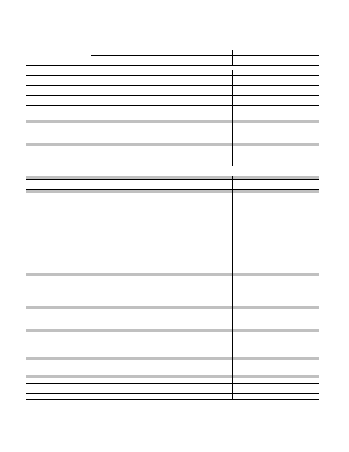
Infinity HPS-500 500w Powered Sub Amp SPECIFICATIONS
Frequency respose
22Hz - 120Hz
Drive Unit
15" Woofer
160 (direct),
Weight 77.2 lbs./35kg
Dimensions (H x W x D)
LINE VOLTAGE 120VAC/60Hz
LINE VOLTAGE 230VAC/50Hz
Parameter Specification Unit Limits Conditions Notes
Amp Section
Type (Class AB, D, other) AB Bridged -- -- BASH® Power Supply
Load Impedance (speaker) 20 Ohms -- Nominal Z-curve required
Rated Output Power 500 Watts
THD@ Rated Power 0.1 %
THD @ 1 Watt 0.3 %
Polarity 0 deg.
DC Offset 20 mV-DC
Damping factor >200 DF --
Input Sensitivity
Input Frequency 31 Hz
Line Input 350 mVrms
Speaker/Hi Level Input 8 Vrms
Signal to Noise
SNR-A-Weighted 100 dBA
SNR-unweighted 70 dBr
SNR rel. 1W-unweighted 60 dBr
Residual Noise Floor 2 mVrms
Residual Noise Floor 1.5 mVrms(max)
Input Impedance Line Input 3k ohms
Speaker/Hi Level Input 470 ohms
Active Filters
Low Pass (fixed or variable) Variable Note: Center positon = 100Hz
Low Pass filter (point or range) 45-120 Hz ±2dB
Slope 12 dB/Octave n/a
Q 0.707 Damping n/a
Normal-Direct Switch yes --
400
1
1
0° ±20
50
31
±2dB
±2dB
90
70
55
3
2
N/A
N/A
functional
1 input driven
22k filter 500w
22k filter
In phase at 50Hz in Direct Mode .250 faston (+)……205 faston (-)
@ Speaker Outputs
Nominal Freq. 1 input driven
To Rated Power 1 input driven
To Rated Power (-26dB below Line In)...1 input driven
relative to rated power A-Weighting filter
relative to rated power 22k filter
relative to 1W Output 22k filter
Volume @max, using RMS reading DMM/VOM (or A/P)
Volume @max, w/ A/P Swept Bandpass Measurement (Line freq.+ harmonics)
Low Pass filter (point or range)
Subsonic filter (HPF) 31 Hz
Video Boost Switch yes -- --
Features --
Limiter
Line Out Crossover Switch
Phase Switch -Line Output (80Hz HPF-unity gain) -Volume pot Taper (lin/log) log --
Input Configuration -- -Line Out: 80/120/160Hz HPF 80/120/160 Hz
Power on Delay time >3 sec.
Transients/Pops
ATO Transient
Turn-on Transient 500 mV-peak
Turn-off Transient 500 mV-peak
Efficiency
Stand-by Input Power 10 Watts
Power Cons.@rated power 670 Watts
Protection
Thermal Protection yes
DC Offset Protection yes
Line Fuse Rating 6 Amps functional Type-T or Slo Blo External fuse with UL/SEMKO rated holder
45-120 (normal)
Slope 12 dB/Octave --
Q -- Damping --
Slope 12 dB/Octave --
Q -- Damping --
Boost +3 dB --
Range 40-80 Hz --
Slope 6 dB/Octave
Q 0.707 Damping
Hz
10
mV-peak
±2dB
±2dB
functional
functional
functional
functional
functional
functional
>3
20
1v-pp
1v-pp
15
N/A
functional
functional
AC Power Applied
@ Speaker Outputs
@ Speaker Outputs AC Line cycled from OFF to ON
@ Speaker Outputs AC Line cycled from ON to OFF
@ nom. line voltage
@ nom. line voltage
Decreases gain at 113°C -1.3dB
DC present at Speaker Out leads Relay or crowbar (for driver/fire protection)
2
CONNECTING YOUR SUBWOOFER
If your receiver/processor does not have subwoofer outputs for the left and right channels:
+
—
+
++
—
——
L
L
R
R
INPUTS
OUTPUTS
B-LINK
™
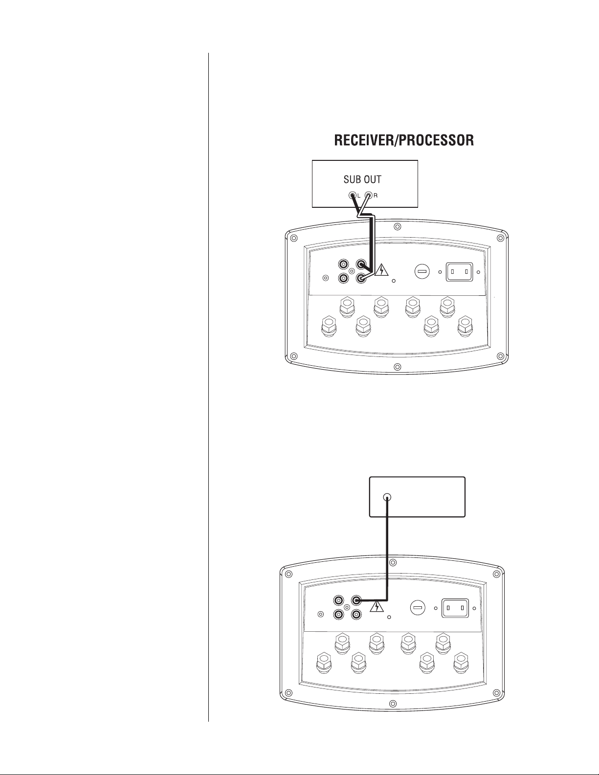
CONNECTING YOUR SUBWOOFER (Continued)
If your receiver/processor has subwoofer outputs for the left and right channels:
If you have a Dolby* Digital or DTS
®
receiver/processor with a low-frequency-effect
(LFE) output:
NOTE: Some receivers have a single
subwoofer output (do not confuse this
with a single LFE output as described
below). In that case, it is recommended
that you use a Y connector (not included)
to maximize performance.
NOTE: In this case, you do not need to
use a Y connector. Simply connect the
LFE output on your receiver/processor
to either the left or right input on
the subwoofer.
HIGHPASS
OUTPUT
120Hz
160Hz
80Hz
LOW
LEVEL
OUT
LOW
LEVEL
IN
L
R
120Hz
160Hz
80Hz
HIGHPASS
OUTPUT
LOW
LEVEL
OUT
SUBWOOFER OR
LFE OUTPUT
LOW
LEVEL
IN
L
R
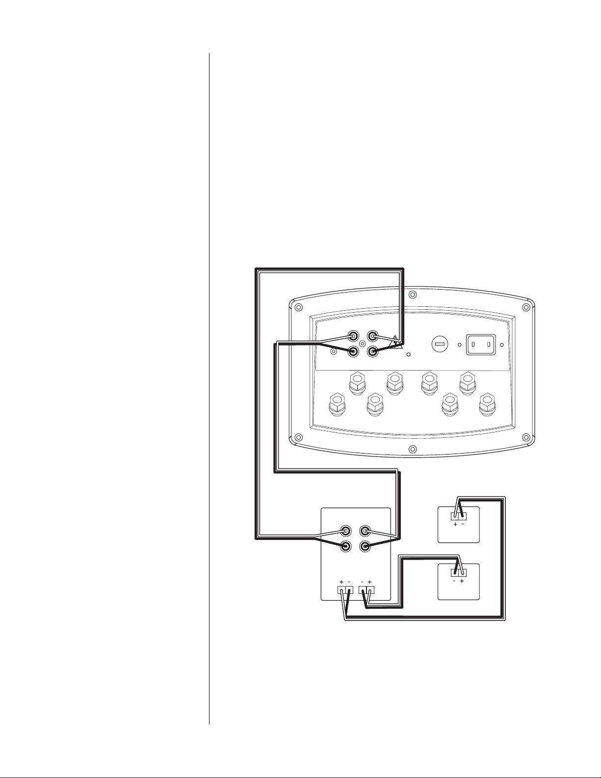
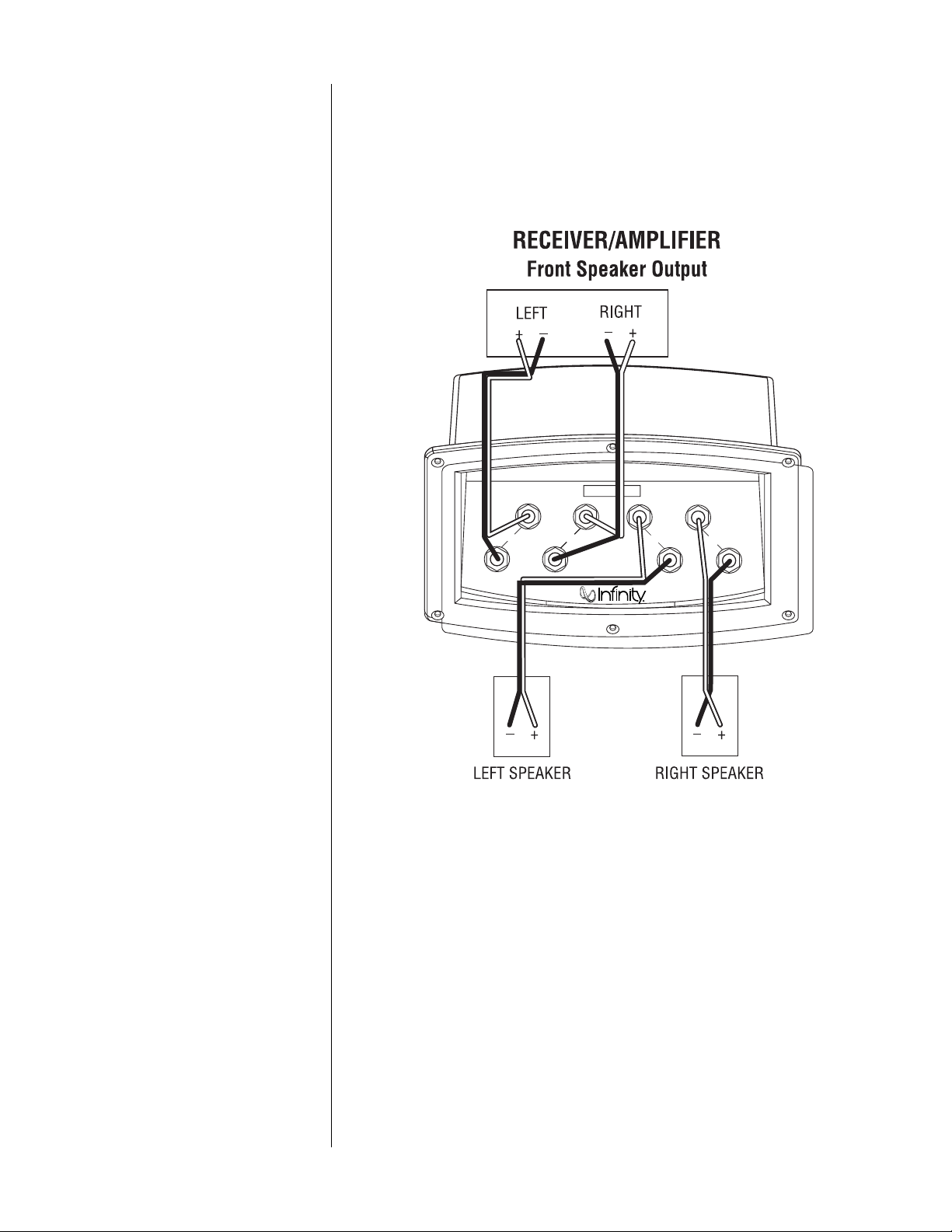
If your receiver/amplifier has preamp output jacks and main input jacks for the left and
right channels or you have a separate preamp/processor and power amplifier:
This method of hookup can offer the highest level of performance for your complete loudspeaker
system. Your subwoofer incorporates an adjustable high-pass crossover in addition to a variable
low-pass crossover. When hooked up as shown below, the subwoofer will limit the low-frequency
information that is returned to your receiver/amplifier. Your receiver/amplifier does not need to
waste valuable power reproducing the low frequencies. In addition, since no low-frequency
information is being sent to your main loudspeakers, they are able to reproduce mid and high
frequencies with greater clarity.
LOW
LEVEL
OUT
LOW
LEVEL
IN
L
R
120Hz
160Hz
80Hz
RECEIVER/AMPLIFIER
OR PROCESSOR/AMPLIFIER
LEFT
RIGHT
RIGHT LEFT
LEFT
LOUDSPEAKER
RIGHT
LOUDSPEAKER
PRE
OUT
MAIN
IN
MAIN SPEAKER
OUTPUT
HIGHPASS
OUTPUT
C
ONTROLS
...
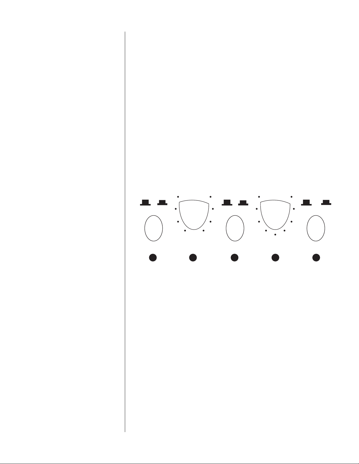
Figure 2.
IDENTIFICATION OF FRONT PANEL CONTROL
(Refer to Figure 2.)
1. EQ: Optimizes subwoofer performance for audio or video playback.
2. Crossover: Controls the frequency below which the subwoofer will begin working.
3. Phase: Reverse/normal switch changes audio-signal polarity.
4. Gain: Controls subwoofer volume level.
5. Input: Switches between the normal line/speaker inputs and the direct-LFE input.
EQ PHASE INPUT
CROSSOVER GAIN
150 50 10 0
AUDIO VIDEO
0˚
180˚ NORMAL DIRECT
1 2 3 4 5
100

12◆ HPS-500/1000 – Owner’s Manual
SETC
ONTROLS
...
P
OWERON
…
A
DJUSTGAIN
…
C
ROSSOVERADJUSTMENTS
…
P
HASECONTROL
...
OPERATION
1. Initially set the HPS’s Gain control to the “O” position.
2. Initially set the HPS’s Crossover control to the 100Hz position.
3. Plug your HPS’s AC cord into a wall outlet. Do not use the outlets on the back of the receiver.
4. Turn on your HPS sub by pressing the power button on the center of the front panel.
5. Turn on your entire audio system and start a CD or movie sound track at a moderate level.
6. Turn your HPS’s Gain control (Figure 2) up to the “5” position (half way). If no sound
emanates from the subwoofer, check the AC-line cord and input cables. Are the connectors
on the cables making proper contact? Is the AC plug connected to a “live” receptacle? Has
the power button been pressed to the “on” position? (Note: A green indicator on the front
panel will light when the power is on.) Once you have confirmed that the subwoofer is
active, proceed by playing a CD, record or cassette. Use a selection that has ample bass
information.
7. Set the overall volume control of the preamplifier or stereo to a comfortable level. Adjust
the subwoofer’s Gain control (Figure 2) until you obtain a pleasing blend of bass. Bass
response should not overpower the room but rather be adjusted so there is a harmonious
blend across the entire musical range. Many users have a tendency to set the subwoofer
volume too loud, adhering to the belief that a subwoofer is there to produce lots of bass.
This is not entirely true. A subwoofer is there to enhance bass, extending the response of
the entire system so the bass can be felt as well as heard. However, overall balance must
be maintained or the music will not sound natural. An experienced listener will set the
volume of the subwoofer so its impact on bass response is always there but never obtrusive.
8. Crossover Control (Figure 2) – The Low-Pass control determines the highest frequency
at which the subwoofer reproduces sounds. If your main speakers can comfortably reproduce
some low-frequency sounds, set this control to a lower frequency setting, between
50Hz – 100Hz. This will concentrate the subwoofer’s efforts on the ultradeep bass sounds
required by today’s films and music. If you are using smaller bookshelf speakers that do
not extend to the lower bass frequencies, set the low-pass crossover control to a higher
setting, between 120Hz – 150Hz.
9. The Phase Control (Figure 2) determines whether the subwoofer speaker’s piston-like
action moves in and out with the main speakers, 0˚, or opposite the main speakers, 180˚.
Proper phase adjustment depends on several variables such as room size, subwoofer
placement and listener position. Adjust the phase switch to maximize bass output at the
listening position.
10. The EQ switch, located on the front panel, optimizes the subwoofer's performance for
both movie and music listening. When in the “Video” position, a special EQ circuit is
activated, enhancing low frequencies by approximately 3dB at 32Hz and delivering the
full impact and excitement of today’s movie soundtracks. When in the “Audio” position,
the subwoofer provides the accurate and linear frequency response that is ideal when a
natural tonal balance is desired for music listening.
11. Remember: every system, room and listener is dif ferent. Ther e are not necessarily any right
or wrong settings; any setting you choose will result in excellent performance. Should you
decide to fine-tune your system for optimum performance, be patient and trust your ears.
It will be worth the effort involved to fully “tweak” your system.
4
4
2
3
 Loading...