

Infineon iMOTION EVAL-M3-TS6-665PN User Manual

AN2017-43 EVAL-M3-TS6-665PN User Manual
EVAL-M3-TS6-665PN User Manual
iMOTION™ Modular Application Design Kit
About this document
Scope and purpose
This application note provides an overview of the evaluation board EVAL-M3-TS6-665PN including its main
features, key data, pin assignments and mechanical dimensions.
EVAL-M3-TS6-665PN is a complete evaluation board including PFC integration discrete IGBT and Gate driver for
motor drives application. In combination with control-boards equipped with the M3 30pin interface connector,
like EVAL-M3-102T
drives.
The evaluation board EVAL-M3-TS6-665PN was developed to support customers during their first steps
designing applications with discrete IGBTs and gate drivers.
Intended audience
This user manual is intended for all technical specialists working with the EVAL-M3-TS6-665PN board.
and EVAL-M3-188. It features and demonstrates Infineon’s discrete technology for motor
Table of Contents
About this document ....................................................................................................................... 1
Table of Contents ........................................................................................................................... 1
1 Safety precautions ......................................................................................................... 3
2 Introduction .................................................................................................................. 4
3 Main features ................................................................................................................ 5
3.1 EVAL-M3- TS6-665PN board specifications ............................................................................................ 7
3.2 Pin assignments ...................................................................................................................................... 9
4 Getting Started with EVAL-M3-TS6-665PN ....................................................................... 11
4.1 Setting up the system ........................................................................................................................... 11
4.2 iMOTION™ development tools and software ....................................................................................... 13
4.2.1 MCEWizard setup overview .............................................................................................................. 13
4.2.2 MCEDesigner setup overview .......................................................................................................... 15
5 Hardware description of EVAL-M3-TS6-665PN .................................................................. 17
5.1 Boost PFC section using IGBT and diode ............................................................................................. 17
5.1.1 AC Voltage sensing and MCEWizard configuration ......................................................................... 18
5.1.2 Hardware Modification for AC Voltage sensing to work with IRMCF188 ........................................ 19
5.1.3 PFC External Current feedback configuration and calculation...................................................... 19
5.1.4 PFC Overcurrent protection circuit and PFC Gatekill configuration .............................................. 20
5.2 Inverter section using six discrete IGBTs and three gate drivers ........................................................ 22
5.2.1 DC-Link Voltage Measurement ........................................................................................................ 23
5.2.2 Motor External Current feedback configuration and calculation .................................................. 24
5.2.3 Inverter Overcurrent protection and Motor Gatekill configuration ............................................... 27
5.2.4 Overtemperature Hardware Protection Circuit .............................................................................. 28
5.2.5 Auxiliary power supply ..................................................................................................................... 29
5.2.6 PFC stage schematic ........................................................................................................................ 30
User Manual Please read the Important Notice and Warnings at the end of this document <Revision 1.0>
www.infineon.com
<2019-06-05>

EVAL
-M3-TS6-665PN User Manual
iMOTION™ Modular Application Design Kit
Safety precautions
5.2.7 Inverter stage schematic ................................................................................................................. 31
5.2.8 Auxiliary stage schematic ................................................................................................................ 32
5.3 PCB Layout ............................................................................................................................................ 33
6 Bill of Materials of Eval-M3-TS6-665PN ............................................................................ 37
7 Reference .................................................................................................................... 40
Revision History ............................................................................................................................ 41
User Manual 2 <Revision 1.0>
<2019-06-05>

EVAL
-M3-TS6-665PN User Manual
iMOTION™ Modular Application Design Kit
Safety precautions
Attention: The ground potential of the EVAL-M3-TS6-665PN system is biased to a
negative DC bus voltage potential. When measuring voltage waveform by
oscilloscope, the scope’s ground needs to be isolated. Failure to do so may result in
personal injury or death. Darkened display LEDs are not an indication that capacitors
have discharged to safe voltage levels.
Attention: EVAL-M3-TS6-665PN system contains DC bus capacitors which take time to
discharge after removal of the main supply. Before working on the drive system, wait
three minutes for capacitors to discharge to safe voltage levels. Failure to do so may
result in personal injury or death. Darkened display LEDs are not an indication that
capacitors have discharged to safe voltage levels.
Attention: Only personnel familiar with the drive and associated machinery should
plan or implement the installation, start-up and subsequent maintenance of the
system. Failure to comply may result in personal injury and/or equipment damage.
Attention: The surfaces of the drive may become hot, which may cause injury.
Attention: EVAL-M3-TS6-655PN system contains parts and assemblies sensitive to
Electrostatic Discharge (ESD). Electrostatic control precautions are required when
installing, testing, servicing or repairing this assembly. Component damage may
result if ESD control procedures are not followed. If you are not familiar with
electrostatic control procedures, refer to applicable ESD protection handbooks and
guidelines.
Attention: A drive, incorrectly applied or installed, can result in component damage
or reduction in product lifetime. Wiring or application errors such as under sizing the
motor, supplying an incorrect or inadequate AC supply or excessive ambient
temperatures may result in system malfunction.
Attention: Remove and lock out power from the drive before you disconnect or
reconnect wires or perform service. Wait three minutes after removing power to
discharge the bus capacitors. Do not attempt to service the drive until the bus
capacitors have discharged to zero. Failure to do so may result in personal injury or
death.
Attention: EVAL-M3-TS6-665PN system is shipped with packing materials that need to
be removed prior to installation. Failure to remove all packing materials which are
unnecessary for system installation may result in overheating or abnormal operating
condition.
1 Safety precautions
In addition to the precautions listed throughout this manual, please read and understand the following
statements regarding hazards associated with development systems.
Table 1 Precautions
User Manual 3 <Revision 1.0>
<2019-06-05>
EVAL
-M3-TS6-665PN User Manual
iMOTION™ Modular Application Design Kit
Introduction
M
HVIC
30 pin iMOTION
TM
MADK-M3 connector
Disc rete IGBT X6
Inverter Section
Line
Neutral
15V
PWM
VFO
Itrip
PWM
VTH
GK
DCBsense
15V & 3.3V
HVIC:IRS44273L
IGBT:IKB20N65H5
PFC Section
PFC
Overcurr ent
protection
Overcurrent and
Overtemperature
protection
PFC
Gatekill
VAC+
VAC-
PFC_Shunt+
PFC_Shunt-
Power
Supply
I_Shunt+
I_Shunt-
Gate
Dri ver
PFC_PWM
EMI Filter
& Soft
Power Up
Circuit
IGBT
IRS2890DSx3
2 Introduction
The EVAL-M3-TS6-665PN evaluation board is a part of the iMOTION™ Modular Application Design Kit for motor
drive (iMOTION™ MADK).
The MADK platform is intended to use various power stages with different control boards. These boards can
easily be interfaced through the iMOTION™ MADK-M3 30 pins interface connector to control board such as
EVAL-M3-102T.
This evaluation board is designed to give Easy-to-use power stage based on the Infineon's discrete IGBT. The
board is equipped with all assembly groups for sensorless field oriented control (FOC). It provides a singlephase AC-connector, rectifier, a PFC inductor, Boost PFC and 3-phase output for connecting the motor. The
power stage also contains emitter shunts for current sensing and a voltage divider for DC-link voltage
measurement.
The EVAL-M3-TS6-665PN evaluation board is available through regular Infineon distribution partners as well as
on Infineon's website. The features of this board are described in the design feature chapter of this document,
whereas the remaining paragraphs provide information to enable the customers to copy, modify and qualify
the design for production according to their own specific requirements.
Environmental conditions were considered in the design of the EVAL-M3-TS6-665PN. The design was tested as
described in this document but not qualified regarding safety requirements or manufacturing and operation
over the whole operating temperature range or lifetime. The boards provided by Infineon are subject to
functional testing only.
Evaluation boards are not subject to the same procedures as regular products regarding Returned Material
Analysis (RMA), Process Change Notification (PCN) and Product Discontinuation (PD). Evaluation boards are
intended to be used under laboratory conditions and by trained specialists only.
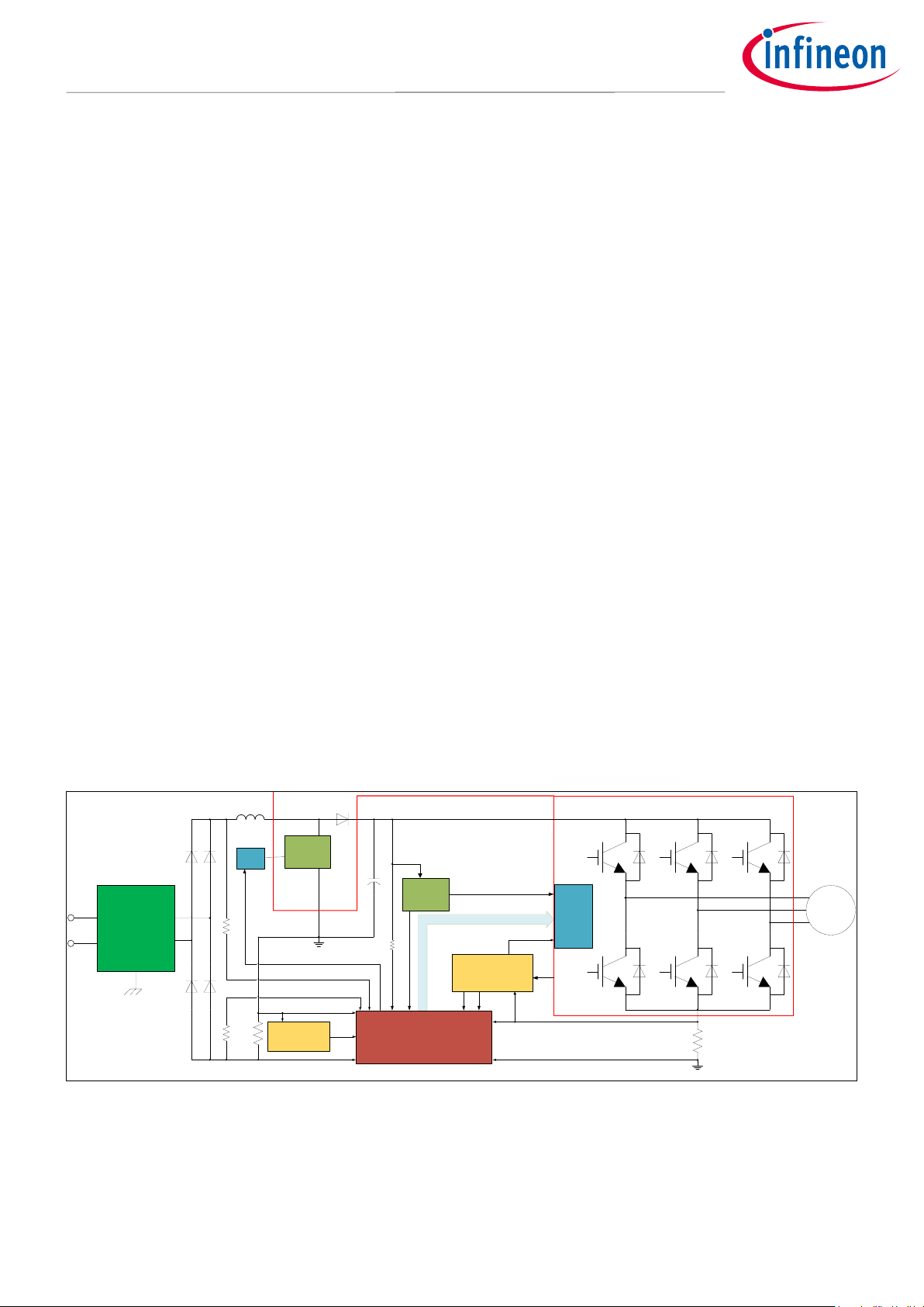
The block diagram of the EVAL-M3-TS6-665PN is depicted in Figure 1. This evaluation board includes an EMI
filter and soft power up circuit, 30 pins iMOTION™ MADK-M3 interface connector, auxiliary power supply to
provide 15 V and 3.3 V, PFC gate driver circuit and the discrete IGBT.
Figure 1 The Block Diagram of the EVAL-M3-TS6-665PN
The hardware circuit regarding overtemperature and overcurrent protection is also included in this power
board. The sense connection to common emitter shunt resistor is connected to the 30 pins iMOTION™ MADKM3 interface connector.
User Manual 4 <Revision 1.0>
<2019-06-05>

EVAL
-M3-TS6-665PN User Manual
iMOTION™ Modular Application Design Kit
Main features
3 Main features
EVAL-M3-TS6-665PN is an evaluation board for motor drives applications. It is integrating a single phase PFC
and 3 phase inverter. It can be combined with one of the available MADK control board to demonstrate
Infineon’s motion control IC and discrete technology for motor drive.
M
ain features of IKB20N65EH5
• Best-in-Class efficiency in hard switching and resonant topologies
• Plug and play replacement of previous generation IGBTs
• 650 V breakdown voltage
• Low Qg
• IGBT copacked with RAPID 1 fast and soft antiparallel diode
• Maximum junction temperature 175°C
are:
Main features of IRS2890DS
• Floating channel designed for bootstrap operation
• Fully operational to +600 V
• Tolerant to negative transient voltage, dV/dt immune
• Gate drive supply range from 10 V to 20 V
• Undervoltage lockout for both channels
• Matched propagation delay for both channels
• Integrated bootstrap functionality
• Overcurrent protection and fault reporting
• Integrated deadtime protection
• Shoot-through (cross-conduction) protection
• Adjustable fault clear timing
M
ain features of IRS44273L
• Low side gate driver
• Gate drive supply range from 10.2 V to 20
• Unde
• 1.5A output current capability
rvoltage lockout
are:
are:
V
User Manual 5 <Revision 1.0>
<2019-06-05>

EVAL
-M3-TS6-665PN User Manual
iMOTION™ Modular Application Design Kit
Main features
The evaluation board characteristics are:
• Input voltage 160~265 VAC
• Maximum 270 W (with heatsink) motor power output
• Power Factor Correction
• On board EMI filter
• Current sensing with single shunt
• Auxiliary power supply with 15 V, 3.3 V
• Overcurrent protection
• Sensing of DC-link voltage
• Thermistor output
• Measurement test-points compatible to standard oscilloscope probes
• PCB is 100 mm × 110 mm and has two layers with 35 μm copper each
• RoHS compliant
User Manual 6 <Revision 1.0>
<2019-06-05>

EVAL
-M3-TS6-665PN User Manual
iMOTION™ Modular Application Design Kit
Main features
Parameters
Values
Conditions / comments
Input
Voltage
1.2A
input 220 VAC, Ta=25°C
Output
Power (3phases)
1.6 A
input 220V
, f
=6 kHz, Ta=25°C, Th=80°C
DC Bus Voltage
Maximum DC bus voltage
120 V
Switching Frequency
PFC switching frequency f
Inverter switching frequency
f
PWM
Current feedback
PFC current sensing resistor R1
100 mΩ
Inverter current sensing resistor
RS
100 mΩ
RS is the IPM inverter section’s common
emitter current sensing resistor.
Protections
threshold divider resistor R17.
Output current trip level
5.5A
peak
Configured by changing shunt resistor R18.
Temperature trip level
100 °C
For controller board EVAL-M3-102T
On board power supply
15 V
15 V ± 5 %, max. 50 mA
Used for gate driver and LDO
3.3 V
3.3 V ± 2 %, max. 20 mA
Supplying the 3.3V to the controller board and
protection circuits
PCB characteristics
Material
FR4, 1.6mm thickness, 2
35 µm copper thickness
Dimension
100 mm x 110 mm
System environment
Ambient temperature
From 0 to 50°C
Non-condensing, maximum RH of 95 %
3.1 EVAL-M3- TS6-665PN board specifications
Table 2 depicts the important specifications of the evaluation board EVAL-M3-TS6-665PN.
Table 2 EVAL-M3-TS6-665PN board specifications
Input current
Current per leg
Minimum DC bus voltage
PFC
165 - 265 V
rms
270 W (with heatsink)
lower AC input, less motor power output
rms
input 220VAC, f
=6 kHz, Ta=25°C, Th=80°C
PWM
180W (without heatsink)
rms
AC
PWM
400 V
60 kHz (max) Limited by controller board (maximum 42
kHz for EVAL-M3-188)
20 kHz (max)
PFC Gatekill protection level 4 A
layers.
Configured by either PFC current sensing
peak
resistor R18, or adapting comparator
User Manual 7 <Revision 1.0>
<2019-06-05>
EVAL
-M3-TS6-665PN User Manual
iMOTION™ Modular Application Design Kit
Main features
2
1
3
4
6
9
10
7
5
12
11
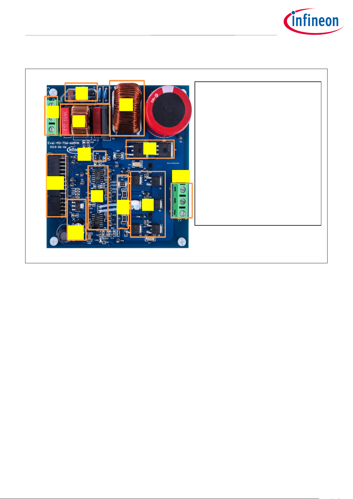
Figure 2 points out the functional groups on the top side of the EVAL-M3-TS6-665PN evaluation board.
1. J1 - AC Input connector
2. NTC and Fuse
3. EMI filter
4. PFC inductor
FC gate driver
5. P
6. PFC section with IKB20N65EH5 and
IDB15E60
7. Inverter gate drives
. C
8
urrent sensing shunt resistor RS1, RS2,
RS3
9. Inverter section with TRENCHSTOP™
IGBT
10. Auxiliary power supply
11. J3 - 30 pin iMOTION™ MADK-M3
8
interface connector for controller board
12. J4 - Motor phase connector
Figure 2 Functional groups of the EVAL-M3-TS6-665PN evaluation board’s top side
User Manual 8 <Revision 1.0>
<2019-06-05>

EVAL
-M3-TS6-665PN User Manual
iMOTION™ Modular Application Design Kit
Main features
S. No.
1
Line
AC line input
2
Neutral
AC neutral input
3
S. No.
Pin
Details
1 U Connected to motor phase U
2
3 W Connected to motor phase W
3.2 Pin assignments
General information about the connectors of the EVAL-M3-TS6-665PN evaluation board is reported. Table 3
includes the details of the AC input connector J1.
Table 3 J1- AC Line connector
Pin Details
EARTH Earth ground
able 4 provides the details of the motor side connector J4.
T
Table 4 J2- Motor side connector
V Connected to motor phase V
User Manual 9 <Revision 1.0>
<2019-06-05>

EVAL
-M3-TS6-665PN User Manual
iMOTION™ Modular Application Design Kit
Main features
Pin
Name
Pin Name Connectors
1
2
GND
Ground
3
PWMUL
3.3 V compatible logic input for low side gate driver-Phase U
4
5
PWMVH
3.3 V compatible logic input for high side gate driver-Phase V
6
+3.3V
On board 3.3 V supply
7
8
+3.3V
On board 3.3 V supply
9
PWMWH
3.3 V compatible logic input for high side gate driver-Phase W
10
11
PWMWL
3.3 V compatible logic input for low side gate driver-Phase W
12
I_U-
Negative current sense output or Ground
13
14
15
VTH
Not used
16
17
18
I_W
Not used
19
20
21
PFCG0
3.3 V compatible logic input for PFC gate driver IC
22
GND
Ground
2
24
+3.3V
On board 3.3 V supply
2
2
27
VAC+
AC voltage sensing positive cycle
28
VAC-
AC voltage sensing negative cycle
2
30
IPFC-
PFC current sensing negative
Table 5 provides the pin assignments of the 30 pins iMOTION™ MADK-M3 interface connector J3. This connector
is the interface to the controller board.
Table 5 JP1 - iMOTION™
PWMUH 3.3 V compatible logic input for high side gate driver-Phase U
GND 4 GND Ground
PWMVL 3.3 V compatible logic input for low side gate driver-Phase V
I_U Positive Current sense output
MADK-M3 30 pin interface connector for controller board
GK Gate kill signal – active low when overcurrent is detected
DCBSense DC bus positive voltage, scaled in 0-3.3 V range by a voltage divider
I_V Not used
I_V- Not used
I_W- Not used
VCC 15 V Power Supply
3 PFCG1 Not used
5 PFCGK PFC Gate kill signal – active low when PFC overcurrent is detected
6 DCBSense DC bus positive voltage, scaled in 0-3.3 V range by a voltage divider
9 IPFC+ PFC current sensing positive
User Manual 10 <Revision 1.0>
<2019-06-05>
EVAL
-M3-TS6-665PN User Manual
iMOTION™ Modular Application Design Kit
Getting Started with EVAL-M3-TS6-665PN
PC-USB
Connector
AC Power
Input
Motor Phase
Outputs
4 Getting Started with EVAL-M3-TS6-665PN
In order to run the motor system, a combination of the iMOTION™ MADK power board (EVAL-M3-TS6-665PN)
and the matching MADK control board is required. The iMOTION™ Software Tools MCEDesigner and MCEWizard
are also required in order to initialy setup the system, as well as to control and fine-tune the system
performance to match users exact needs. This chapter provides more details on setting up the system and
getting started with iMOTION™ MADK development platform.
4.1 Setting up the system
After downloading and installing the iMOTION™ PC Tools (MCEWizard and MCEDesigner), following steps needs
to be executed in order to run the motor. Refer to user manul for iMOTION™ MADK control board such as (EVALM3-102T), MCEWizard and MCEDesigner documentation for more information.
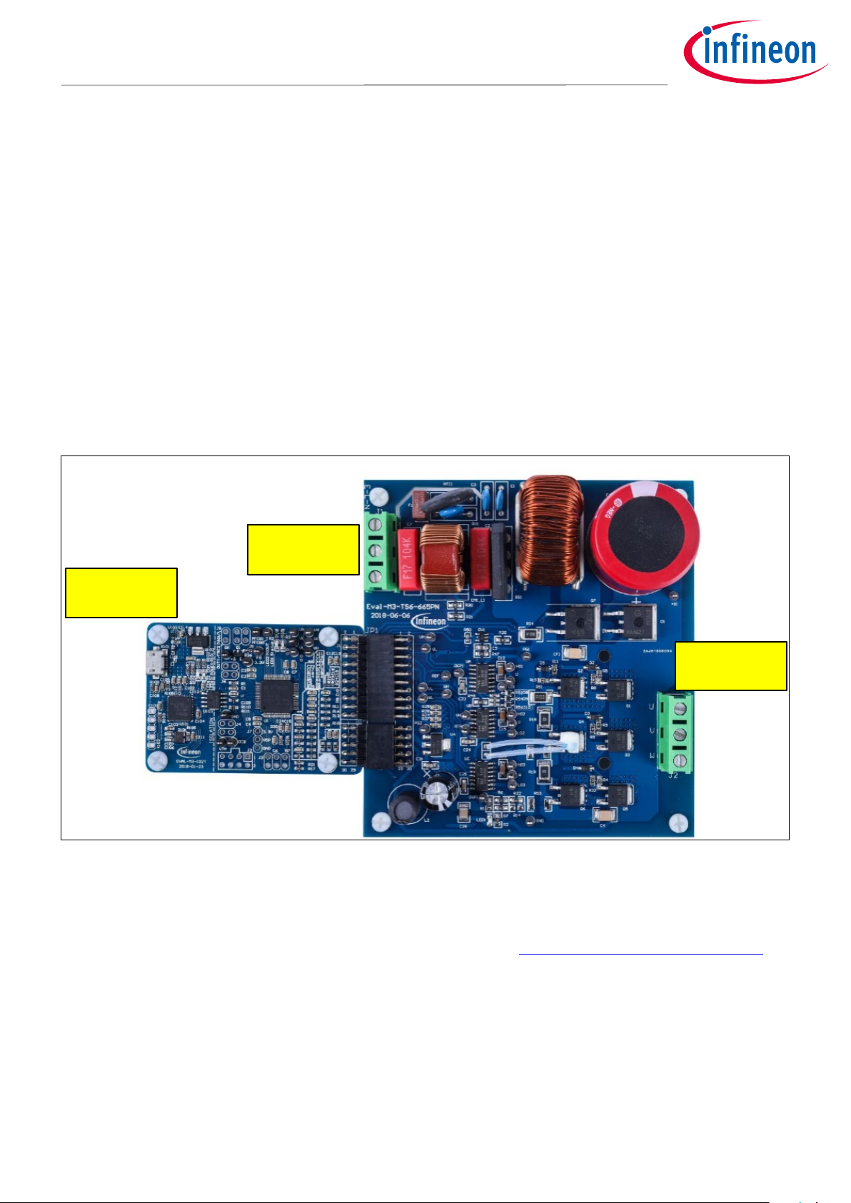
Figure 3 Shows the system connection using EVAL-M3-TS6-665PN and control board (used control board EVAL-
M3-102T for example).
Figure 3 System connection example using EVAL-M3-TS6-665PN and EVAL-M3-102T
1. Connect PC-USB connector on the on-board-debugger to the PC via USB cable.
2. Connect EVAL-M3-TS6-665PN’s MADK M3 30-pin interface connector (J3) to control board (see Figure 3).
3. Get the latest “IMC102T-F064 MCE Software Package” available on www.infineon.com/imotion-software
web page. (Infineon iMOTION™ control IC IMC102T-F064 is used for control board EVAL-M3-102T).
4. Connect motor phase outputs to the motor.
5. Use MCEWizard to enter the motor and evaluation board hardware parameters and click button “Export to
Designer file (.txt)” to system drive parameters file which will be used by MCEDesigner.
6. Connect AC power to power input connector and power on system.
7. Open MCEDesigner and open MCEDesigner default configuration file (.irc) for IMC102T devices
(IMC102T_xx.irc) by clicking “File” menu and select “Open” in the pull down list.
User Manual 11 <Revision 1.0>
<2019-06-05>

EVAL
-M3-TS6-665PN User Manual
iMOTION™ Modular Application Design Kit
Getting Started with EVAL-M3-TS6-665PN
8. Import system drive parameters file (generated in step 5) into MCEDesigner by clicking “File” > “Import
DriveParameters”. Select “Update All” radio button.
9. Program the MCE Firmware and system parameters into the internal Flash memory of iMOTION™ IC by
clicking “Tools > Programmer “in the pull down menu, and then clicking on the “Program Firmware and
Parameter” radio button. See chapter MCEDesigner setup overview setion 4.2.2 for more details. If the
latest version of MCE firmware is already programmed into the IMC102T-F064 IC, then programming
firmware can be skipped by selecting “Program Parameters” radio button option. Finally click “Start”
button to program firware and parameter (or parameters only when programming firmware was skipped).
10. Start the motor by clicking the green traffic light button in the control bar.
User Manual 12 <Revision 1.0>
<2019-06-05>
EVAL
-M3-TS6-665PN User Manual
iMOTION™ Modular Application Design Kit
Getting Started with EVAL-M3-TS6-665PN
4.2 iMOTION™ development tools and software
The iMOTION™ Development Tool installers for MCEDesigner and MCEWizard are available for download via
Infineon iMOTION
variants are listed there.
On-board debugger uses the SEGGER J-Link’s driver for UART communication with IMC102T-F064. J-Link driver
will be installed during the MCEDesigner installation. In case the driver is not installed properly, please go to
SEGGER J-Link website
Windows”.
TM
website (http://www.infineon.com/imotion-software). All the available tools and software
to download and install the latest J-Link “Software and Documentation pack for
4.2.1 MCEWizard setup overview
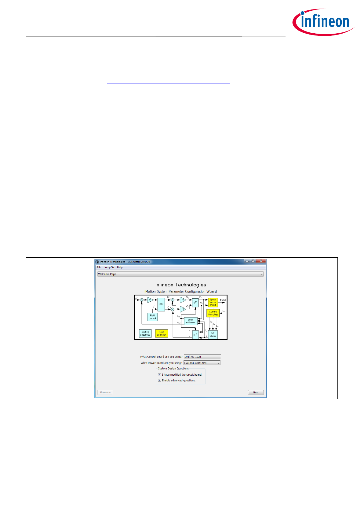
After installing the MCEWizard, the shortcut for MCEWizard appears on the Windows desktop. Double click the
shortcut to open the MCEWizard and configure the parameters for evaluation boards or motor. Figure 5 shows
the “Welcome Page” for MCEWizard, where the MADK control board or power board can be selected through
the pull-down list. Infineon keeps releasing new MADK controller and power boards. Therefore, it could happen
that some of the newest power boards are not pre-configured in the MCEWizard tool and cannot be selected
through the pull-down menu. In that case, the user should select any other power board (as similar as possible)
and follow the MCEWizard setup steps by entering the parameter values which are specific to the chosen
board. Make sure both “I have modified the circuit board” and “Enable advanced question” checkmarks are
selected. Please refer to the User Manual of the corresponding power board for additional information.
After selecting the MADK control and the power board, start the MCEWizard system setup procedure by clicking
the “Next” button in the right bottom corner as shown in Figure 4.
Figure 4 Welcome Page of MCEWizard
iMOTION™ MADK system enables users to easily test different combination of control and power board with
their motors. User should be familiar with the system level parameters which are related to the motor used.
There are very limited numbers of parameters which are specific to the control board or power board
hardware. Table 6 provides the MCEWizard setup overview for hardware related parameters. Similar tables will
be available in each power board’s User Manual. Combination of this table and the corresponding table of the
power board provides enough information to setup the MADK-based motor drive system in shortest time.
User Manual 13 <Revision 1.0>
<2019-06-05>
 Loading...