


AN2019
-03 EVAL-M1-36-44A User Manual
EVAL-M1-36-44A User Manual
iMOTION™ Modular Application Design Kit
About this document
Scope and purpose
This application note provides an overview of the evaluation board EVAL-M1-36-44A including its main features,
key data, pin assignments and mechanical dimensions.
EVAL-M1-36-44A is a complete evaluation-board including a 3-phase IPM for motor drive applications. Together
with EVAL-M1-101T or EVAL-M1-099M it features and demonstrates Infineon’s IPM technology for motor drives.
The evaluation board EVAL-M1-36-44A for Intelligent Power Modules (IPM) was developed to support customers
during their first steps designing applications with CIPOS™ Nano power modules.
Intended audience
This application note is intended for all technical specialists working with the EVAL-M1-36-44A board.
Table of Contents
About this document ....................................................................................................................... 1
Table of Contents ........................................................................................................................... 1
1 Safety precautions ......................................................................................................... 2
2 Introduction .................................................................................................................. 3
3 Main features ................................................................................................................ 5
3.1 Key data ................................................................................................................................................... 6
4 Pin Assignments ........................................................................................................... 10
5 Getting Started with EVAL-M1-36-44A ............................................................................. 12
5.1 Setting up the system............................................................................................................................ 12
5.2 iMOTION™ development tools and software ....................................................................................... 14
5.2.1 MCEWizard setup overview .............................................................................................................. 14
5.2.2 MCEDesigner setup overview .......................................................................................................... 16
6 Schematics and Layout .................................................................................................. 18
6.1 DC-Link Voltage Measurement ............................................................................................................. 18
6.2 Inverter section using CIPOS™ Nano IPM ............................................................................................. 19
6.3 Current Measurement and Over Current Circuit .................................................................................. 20
6.4 Auxiliary Power supply .......................................................................................................................... 21
6.5 PCB Layout ............................................................................................................................................ 22
7 Bill of Materials of EVAL-M1-36-44A ................................................................................. 24
8 Reference .................................................................................................................... 27
Revision History ............................................................................................................................ 28
User Manual Please read the Important Notice and Warnings at the end of this document Revision 1.0
www.infineon.com 2019-07-25

EVAL-M1-36-44A User Manual
iMOTION™ Modular Applic
ation Design Kit
Safety precautions
1
In addition to the precautions listed throughout this manual, please read and understand the following
statements regarding hazards associated with development systems.
Table 1
Safety precautions
Precautions
Caution: The ground potential of the EVAL-M1-36-44A system is biased to a negative DC
bus voltage potential. When measuring voltage waveform by oscilloscope, the scope’s
ground needs to be isolated. Failure to do so may result in personal injury or death, and
equipment damage. Darkened display LEDs are not an indication that capacitors have
discharged to safe voltage levels.
Caution: EVAL-M1-36-44A system contains DC bus capacitors which take time to
discharge after removal of the main supply. Before working on the drive system, wait
three minutes for capacitors to discharge to safe voltage levels. Failure to do so may
result in personal injury or death. Darkened display LEDs are not an indication that
capacitors have discharged to safe voltage levels.
Caution: Only personnel familiar with the drive and associated machinery should plan
or implement the installation, start-up and subsequent maintenance of the system.
Failure to comply may result in personal injury and/or equipment damage.
Caution: The surfaces of the drive may become hot, which may cause injury.
Caution: The EVAL-M1-36-44A board contains parts and assemblies sensitive to
electrostatic discharge (ESD). Electrostatic control precautions are required when
installing, testing, servicing or repairing this assembly. Component damage may result
if ESD control procedures are not followed. If you are not familiar with electrostatic
control procedures, refer to applicable ESD protection handbooks and guidelines.
Caution: An incorrectly applied or installed drive can result in component damage or
reduction in product lifetime. Wiring or application errors such as undersized motor,
incorrect or inadequate DC supply, or excessive ambient temperatures may result in
system malfunction.
Caution: Remove or connect the control board from or to the power drive. Wait three
minutes after removing power from the power drive to discharge the bus capacitors. Do
not attempt to service the drive until the bus capacitors have discharged to zero. Failure
to do so may result in personal injury or death.
Caution: The EVAL-M1-36-44A board is shipped with packing materials that need to be
removed prior to installation. Failure to remove all packing materials which are
unnecessary for system installation may result in overheating or abnormal operating
condition.
User Manual 2 Revision 1.0
2019-07-25
EVAL-M1-36-44A User Manual
iMOTION™ Modular Applic
ation Design Kit
Introduction
2
The EVAL-M1-36-44A evaluation board is a part of the iMOTION™ Modular Application Design Kit for drives
(iMOTION™ MADK).
The MADK-platform is intended to use various power stages with different control boards. These boards can be
easily interfaced through the 20 pin iMOTION™ MADK M1 interface connector which is 20 pin connector.
This evaluation board was designed to give comprehensible solutions of a power stage featuring CIPOS™ Nano.
The board is equipped with all assembly groups for sensor less field oriented control (FOC). DC-link is provided
by direct DC-input to give direct control to DC-ripple by external source. It contains in every of three output
phases emitter-shunts for current sensing and a voltage divider for DC-link voltage measurement.
The EVAL-M1-36-44A evaluation board is available from Infineon. The features of this board are described in the
design feature chapter of this document, whereas the remaining paragraphs provide information to enable the
customers to copy, modify and qualify the design for production, according to their own specific requirements.
Environmental conditions were considered in the design of the EVAL-M1-36-44A. The design was tested as
described in this document but not qualified regarding safety requirements or manufacturing and operation
over the whole operating temperature range or lifetime. The boards provided by Infineon are subject to
functional testing only.
Evaluation boards are not subject to the same procedures as regular products regarding Returned Material
Analysis (RMA), Process Change Notification (PCN) and Product Discontinuation (PD). Evaluation boards are
intended to be used under laboratory conditions by specialists only.
Introduction
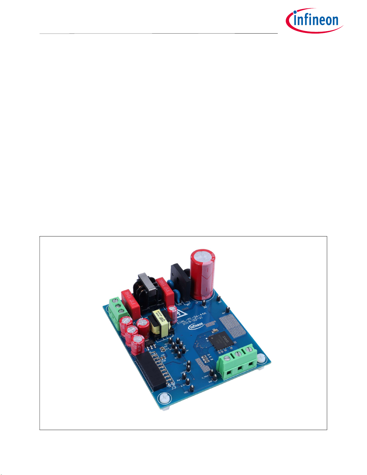
Figure 1
User Manual 3 Revision 1.0
2019-07-25
Evaluation-board EVAL-M1-36-44A

EVAL-M1-36-44A User Manual
iMOTION™ Modular Applic
ation Design Kit
Introduction
Figure 1 shows the evaluation board EVAL-M1-36-44A.This document explains the features and details of
CIPOS™ Nano IRSM836-044MA. This module is rated 250 V. Ratings and other details of the board are explained
in the subsequent sections.
User Manual 4 Revision 1.0
2019-07-25

EVAL-M1-36-44A User Manual
iMOTION™ Modular Applic
ation Design Kit
Main features
3 Main features
EVAL-M1-36-44A is an evaluation board for motor drive applications based on a 3-phase IPM. Combined with
one of the available MADK control board options, it demonstrates Infineon's IPM technology for motor drives.
The kit demonstrates Infineon’s IPM technology for motor drives.
CIPOS™ Nano Intelligent Power Module (IRSM836-044MA) features are:
Integrated gate drivers and bootstrap functionality
Open-source for leg-shunt current sensing
Protection shutdown pin
Low RDS (on) Trench MOSFET
Under-voltage lockout for all channels
Matched propagation delay for all channels
Optimized dV/dt for loss and EMI trade offs
3.3 V Schmitt-triggered active high input logic
Motor power range up to ~150 W, without heat sink
Cross-conduction prevention logic
Isolation 1500 V RMS min
ROHS compliant
The evaluation board characteristics are:
Nominal input voltage 120 V
Default 120 W motor power out
3 leg shunt configuration
3.3 V logic compatible
Overcurrent protection
Fault diagnostic output
PCB is 90x 75mm has two layers with 1oz (~35µm) copper each
RoHS compliant
AC
User Manual 5 Revision 1.0
2019-07-25
EVAL-M1-36-44A User Manual
iMOTION™ Modular Applic
ation Design Kit
Main features
3.1 Key data
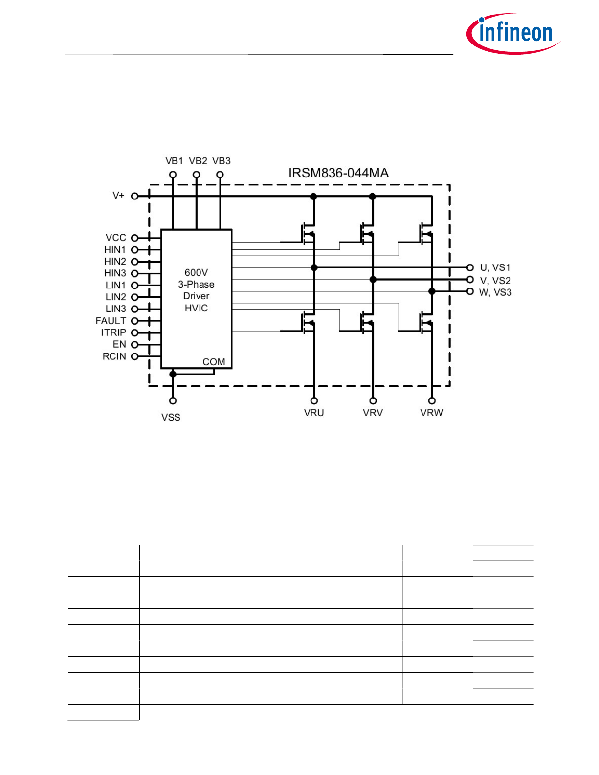
Figure 2 provides internal electrical schematics of IRSM836-044MA. For further information regarding these
IPMs like static and dynamic electrical behavior, as well as thermal and mechanical characteristics please refer
to the datasheet of the IRSM836-044MA.
Figure 2 CIPOS™ Nano internal electrical schematic
Table 2 lists major absolute maximum ratings of the IRSM836-044MA. Absolute maximum ratings are limitations
which should not be less than minimum or higher than maximum ratings. Outside these limitations for safe
operation, damage of the module should be expected.
Table 2 CIPOS™ Nano Absolute Maximum Ratings of IRSM836-044MA
Symbol Description Min Max Unit
BV
MOSFET Blocking Voltage --- 250 V
DSS
IO @ T=25°C DC Output Current per MOSFET --- 4 A
IOP
Pulsed Output Current
--- 16 A
Pd @ TC=25°C Maximum Power Dissipation per MOSFET --- 22 W
V
Isolation Voltage (1min) --- 1500 V
ISO
RMS
TJ Operating Junction Temperature -40 150 °C
TL
Lead Temperature (Soldering, 20 seconds)
--- 260 °C
TS Storage Temperature -40 150 °C
V
High Side Floating Supply Offset Voltage V
S1,2,3
V
High Side Floating Supply Voltage -0.3 250 V
B1,2,3
- 20 V
B1,2,3
+0.3 V
B1,2,3
User Manual 6 Revision 1.0
2019-07-25

EVAL-M1-36-44A User Manual
iMOTION™ Modular Applic
ation Design Kit
Main features
Input Voltage of LIN, HIN, ITRIP, EN, RCIN,
Symbol Description Min Max Unit
VCC Low Side and Logic Supply voltage -0.3 20 V
VIN
FLT
VSS -0.3 VCC+0.3 V
Table 3 depicts the recommended operating conditions of IRSM836-044MA.
Table 3 Recommended operating conditions of CIPOS™ Nano IRSM836-044MA
Symbol Description Min Max Unit
V+ Positive DC Bus Input Voltage --- 200 V
V
High Side Floating Supply Offset Voltage --- 200 V
S1,2,3
V
High Side Floating Supply Voltage VS+10 VS+20 V
B1,2,3
VCC Low Side and Logic Supply Voltage 11.5 18.5 V
VIN Input Voltage of LIN, HIN, I
, EN, FLT 0 5 V
TRIP
FP PWM Carrier Frequency --- 20 kHz
User Manual 7 Revision 1.0
2019-07-25

EVAL-M1-36-44A User Manual
iMOTION™ Modular Applic
ation Design Kit
Main features
Value
Conditions
Table 4 shows the important specifications of the evaluation board EVAL-M1-36-44A.
Table 4 EVAL-M1-36-44A board specifications
Parameters
Input
Voltage 100 - 120 V
Input current 1 A
lower AC input, less motor power output
rms
input 120 VAC, Ta=25C, IRSM836-044MA
Output
Power(3phases) 120 W** IRSM836-044MA
Current per leg 0.75 A* IRSM836-044MA
f
=6 kHz, Ta=25°C, Tc=100°C, */**without heatsink
PWM
DC Bus
Maximum DC bus voltage 200 V
Minimum DC bus voltage 60 V
Current feedback
The default configuration uses three shunts in
the emitter paths. To implement single shunt
Current sensing device
RS1,RS2,RS3
0.5 Ω
sensing, the board should be modified:
1) RS1 and RS3 have to be removed
2) IU+,IV+,IW+ have to be connected
3) R36 has to be changed to 10 kΩ
Protections
Configured by changing either shunt resistors
Output current trip level 2.5 Apk
RS1, RS2, RS3 or comparator threshold by
resistor R36
On board power supply
15V 15 V±5 %, Max 20 mA Used for CIPOS™ gate driver power
3.3V 3.3 V±5 %, Max 50 mA
Used for interface signal with control board
and alarm signals as I
, FLT/EN
TRIP
PCB characteristics
FR4, 1.6 mm thickness,
Material
2-layers. 35 µm Copper
thickness
Dimension 90 mm x 75 mm
System environment
Ambient temperature From 0 to 70°C 95 % RH max. Non-condensing
User Manual 8 Revision 1.0
2019-07-25
EVAL-M1-36-44A User Manual
iMOTION™ Modular Applic
ation Design Kit
Main features
6.
On board power supply
for
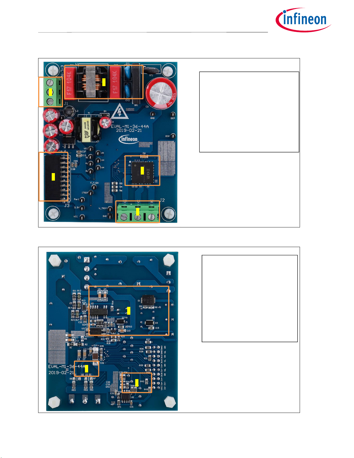
Figure 3 and Figure 4 are indicating the functional groups of the EVAL-M1-36-44A evaluation board.
4
3
Figure 3
5
1
2
Functional groups of the EVAL-M1-36-44A evaluation board’s top side
1. CIPOS™ nano module
2. Motor phase connector (J3)
3. iMOTION™ M1 20 pin
connector (J4)
4. AC input connector (J1)
5. EMI filter and Rectifier group
Figure 4
15 V and 3.3 V Generation
7. Shunt resistors
8. Over current protection
6
7
8
Functional groups of the EVAL-M1-36-44A evaluation board’s bottom side
User Manual 9 Revision 1.0
2019-07-25
 Loading...