

Infineon iMOTION EVAL-M1-101T, EVAL-M1-101T User Manual

User Manual Please read the Important Notice and Warnings at the end of this document Revision 1.6
www.infineon.com page 1 of 33 2018-11-27
AN2018-01 EVAL-M1-101T User Manual
EVAL-M1-101T User Manual
iMOTION™ Modular Application Design Kit
About this document
Scope and purpose
This application note provides an overview of the evaluation board EVAL-M1-101T including its main features,
key data, pin assignments and mechanical dimensions.
EVAL-M1-101T is an evaluation-board as part of the iMOTION™ Modular Application Design Kit. This board
features and demonstrates Infineon’s Advanced Motion Control Engine (MCE 2.0) technology for permanent
magnet motors drive over the full speed range.
The evaluation board EVAL-M1-101T was developed to support customers during their first steps designing
applications with running any permanent magnet motor via sensorless sinusoidal control.
Intended audience
This application note is intended for all technical specialists who know motor control and high power
electronics converter and this board is intended to be used under laboratory conditions.
Table of contents
About this document ....................................................................................................................... 1
Table of contents ............................................................................................................................ 1
1 Safety precautions ................................................................................................................. 3
2 Introduction .......................................................................................................................... 4
3 EVAL-M1-101T main features ................................................................................................... 5
3.1 Functional description ............................................................................................................................ 6
3.2 IMC101T-T038 pinout description .......................................................................................................... 6
3.3 EVAL-M1-101T board specifications ....................................................................................................... 8
3.4 Pin assignment ........................................................................................................................................ 9
4 Getting Started with EVAL-M1-101T......................................................................................... 11
4.1 Setting up the system............................................................................................................................ 11
4.2 iMOTION™ development tools and software ....................................................................................... 13
4.2.1 MCEWizard setup overview .............................................................................................................. 13
4.2.2 MCEDesigner setup overview .......................................................................................................... 15
5 Hardware description of EVAL-M1-101T ................................................................................... 18
5.1 Current feedback circuitry .................................................................................................................... 18
5.1.1 Shunt configuration ......................................................................................................................... 18
5.1.2 External Current feedback configuration and calculation ............................................................. 18
5.1.3 Internal Current feedback amplifier gain configuration ................................................................ 20
5.2 EVAL-M1-101T analog inputs and their MCEWizard setup ................................................................... 21
5.2.1 DC bus sensing configuration .......................................................................................................... 21
5.2.2 NTC shutdown value calculation and configuration ...................................................................... 22
5.2.3 VSP analog input control mode and PGout configuration ............................................................. 23
5.3 Schematics overview ............................................................................................................................ 26
5.4 PCB layout overview ............................................................................................................................. 27

User Manual 2 of 33 Revision 1.6
2018-11-27
EVAL-M1-101T User Manual
iMOTION™ Modular Application Design Kit
Table of contents
6 Bill of material ...................................................................................................................... 29
7 Reference ............................................................................................................................. 31
Revision history............................................................................................................................. 32
User Manual 3 of 33 Revision 1.6
2018-11-27
EVAL-M1-101T User Manual
iMOTION™ Modular Application Design Kit
Safety precautions
1 Safety precautions
In addition to the precautions listed throughout this manual, please read and understand the following
statements regarding hazards associated with development systems.
Table 1 Precautions
Attention: The ground potential of the EVAL-M1-101T system is biased to a negative DC
bus voltage potential. When measuring voltage waveform by oscilloscope, the scope’s
ground needs to be isolated. Failure to do so may result in personal injury or death and
equipment damage
Attention: Only personnel familiar with the drive and associated machinery should plan
or implement the installation, start-up and subsequent maintenance of the system.
Failure to comply may result in personal injury and/or equipment damage.
Attention: The surfaces of the drive may become hot, which may cause injury.
Attention: EVAL-M1-101T system contains parts and assemblies sensitive to Electrostatic
Discharge (ESD). Electrostatic control precautions are required when installing, testing,
servicing or repairing this assembly. Component damage may result if ESD control
procedures are not followed. If you are not familiar with electrostatic control procedures,
refer to applicable ESD protection handbooks and guidelines.
Attention: A control board, incorrectly applied or installed, can result in component
damage or reduction in product lifetime. Wiring or application errors such as under sizing
the motor, supplying an incorrect or inadequate DC supply or excessive ambient
temperatures may result in system malfunction.
Attention: Remove or connect this control board from or to the power drive. Wait three
minutes after removing power from the power drive to discharge the bus capacitors. Do
not attempt to service the drive until the bus capacitors have discharged to zero. Failure
to do so may result in personal injury or death.
Attention: EVAL-M1-101T system is shipped with packing materials that need to be
removed prior to installation. Failure to remove all packing materials which are
unnecessary for system installation may result in overheating or abnormal operating
condition.
User Manual 4 of 33 Revision 1.6
2018-11-27
EVAL-M1-101T User Manual
iMOTION™ Modular Application Design Kit
Introduction
2 Introduction
The EVAL-M1-101T evaluation board is a part of the iMOTION™ Modular Application Design Kit for drives
(iMOTION™ MADK). In order to run a motor, the mating power board is required to interface this evaluation
board.
The MADK platform is intended to use various power stages with different control boards. These boards can
easily be interfaced through the 20-pin iMOTION™ MADK M1, or the 30-pin iMOTION™ MADK M3 interface
connector. This board is equipped with 20-pin M1 connector and is intended for single motor control only.
This evaluation board is designed to give comprehensible solutions of sensorless control of permanent magnet
motors over the full speed range. It provides a capable of 3-phase and type 3 of 2-phase modulation, a microUSB connector and on board debugger isolated by digital isolator, and UART interface.
The EVAL-M1-101T evaluation board is available from Infineon. The features of this board are described in the
main features chapter of this document, whereas the remaining paragraphs provide information to enable the
customers to copy, modify and qualify the design for production according to their own specific requirements.
Environmental conditions were considered in the design of the EVAL-M1-101T, but it is not qualified regarding
safety requirements or manufacturing and operation over the whole operating temperature range or lifetime.
The boards provided by Infineon are subject to functional testing only.
Evaluation boards are not subject to the same procedures as regular products regarding Returned Material
Analysis (RMA), Process Change Notification (PCN) and Product Discontinuation (PD). Evaluation boards are
intended to be used under laboratory conditions by technical specialists only.
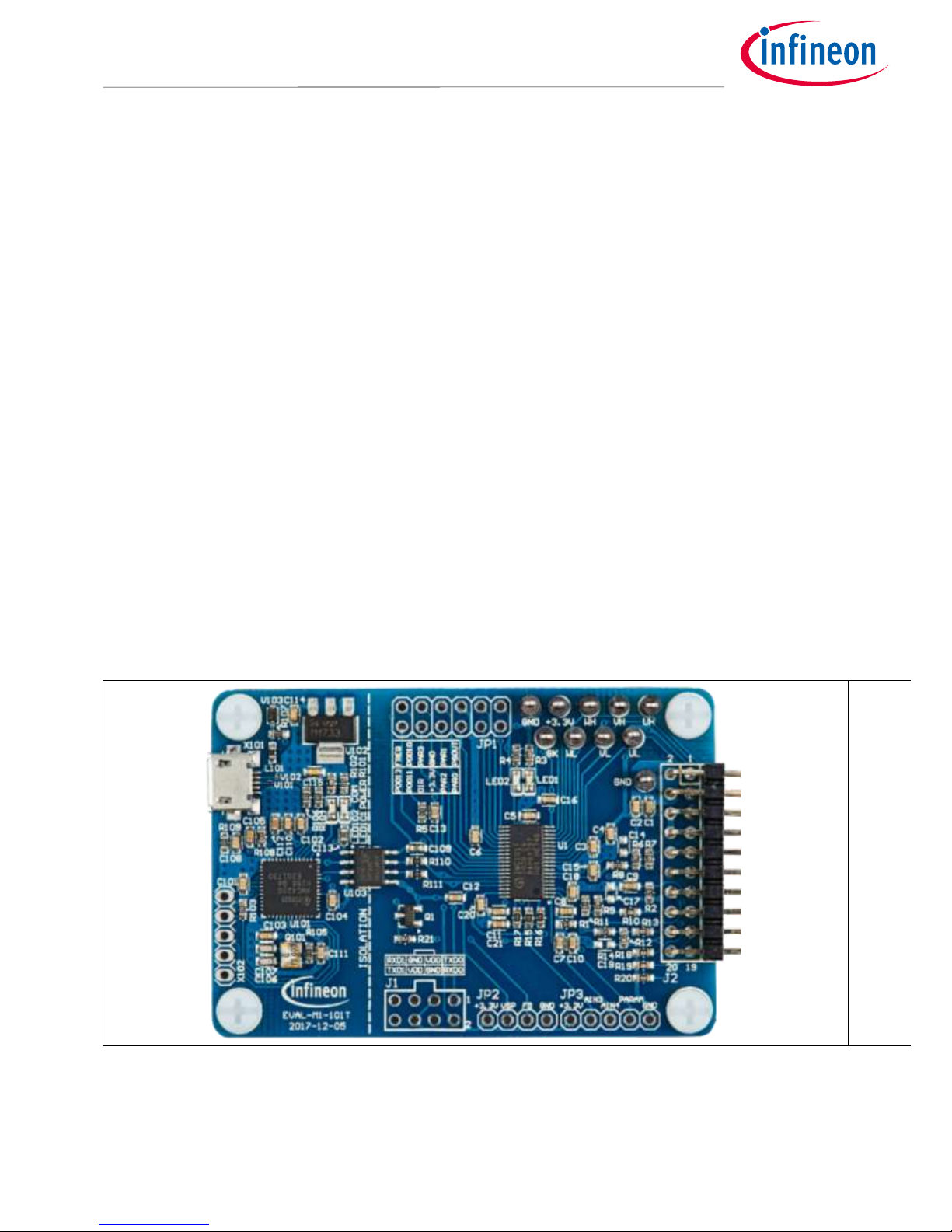
Figure 1 shows the evaluation board EVAL-M1-101T. This document explains the features and details of this board
as well as control IC which is IMC101T-T038.
Figure 1 Evaluation board EVAL-M1-101T

User Manual 5 of 33 Revision 1.6
2018-11-27
EVAL-M1-101T User Manual
iMOTION™ Modular Application Design Kit
EVAL-M1-101T main features
3 EVAL-M1-101T main features
EVAL-M1-101T is an evaluation control board for motor control applications. The kit demonstrates Infineon’s
motion control IC technology.
Main features of the IMC101T-T038 Motion Control IC are:
MCE (Motion Control Engine) as ready-to-use solution for variable speed drives
Field oriented control (FOC) for permanent magnet synchronous motor (PMSM)
Space vector PWM with sinusoidal commutation and integrated protection features
Current sensing via single or leg shunt
Sensorless operation
Various serial communication interfaces (UART, I2C, SPI)
Multiple motor parameter support
3.3V (default) or 5V VDD power supply
Flexible host interface options for speed commands: UART, I2C, SPI, PWM or analog signal
Support for IEC 60335 (‘Class B’)
Scalable package options
The evaluation board characteristics are:
Complete kit for running any permanent magnet motor via sensorless sinusoidal control
3.3V (default) or 5V VDD power supply
Micro-USB connector and on-board debugger isolated by digital isolator
Capable of 3-phase and type 3 of 2-phase modulation
RoHS complaint
PCB size is 65 x 45 mm

User Manual 6 of 33 Revision 1.6
2018-11-27
EVAL-M1-101T User Manual
iMOTION™ Modular Application Design Kit
EVAL-M1-101T main features
3.1 Functional description
Figure 2 shows a typical motor control application block diagram using the IMC101T-T038. The IMC101T-T038
provides a built-in closed loop sensorless control algorithm using the unique flexible Motion Control Engine (MCE)
for permanent magnet motors. The MCE™ consists of a collection of control elements, motion peripherals, a
dedicated motion control sequencer and internal memory to map internal signal nodes. IMC101T-T038 also
employs a unique single shunt current reconstruction circuit in addition to leg shunt current sensing circuit to
eliminate additional analog/digital circuitry.
M
3-phase
inverter
Current Sensing
single/ leg shunt
Passive
EMI Filter
& Rectifier
Host
Communication
Analog
USB
IPM based or discrete MADK power board
Gate driver
Power
supply
MADK platform connector
M1 or M3 standard
Isolated
On-Board
Debugger
EVAL-M1-101T
15V
3.3V
PWM
VDC
Figure 2 Typical Application Block Diagram Using IMC101T-T038
3.2 IMC101T-T038 pinout description
The main part of the EVAL-M1-101T MADK control board is the IMC101T-T038 iMOTION™ motor control IC.
Figure 3 depicts the pinout of the IMC101T-T038 IC. IMC101T-T038 comes in a compact 9.7mm x 6.4mm 38-pin
TSSOP package.
1
2
3
4
5
6
7
8
9
10
11
12
13
14
15
16
17
18
19
38
37
36
35
34
33
32
31
30
29
28
27
26
25
24
23
22
21
20
IMC101T
T038
(Top View)
-
VDC
IV
REFV
REFU
IU
NTC
PARAM
VSS
VDD
PWMUL
PWMUH
PWMVL
PWMVH
PWMWL
PWMWH
LED
GK
TXD1
-
IW
REFW
VSP
TXD0
RXD0
-
DUTYFREQ
-
-
DIR
PAR3
VDD
VSS
PAR2
PAR1
PAR0
PGout
RXD1
Figure 3 Pinout of IMC101T-T038

User Manual 7 of 33 Revision 1.6
2018-11-27
EVAL-M1-101T User Manual
iMOTION™ Modular Application Design Kit
EVAL-M1-101T main features
Table 2 lists the available pins of IMC101T-T038 with short descriptions. For more detailed information, please
refer to the datasheet or User Manual for iMOTION™ IMC101T-T038 motor control IC.
Table 2 IMC101T-T038 pinout description
Pin#
Type
Pin Name
Description
1 - -
not used
2
AIN
VDC
DC bus sensing input
3
AIN
IV/AIN6
Phase V current leg sensing
4
AIN
REFV/AIN7
Itrip phase V reference
5
AIN
REFU/AIN8
Itrip phase U reference
6
AIN
IU
Phase U leg sensing or single shunt
current sensing
7
AIN
NTC
external temp sense input
8
AIN
PARAM
Parameter table selection, analog
9
Power
VSS
ground
10
Power
VDD
VDD supply power
11 O PWMUL
motor PWM phase U low side
12 O PWMUH
motor PWM phase U high side
13 O PWMVL
motor PWM phase V low side
14 O PWMVH
motor PWM phase V high side
15 O PWMWL
motor PWM phase W low side
16 O PWMWH
motor PWM phase W high side
17 O LED
Status LED
18 I GK
Motor Gatekill input
19 O TXD1
UART1 Transmit for host interface
20 I RXD1
UART1 Receive for host interface
21 O PGOUT
PG output
22 I PAR0
Parameter page select bit 0
23 I PAR1
Parameter page select bit 1
24 I PAR2
Parameter page select bit 2
25
Power
VSS
ground
26
Power
VDD
VDD supply power
27 I PAR3
Parameter page select bit 3
28 I DIR
direction input
29 - -
not used
30 - -
not used
31 I DUTYFREQ
Duty/Freq input for speed input
32 - -
not used
33 I RXD0
UART0 Receive for SW download
34 O TXD0
UART0 Transmit for SW download
35
AIN
VSP
Analog speed reference input

User Manual 8 of 33 Revision 1.6
2018-11-27
EVAL-M1-101T User Manual
iMOTION™ Modular Application Design Kit
EVAL-M1-101T main features
36
AIN
REFW
Itrip phase W reference
37
AIN
IW
Phase W current leg sensing
38 - -
not used
3.3 EVAL-M1-101T board specifications
Table 3 depicts the important specifications of the evaluation board EVAL-M1-101T.
Table 3 EVAL-M1-101T board specifications
Parameters
Values
Conditions / comments
Host Interface (Not isolated)
UART(TXD RXD)
0 - VDD
Serial port 1 typical 57600 Bps
AIN
0 - VDD
analog input
DIN
0 - VDD
digital input
DOUT
0 - VDD
digital output
FG
0 - 30V
digital output with open drain
structure
Input
VDD
3.3V (default), 5V
Controller supply voltage
DC Bus
DC Bus Scaling
8.20 counts/V
13.3kΩ resistor on control board,
and 2MΩ resistor on power board
DC Bus sensing range
499.54V max
Current feedback
Internal Current Feedback
Amplifier Gain
1, 3, 6, 12
Configured by MCEWizard
Current sensing device
0 – VDD/Gain
Single shunt resistor
Leg shunt resistor
Current Op-amp Configuration
Non-Inverting
default setting
Current External Amplification
Gain
0.833
Resolution
12-bit
PCB design may reduce the
resolution
Latency
1 pwm cycle
Protections
NTC Temperature shutdown value
0 - VDD (configured by
MCEWizard)
PCB characteristics
Material
FR4, 1.6MM thickness
Copper thickness = 1oz (35um)
Dimension
65mmx45mm

User Manual 9 of 33 Revision 1.6
2018-11-27
EVAL-M1-101T User Manual
iMOTION™ Modular Application Design Kit
EVAL-M1-101T main features
Parameters
Values
Conditions / comments
System environment
Ambient temperature
-40 - 105°C
3.4 Pin assignment
Essential information about the connections of the EVAL-M1-101T evaluation board is described below.
Table 4 includes the details of UART connectors.
Table 4 J1- UART Connector
Pin Nr.
Pin
Details
1
TXD0
Serial port 0 Output, IMC101T-T038 transmit data to master controller
2
RXD0
Serial port 0 Input, IMC101T-T038 receive data from master controller
3
+3.3V
VDD power supply
4
GND
Ground
5
GND
Ground
6
+3.3V
VDD power supply
7
RXD1
Serial port 1 Input, IMC101T-T038 receive data from master controller
8
TXD1
Serial port 1 Output, IMC101T-T038 transmit data to master controller
Table 5 provides the pin assignments of the iMOTION™ MADK-M1 20 pins interface connector J2. This connector
is the interface to the power board.
Table 5 J2- iMOTION™
MADK-M1 20 pins interface connector for control board
Pin
Name
Pin Name Connectors
1
PWMUH
VDD compatible logic output for high side gate driver-Phase U
2
GND
Ground
3
PWMUL
VDD compatible logic output for low side gate driver-Phase U
4
GND
Ground
5
PWMVH
VDD compatible logic output for high side gate driver-Phase V
6
+3.3V
On board VDD supply
7
PWMVL
VDD compatible logic output for low side gate driver-Phase V
8
+3.3V
On board VDD supply
9
PWMWH
VDD compatible logic output for high side gate driver-Phase W
10
IU+
Shunt voltage phase U
11
PWMWL
VDD compatible logic output for low side gate driver-Phase W
12
IU-
Ground
13
GK
Gate kill signal – active low when over current is detected
14
DCBSENSE
DC bus positive voltage, scaled in 0 - VDD range by a voltage divider

User Manual 10 of 33 Revision 1.6
2018-11-27
EVAL-M1-101T User Manual
iMOTION™ Modular Application Design Kit
EVAL-M1-101T main features
Pin
Name
Pin Name Connectors
15
VTH
Thermistor input
16
IV+
Shunt voltage phase V
17
IV-
Ground
18
IW+
Shunt voltage phase W
19
IW-
Ground
20
VCC
Defined for 15 V Power Supply (not used in this board)
Table 6, Table 7 and Table 8 include the details of test signal pin connectors.
Table 6 Digital signal test pin connecter JP1
Pin
Name
Pin Name Connectors
1
PGOUT
PG (Pulse Generation) output
2
PAR0
Parameter page select bit 0
3
PAR1
Parameter page select bit 1
4
PAR2
Parameter page select bit 2
5
GND
Ground
6
+3.3V
VDD power supply
7
PAR3
Parameter page select bit 3
8
DIR
Direction input
9 - not used
10 - not used
11
DUTYFREQ
Duty/Frequency input for speed input
12 - not used
Table 7 VSP signal test pin connector JP2
Pin
Name
Pin Name Connector
1
+3.3V
VDD power supply/ +3.3V by default
2
VSP
Analog speed reference input
3
FG
open drain output for speed as shown in Figure 23
4
GND
Ground
Table 8 Analog signal test pin connector JP3
Pin
Name
Pin Name Connector
1
+3.3V
VDD power supply
2 - not used
3 - not used
4
PARAM
Parameter table selection
5
GND
Ground
 Loading...