

Infineon BCR420U, BCR421U Schematic [ru]
LED Driver
Features
BCR420U / BCR421U
• Continuous output current up to 150mA
with external resistor
• Suitable for supply voltages of 40V and above
• Low side current control, µC compatible
PWM input (BCR421U) up to 10kHz
• Up to 1W power dissipation in a small SC74 package
• Negative thermal coefficient reduces output current
at higher temperatures
• Easy paralleling of drivers to increase current
• Pb-free (RoHS compliant) package
• Automotive qualified according AEC Q101
Applications
• Architectural LED lighting
• Channel letters for advertising, LED strips for decorative lighting
• Retail lighting in fridge, freezer case and vending machines
4
5
6
3
2
1
• Emergency lighting (e.g. steps lighting, exit way signs etc.)
• Ship, train and aircraft interior illumination
General Description
The BCR420U/BCR421U provide a low-cost solution for driving 0.25W LEDs with a typical
LED current ILED of 75mA to 150mA. Internal breakdown voltage is >40V, this is the
maximum voltage that the LED driver IC can sustain when connected to it directly.
The BCR420U/BCR421U can be operated at supply voltages of 40V or higher, by simply
stacking a series of LEDs in front of the LED drivers, resulting in a certain voltage drop
depending on the forward voltages of the LEDs, reducing the voltage at the supply pin
of the driver below 40V. A digital input pin (BCR421U) allows dimming via a Microcontroller
with frequencies of up to 10 kHz. A reduction of the output current at higher temperatures
is the result of the negative thermal coefficient of 0.2% /K. of the LED drivers.
With no need for additional external components like inductors, capacitors and
free wheeling diodes, the BCR420U/BCR421U LED drivers are a cost-efficient and
PCB-area saving solution for driving 0.25W LEDs.
1
2010-01-15
6 5 4
1 2 3
BCR420U / BCR421U
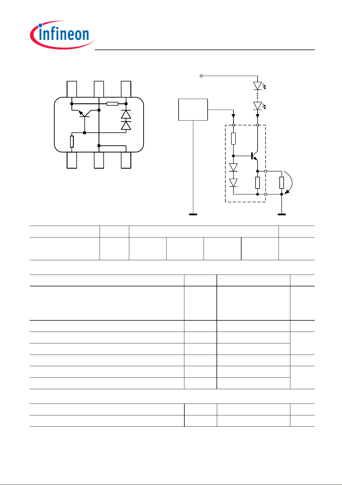
Typical ApplicationPin Configuration
+Vs
µC
I
EN IOUT
1
EN
OUT
2,3,5
Rext
6
Vdrop
GND
4
BCR421U
Type Marking Pin Configuration Package
BCR420U
BCR421U
40
41
1 = EN 2;3;5 =
OUT
4 = GND 6 = R
ext
SC74
SC74
Maximum Ratings
Parameter
Enable voltage
BCR420U
BCR421U
Output current
Output voltage
Reverse voltage between all terminals
Total power dissipation,
T
= 100 °C
S
Junction temperature
Symbol Value Unit
V
EN
V
40
4.5
I
V
V
P
T
out
out
R
tot
j
200 mA
38 V
0.5
1000 mW
150 °C
Storage temperature
Thermal Resistance
Parameter
Junction - soldering point
1
For calculation of
R
please refer to Application Note Thermal Resistance
thJA
1)
T
stg
-65 ... 150
Symbol Value Unit
R
thJS
2
50
2010-01-15
K/W

BCR420U / BCR421U
Electrical Characteristics at
T
=25°C, unless otherwise specified
A
Parameter
Characteristics
Collector-emitter breakdown voltage
I
= 1 mA,
C
I
B
= 0
Enable current
V
= 24 V , BCR420U
EN
V
= 3.3 V , BCR421U
EN
DC current gain
I
= 50 mA,
C
V
CE
= 1 V
Internal resistor
I
= 10 mA
Rint
Bias resistor
BCR420U
Symbol Values Unit
min. typ. max.
V
BR(CEO)
I
EN
h
FE
R
int
R
B
40 - - V
-
-
1.2
1.2
-
-
200 350 500 -
65 90 105 Ω
-
20
-
mA
kΩ
BCR421U
Output current
V
V
V
out
out
out
= 1.4 V,
= 1.4 V,
> 2.0 V,
V
= 24 V, BCR420U
EN
V
= 3.3 V, BCR421U
EN
V
= 24 V,
EN
R
EXT
= 5.1 Ω,
BCR420U
V
> 2.0 V,
out
V
EN
= 3.3 V,
R
EXT
= 5.1 Ω,
BCR421U
Voltage drop (
I
= 10mA
out
V
-
V
S
)
E
DC Characteristics with stabilized LED load
Lowest sufficient supply voltage overhead
I
> 18mA
out
Output current change versus
V
= 24 V;
EN
V
> 2.0 V, BCR420U
out
T
A
I
out
V
drop
V
Smin
∆
I
out/Iout
-
8
8
-
-
1.5
10
10
150
150
-
12
12
-
-
mA
0.85 0.95 1.05 V
- 1.4 - V
-
-0.2
%/K
-
V
= 3.3 V;
EN
V
> 2.0 V, BCR421U
out
Output current change versus
V
V
EN
EN
= 24 V;
= 3.3 V;
V
> 2.0 V, BCR420U
out
V
> 2.0 V, BCR421U
out
V
-
S
∆
I
out/Iout
-
-
3
-0.2
1
1
%/V
-
-
2010-01-15
BCR420U / BCR421U
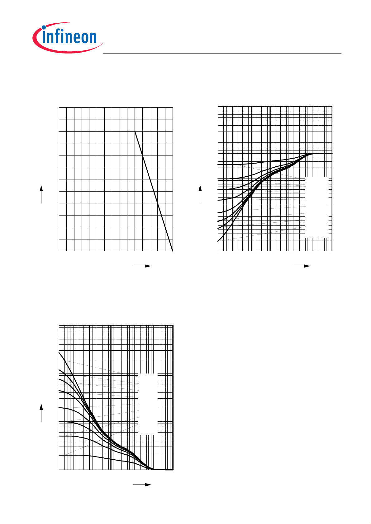
Total power dissipation
1200
mW
1000
900
800
tot
P
700
600
500
400
300
200
100
0
0 20 40 60 80 100 120
P
tot
= f (
T
)
S
Permissible Pulse Load
R
thJS
= f (
t
)
p
3
10
2
10
thJS
R
1
°C
T
10
0
10
-1
10
150
S
10
-6
10
-5
10
-4
10
-3
10
-2
D = 0,5
0,2
0,1
0,05
0,02
0,01
0,005
0
s
T
0
10
P
Permissible Pulse Load
P
totmax
/
P
totDC
= f (
t
)
p
3
10
-
totDC
P
/
2
10
totmax
P
1
10
0
10
10
-6
10
-5
10
-4
10
D = 0
0.005
0.01
0.02
0.05
0.1
0.2
0.5
-3
10
-2
s
T
0
10
P
4
2010-01-15
 Loading...