

Inficon BM1000 Series, BM1000 PROFIBUS, BM1000 PROFINET, BM1000 DeviceNet, BM1000 EtherNet/IP Operating Instructions Manual
...Page 1

Translation of the Original Operating Instructions
BM1000
Bus-Modul
Catalog No.
560-315 (Profibus), 560-316 (Profinet), 560-317 (DeviceNet), 560-318 (Ethernet/IP)
From software version
- -
jiqb10en1-06-(1901)
Page 2

INFICON GmbH
Bonner Strasse 498
50968 Cologne, Germany
Page 3

INFICON Table of Contents
Table of Contents
1 About these instructions ...................................................................................................................................4
1.1 Other associated documents ....................................................................................................................4
1.2 Target groups ...........................................................................................................................................4
2 Safety ...............................................................................................................................................................5
2.1 Owner requirements .................................................................................................................................5
2.2 Operator requirements..............................................................................................................................5
2.3 Warnings...................................................................................................................................................5
3 Shipment, Transport, Storage ..........................................................................................................................7
4 Description........................................................................................................................................................8
4.1 Construction of the bus module ................................................................................................................8
4.2 Function ....................................................................................................................................................8
4.3 Technical data ..........................................................................................................................................9
5 Installation and removal..................................................................................................................................10
5.1 Mount the bus module and the DIN-TS35 top hat rail ............................................................................10
5.2 Establish connections .............................................................................................................................10
5.3 Remove the bus module from the DIN-TS35 top hat rail........................................................................11
6 Decommissioning the measuring instrument..................................................................................................12
6.1 Disposing of the device...........................................................................................................................12
6.2 Sending in the device .............................................................................................................................12
7 Appendix.........................................................................................................................................................14
7.1 CE Declaration of Conformity .................................................................................................................14
7.2 RoHS ......................................................................................................................................................15
BM1000-Operating-Instructions-jiqb10en1-06-(1901) iii
Page 4

1 | About these instructions INFICON
1 About these instructions
1.1 Other associated documents
• Operating instructions of the connected leak detector
• Protocol Descriptions, Document No. jira54
1.2 Target groups
This instruction manual is aimed at the operator of the device and at technically
qualified specialists, with experience in the field of leak testing technology.
4 / 20 BM1000-Operating-Instructions-jiqb10en1-06-(1901)
Page 5

INFICON Safety | 2
2 Safety
2.1 Owner requirements
Safety conscious
operation
Personnel
qualifications
Operate and install the device only in technically perfect working order and as
specified, in a safety-conscious and hazard-conscious manner and in compliance with
these instructions.
► Fulfill and ensure compliance with the following regulations:
- Intended use
Universally valid safety and accident prevention regulations
- International, national and local standards and guidelines
- Additional device-related provisions and regulations
► Use only original parts or parts approved by the manufacturer.
► Keep this manual available at the operating site.
► All work must be performed only by technically qualified specialists who have been
trained on the device.
► Allow personnel in training to work on the device only under the supervision of
technically qualified specialists.
► Make sure that the authorized personnel have read and understood these
instructions and all other applicable documents (refer to "Other associated
documents"), especially the information on safety, maintenance and repairs, before
starting work.
► Define responsibilities, authorizations and supervision of personnel.
2.2 Operator requirements
► Read, observe and follow the information in these instructions and the working
instructions created by the owner, especially the safety instructions and warnings.
2.3 Warnings
DANGER
Imminent hazard resulting in death or serious injuries
BM1000-Operating-Instructions-jiqb10en1-06-(1901) 5 / 20
Page 6
2 | Safety INFICON
WARNING
Hazardous situation resulting in potential death or serious injuries
CAUTION
Hazardous situation resulting in minor injuries
NOTICE
Hazardous situation resulting in damage to property or the environment
6 / 20 BM1000-Operating-Instructions-jiqb10en1-06-(1901)
Page 7

INFICON Shipment, Transport, Storage | 3
3 Shipment, Transport, Storage
Scope of delivery
Transport
Storage
Item Quantity
Bus module 1
Operating instructions 1
► Please check the scope of delivery of the product for completeness after receipt.
NOTICE
Damage due to unsuitable packaging material
Transport in unsuitable packaging material can damage the device.
Transport the device only in the original packaging.
Keep the original packaging.
► Store the device taking into consideration the technical data, refer to Chapter 4.3,
page 9.
BM1000-Operating-Instructions-jiqb10en1-06-(1901) 7 / 20
Page 8

4 | Description INFICON
4 Description
4.1 Construction of the bus module
Fig.1:
Front view
1 Connection for the cable to the
leak detector (LD)
4.2 Function
The bus module is a device interface between e.g. the MSB box of the mass
spectrometer module LDS3000 and an external controller. The bus module BM1000 is
available from INFICON in the following versions:
• 560-315 BM1000 PROFIBUS
• 560-316 BM1000 PROFINET
• 560-317 BM1000 DeviceNet
• 560-318 BM1000 EtherNet/IP
2 Status LED Lights up green when
the operating voltage is applied to
the bus module.
8 / 20 BM1000-Operating-Instructions-jiqb10en1-06-(1901)
Page 9

INFICON Description | 4
4.3 Technical data
Dimensions (L×W×H) 107.6 mm x 89.7 mm x 76.6 mm
Weight 0.5 kg (1.74 lb.)
Table1:
Protection class IP20
Nominal voltage 24 V
Nominal frequency DC voltage
Nominal power <3 VA
Table2:
Max. height above sea level 2000 m
Max. relative humidity above 40 °C 50%
Max. relative humidity from 31 °C to 40°C80% to 50% (decreasing linearly)
Max. humidity up to 31 °C 80%
Mechanical data
Electrical data
Max. storage temperature -20 °C … 60 °C
Permissible ambient temperature (during
operation)
Pollution degree II
Table3:
Ambient conditions
5 °C … 50 °C
BM1000-Operating-Instructions-jiqb10en1-06-(1901) 9 / 20
Page 10

5 | Installation and removal INFICON
5 Installation and removal
NOTICE
Install the bus module so that you can always easily disconnect the cable to the leak
detector.
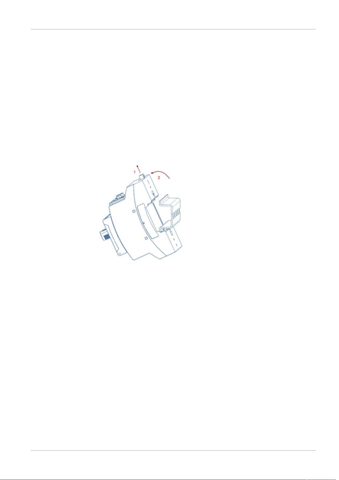
5.1 Mount the bus module and the DIN-TS35 top
hat rail
Fig.2:
Mounting of bus module
1. Hook device on top hat rail at bottom.
2. Press device onto top hat rail at top.
5.2 Establish connections
Connect the bus module with the leak detector
The bus module communicates via data cable with the leak detector and is supplied
with voltage by the data cable.
ü The device must be supplied with a circuit that meets the requirements of "Energy-
limited circuits" of DIN EN 61010-1 (VDE 0411-1).
ü INFICON data cable
1
Connect the bus module (connection LD) via the data cable with the leak
detector.
10 / 20 BM1000-Operating-Instructions-jiqb10en1-06-(1901)
Page 11
INFICON Installation and removal | 5
2
Connect the bus module with the external controller by means of the built-in field
bus module.
The bus module is activated in the leak detector, e.g. the MSB box of the LDS3000,
see the leak detector manual.
Communication with field bus master
For information on establishing communication with the Field bus master, see
Interface protocols, jira54 and kirb43.
5.3 Remove the bus module from the DIN-TS35 top
hat rail
Fig.3:
Removing the bus module
1. Use the flat-tip screwdriver to pull out the locking device.
2. Pull the device off of the top hat rail.
BM1000-Operating-Instructions-jiqb10en1-06-(1901) 11 / 20
Page 12

6 | Decommissioning the measuring instrument INFICON
6 Decommissioning the measuring
instrument
6.1 Disposing of the device
The device can either be disposed of by the operator or be sent to the manufacturer.
The device consists of materials that can be recycled. This option should be exercised
to prevent waste and also to protect the environment.
During disposal, observe the environmental and safety regulations of your country.
6.2 Sending in the device
WARNING
Danger due to harmful substances
Contaminated devices could endanger the health. The contamination declaration
serves to protect all persons who come into contact with the device.
► Fill in the declaration of contamination completely.
1
Please do not hesitate to contact us and send a completed declaration of
contamination before sending anything to us.
ð You will then receive a return number from us.
2
Use the original packaging when returning.
3
Before sending the device, attach a copy of the completed contamination
declaration. See below.
12 / 20 BM1000-Operating-Instructions-jiqb10en1-06-(1901)
Page 13

INFICON Decommissioning the measuring instrument | 6
BM1000-Operating-Instructions-jiqb10en1-06-(1901) 13 / 20
Page 14
7 | Appendix INFICON
7 Appendix
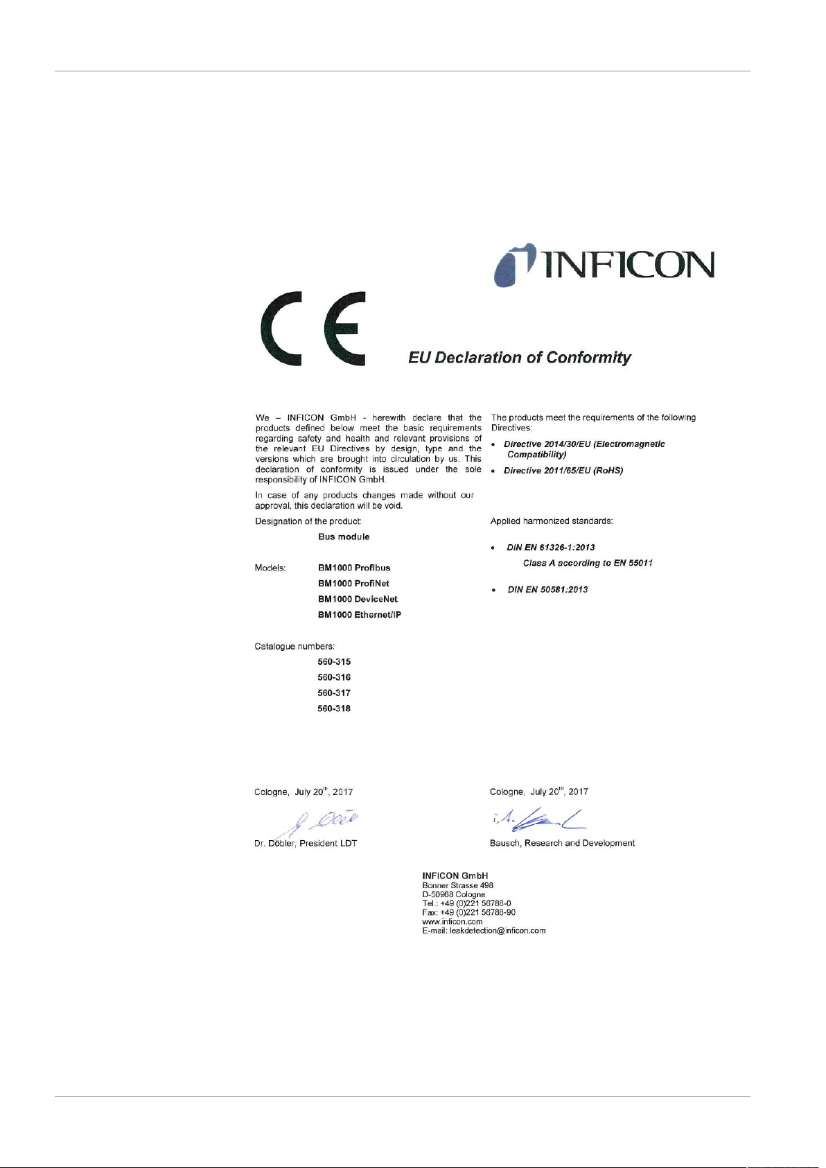
7.1 CE Declaration of Conformity
14 / 20 BM1000-Operating-Instructions-jiqb10en1-06-(1901)
Page 15

INFICON Appendix | 7
7.2 RoHS
BM1000-Operating-Instructions-jiqb10en1-06-(1901) 15 / 20
Page 16

7 | Appendix INFICON
16 / 20 BM1000-Operating-Instructions-jiqb10en1-06-(1901)
Page 17

INFICON Appendix | 7
BM1000-Operating-Instructions-jiqb10en1-06-(1901) 17 / 20
Page 18

7 | Appendix INFICON
18 / 20 BM1000-Operating-Instructions-jiqb10en1-06-(1901)
Page 19

Page 20

 Loading...