

Page 1
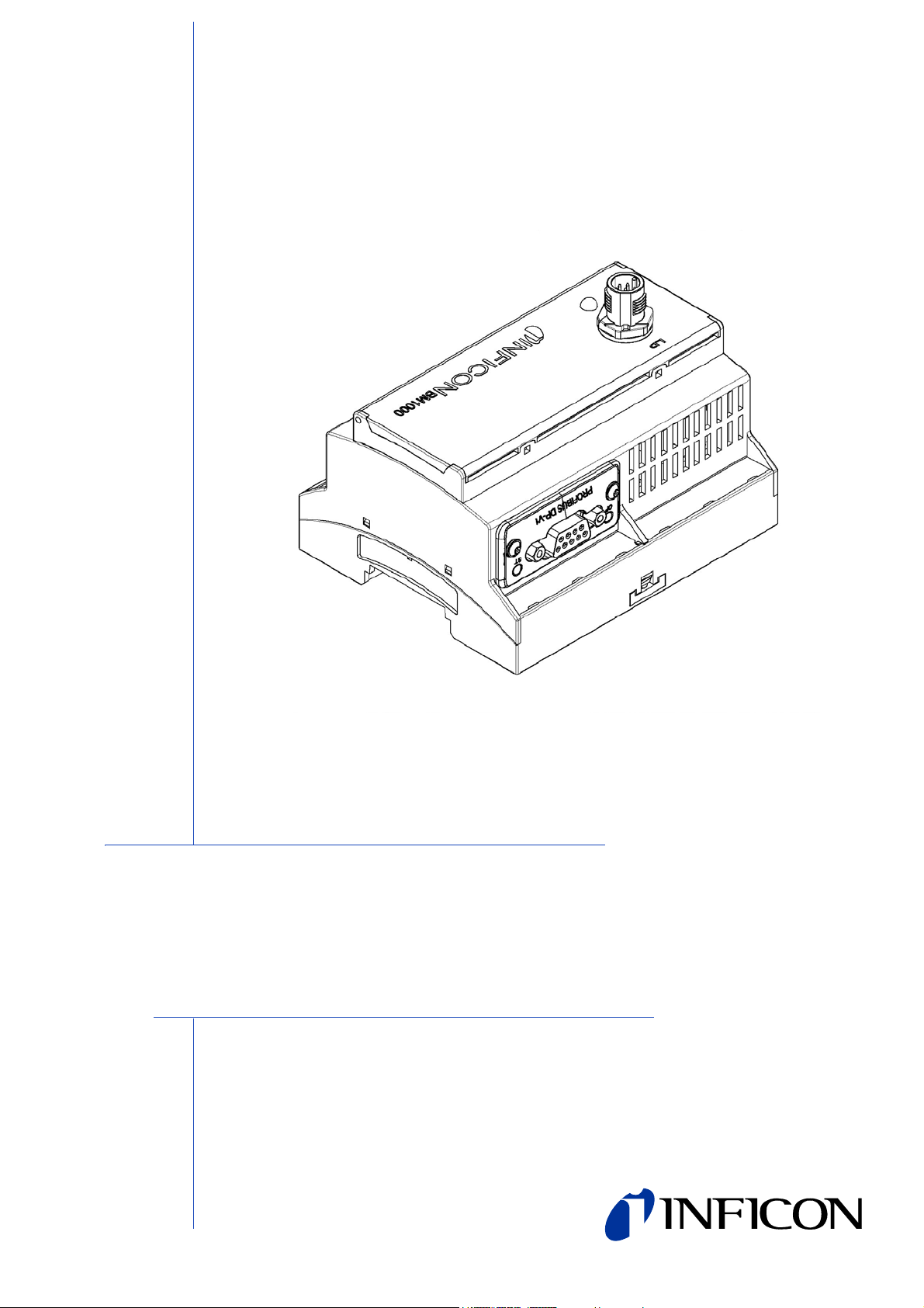
INSTALLATION MANUAL
Type designation
BM1000
Product description
Bus module
Catalog no.
Document no.
560-315
jiqb10e1-b (1301)
Page 2

Reprint, translation and duplication need to be approved in writing by
INFICON GmbH.
2
Page 3

Content
1 About this manual . . . . . . . . . . . . . . . . . . . . . . . . . . . . . . 4
1.1 Target groups . . . . . . . . . . . . . . . . . . . . . . . . . . . . . . . . . . . . . . . . . . . . 4
1.2 Other applicable documents . . . . . . . . . . . . . . . . . . . . . . . . . . . . . . . . . 4
1.3 Presentation of information . . . . . . . . . . . . . . . . . . . . . . . . . . . . . . . . . . 4
1.3.1 Warnings . . . . . . . . . . . . . . . . . . . . . . . . . . . . . . . . . . . . . . . . . 4
1.3.2 Text markings . . . . . . . . . . . . . . . . . . . . . . . . . . . . . . . . . . . . . 5
2 Safety . . . . . . . . . . . . . . . . . . . . . . . . . . . . . . . . . . . . . . . . . 6
2.1 Intended use . . . . . . . . . . . . . . . . . . . . . . . . . . . . . . . . . . . . . . . . . . . . . 6
2.2 User requirements . . . . . . . . . . . . . . . . . . . . . . . . . . . . . . . . . . . . . . . . 6
2.3 User requirements . . . . . . . . . . . . . . . . . . . . . . . . . . . . . . . . . . . . . . . . 6
3 Shipment, transport, storage . . . . . . . . . . . . . . . . . . . . . 7
3.1 Checking shipment . . . . . . . . . . . . . . . . . . . . . . . . . . . . . . . . . . . . . . . . 7
3.2 Transport . . . . . . . . . . . . . . . . . . . . . . . . . . . . . . . . . . . . . . . . . . . . . . . 7
3.3 Storage . . . . . . . . . . . . . . . . . . . . . . . . . . . . . . . . . . . . . . . . . . . . . . . . . 7
4 Description . . . . . . . . . . . . . . . . . . . . . . . . . . . . . . . . . . . . 8
4.1 Design of the bus module . . . . . . . . . . . . . . . . . . . . . . . . . . . . . . . . . . . 8
4.2 Function . . . . . . . . . . . . . . . . . . . . . . . . . . . . . . . . . . . . . . . . . . . . . . . . 8
4.3 Technical data . . . . . . . . . . . . . . . . . . . . . . . . . . . . . . . . . . . . . . . . . . . 9
4.3.1 Mechanical data . . . . . . . . . . . . . . . . . . . . . . . . . . . . . . . . . . . 9
4.3.2 Electrical data . . . . . . . . . . . . . . . . . . . . . . . . . . . . . . . . . . . . . 9
4.3.3 Ambient conditions . . . . . . . . . . . . . . . . . . . . . . . . . . . . . . . . . 9
5 Installation and removal . . . . . . . . . . . . . . . . . . . . . . . . 10
5.1 Installation of the bus module . . . . . . . . . . . . . . . . . . . . . . . . . . . . . . . 10
5.1.1 Establish connections . . . . . . . . . . . . . . . . . . . . . . . . . . . . . . 10
5.2 Removal of the bus module . . . . . . . . . . . . . . . . . . . . . . . . . . . . . . . . 11
6 Disposal . . . . . . . . . . . . . . . . . . . . . . . . . . . . . . . . . . . . . 12
Content 3
Page 4
1 About this manual
1.1 Target groups
This installation manual is intended for the operator and for technically qualified
personnel with experience in leak detection technology and integration of leak
detection devices in leak detection systems. In addition, the installation and use of
the unit require knowledge of electronic interfaces.
1.2 Other applicable documents
Installation manual for mass spectrometer module jiqa54
Interface protocols jira54
1.3 Presentation of information
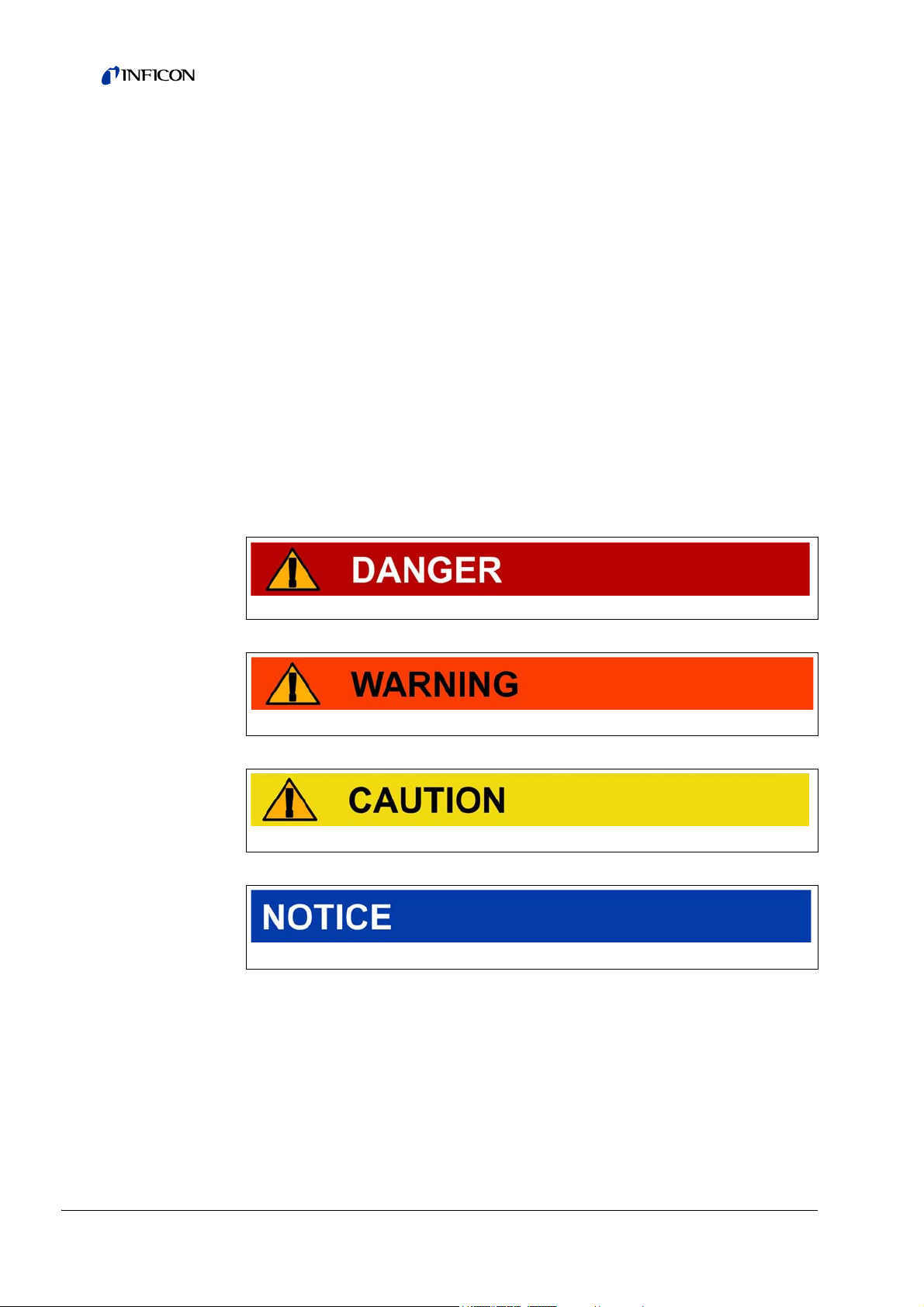
1.3.1 Warnings
Imminent threat of danger resulting in deat h or se ve re in jurie s
Dangerous situation potentially resulting in death or severe injuries
Dangerous situation resulting in minor injuries
Dangerous situation resulting in damage to property or the environment
4 About this manual
Page 5

1.3.2 Text markings
Marking Meaning
►
1, 2, 3, ... Several instructions in a fixed order
S
MALL CAPS
Information
Requirement for execution of an action
Tool or aid for an action
Instruction
Result of an action
Designation of the unit or command/term from the menu
Useful tips and information
About this manual 5
Page 6

2Safety
2.1 Intended use
The bus module is a device interface between the MSB box of the mass
spectrometer module LDS3000 and an external controller, for example.
► Install, operate and service the unit only in compliance with this manual.
► Comply with the limits of application (see Chapter 4.2, page 8).
2.2 User requirements
Safety conscious operation
► Operate and install the unit only if it is in perfect working order and as intended,
in a safety-conscious manner and fully aware of dangers, in compliance with this
manual.
► Fulfill and ensure compliance with the following regulations:
– Intended use
– Generally applicable safety and accident prevention regulations
– International, national and local standards and guidelines
– Additional provisions and regulations that are specific to the unit
► Use only original parts or parts approved by the manufacturer.
► Keep this manual available at the operating site.
Personnel qualifications
► All work must be performed only by technical specialists who have been trained
on the unit.
► Allow personnel in training to work with the unit only under the supervision of
technical specialists.
► Make sure that the authorized personnel have read and understood this manual
and all other applicable documents (see Chapter 1.2, page 4), especially the
information on safety, maintenance and repairs, before starting work.
► Define responsibilities, authorizations and supervision of personnel.
2.3 User requirements
► Read, observe and follow the information in this manual and the working
instructions created by the owner, especially the safety instructions and warnings.
► Perform all work based on the complete manual.
6 Safety
Page 7

3 Shipment, transport, storage
3.1 Checking shipment
Scope of delivery
Article Quantity
Bus module 1
Installation manual 1
► Check shipment to make sure it is complete.
3.2 Transport
Damage due to unsuitable packaging material
Transport in unsuitable packaging material can damage the unit.
► Transport the unit only in the original packaging material.
► Keep original packaging material.
3.3 Storage
► Always store the unit in compliance with the technical data, see Chapter 4.3,
page 9.
Shipment, transport, storage 7
Page 8

4 Description
4.1 Design of the bus module
Fig: 1 Front view
1- LD
Connection for the cable to the mass spectrometer module
4.2 Function
2- Status LED
Color Status Meaning
Green Continuously on Operating voltage present
The bus module is a device interface between the MSB box of the mass
spectrometer module LDS3000 and an external controller, for example. The bus
module is equipped with
• a PROFIBUS module
► information on the PROFIBUS module: see file ABCC_DPV1_1_32.pdf on
included USB flash drive.
Bus modules with other built-in Fieldbus modules are available on request (e.g.
CANopen, Modbus-RTU, Modbus-TCP, DeviceNet, CC-Link, EtherNet/IP, ProfinetIO, EtherCAT).
8 Description
Page 9

4.3 Technical data
4.3.1 Mechanical data
Dimensions (W x H x D) 107.6 mm x 89.7 mm x 76.6 mm
Weight 500 g
4.3.2 Electrical data
Supply voltage 24 V DC
4.3.3 Ambient conditions
Permissible ambient temperature
(during operation)
Permissible storage temperature -20 °C ... 60 °C
< +31 °C 80%
Max. relative
humidity
Type of protection IP 20
Pollution degree II
Max. altitude above sea level 2000 m
+31 °C to +40 °C decreasing linearly from 80% ... 50%
> +40 °C 50%
10 °C ... 45 °C
Description 9
Page 10

5 Installation and removal
5.1 Installation of the bus module
Fig: 2 Mount bus module on DIN-TS35 top hat rail
DIN-TS35 top hat rail
1 Hook unit on top hat rail at bottom.
2 Press unit onto top hat rail at top.
5.1.1 Establish connections
Connection of bus module with MSB box
The bus module communicates via a data cable with the mass spectrometer module
and is supplied with voltage by means of the data cable.
Data cables from INFICON
1 Connect bus module (connection L
(connection I/O).
Information If you disconnect the data cable from the connection L
2 Connect the bus module with the external controller by means of the built-in
Fieldbus module.
D) via data cable with MSB box
D of the bus
module during operation, the communication between the bus module
and the MS module will be interrupted.
Communication with Fieldbus master
► For information on establishing communication with the Fieldbus master, see
Interface protocols, jira54.
10 Installation and removal
Page 11

5.2 Removal of the bus module
Fig: 3 Removal of the bus module
Flat-tip screwdriver
1 Use the flat-tip screwdriver to pull out the locking device.
2 Pull the bus module off of the top hat rail.
Installation and removal 11
Page 12

6 Disposal
The unit can be disposed of by the user.
Information The unit is made of materials that can be reused. By recycling these
materials you reduce waste and environmental impact.
► For disposal, always comply with local and regional environmental and safety
regulations.
12 Disposal
Page 13

Disposal 13
Page 14

INFICON GmbH, Bonner Strasse 498, D-50968 Cologne, Germany
UNITED STATES TAIWAN JAPAN KOREA SINGAPORE GERMANY FRANCE UNITED KINGDOM HONG KONG
Visit our website for contact information and other sales offices worldwide. www.inficon.com
Document: jiqb10e1-b (1301)
 Loading...