

Page 1
Communication Protocol
Profibus
DP/V1 Interface for Bayard-Alpert Pirani Capacitance Diaphragm Gauge
BCG450-SP
tira41e1 (2005-06) 1
Page 2
About this Document
This document describes the functionality and programming of the Profibus interface of the BCG450-SP gauge.
For safety information on and technical data of the gauges, please refer
to the respective operating manuals (→ [1], [3]).
In information referring to the ionization vacuum measuring part of the gauge, the
short designation "BA" (Bayard-Alpert measuring principle) is used.
The designation "Pirani" is used in information referring to the Pirani vacuum
measuring part of the gauge.
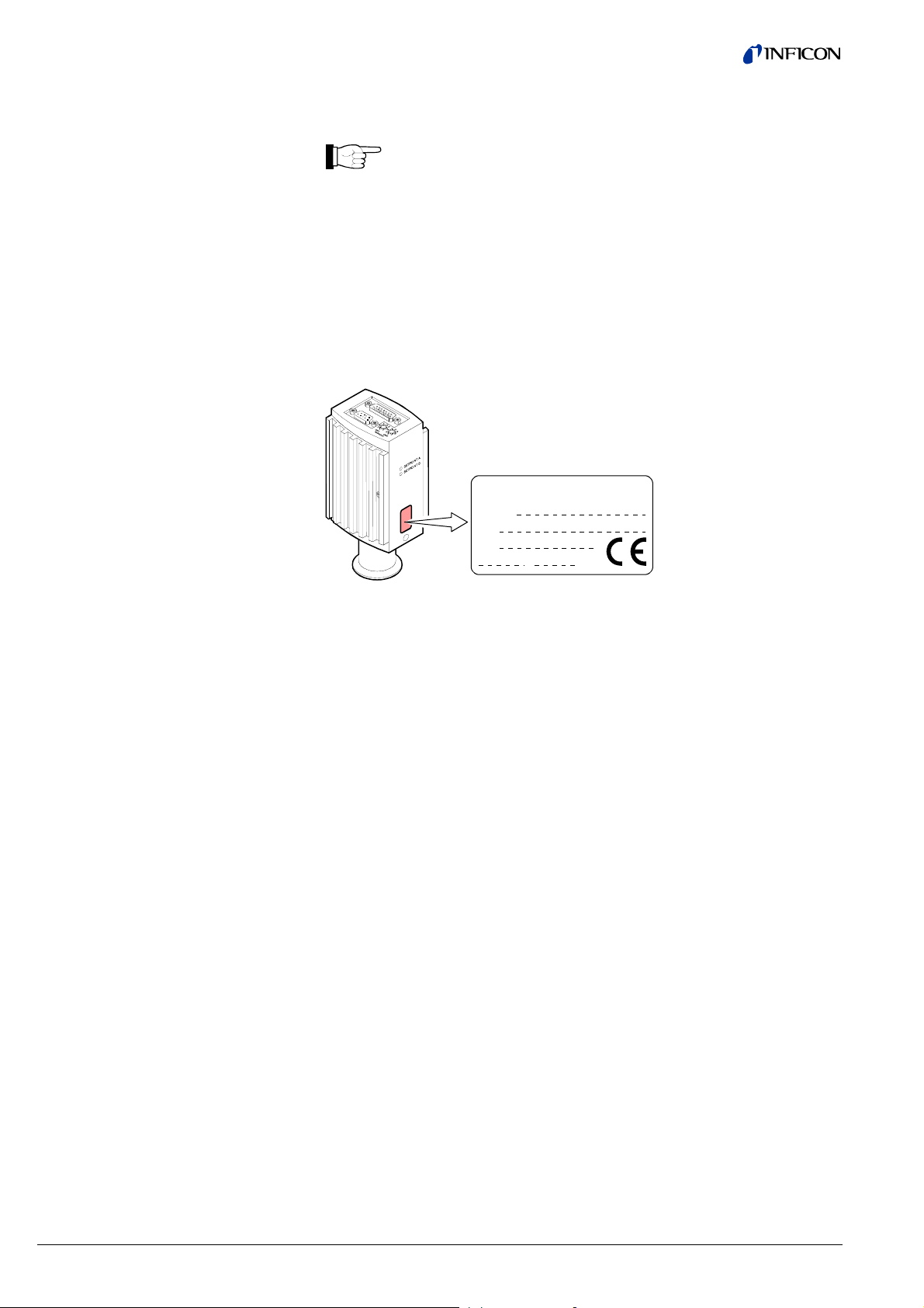
Product Identification
Validity
In all communications with INFICON, please specify the information on the product
nameplate. For convenient reference copy that information into the space provided
below.
INFICON AG, LI-9496 Balzers
Model:
PN:
SN:
V W
This document applies to products with part numbers
BCG450-SP (with Profibus interface and switching functions)
353-554
353-556 (vacuum connection DN 40 CF-R)
The part number (PN) can be taken from the product nameplate.
(vacuum connection DN 25 ISO-KF)
Intended Use
Functional Principle
Trademarks
The BCG450-SP gauge allows vacuum measurement of non flammable gases and
gas mixtures (pressure ranges → [1], [3]).
The gauges can be operated with an INFICON controller or another instrument or
control device.
The function of the gauge is described in the operating manual (→ [1], [2], [3]).
The integrated Profibus interface allows operating the gauge in connection with
other suitable devices in a Profibus network according to the standard described in
[4], [5].
®
SEMI
Profibus This document contains Profibus-specific information described and
Semiconductor Equipment and Materials International, California
defined in the Profibus standard EN 50170 (→ [5]).
2 tira41e1 (2005-06) BCG450SPv1.cp
Page 3

Contents
About this Document 2
Product Identification 2
Validity 2
Intended Use 2
Functional Principle 2
Trademarks 2
1 General Data 5
1.1 Data Rate 5
1.2 Device Address 5
1.3 Ident Number 5
1.4 Configuration Data 5
1.5 User Parameter Data 6
1.6 Types of Communication 6
2 Data Exchange Mode 7
2.1 Acyclic Data Transmission with Profibus DPV1 Functionality 7
2.2 Structure of the Cyclic Data Telegrams in Data Exchange Mode 8
2.2.1 Parameter Channel 9
2.2.1.1 PKE Parameter Signature Value 9
2.2.1.2 PWE Parameter (Process Value) 10
2.2.1.3 Error Code (Error Message) 10
2.3 Cyclic Message Telegrams 11
3 Block Model 12
3.1 Device Block 13
3.1.1 Information on the Individual Indices 14
3.1.1.1 Block Type ID 16 14
3.1.1.2 Device Type ID 17 14
3.1.1.3 Standard Revision Level ID 18 14
3.1.1.4 Device Manufacturer Identifier ID 19 14
3.1.1.5 Manufacturer Model Number ID 20 14
3.1.1.6 Software or Firmware Revision Level ID 21 14
3.1.1.7 Hardware Revision Level ID 22 14
3.1.1.8 Device Configuration ID 24 14
3.1.1.9 Device State ID 25 14
3.1.1.10 Exception Status ID 26 15
3.1.1.11 Exception Detail Alarm ID 27 16
3.1.1.12 Exception Detail Warning ID 28 18
3.1.1.13 Copy Common Exception Detail Alarm 0 ID 204 20
3.1.1.14 Copy Device Exception Detail Alarm 0 … 3 ID 205 20
3.1.1.15 Copy Device Exception Detail Alarm 4 … 5 ID 206 20
3.1.1.16 Copy Manufacturer Exception Detail Alarm 0 ID 207 21
3.1.1.17 Copy Common Exception Detail Warning 0 ID 208 21
3.1.1.18 Copy Device Exception Detail Warning 0 … 3 ID 209 21
3.1.1.19 Copy Device Exception Detail Warning 4 … 6 ID 210 21
3.1.1.20 Copy Manufacturer Exception Detail Warning 0 ID 211 21
3.1.2 Device Block, Device Behavior 21
3.1.2.1 Device Block State Command 22
3.2 Analog Input Block 23
3.2.1 One Of N Analog Input Function Block / SLOT 1 23
3.2.1.1 Block Type 23
3.2.1.2 Channel Instance Selector 23
3.2.1.3 PV Selector 23
3.2.2 Analog Sensor Input Function Block Instance 1 / SLOT 1 24
3.2.2.1 Process Value 24
3.2.2.2 Status 24
3.2.2.3 Data Type 24
3.2.2.4 Data Unit 25
3.2.2.5 Reading Valid 25
3.2.2.6 Full Scale 25
3.2.2.7 Safe State 26
3.2.2.8 Safe Value 26
3.2.2.9 Overrange 26
3.2.2.10 Underrange 26
3.2.3 Analog Sensor Input Function Block Instance 2 / SLOT 1 27
3.2.3.1 Process Value 27
3.2.3.2 Status 27
tira41e1 (2005-06) BCG450SPv1.cp 3
Page 4

3.2.3.3 Data Type 27
3.2.3.4 Data Unit 28
3.2.3.5 Reading Valid 28
3.2.3.6 Full Scale 28
3.2.3.7 Safe State 28
3.2.3.8 Safe Value 29
3.2.3.9 Overrange 29
3.2.3.10 Underrange 29
3.2.4 Analog Sensor Input Function Block Instance 3 / SLOT 1 30
3.2.4.1 Process Value 30
3.2.4.2 Status 30
3.2.4.3 Data Type 30
3.2.4.4 Data Unit 31
3.2.4.5 Reading Valid 31
3.2.4.6 Full Scale 31
3.2.4.7 Safe State 32
3.2.4.8 Safe Value 32
3.2.4.9 Overrange 32
3.2.4.10 Underrange 32
3.2.5 Analog Sensor Input Function Block Instances 5 and 6 / SLOT 1 33
3.2.5.1 Process Value 33
3.2.5.2 Status 34
3.2.5.3 Data Type 34
3.2.5.4 Data Unit 34
3.2.5.5 Reading Valid 34
3.2.5.6 Setpoint Function 34
3.2.5.7 "Percentage of Atmosphere" 34
3.2.5.8 Atmosphere Reached 36
3.3 Transducer Block 36
3.3.1 One Of N Vacuum Gauge Transducer Block / SLOT 1 36
3.3.1.1 One Of N Status Extension 36
3.3.2 Heat Transfer Vacuum Gauge Transducer Block / SLOT 1 / Instance 1 36
3.3.2.1 Block Type 36
3.3.2.2 Status Extension 36
3.3.2.3 Sensor Alarm 36
3.3.2.4 Sensor Warning 37
3.3.3 Hot Cathode Ion Gauge Transducer Block / SLOT 1 / Instance 2 37
3.3.3.1 Block Type 37
3.3.3.2 Status Extension 37
3.3.3.3 Sensor Alarm 37
3.3.3.4 Sensor Warning 38
3.3.3.5 Emission Status 38
3.3.3.6 Emission Current 38
3.3.3.7 Degas Status 38
3.3.3.8 Emission User Mode State 38
3.3.3.9 Hot Cathode Block State Command 39
3.3.4 Diaphragm Gauge Transducer Block / SLOT 1 / Instance 3 40
3.3.4.1 Block Type 40
3.3.4.2 Status Extension 40
3.3.4.3 Sensor Alarm 40
3.3.4.4 Sensor Warning 40
3.3.4 Atmosphere Sensor Transducer Block
(Piezo Sensor) / SLOT 1 / Instance 4 41
3.3.4.1 Block Type 41
3.3.4.2 Atmosphere Sensor Block State Command 41
Appendix A: Definitions 42
Appendix B: Block Type 45
Appendix C: Electrical Connections 46
Appendix D: Literature 48
For cross-references to other documents, the symbol (→ [XY]) is used.
4 tira41e1 (2005-06) BCG450SPv1.cp
Page 5
1 General Data
1.1 Data Rate
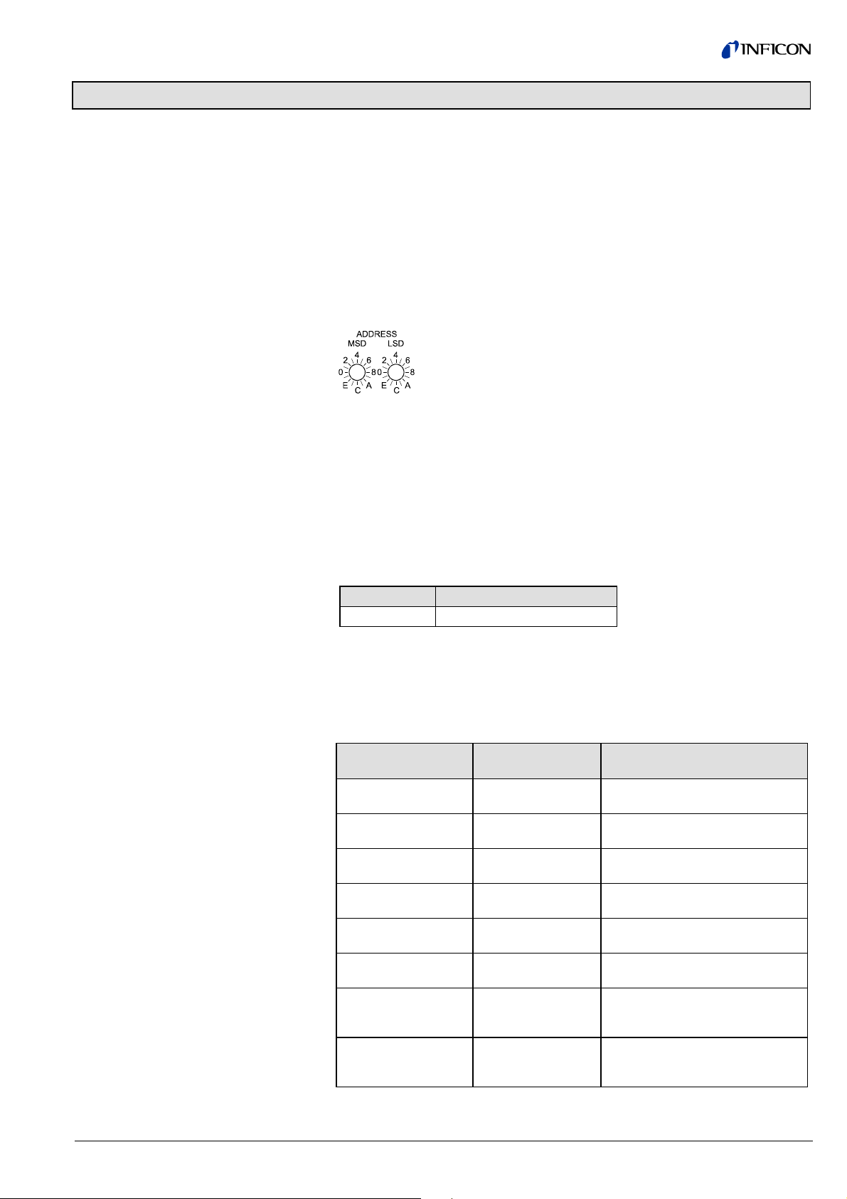
1.2 Device Address
The gauge supports all data rates defined in the EN 50170 standard (→ [5]) up
to 12 Mbaud. Automatic data rate setting is supported. Alternatively, a fixed data
rate can be selected.
The device address ( node address) must be set via two rotary switches when the
gauge is installed.
For unambiguous identification of the gauge in a Profibus environment, a node
address is required. The node address setting is made on the gauge.
The node address (0 … 125
(00 … 7D
) (default value 5C
hex
) is set in hexadecimal form
dec
) via the "ADDRESS" switches.
hex
The "MSD" switch is used for setting the high-order address
nibble and the "LSD" switch for defining the low-order address
nibble.
The node address is polled by the firmware when the gauge is switched on. If the
setting deviates from the stored value, the new value is taken over into the
NVRAM. If a value >7D
hex
(>125
) is entered, the node address setting currently
dec
stored in the device remains valid. However, the address can be set via the
Profibus master with the "Set Slave Address" service. This address setting will be
stored in the EEPROM of the gauge.
1.3 Ident Number
1.4 Configuration Data
The ident number assigned to the gauge by the PNO (→ [4]) is:
Gauge Ident number (hexadecimal)
BCG450-SP 08E6
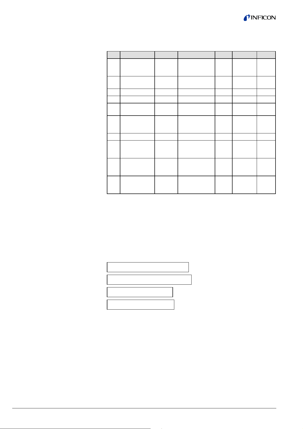
Depending on the standard telegrams used (→ section "Cyclic Message Telegrams"), the following configuration data have to be transmitted to the gauge during
the configuration phase:
Standard telegram
Master ⇒ Slave
Standard telegram
Slave ⇒ Master
Configuration data
- 4 0x44, 0x84, 0x05, 0x05, 0x05,
0x03
- 5 0x44, 0x86, 0x05, 0x05, 0x05,
0x08
1 4 0xC6, 0x81, 0x84, 0x05, 0x05,
0x05, 0x05, 0x05, 0x03
1 5 0xC6, 0x81, 0x86, 0x05, 0x05,
0x05, 0x05, 0x05, 0x08
3 6 0xC6, 0x87, 0x8C, 0x0A, 0x0A,
0x05, 0x05, 0x05, 0x03
3 7 0xC6, 0x87, 0x8E, 0x0A, 0x0A,
0x05, 0x05, 0x05, 0x08
2 6 0xC8, 0x89, 0x8C, 0x0A, 0x05,
0x05, 0x0A, 0x05, 0x05, 0x05,
0x03
2 7 0xC8, 0x89, 0x8E, 0x0A, 0x05,
0x05, 0x0A, 0x05, 0x05, 0x05,
0x08
tira41e1 (2005-06) BCG450SPv1.cp 5
Page 6

1.5 User Parameter Data
Depending on the pressure unit setting ( data unit), the following configuration
string has to be transmitted to the gauge (parameter data in hexadecimal format):
1.6 Types of
Communication
Pressure unit User parameter data string
COUNTS
Torr 00 00 00 05 15
Micron 00 00 00 05 16
mbar 00 00 00 05 1C
Pascal 00 00 00 05 1D
1)
If COUNTS is selected as pressure unit, a value is output, which can be converted into a corresponding pressure value by means of a formula (→ section
"Analog Sensor Input Function Block" for more information).
BCG450-SP works according to the Profibus DPV1 specification and can be
addressed in cyclic or acyclic data traffic (→ [4]).
Acyclic data traffic should be used to make device or process specific settings such
as definition of the Safe Values, Safe States etc. or for reading or writing of rarely
used attributes.
Cyclic data traffic is used for continuous exchange of the required process parameter values, i.e. pressure value and status indications. A number of standard
telegrams are available for cyclic data traffic. They can be selected according to
requirements (→ section "Cyclic Message Telegrams").
1)
00 00 00 03 E9
6 tira41e1 (2005-06) BCG450SPv1.cp
Page 7
2 Data Exchange Mode
2.1 Acyclic Data Transmission with Profibus
DPV1 Functionality
Block, slot and
index assignment
The reading and writing operations defined in Profibus are based on a slot index
address scheme. In BCG450-SP, all device functions are organized in the following
blocks:
• A device block describing all organizational parameters of the gauge (serial
number, manufacturer, software version, …)
• An Analog Sensor Function Block describing the function of the pressure presentation
• An Analog Sensor Transducer Block describing the physical interface between
the gauge and the process (emission current, ion current, …).
The block model is described in detail in section "Block Model".
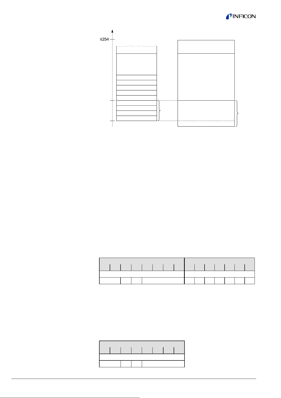
Each block is assigned to a separate slot. The exact assignment
Block ⇒ Slot ⇒ Index is described in section "Block Model". The Device Block is
assigned to Slot 0, the transducer and functional blocks to Slot 1.
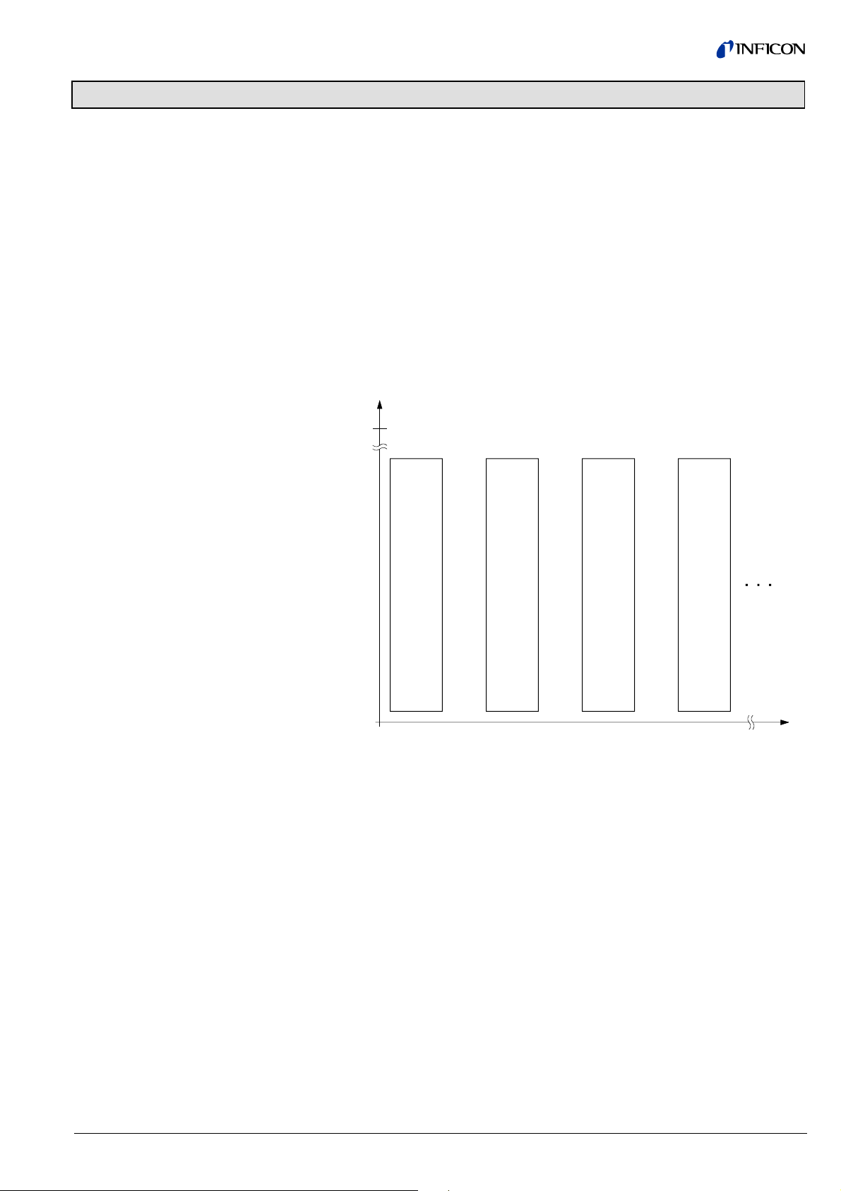
Index
254
Device
Block
Block_1 Block_2 Block_3
0
There are 254 indices per slot. The indices can have a width of 255 bytes. All values that can be accessed via Profibus have to be mirrored to one of these slots/
indices.
The parameters are generally numbered in ascending order, starting with index 16.
Services such as "Degas On" or "Full scale" are numbered in descending order,
starting with index 15.
0123
tira41e1 (2005-06) BCG450SPv1.cp 7
Page 8
Assignment of the block
elements to the slot indices
Index
2.2 Structure of the Cyclic
Data Telegrams in
Data Exchange Mode
Parameter_n
Block_x
Parameter_2
Parameter_1
16
0
In Data Exchange mode, the DP master class 1 cyclically transmits data from and
to all slaves that are connected to the bus.
In this document, data transmitted from the slave to the master are called "input
data" and data transmitted from the master to the slave are called "output data".
The input and output data of the BCG450-SP has two logic parts:
1) the parameter channel
2) the process data channel
There is a number of standard telegrams, consisting of:
a) the parameter channel only
b) the process data channel only
c) both, the parameter and process data channel
The parameter channels allows masters without Profibus DPV1 to access device
specific parameters that are not part of the normal cyclic data telegram. For masters with Profibus DPV1, no parameter channel is required.
Parameter_0
Operation_1
Operation_2
Operation_n
optional
Block_Type_Name
Attributes
Public
Operations Public
optional
Private
Input data
Output data
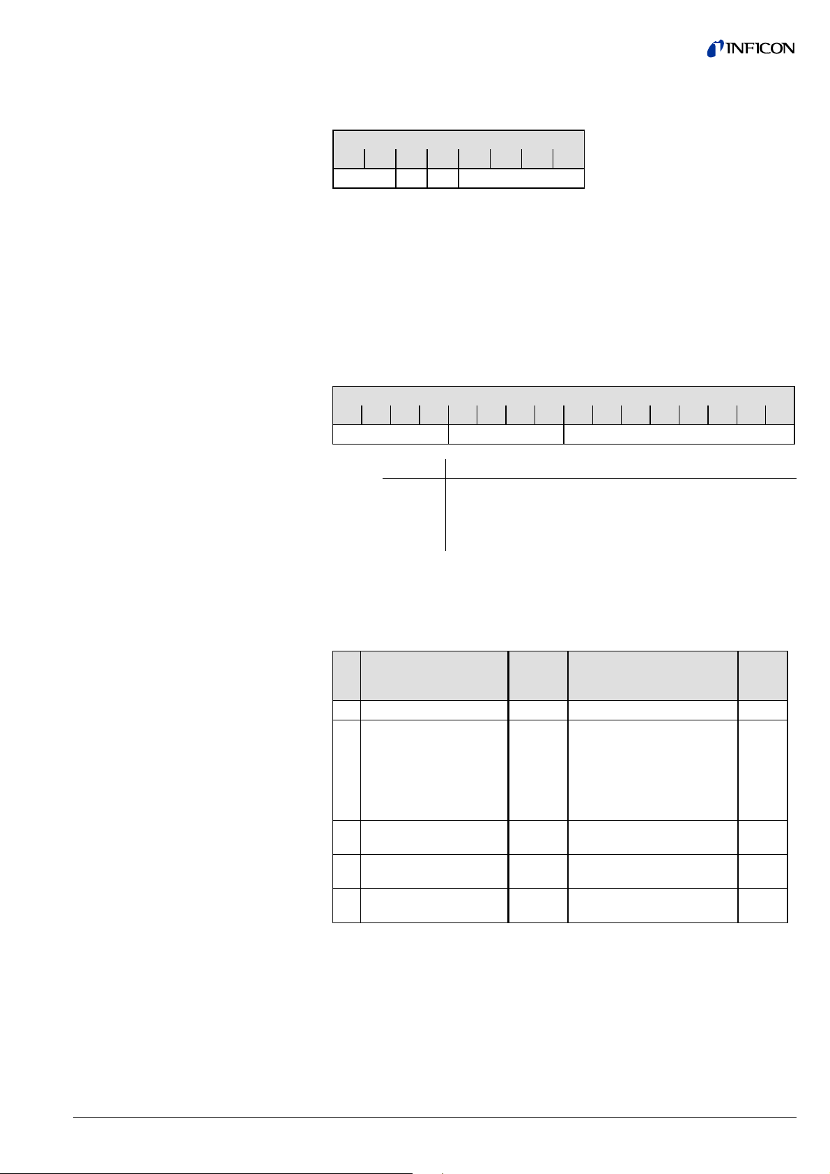
The input data (transmitted by the BCG450-SP) consists of the 8 bytes of the parameter channel (if there is a parameter channel in the standard telegram) and of
5 … 7 bytes of process data depending on the selected standard telegram.
Byte Byte
1 2 3 4 5 6 7 8 9 10 11 12 13 14 15
Parameter channel Process data
PKE IND res. PWE
Where: PKE = Parameter Signature Value
IND = Sub Index
res. = reserved
PWE = Process Value
The output data (transmitted by the master) consist of 8 bytes of the parameter
channel or, if there is no parameter channel in the standard telegram, of 0 bytes.
Byte
1 2 3 4 5 6 7 8
Parameter channel
PKE IND res. PWE
Reading or writing command and definition of the slot
Index No. of the index to be
read (→ "Block Model")
Value to be read or written
8 tira41e1 (2005-06) BCG450SPv1.cp
Page 9
2.2.1 Parameter Channel
The structure of the parameter channel is described in the table below.
The parameter channel (called PKW Interface hereinafter) consists of 8 bytes.
Octets
1 2 3 4 5 6 7 8
PKE IND res. PWE
The PKW Interface allows reading and writing of slave parameters with a maximum
data length of 4 bytes. Strings cannot be read.
The slave generates exactly one response per instruction transmitted by the master. The instruction and response cannot be blocked. This means that exactly one
instruction per output telegram can be transmitted to the slave and that exactly one
response per input telegram can be transmitted to the master. 4 bytes of actual
data can thus be transmitted at a time.
2.2.1.1 PKE Parameter
Signature Value
Instruction signature
The instruction and response are represented in the first two bytes (PKE) of the
parameter channel:
Bit position
15 14 13 12 11 10 9 8 7 6 5 4 3 2 1 0
AK res. Slot
Where: Bits Meaning
15 … 12
AK Instruction/response signature
11 … 8 Reserved
7 … 0 Define the slot from which data are read or onto which a
value is to be written
In Master ⇒ Slave communication, the AK field contains the instruction signature of
the master.
In Slave ⇒ Master communication, the AK field contains the instruction signature of
the slave.
AK Function
Master ⇒ Slave
(Instruction signature)
AK
normal
Function
Slave ⇒ Master
(Response signature)
AK
error
0 No instruction 0 No response
1 Read parameter value 1
Transmit parameter value
7
1)
(word)
2
Transmit parameter value
(double word)
11
Transmit parameter value
(byte)
2 Write parameter value
1 Transmit parameter value
(data type: word)
3 Write parameter value
2 Transmit parameter value
(data type: double word)
10 Write parameter value
11 Transmit parameter value
(data type: byte)
1)
Instruction cannot be executed (error code)
(word)
(double word)
(byte)
7
7
7
1)
1)
1)
On the left of the table, the instruction signatures of the master are listed according
to their function. On the right of the table, the corresponding normal responses (AK
Normal) and error codes (AK Error) transmitted by the slave are listed.
tira41e1 (2005-06) BCG450SPv1.cp 9
Page 10
Instruction – response
sequence
1) The master transmits an instruction to the slave and repeats that instruction
until it receives a response from the slave.
2) The slave keeps transmitting the response to the instruction until the master
transmits a new instruction.
3) The master marks the end of the first instruction cycle by setting AK to zero.
Only after that, a new instruction/response cycle may be started.
2.2.1.2 PWE Parameter
(Process Value)
2.2.1.3 Error Code
(Error Message)
The PWE represents the data element to be transmitted.
If a byte is to be transmitted, that byte has to be in position 8 of the parameter
channel.
Integers are transmitted with bytes 7 and 8. Double integer and float values are
transmitted with bytes 5 … 8.
In the event of a transmission error (AK response signature = 7), the slave transmits an error code in byte positions 7 and 8 (data type: INT16).
Error code Meaning
0 Undefined slot
1 Parameter not changeable
2 Lower or upper value range limit overflow
3 Index error
5 Data type error
17 Instruction not allowed in this state
18 Other errors
201 Already in requested state
202 Object state conflict
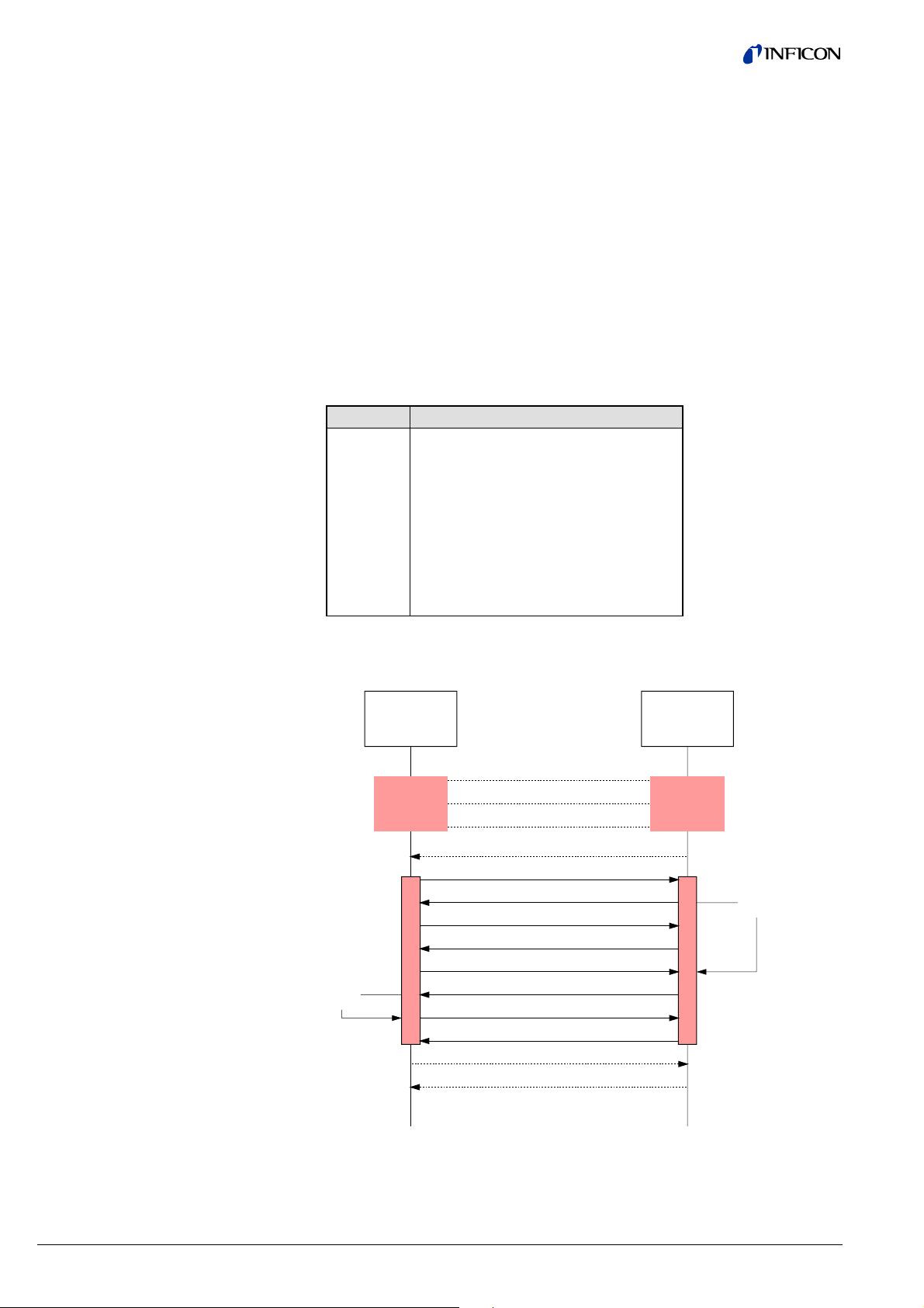
The following diagram shows an example of a data request from a master to a
BCG450-SP via parameter channel.
Store
Data
DP-Master
Parameter
Request
(Client)
AK(IS) = 0
AK(RS) = 0
AK(IS) = 0
AK(RS) = 0
AK (IS) = 1
AK(RS) = 0
AK (IS) = 1
AK(RS) = 0
AK (IS) = 1
AK(RS) = 1
AK (IS) = 0
AK(RS) = 0
AK (IS) = 0
AK(RS) = 0
BCG450-SP
Parameter
Request
(Server)
Fetch
Data
10 tira41e1 (2005-06) BCG450SPv1.cp
Page 11
2.3 Cyclic Message
Telegrams
The message telegrams listed below are implemented in the gauge. They can be
selected according to requirements. When selecting a message telegram, ascertain
what output format of the measured value (integer/float) is required and whether a
parameter channel is needed or not. The gauge can also be operated in such a
way that the master does not transmit any output data to the slave.
Standard
telegram
1
2
3
4
5
6
7
Master
⇔
Slave
M ⇒ S
M ⇒ S
M ⇒ S
S ⇒ M
S ⇒ M
S ⇒ M
S ⇒ M
Byte Meaning
1 Transition Command
2 Transition Command Value for Hot Ion Gauges
1 … 8 Parameter Channel
9 Transition Command
10 Transition Command Value for Hot Ion Gauges
1 - 8 Parameter Channel
1 Exception status
2 One Of N status extension
3 One Of N PV selector
4 … 5 Process value UINT16
1 Exception status
2 One Of N status extension
3 One Of N PV selector
4 … 7 Process value float
1 … 8 Parameter channel
9 Exception status
10 One Of N status extension
11 One Of N PV selector
12 … 13 Process value UINT16
1 … 8 Parameter channel
9 Exception status
10 One Of N status extension
11 One Of N PV selector
12 … 15 Process value float
Configuration data
In the following table, the possible reasonable combinations are listed with the
corresponding configuration data.
Standard telegram
Master ⇒ Slave
- 4 0x44, 0x84, 0x05, 0x05, 0x05, 0x03
- 5 0x44, 0x86, 0x05, 0x05, 0x05, 0x08
1 4 0xC6, 0x81, 0x84, 0x05, 0x05, 0x05,
1 5 0xC6, 0x81, 0x86, 0x05, 0x05, 0x05,
3 6 0xC6, 0x87, 0x8c, 0x0A, 0x0A, 0x05,
3 7 0xC6, 0x87, 0x8E, 0x0A, 0x0A,
2 6 0xC8, 0x89, 0x8c, 0x0A, 0x05, 0x05,
2 7 0xC8, 0x89, 0x8E, 0x0A, 0x05, 0x05,
Standard
telegram
Slave ⇒ Master
Configuration data
0x05, 0x05, 0x03
0x05, 0x05, 0x08
0x05, 0x05, 0x03
0x05, 0x05, 0x05, 0x08
0x0A, 0x05, 0x05, 0x05, 0x03
0x0A, 0x05, 0x05, 0x05, 0x08
tira41e1 (2005-06) BCG450SPv1.cp 11
Page 12

3 Block Model
Data to the BCG450-SP can be transmitted by means of a number of communication protocols and corresponding masters. Profibus defines a master class 1 as
normal control unit of the slave (typically a PLC) and a master class 2 as configuration and service unit. The following communication protocols are defined according
to the Profibus DPV1 standard.
MS0 Cyclic data traffic between master class 1 and slave
MS1 Acyclic data traffic between master class 1 and slave
MS2 Acyclic data traffic between master class 2 and slave
In the BCG450-SP, all functions that are made available by the gauge via Profibus
are organized in blocks. Access to the individual parameters of the blocks is possible via acyclic services or, for byte, integer and float values, also in cyclic data
traffic via the parameter channel.
Block types
The following block types are defined in the gauge.
Device Block The Device Block contains all data that are required for de-
scribing the device and handling its state (status of Device
State Machine).
Transducer Block The physical, process specific functions or interfaces between
the BCG450-SP and the process such as current and voltage
values are represented in transducer blocks.
The following transducer blocks are implemented:
• One of N Vacuum Gauge Transducer Block
• Heat Transfer Vacuum Gauge Transducer Block (Pirani)
• Hot Cathode Ion Gauge Transducer Block (BA)
• Diaphragm Gauge Transducer Block (CDG)
Function Block Application specific values such as pressure values that result
from or can be calculated from the values of the transducer
block are represented in the function blocks.
• One of N Analog Input Function Block
• Analog Input Function Block, Instance 1, Instance 2,
Instance 3, Instance 4, Instance 5, Instance 6.
12 tira41e1 (2005-06) BCG450SPv1.cp
Page 13
3.1 Device Block
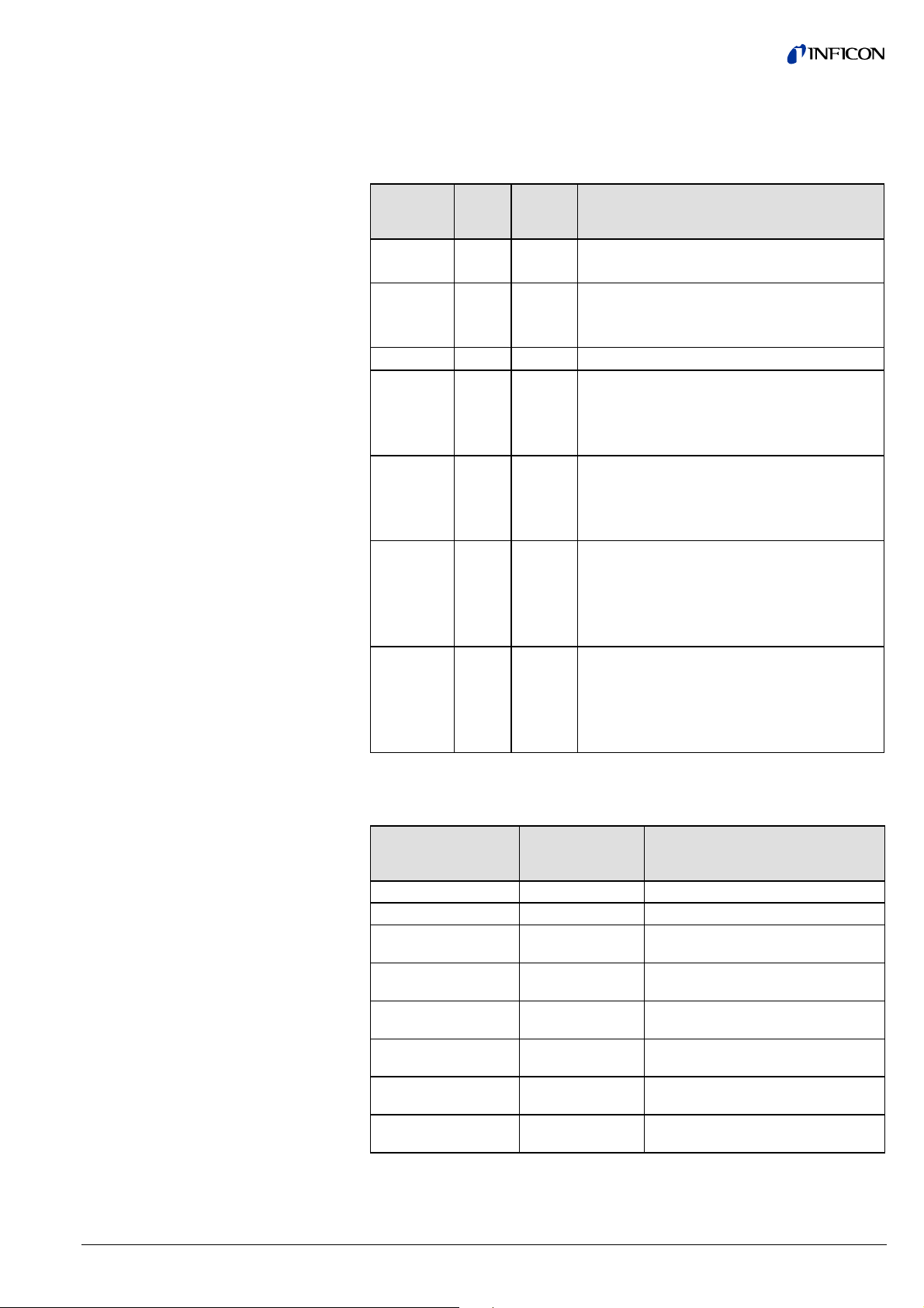
The following table lists the services and parameters integrated in the Device Block
(→ Appendix A for abbreviations).
ID Name Structure Data type Bytes Access Value Store
15 Device Block State Simple Unsigned8 1 1_R/W
2_R/W
16 Block Type Simple Octet string 4 1/2_R 1 N
17 Device Type Simple Visible string 8 1/2_R CG N
18 Standard Revision Level Simple Visible string 9 1/2_R E54-0997 N
19 Device Manufacturer
Simple Visible string 20 1/2_R INFICON AG N
Identifier
20 Manufacturer
Model Number
21 Software or Firmware
Simple Visible string 20 1/2_R e.g.
353-554
Simple Visible string 8 1/2_R e.g. 1.01 N
Revision Level
22 Hardware Revision Level Simple Visible string 8 1/2_R e.g. 1.0 N
23 Serial Number Simple Visible string 30 1/2_R e.g. 100 N
24 Device Configuration Simple Visible string 50 1/2_R e.g.
BCG450-SP
25 Device State Simple Unsigned8 1 1/2_R V
26 Exception Status Simple Unsigned8 1 0_XI
V
1/2_R
27 Exception Detail Alarm Record
28 Exception Detail
Record
→ below
→ below
- 1/2_R V
- 1/2_R V
Warning
204 Common Exception
Simple UINT8 1 1/2_R V
Detail Alarm 0
205 Device Exception Detail
Alarm 0 … 3
206 Device Exception Detail
Alarm 4 … 5
207 Manufacturer Exception
Struct Array of
4 1/2_R V
4 bytes
Struct Array of
2 1/2_R V
2 bytes
Simple UINT8 1 1/2 _R V
Detail Alarm 0
208 Common Exception
Simple UINT8 1 1/2 _R V
Detail Warning 0
209 Device Exception Detail
Warning 0 … 3
210 Device Exception Detail
Warning 4 … 6
211 Manufacturer Exception
Struct Array of
4 1/2 _R V
4 bytes
Struct Array of 3
3 1/2_R V
bytes
Simple UINT8 1 1/2_R V
Detail Warning 0
N
N
tira41e1 (2005-06) BCG450SPv1.cp 13
Page 14

3.1.1 Information on the
Individual Indices
3.1.1.1 Block Type ID 16
3.1.1.2 Device Type ID 17
3.1.1.3 Standard Revision Level
ID 18
3.1.1.4 Device Manufacturer
Identifier ID 19
3.1.1.5 Manufacturer Model
Number ID 20
3.1.1.6 Software or Firmware
Revision Level ID 21
3.1.1.7 Hardware Revision Level
ID 22
3.1.1.8 Device Configuration ID 24
3.1.1.9 Device State ID 25
The Block Type Parameter contains an ID which describes the block type. The
block type ID of the Device Block 1. The other defined block types are listed in
Appendix B.
The Device Type identifies the device type which is connected to the field bus via
Profibus.
The Device Type of the BCG450-SP gauge is "CG", the abbreviation of
"Combination Gauge".
This parameter describes the version of the "Sensor/Actuator Network Specific
Device Model" published by the SEMI
®
(Semiconductor Equipment and Materials
International, California), according to which the profile of this device has been
developed.
The fixed setting of this parameter is "E54-0997".
This parameter describes the manufacturer of the device, "INFICON AG".
This parameter represents the part number of the gauge (→ section "Validity").
BCG450-SP is available with two different vacuum connection types each, for ex-
ample:
Gauge Vacuum connection Part number
BCG450-SP 25 KF 353-554
This parameter indicates the software version of the Profibus option in the following
format: xxx_y.yy (where xxx is the version of the BCG450 firmware and y.yy is the
version of the profibus board).
This parameter indicates the hardware version of the gauge in the format "1.0".
This parameter indicates the device name.
This parameter indicates the status of the gauge. Due to the structure of the Device
State Machine, the following statuses are possible:
Parameter value Status
0 Undefined
1 Self testing
2 Idle
3 Self test exception
4 Executing
5 Abort
6 Critical fault
The device statuses are described in detail in section "Device Block, Device
Behavior".
14 tira41e1 (2005-06) BCG450SPv1.cp
Page 15

3.1.1.10 Exception Status ID 26
The Exception Status describes the alarm and warning states of the gauge in an
"Expanded error output format".
A difference is made between warnings and errors.
Alarms and errors are divided into three groups (→ sections "Exception Detail
Alarm" and "Exception Detail Warning" for details):
• ALARM / Warning Device Common
For errors that occur independently of
the type of device used, e.g. supply
error, RAM, ROM, or EEPROM error.
• ALARM / Warning Device Specific
For device specific errors, e.g. filament
rupture (Pirani), or cathode rupture
(BA).
• ALARM / Warning Manufacturer
Specific
For errors defined by the manufacturer
that are not mentioned in the standard.
In each of the above groups, there are several error or warning conditions. The individual fields are presented in the "Exception Detail Alarm" and "Exception Detail
Warning". If an error message occurs in "Exception Detail Alarm" or "Exception
Detail Warning”, the corresponding bit is set in the Exception Status. Therefore, if
bits 0 … 6 of the Exception Status are on "0" there is no warning message pending.
If a bit is set, the actual error can be read in the corresponding group.
The Exception Status is output in cyclic data and informs on the current error status
using only one byte. If an error occurs, the current error status can be read via
acyclic services or in cyclic data exchange via the parameter channel. This ensures
that while the current error status is always available in the cyclic data, no unnecessary data overhead is transmitted.
Bit Function Meaning
0 ALARM, device common The bit is set if an error of the Alarm
Device Common group is detected.
1 ALARM, device specific The bit is set if an error of the Alarm
Device Specific group is detected.
2 ALARM, manufacturer specific The bit is set if an error of the Alarm
Manufacturer Specific group is detected.
3
- -
4 WARNING, device common The bit is set if an error of the Warning
Device Common group is detected.
5 WARNING, device specific The bit is set if an error of the Warning
Device Specific group is detected.
6 WARNING, manufacturer
specific
The bit is set if an error of the Warning
Manufacturer Common group is detected.
7 Expanded Format Is constantly on "1" and marks the use of
the expanded error output format.
tira41e1 (2005-06) BCG450SPv1.cp 15
Page 16
3.1.1.11 Exception Detail Alarm
ID 27
If, in the Exception Status, one of the bits 0 … 2 is set, the current error can be
read in the "Exception Detail Alarm" parameter. The "Exception Detail Alarm" parameter consists of a total of 12 bytes that inform on the error status of the gauge.
Due to the use of the expanded error output format, these bytes have the following
structure:
ByteNo Name Description Value
Common Exception
Detail Alarm
0
Common Exception
Detail Size
Indicates the number of subsequent bytes that contain the
Common Exception Detail Alarm.
1 Common Exception
Detail 0
Contains current error messages
from the Common Exception
Depending on
error status
Detail Alarm group.
2 Common Exception
Detail 1
Contains current error messages
from the Common Exception
Detail Alarm group.
Depending on
error status
3
Device Exception
Detail Size
Indicates the number of subsequent bytes that contain the
Device Exception Detail Alarm.
4 Device Exception
Detail 0
(CDG error data)
This error information from the
Common Exception Detail Alarm
group refers to Capacitance
Depending on
error status
Diaphragm gauge.
5 Device Exception
Detail 1
(CDG error data)
This error information from the
Common Exception Detail Alarm
group refers to Capacitance
Depending on
error status
Diaphragm gauge.
6 Device Exception
Detail 2
(Pirani error data)
7 Device Exception
Detail 3
(Pirani error data)
8 Device Exception
Detail 4
(BA error data)
9 Device Exception
Detail 5
(BA error data)
10
Manufacturer
Exception Detail
Size
11 Manufacturer
Exception Detail 0
This error information from the
Common Exception Detail Alarm
group refers to Pirani.
This error information from the
Common Exception Detail Alarm
group refers to Pirani.
This error information from the
Common Exception Detail Alarm
group refers to BA.
This error information from the
Common Exception Detail Alarm
group refers to BA.
Indicates the number of subsequent bytes that contain the
Device Exception Detail Alarm.
Contains current error messages
from the Manufacturer Exception
Depending on
error status
Depending on
error status
Depending on
error status
Depending on
error status
Depending on
error status
Detail Alarm group.
Bit Common Exception Detail 0 Bit Common Exception Detail 1
0 0 0 0
1 0 1 0
2 EPROM exception 2 0
3 EPROM exception 3 0
4 RAM exception 4 0
5 0 5 0
6 0 6 0
7 0 7 0
2
7
1
16 tira41e1 (2005-06) BCG450SPv1.cp
Page 17

Device Exception
Detail Alarm
Manufacturer Exception
Detail Alarm 0
Bit Device Exception Detail 0
Referring to Capacitance
diaphragm sensor
Bit Device Exception Detail 1
Referring to Capacitance
diaphragm sensor
0 Diaphragm Failure 0 0
1 0 1 Electronics/sensor error
2 0 2 0
3 0 3 0
4 0 4 0
5 0 5 0
6 0 6 0
7 0 7 0
This byte is a copy of Sensor Alarm
byte 0 of Capacitance diaphragm
sensor Transducer Block.
This byte is a copy of Sensor Alarm
byte 1 of Capacitance diaphragm
sensor Transducer Block.
Bit Device Exception Detail 2
Referring to Pirani
Bit Device Exception Detail 3
Referring to Pirani
0 0 0 0
1 0 1 Electronics/sensor error Pirani
2 0 2 0
3 0 3 0
4 0 4 0
5 0 5 0
6 0 6 0
7 0 7 0
This byte is a copy of Sensor Alarm
byte 0 of the Heat Transfer Vacuum
Gauge Transducer Block.
This byte is a copy of Sensor Alarm
byte 1 of the Heat Transfer Vacuum
Gauge Transducer Block.
Bit Device Exception Detail 4
Referring to BA
Bit Device Exception Detail 5
Referring to BA
0 0 0 0
1 0 1
Electronics/sensor error BA
2 0 2 0
3 0 3 0
4 0 4 0
5 0 5 0
6 0 6 0
7 0 7 0
This byte is a copy of Sensor Alarm
byte 0 of the Hot Cathode Ion Gauge
Transducer Block.
This byte is a copy of Sensor Alarm
byte 1 of the Hot Cathode Ion Gauge
Transducer Block.
Manufacturer Exception Detail 0 is set to "1", if there is an internal communication
error in the gauge.
tira41e1 (2005-06) BCG450SPv1.cp 17
Page 18

3.1.1.12 Exception Detail Warning
ID 28
If, in the Exception Status, one of bits 4 … 6 is set, the current warning can be read
in the parameter "Exception Detail Warning". The Exception Detail Warning parameter consists of a total of 13 bytes that inform on the error status of the gauge.
Due to the use of the expanded error output format, these bytes have the following
structure:
ByteNo Name Description Value
0
Common Exception
Detail Size
1 Common Exception
Detail 0
2 Common Exception
Detail 1
3
Device Exception
Detail Size
4 Device Exception
Detail 0
5 Device Exception
Detail 1
(Capacitance
diaphragm sensor)
6 Device Exception
Detail 2
(Capacitance
diaphragm sensor)
7 Device Exception
Detail 3
(Pirani)
8 Device Exception
Detail 4
(Pirani)
9 Device Exception
Detail 5
(BA)
10 Device Exception
Detail 6
(BA)
11
Manufacturer
Exception Detail
Size
12 Manufacturer
Exception Detail
Indicates the number of subsequent bytes that contain the
2
Common Exception Detail
Warning.
Contains current error messages
from the Common Exception
Depending on
warning status
Detail Warning group.
Contains current error messages
from the Common Exception
Depending on
warning status
Detail Warning group.
Indicates the number of subsequent bytes that contain the
5
Device Exception Detail Warning.
One of N Status Extension. Depending on
warning status
This error information from the
Common Exception Detail
Depending on
warning status
Warning group refers to
Capacitance diaphragm sensor.
This error information from the
Common Exception Detail
Depending on
warning status
Warnings group refers to
Capacitance diaphragm sensor.
This error information from the
Common Exception Detail Alarm
Depending on
warning status
group refers to Pirani.
This error information from the
Common Exception Detail Alarm
Depending on
warning status
group refers to Pirani.
This error information from the
Common Exception Detail Alarm
Depending on
warning status
group refers to BA.
This error information from the
Common Exception Detail Alarm
Depending on
warning status
group refers to BA.
Indicates the number of subsequent bytes that contain the
1
Device Exception Detail Warning.
Contains current error messages
from the Manufacturer Exception
Depending on
warning status
Detail Alarm group.
18 tira41e1 (2005-06) BCG450SPv1.cp
Page 19

Common Exception
Detail Warning
Device Exception
Detail Warning
Bit Common Exception Detail 0 Bit Common Exception Detail 1
0 0 0 0
1 0 1 0
2 EPROM exception 2 0
3 EPROM exception 3 0
4 RAM exception 4 0
5 0 5 0
6 0 6 0
7 0 7 0
The warning bits are set in the same way as the error bits because here, warnings
have the same meaning as errors.
Bit Device Exception Detail 0 Bit Device Exception Detail 1
Referring to CDG
0 Bit set if
0 0
Reading Invalid
1 Bit set if
1 0
Device Overrange
2 Bit set if
2 0
Device Underrange
3 0 3 0
4 0 4 0
5 0 5 0
6 0 6 0
7 0 7 0
This byte is a copy of the One Of N
Vacuum Gauge Transducer Block.
This byte is a copy of Sensor
Warning byte 0 of Capacitance
diaphragm sensor Transducer Block
Sensor Warning Byte 0.
Bit Device Exception Detail 2
Referring to CDG
Bit Device Exception Detail 3
Referring to Pirani
0 0 0 0
1 Electronics/Sensor Warning 1 0
2 0 2 0
3 0 3 0
4 0 4 0
5 0 5 0
6 0 6 0
7 0 7 0
This byte is a copy of Sensor
Warning byte 1 of Capacitance
diaphragm sensor Transducer Block.
This byte is a copy of Sensor
Warning byte 0 of the Heat Transfer
Vacuum Gauge Transducer Block.
tira41e1 (2005-06) BCG450SPv1.cp 19
Page 20

Manufacturer Exception
Detail Warning
Device Exception Detail 4
Bit
Referring to Pirani
Device Exception Detail 5
Bit
Referring to BA
0 0 0 0
1 Electronics/sensor warning
1 0
Pirani
2 0 2 0
3 0 3 0
4 0 4 0
5 0 5 0
6 0 6 0
7 0 7 0
This byte is a copy of Sensor
Warning byte 1 of the Heat Transfer
Vacuum Gauge Transducer Block.
Device Exception Detail 6
Bit
Referring to BA
This byte is a copy of Sensor
Warning byte 0 of the Hot Cathode
Ion Gauge Transducer Block.
0 0
1 Electronics/sensor warning
2 0
3 Pressure too high for degas
4 0
5 0
6 0
7 0
This byte is a copy of Sensor
Warning byte 1 of the Hot Cathode
Ion Gauge Transducer Block.
Bit Manufacturer Exception Detail Warning
0 0
1 Relay A set if atmospheric pressure is reached.
2 Relay B set if atmosphere pressure is reached.
3 0
4 0
5 0
6 0
7 0
The following parameters are copies of the ID 27 and ID 28. They are
used only if you want to access these parameters by the parameter
channel.
3.1.1.13 Copy Common Exception
Detail Alarm 0
ID 204
3.1.1.14 Copy Device Exception
Detail Alarm 0 … 3
This parameter corresponds to the Common Exception Detail Alarm of the
Exception Detail Alarm (ID 27).
This parameter corresponds to the Device Exception Detail Alarm Byte 0 … 3 of
the Exception Detail Alarm (ID 27).
ID 205
3.1.1.15 Copy Device Exception
Detail Alarm 4 … 5
This parameter corresponds to the Device Exception Detail Alarm Byte 4 … 5 of
the Exception Detail Alarm (ID 27).
ID 206
20 tira41e1 (2005-06) BCG450SPv1.cp
Page 21

3.1.1.16 Copy Manufacturer
Exception Detail Alarm 0
ID 207
3.1.1.17 Copy Common Exception
Detail Warning 0
ID 208
3.1.1.18 Copy Device Exception
Detail Warning 0 … 3
ID 209
This parameter corresponds to the Manufacturer Exception Detail Alarm Byte 0 of
the Exception Detail Alarm (ID 27).
This parameter corresponds to the Common Exception Detail Warning Byte 0 of
the Exception Detail Warning (ID 28).
This parameter corresponds to the Device Exception Detail Warning Byte 0 … 3 of
the Exception Detail Warning (ID 28).
3.1.1.19 Copy Device Exception
Detail Warning 4 … 6
ID 210
3.1.1.20 Copy Manufacturer
Exception Detail
Warning 0 ID 211
3.1.2 Device Block,
Device Behavior
This parameter corresponds to the Device Exception Detail Warning Byte 4 … 6
the Exception Detail Warning (ID 28).
This parameter corresponds to the Manufacturer Exception Detail Warning Byte 0
of the Exception Detail Warning (ID 28).
The BCG450-SP behaves as described in the status diagram below.
(0)
NORMAL
INIT
(
1
3
(1
(13)
(14)
3)
)
RUNNING
SELFTESTING
)
2
(
(
SELFTEST
EXCEPTION
)
3
OK
(
1
)
IDLE
(5)
(4)
ABORT
Cyclic data traffic
Acyclic data traffic
(8)
(10)
CRITICAL
EXECUTING
(9)
FAULT
After the start, the gauge independently runs through the INIT and SELFTESTING
status and eventually changes to the IDLE status (if there is no error) or to the
SELFTEST_EXCEPTION status (if there is a gauge error).
When data traffic is taken up, a difference has to be made between cyclic and
acyclic data traffic.
As soon as cyclic data interchange is taken up, the gauge automatically changes to
the EXECUTING status.
In acyclic data traffic, a START service has to be transmitted to bring the gauge to
the EXECUTING status.
tira41e1 (2005-06) BCG450SPv1.cp 21
Page 22

Device statuses
3.1.2.1 Device Block
State Command
Status name Description
NORMAL The communication interface can respond to com-
mands. All defined blocks of the gauge exist.
RUNNING All block instances are initialized and the individual
parameters have their initial or default values.
SELFTESTING In this status, the gauge performs a selftest.
IDLE All blocks defined in the gauge are initialized and the
complete hardware has been tested and found free
of errors. The value defined in the Safe State is out-
put as measured value.
SELFTESTEXCEPTION During the self test, an error has been detected. The
gauge has changed to the SELFTESTEXCEPTION
status. The cause of the error can be found in the
attributes Device Exception Detail Alarm/Warning of
the Device Block. The value defined in the Safe State
is output as measured value.
EXECUTING The gauge functions normally and outputs the meas-
ured value.
ABORT The Device Block is in the ABORT status. The gauge
specific measurement functions are not carried out.
CRITICALFAULT A device error has occurred. The gauge specific
measurement functions are not carried out. The
value defined in the Safe State is output as meas-
ured value.
There are a number of special commands for bringing the gauge into a status it
does not automatically go to.
ID Name Structure Data type Bytes Access Store Range
15 Device Block
State
Command
ID
Name Description
Simple Unsigned8 1 1_R/W
2_R/W
N
→ below
value
0 Inactive No action.
1 Reset Used for reinitializing the device.
2 Abort Brings the device to the ABORT status.
3 Recover Used for bringing the device from the ABORT
status into the Recovered State IDLE.
4 Execute Brings the unit to the EXECUTING status, in which
the gauge functions normally. As soon as cyclic
data traffic is initialized, this status command is
executed automatically.
5 Stop Brings the gauge to the IDLE status.
6 Perform
Stops the running activity and starts SELFTEST.
Diagnostic
22 tira41e1 (2005-06) BCG450SPv1.cp
Page 23

3.2 Analog Input Block
3.2.1 One Of N Analog Input
Function Block / SLOT 1
All gauge functions of the BCG450-SP are described in the Analog Input Block.
Since the gauge includes three measuring systems, there are also three Analog
Input Block Instances representing the Pirani measuring part, the ionization measuring part (BA) and the capacitance diaphragm gauge part (CDG) respectively.
ID Name
1)
Structure Data type Bytes Access Store
16 Block Type Simple Octet string 4 2_R N
46 Channel Instance
Simple Unsigned8 1 1/2_R/W N
Selector
47 PV Selector Simple Unsigned8 1 0_XI 1/2_R D
1)
The above parameters are described below.
3.2.1.1 Block Type
3.2.1.2 Channel Instance Selector
3.2.1.3 PV Selector
Measuring range
The value of the Block Type ID is "3" (→ table in Appendix A).
The gauge has three instances of the Analog Input Function Block and three instances of the Vacuum Gauge Transducer Block, or one instance of each block per
measuring systems (Capacitance diaphragm sensor, Pirani and BA). There are two
additional instances for describing the switching functions (→ section "Analog
Sensor Input Function Block", Instances 5 and 6).
However, there is only one address range for both, querying and setting the corresponding parameters. The Parameter Channel Instance Selector is used for defining the parameters that are written into the address range.
If the Parameter Channel Instance Selector is set to "1", the attributes of Instance 1
are mapped into that address range and can be written or read by addressing
Slot ⇒ Instance ⇒ Parameter-ID.
The PV Selector is determined by the gauge and defines the Analog Input Function
Block Instance from which the measured value is copied into the cyclic output data
telegrams. Therefore, the value output in the cyclic data is always the measured
value of the active instance, i.e. the one that is currently measuring. While the
gauge is measuring in the BA range, the measured value of the ionization vacuum
meter is output in the cyclic data and while the gauge is measuring in the Pirani
range, the measured value of the Pirani is output.
The measured values of Instances 5 and 6 (thresholds of the switching
functions) are not output in the cyclic data.
The pressure ranges, in which measurement is performed either by the Pirani
measuring part, by the BA measuring part or bye the Capacitance diaphragm sensor measuring part, and which are thus called "active", are indicated below:
Pressure [mbar] active
instance
1 < p < 1500 CDG
5.5×10⁻³ < p ≤ 10
-10
5×10
< p < 2×10
-2
Pirani
BA
In the pressure range 1 … 10 mbar and 5.5×10⁻³… 2×10⁻² mbar an averaging of
the two corresponding measurement principles is done. The definition of one
instance as the active instance in this pressure range is done approximately in the
middle of the crossover region.
tira41e1 (2005-06) BCG450SPv1.cp 23
Page 24
3.2.2 Analog Sensor Input
Function Block
Instance 1 / SLOT 1
3.2.2.1 Process Value
3.2.2.2 Status
3.2.2.3 Data Type
Instance 1 of the Analog Sensor Input Function Blocks describes the functionality
of the Pirani measuring part of the gauge.
The following attributes are supported:
ID Name Structure Data type Bytes Access Store
19 Process Value
(PV)
Simple According to
Parameter Data
Type
- 0_XI
1_R
2_R
20 Status Simple Unsigned8 1 0_XI
D
D
1/2_R
21 Data Type Simple Unsigned8 1 2_R/W N
22 Data Units Simple Unsigned16 2 2_R/W N
23 Reading Valid Simple Boolean 1 1_R
D
2_R
24 Full Scale Simple According to
- 1/2_R N
Data Type value
(Parameter 21)
39 Safe State Simple Unsigned8 1 1/2_R/W N
40 Safe Value Simple According to
- 1/2_R/W N
Data Type value
(Parameter 21)
44 Overrange Simple According to
- 1/2_R N
Data Type value
(Parameter 21)
45 Underrange Simple According to
- 1/2_R N
Data Type value
(Parameter 21)
The Process Value contains the measured value of the Pirani Device Instance in
the currently selected data unit (ID 22) and in the selected data type (ID 21).
If the device is not in the EXECUTING State (ID 25, Device Block), the value defined in the Safe State is output.
Values output in the data unit COUNTS can be converted into a pressure value by
means of the following formulas:
Calculation of the pressure (PV is the abbreviation used for Process Value):
PV
mbar
PV
Torr
PV
Micron
PV
Pa
(COUNTS / 2000) - 12.5
= 10
= 0.75006168 × PV
= 10-3 × PV
= 100 × PV
Torr
mbar
mbar
This parameter remains on "0".
Two data types are supported: Float and Integer16.
In cyclic data exchange, the data type cannot be modified. The data type setting
can only be modified when the gauge is in the IDLE status. By defining the configuration data for cyclic data exchange (selection of standard telegrams), the data type
used in the selected standard telegram is taken over. All settings previously made
in acyclic data traffic are thus overwritten.
If the data type is set in one instance, that data type setting applies to all instances.
Likewise, when a standard telegram is selected, the data type used by that
standard telegram will be valid for all instances:
24 tira41e1 (2005-06) BCG450SPv1.cp
Page 25

3.2.2.4 Data Unit
3.2.2.5 Reading Valid
Coding Data type
3 Integer16
8 Float
The gauge supports the following pressure units:
Coding Data type
1001 COUNTS
1301 Torr
1302 mTorr (Micron)
1308 mbar
1309 Pascal
For safety reasons, it is not possible to change the pressure unit while
the gauge is cyclically interchanging data with a DP/V0 master.
The data unit setting can only be modified when the gauge is in the IDLE
status.
In cyclic data traffic, the data unit must be set in the User Parameter
Data. All settings previously made in acyclic data traffic are overwritten
(→ section "User Parameter Data").
If the data unit is set in one instance, that data unit setting applies to all
instances. Likewise, the data unit setting made in the User Parameter
Data is valid for all instances.
This parameter indicates that the pressure reading is within a valid range, which
means that:
3.2.2.6 Full Scale
• The gauge is in the EXECUTING status.
• There is no error (ID 26 or 27 of the Device Block)
• The measured value is lower than the overrange value and higher than the
underrange value.
If this value is set to zero, the pressure reading is not valid. In such a
case, either check Exception Status (ID 26, Device Block) to find out
whether there is an error or check One Of N Status Extension (ID 120,
One Of N Vacuum Gauge Transducer Block) to find out whether the
measured value is out of the specified measuring range (overrange or
underrange mode).
This parameter contains the valid maximum value of the pressure reading
(1000 mbar) in the currently selected data unit and data type.
Pressure unit Full scale
COUNTS 31000
Torr 750.06168
mTorr (Micron) 750061.68
mbar 1000
Pascal 100000
tira41e1 (2005-06) BCG450SPv1.cp 25
Page 26

3.2.2.7 Safe State
3.2.2.8 Safe Value
3.2.2.9 Overrange
3.2.2.10 Underrange
When the gauge is not in the EXECUTING status (ID 25, Device Block) or if there
is a device error, a value defined by Safe State is output as pressure value. You
can select among:
• "0"
• Full scale
• Last valid value
• Safe Value (user-definable in ID 40)
Safe State Coding PV behavior
Zero 0 The Process Value (measured value ID 19) is set
to 0.
Full Scale 1 The Process Value (measured value ID 19) is set
to the full scale value (ID 24).
Hold Last Value 2 The Process Value is set to the last valid value
obtained in the EXECUTING status.
Use Safe Value 3 The Process Value (measured value ID 19) is set
to the Safe Value (ID 40).
The Safe Value is the value output with the Process Value parameter (ID 19) when
an error occurs or the gauge goes to the NOT EXECUTING status. If this value is
set to zero, it will remain on zero when the data unit is changed.
Overrange is the highest valid measured value at which Reading Valid is still
on "1".
Pressure unit Overrange
COUNTS 31000
Torr 750.06168
mTorr (Micron) 750061.68
mbar 1000
Pascal 100000
Underrange is the lowest valid measured value at which Reading Valid is still
on "1".
Pressure unit Underrange
COUNTS 20480.7254
Torr 4.12534×10
-3
mTorr (Micron) 4.12534
mbar 5.5×10
Pascal
-3
0.55
26 tira41e1 (2005-06) BCG450SPv1.cp
Page 27

3.2.3 Analog Sensor
Input Function Block
Instance 2 / SLOT 1
3.2.3.1 Process Value
3.2.3.2 Status
3.2.3.3 Data Type
Instance 2 of the Analog Sensor Input Function Block describes the functionality of
the BA measuring part of the gauge.
In Instance 2, the same attributes as in Instance 1 are supported:
ID Name Structure Data type Bytes Access Store
19 Process Value
(PV)
Simple According to
Parameter Data
Type
- 0_XI
1_R
2_R
20 Status Simple Unsigned8 1 0_XI
D
D
1/2_R
21 Data Type Simple Unsigned8 1 2_R/W N
22 Data Units Simple Unsigned16 2 2_R/W N
23 Reading Valid Simple Boolean 1 1_R
D
2_R
24 Full Scale Simple According to
- 1/2_R N
Data Type value
(parameter 21)
39 Safe State Simple Unsigned8 1 1/2_R/W N
40 Safe Value Simple According to
- 1/2_R/W N
Data Type value
(parameter 21)
44 Overrange Simple According to
- 1/2_R N
Data Type value
(parameter 21)
45 Underrange Simple According to
- 1/2_R N
Data Type value
(parameter 21)
The Process Value contains the measured value of the BA Device Instance in the
currently selected data unit (ID 22) and in the selected data type (ID 21).
If the device is not in the EXECUTING status (ID 25, Device Block), the value
defined in the Safe State is output.
Values output in the data unit COUNTS can be converted into a pressure value by
means of the following formulas:
Calculation of the pressure (PV is the abbreviation used for Process Value):
PV
mbar
PV
Torr
PV
Micron
PV
Pa
(COUNTS / 2000) - 12.5
= 10
= 0.75006168 × PV
= 10-3 × PV
= 100 × PV
Torr
mbar
mbar
This parameter is remains on "0".
Two data types are supported: Float and Integer16.
In cyclic data traffic, the data type cannot be modified. The data type setting can
only be modified when the gauge is in the IDLE status. By defining the configuration data for cyclic data traffic (selection of standard telegram), the data type used
in the selected standard telegram is taken over. All settings previously made in
acyclic data traffic are thus overwritten.
If the data type is set in one instance, that data type setting applies to all instances.
Likewise, when a standard telegram is selected, the data type used by that
standard telegram will be valid for all instances
Coding Data type
3 Integer16
8 Float
tira41e1 (2005-06) BCG450SPv1.cp 27
Page 28

3.2.3.4 Data Unit
3.2.3.5 Reading Valid
The gauge supports the following pressure units:
Coding Pressure unit
1001 COUNTS
1301 Torr
1302 mTorr (Micron)
1308 mbar
1309 Pascal
For safety reasons, it is not possible to change the pressure unit while
the gauge is cyclically interchanging data with a DP/V0 master.
The data unit setting can only be modified when the gauge is in the IDLE
status.
In cyclic data traffic, the data unit must be set in the User Parameter
Data. All settings previously made in acyclic data traffic are overwritten
(→ section "User Parameter Data").
If the data unit is set in one instance, that data unit setting applies to all
instances. Likewise, the data unit setting made in the User Parameter
Data is valid for all instances.
This parameter indicates that the pressure reading is within a valid range, which
means that:
3.2.3.6 Full Scale
3.2.3.7 Safe State
• The gauge is in the EXECUTING status.
• There is no error (ID 26 or 27 of the Device Block)
• The measured value is lower than the overrange value and higher than the
underrange value.
If this value is set to zero, the pressure reading is not valid. In such a
case, either check Exception Status (ID 26, Device Block) to find out
whether there is an error or check One Of N Status Extension (ID 120,
One Of N Vacuum Gauge Transducer Block) to find out whether the
measured value is out of the specified measuring range (overrange or
underrange mode).
This parameter contains the valid maximum value of the pressure reading
(1000 mbar) in the currently selected data unit and data type.
Pressure unit Full scale
COUNTS 21602
Torr 1.5×10
-2
mTorr (Micron) 15
mbar 2×10
-2
Pascal 2
When the gauge is not in the EXECUTING state (ID 25, Device Block) or if there is
a device error, a value defined by Safe State is output as pressure value. You can
select among:
• "0"
• Full scale
• Last valid value
• Safe Value (user-definable in ID 40)
28 tira41e1 (2005-06) BCG450SPv1.cp
Page 29
3.2.3.8 Safe Value
3.2.3.9 Overrange
Safe State Coding PV behavior
Zero 0 The Process Value (measured value ID 19) is set
to 0.
Full Scale 1 The Process Value (measured value ID 19) is set
to the full scale value (ID 24).
Hold Last Value 2 The Process Value is set to the last valid value
obtained in the EXECUTING status.
Use Safe Value 3 The Process Value (measured value ID 19) is set
to the Safe Value (ID 40).
The Safe Value is the value output with the Process Value Parameter (ID 19) when
an error occurs or the gauge goes to the NOT EXECUTING status. If this value is
set to zero, it will remain on zero when the data unit is changed.
Overrange is the highest valid measured value at which Reading Valid is still
on "1".
Pressure unit Overrange
COUNTS 21602
Torr 1.5×10
-2
mTorr (Micron) 15
mbar 2×10
-2
Pascal 2
3.2.3.10 Underrange
Underrange is the lowest valid measured value at which Reading Valid is still
on "1".
Pressure unit Underrange
COUNTS 6397.95
Torr 3.7503×10
mTorr (Micron) 3.7503×10
mbar 5.0×10
Pascal 5.0×10
-10
-7
-10
-8
tira41e1 (2005-06) BCG450SPv1.cp 29
Page 30
3.2.4 Analog Sensor Input
Function Block
Instance 3 / SLOT 1
Instance 3 of the Analog Sensor Input Function Block describes the functionality of
the Capacitance diaphragm sensor measuring part of the gauge.
In Instance 3, the same attributes as in Instance 1 are supported:
ID Name Structure Data type Bytes Access Store
19 Process Value
(PV)
Simple According to
Parameter Data
Type
- 0_XI
1_R
2_R
20 Status Simple Unsigned8 1 0_XI
D
D
1/2_R
21 Data Type Simple Unsigned8 1 2_R/W N
22 Data Units Simple Unsigned16 2 2_R/W N
23 Reading Valid Simple Boolean 1 1_R
D
2_R
24 Full Scale Simple According to
- 1/2_R N
Data Type value
(parameter 21)
39 Safe State Simple Unsigned8 1 1/2_R/W N
40 Safe Value Simple According to
- 1/2_R/W N
Data Type value
(parameter 21)
44 Overrange Simple According to
- 1/2_R N
Data Type value
(parameter 21)
45 Underrange Simple According to
- 1/2_R N
Data Type value
(parameter 21)
3.2.4.1 Process Value
3.2.4.2 Status
3.2.4.3 Data Type
The Process Value contains the measured value of the Capacitance diaphragm
sensor Device Instance in the currently selected data unit (ID 22) and in the selected data type (ID 21).
If the device is not in the EXECUTING status (ID 25, Device Block), the value
defined in the Safe State is output.
Values output in the data unit COUNTS can be converted into a pressure value by
means of the following formulas:
Calculation of the pressure (PV is the abbreviation used for Process Value):
PV
mbar
PV
Torr
PV
Micron
PV
Pa
(COUNTS / 2000) - 12.5
= 10
= 0.75006168 × PV
= 10-3 × PV
= 100 × PV
Torr
mbar
mbar
This parameter is remains on "0".
Two data types are supported: Float and Integer16.
In cyclic data traffic, the data type cannot be modified. The data type setting can
only be modified when the gauge is in the IDLE status. By defining the configuration data for cyclic data traffic (selection of standard telegram), the data type used
in the selected standard telegram is taken over. All settings previously made in
acyclic data traffic are thus overwritten.
30 tira41e1 (2005-06) BCG450SPv1.cp
Page 31

3.2.4.4 Data Unit
3.2.4.5 Reading Valid
If the data type is set in one instance, that data type setting applies to all instances.
Likewise, when a standard telegram is selected, the data type used by that
standard telegram will be valid for all instances.
Coding Data type
3 Integer16
8 Float
The gauge supports the following pressure units:
Coding Pressure unit
1001 COUNTS
1301 Torr
1302 mTorr (Micron)
1308 mbar
1309 Pascal
For safety reasons, it is not possible to change the pressure unit while
the gauge is cyclically interchanging data with a DP/V0 master.
The data unit setting can only be modified when the gauge is in the IDLE
status.
In cyclic data traffic, the data unit must be set in the User Parameter
Data. All settings previously made in acyclic data traffic are overwritten
(→ section "User Parameter Data").
If the data unit is set in one instance, that data unit setting applies to all
instances. Likewise, the data unit setting made in the User Parameter
Data is valid for all instances.
This parameter indicates that the pressure reading is within a valid range, which
means that:
3.2.4.6 Full Scale
• The gauge is in the EXECUTING status.
• There is no error (ID 26 or 27 of the Device Block)
• The measured value is lower than the overrange value and higher than the
underrange value.
If this value is set to zero, the pressure reading is not valid. In such a
case, either check Exception Status (ID 26, Device Block) to find out
whether there is an error or check One Of N Status Extension (ID 120,
One Of N Vacuum Gauge Transducer Block) to find out whether the
measured value is out of the specified measuring range (overrange or
underrange mode).
This parameter contains the valid maximum value of the pressure reading in the
currently selected data unit and data type.
Pressure unit Full scale
COUNTS 31352
Torr 1125.09252
mTorr (Micron) 1125092
mbar 1500
Pascal 150000
tira41e1 (2005-06) BCG450SPv1.cp 31
Page 32

3.2.4.7 Safe State
3.2.4.8 Safe Value
3.2.4.9 Overrange
3.2.4.10 Underrange
When the gauge is not in the EXECUTING status (ID 25, Device Block) or if there
is a device error, a value defined by Safe State is output as pressure value. You
can select among:
• "0"
• Full scale
• Last valid value
• Safe Value (user-definable in ID 40)
Safe State Coding PV behavior
Zero 0 The Process Value (measured value ID 19) is set
to 0.
Full Scale 1 The Process Value (measured value ID 19) is set
to the full scale value (ID 24).
Hold Last Value 2 The Process Value is set to the last valid value
obtained in the EXECUTING status.
Use Safe Value 3 The Process Value (measured value ID 19) is set
to the Safe Value (ID 40).
The Safe Value is the value output with the Process Value Parameter (ID 19) when
an error occurs or the gauge goes to the NOT EXECUTING status. If this value is
set to zero, it will remain on zero when the data unit is changed.
Overrange is the highest valid measured value at which Reading Valid is still
on "1".
Pressure unit Overrange
COUNTS 31352
Torr 1125.09252
mTorr (Micron) 1125092
mbar 1500
Pascal 150000
Underrange is the lowest valid measured value at which Reading Valid is still
on "1".
Pressure unit Underrange
COUNTS 25000
Torr 0.75006168
mTorr (Micron) 750.06168
mbar 1
Pascal 100
32 tira41e1 (2005-06) BCG450SPv1.cp
Page 33

3.2.5 Analog Sensor Input
Function Block
Instances 5 and 6 /
SLOT 1
3.2.5.1 Process Value
Instances 5 and 6 of the Analog Sensor Input Function Block describe the functionality of the two switching functions (Setpoint A / Setpoint B) of the gauge
(setting the switching functions → [2], [3]):
Instance Setpoint
5 A
6 B
With Process Values (ID 19), the current threshold setting (made by means of the
potentiometers) is read; with Status, the relay status (open/closed) can be read.
ID Name Structure Data type Bytes Access Store
19 Process Value
(PV)
20 Status Simple Unsigned8 1 1_R
Simple Unsigned16 - 1_R
2_R
D
D
2_R
21 Data Type Simple Unsigned8 1 2_R
N
2_W
22 Data Units Simple Unsigned16 2 2_R
N
2_W
23 Reading Valid Simple Boolean 1 1_R
D
2_R
201 Setpoint
Function
202 Percentage of
atmosphere
203 Atmospheric
pressure
Simple Boolean 1 1_W
2_W
Simple Unsigned 16 2 1_W
2_W
Simple Boolean 1 1_W
2_W
N
N
D
reached
The Process Value contains the current setting of the threshold potentiometers for
"Setpoint A" and "Setpoint B" in the currently selected data unit and data type.
If the pressure drops below the set threshold, the relay is closed. If after that, the
pressure rises above that threshold with a hysteresis of 10%, the relay is opened
again (→ [2], [3]).
The Process Value PV is output in the currently selected data unit and data type.
Values output in the pressure unit COUNTS can be converted into a pressure value
by means of the following formulas:
p
mbar
(COUNTS / 2000) - 12.5
= 10
The threshold voltages of the Setpoint potentiometer converted into a pressure
value by means of the following formulas:
p
mbar
(1.23011 × U) - 9.30102999
= 10
Where: U is the threshold voltage [V] of the corresponding Setpoint (A, B),
measured at the D-Sub connector (sensor cable connector) of the gauge
(→ [2], [3]).
The upper pressure limit of the gauge is 1500 mbar ⇒ the resulting
pressure value of the attribute "Percentage of Atmosphere" must be less
than 1500 mbar, otherwise the relay may never be set. The allowed
range for "Percentage of Atmosphere" is 1 … 140%.
tira41e1 (2005-06) BCG450SPv1.cp 33
Page 34

3.2.5.2 Status
3.2.5.3 Data Type
3.2.5.4 Data Unit
3.2.5.5 Reading Valid
If the pressure drops below the set threshold, the relay is activated (normally open
contact closed). If the pressure then rises above the set threshold with a hysteresis
of 10%, the relay is deactivated again (normally open contact open).
Bit Definition
0 0
1 Low Alarm Exception: 0 = cleared, 1 = set
2 0
3 Low Warning Exception: 0 = cleared, 1 = set
4 0
5 0
6 0
7 0
Description → Instance 1.
Description → Instance 1.
This parameter is always on "1".
3.2.5.6 Setpoint Function
3.2.5.7 "Percentage of
Atmosphere"
Defines whether the relays are controlled by the according potentiometer or by the
result of the comparison between atmosheric pressure sensor and the vacuum
(CDG) pressure value.
Byte value Definition
0 Setpoint function
1 atmosphere control (default)
If atmosphere control
1)
is activated and the pressure of in the process chamber
1)
(active sensor instance) falls below the process value of this instance 5 or 6, the
relay will be closed.
The relay is opend if any of the sensor alarms occurs. The device state
has to be EXECUTING to enable the relay to close.
1)
General description of Atmosphere control → [3].
If the pressure value (active value) is within a "window" specified by this attribute
from the atmosphere pressure sensor value (instance 4), the relay will be closed.
34 tira41e1 (2005-06) BCG450SPv1.cp
Page 35

Setpoint function
"
Atmosphere Control"
Atmospheric pressure threshold =
Where:
Atmospheric pressure × N
—————————————
100
Atmospheric pressure threshold
[mbar] : If the pressure inside the vacuum chamber rises
above this threshold, the relay "Atmosheric pressure reached" is energized.
Atmospheric
[mbar] : Atmospheric pressure (100%, ambient)
pressure
N [%] : "Percentage of Atmosphere"
(1 … 140%, default value = 5%)
(Example values in the diagram below are printed in italic)
Measuring signal
(Pressure p)
1500 mbar
980 mbar
833 mbar
Upper limit of measuring range of gauge
Atmospheric pressure (100%, am bient)
e
u
"Percentage of Atmosphere"
(85%)
(Atmospheric pressure
threshold)
M
l
a
v
d
e
r
u
s
a
e
816 mbar
Hysteresis
(2% of atmospheric
pressure threshold)
1)
1)
Relay status "Atmospheric pressure rea c hed"
1)
The (piezo) sensor measuring atmospheric pressure can be calibrated to the value of the Capacitance Diaphragm Gauge pressure
(
→ 41).
ID202 value
The value "Percentage of Atmosphere" has to be entered as follows:
N' = 10 × N
Where: N = "Percentage of Atmosphere", as described above
N' = Value to be entered in ID202
(range 10 … 1400
1 … 140%)
Example: For a "Percentage of Atmosphere" of 50(%) enter 500 in ID202.
tira41e1 (2005-06) BCG450SPv1.cp 35
Page 36

3.2.5.8 Atmosphere Reached
If the Setpoint Function is set to Atmosphere Control and the relay is closed, this
byte is set to one, if the relay is open or not energized, the value is zero.
Additionally the following information is copied into the Manufacturer Exeption
Detail Warning:
• Bit 1 of Manufacturer Exeption Detail Warning is set if relay A is energized and
atmospheric pressure is reached.
• Bit 2 of Manufacturer Exeption Detail Warning is set if relay B is energized and
atmospheric pressure is reached.
3.3 Transducer Block
3.3.1 One Of N Vacuum Gauge
Transducer Block /
SLOT 1
3.3.1.1 One Of N Status Extension
3.3.2 Heat Transfer Vacuum
Gauge Transducer
Block / SLOT 1 /
Instance 1
3.3.2.1 Block Type
3.3.2.2 Status Extension
ID Name Structure Data type Bytes Access Store
120 One Of N Status
Extension
Simple UINT8 1 1_R
2_R
V
This parameter indicates whether the overrange or underrange of the gauge is
exceeded.
Bit7 Bit6 Bit5 Bit4 Bit3 Bit2 Bit1 Bit0
0 0 0 0 0 Underrange
Exceeded
If the gauge is operated in its overrange or underrange (p < 5×10
Overrange
Exceeded
-10
mbar or
Reading
Invalid
p > 1500 mbar), the corresponding bit and additionally the bit "Reading Invalid" is
set.
If an error occurs, the bit "Reading Invalid" as well as the corresponding error bits
in Device Block (ID 26, 27, 28 Device Block) are set.
ID Name Structure Data type Bytes Access Store
101 Block Type Simple Octet string 4 2_R
102 Status Extension Simple UINT8 1 1/2_R V
103 Sensor Alarm Struct Array of 2 bytes 2 1/2_R V
104 Sensor Warning Struct Array of 2 bytes 2 1/2_R V
According to the table in Appendix A, the Block Type ID has the value "13".
This parameter indicates whether the overrange or underrange of the Heat
Transfer Vacuum Gauge device instance is exceeded.
Bit7 Bit6 Bit5 Bit4 Bit3 Bit2 Bit1 Bit0
0 0 0 0 0 Underrange
Exceeded
Overrange
Exceeded
Reading
Invalid
If the instance is operated in its overrange or underrange, the corresponding bit
and additionally the bit "Reading Invalid" is set.
If an error occurs, the bit "Reading Invalid" as well as the corresponding error bits
in Device Block (ID 26, 27, 28 Device Block) are set.
3.3.2.3 Sensor Alarm
This parameter indicates the detectable errors occurring in connection with the
Pirani measuring part. The present implementation allows detection of one error.
Bit7 Bit6 Bit5 Bit4 Bit3 Bit2 Bit1 Bit0
Byte 0 0 0 0 0 0 0 0 0
Byte 1 0 0 0 0 0 0 Electronics Failure
1)
Electronics Failure includes a sensor error.
1)
0
The Sensor Alarm bits defined here are copied into the Device Block ID 27 in the
"Device Exception Detail Alarm" range of the Pirani measuring part.
36 tira41e1 (2005-06) BCG450SPv1.cp
Page 37

3.3.2.4 Sensor Warning
3.3.3 Hot Cathode Ion Gauge
Transducer Block /
SLOT 1 / Instance 2
3.3.3.1 Block Type
3.3.3.2 Status Extension
This parameter indicates the detectable warnings occurring in connection with the
Pirani measuring part. The present implementation allows detection of one warning.
Bit7 Bit6 Bit5 Bit4 Bit3 Bit2 Bit1 Bit0
Byte 0 0 0 0 0 0 0 0 0
Byte 1 0 0 0 0 0 0 Electronics Warning 0
The Sensor Warning bits defined here are copied into the Device Block ID 28 in the
"Device Exception Detail Warning" range of the Pirani measuring part.
ID Name Structure Data type Bytes Access Store Initial Value
14 Hot Cathode
Block State
Rec 1 1_W
2_W
FALSE
Command
101 Block Type Simple Octet
4 2_R 16
string
102 Status
Extension
103 Sensor
Alarm
104 Sensor
Warning
105 Emission
Status
106 Emission
Current
109 Degas
Status
201 Emission
User Mode
Simple UINT8 1 1_R
2_R
Struct Array of
2 bytes
Struct Array of
2 bytes
2 1_R
2_R
2 1_R
2_R
Simple Boolean 1 1_R/W
2_R/W
Simple FLOAT 4 1_R/W
2_R/W
Simple Boolean 1 1_R
2_R
Simple Boolean 1 1_R
2_R
V 0
V 0
V 0
V 0
NV
V
V 0
State
According to the table in Appendix A, the Block Type ID has the value "16".
This parameter indicates that the overrange or underrange of the Hot Cathode Ion
Gauge instance is exceeded.
Bit7 Bit6 Bit5 Bit4 Bit3 Bit2 Bit1 Bit0
0 0 0 0 0 Underrange
Exceeded
Overrange
Exceeded
Reading
Invalid
If the instance is operated in its overrange or underrange, the corresponding bit
and additionally the bit "Reading Invalid" is set.
If an error occurs, the bit "Reading Invalid" as well as the corresponding error bits
in Device Block (ID 26, 27, 28 Device Block) are set.
3.3.3.3 Sensor Alarm
This parameter indicates the detectable errors occurring in connection with the BA
measuring part. The present implementation allows detection of one error.
Bit7 Bit6 Bit5 Bit4 Bit3 Bit2 Bit1 Bit0
Byte 0 0 0 0 0 0 0 0 0
Byte 1 0 0 0 0 0 0 Electronics Failure
1)
Electronics Failure includes a sensor error.
1)
0
The Sensor Alarm bits defined here are copied into the Device Block ID 27 in the
"Device Exception Detail Alarm" range of the BA measuring part.
tira41e1 (2005-06) BCG450SPv1.cp 37
Page 38

3.3.3.4 Sensor Warning
3.3.3.5 Emission Status
3.3.3.6 Emission Current
3.3.3.7 Degas Status
This parameter indicates the detectable warnings occurring in connection with the
BA measuring part. The present implementation allows detection of one warning.
Bit7 Bit6 Bit5 Bit4 Bit3 Bit2 Bit1 Bit0
Byte 0 0 0 0 0 0 0 0 0
Byte 1 0 0 0 0 Pressure too
high for degas
0 Electronics
Warning
0
The Sensor Warning bits defined here are copied into the Device Block ID 28 in the
"Device Exception Detail Warning" range of the BA measuring part.
This parameter indicates the emission status of the gauge.
Emission status Bit 1 Bit 0 Meaning
False 0 0 Emission Off
TRUE 0 1 Emission current low
TRUE 1 0 Emission current high
TRUE 1 1 Degas
This parameter indicates the value of the emission current in mA.
Emission current [mA] Bit 1 Bit 0
0 0 0
0.025 0 1
5 1 0
20 1 1
This parameter indicates whether the gauge is in Degas mode.
Degas Status Bit 1 Bit 0 Meaning
FALSE 0 0 Degas Off
TRUE 1 1 Degas On
3.3.3.8 Emission User Mode State
This parameter indicates whether the gauge is in Automatic oder Manual Emission
Mode.
Emission User
Mode State
Byte
value
Meaning
FALSE 0 Manual Mode
TRUE 1 Automatic Mode
38 tira41e1 (2005-06) BCG450SPv1.cp
Page 39

3.3.3.9 Hot Cathode Block State
Command
This service is used for activating the Degas mode via Profibus.
Byte Name Structure Data type Bytes Access
0 State Command Simple Unsigned8 2
1 State Command
Simple Unsigned8 1
Data Field
2 Value Simple Unsigned8 1
State
Name Description
Command
0 Inactive No action
1 Set Degas
State
3 Set
Emission
State
128 Emission
User Mode
Activates/deactivates the Degas mode
This service is used for activating/deactivating the
Degas mode (p < 7.2
×10
-6
mbar).
If the Degas mode has not been deactivated with
Degas Off before, it is automatically turned off after
3 minutes.
The Degas State can only be changed if p < Degas
On Limit, otherwise the command returns the error
“Object State Conflict“.
The State Command Data Field Value can have the
following values:
0
Degas Off
1
Degas On
Turns the emission ON or OFF according to the target
value
Target Value: 0
Target Value: 1
⇒ Switch emission OFF
⇒ Switch emission ON
The device supports two modes :
Automatic Mode
Emission is switched on or off by the integrated Pirani
automatically.
If the emission is switched on and is then switched off
manually, the emission will be switched on again only
if the pressure rises above the 3.2
drops below 2.4
×10
-2
mbar.
-2
×10
mbar and then
Manual Mode
Emission is switched on or off by the command "Set
Emission State"
• If during run time the pressure exceeds 3.2×10
-2
mbar, the triple gauge switches off the emission
automatically. The measurement value equals the
Pirani value.
• If the emission is switched off by the user while the
pressure is still in Ioni range, the measurement
value equals the Pirani value. There is no automatic change to the BA range by the BCG450.
Target Value: 0
tira41e1 (2005-06) BCG450SPv1.cp 39
⇒ sets Manual Mode
1
⇒ sets Automatic Mode
Page 40

3.3.4 Diaphragm Gauge
Transducer Block /
SLOT 1 / Instance 3
ID Name Structure Data type Bytes Access Store
101 Block Type Simple Octet string 4 2_R
102 Status Extension Simple UINT8 1 1/2_R V
103 Sensor Alarm Struct Array of 2 bytes 2 1/2_R V
104 Sensor Warning Struct Array of 2 bytes 2 1/2_R V
3.3.4.1 Block Type
3.3.4.2 Status Extension
3.3.4.3 Sensor Alarm
According to the table in Appendix A, the Block Type ID has the value "14".
This parameter indicates whether the overrange or underrange of the diaphragm
gauge device instance is exceeded.
Bit7 Bit6 Bit5 Bit4 Bit3 Bit2 Bit1 Bit0
0 0 0 0 0 Underrange
Exceeded
If the instance is operated in its overrange or underrange, the corresponding bit
and additionally the bit "Reading Invalid" is set.
If an error occurs, the bit "Reading Invalid" as well as the corresponding error bits
in Device Block (ID 26, 27, 28 Device Block) are set.
This parameter indicates the detectable errors occurring in connection with the
diaphragm gauge measuring part. The present implementation allows detection of
one error.
Bit7 Bit6 Bit5 Bit4 Bit3 Bit2 Bit1 Bit0
Byte 0 0 0 0 0 0 0 0 0
Byte 1 0 0 0 0 0 0 Electronics Failure
1)
Electronics Failure includes a sensor error.
The Sensor Alarm bits defined here are copied into the Device Block ID 27 in the
"Device Exception Detail Alarm" range of the the capacitance diaphragm gauge
measuring part.
Overrange
Exceeded
Reading
Invalid
1)
0
3.3.4.4 Sensor Warning
This parameter indicates the detectable warnings occurring in connection with the
diaphragm gauge measuring part. The present implementation allows detection of
one warning.
Bit7 Bit6 Bit5 Bit4 Bit3 Bit2 Bit1 Bit0
Byte 0 0 0 0 0 0 0 0 0
Byte 1 0 0 0 0 0 0 Electronics Warning 0
The Sensor Warning bits defined here are copied into the Device Block ID 28 in the
"Device Exception Detail Warning" range of the diaphragm gauge measuring part.
40 tira41e1 (2005-06) BCG450SPv1.cp
Page 41
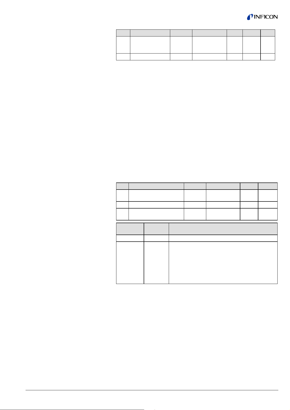
3.3.4 Atmosphere Sensor
Transducer Block (Piezo
Sensor) / SLOT 1 /
Instance 4
ID Name Structure Data type Bytes Access Store
14 Atmosphere
gauge Block State
Command
101 Block Type Simple Octet string 4 2_R
REC 2 1_W
2_W
3.3.4.1 Block Type
3.3.4.2 Atmosphere Sensor Block
State Command
The Block Type ID has the value: "01 00 00 00" (octet string).
This service is used for activating the adjustment of the Piezo sensor to the
Capacitance diaphragm sensor via Profibus.
The atmosphere pressure sensor can be adjusted to the internal (vacuum chamber) Capacitance diaphragm sensor.
If you want to adjust the atmosphere pressure sensor to the Capacitance
diaphragm sensor, proceed as follows:
n Vent the vacuum system to atmospheric pressure
o Send the "Release User ATM adjust" command
p Perform the "User ATM adjust command" as specified below.
After this procedure, the atmosphere pressure sensor will give the same pressure
value as the Capacitance diaphragm sensor at atmospheric pressure.
ID Name Structure Data type Bytes Access
14 Atmosphere gauge Block
State Command
Transition Command Simple Unsigned8 1
Transition Command
Target Value
Record
Simple Usingned8 1
→ below
2 1/2_W
State
Command
0 Inactive No action
128 Adjust
Name Description
Piezo /
CDG
This service is used for activating the adjustment of
the piezo sensor to the Capacitance diaphragm sensor.
The Transition Command Target Value can have the
following values:
0
⇒ executes a User ATM adjust
1
⇒ releases User ATM adjust
tira41e1 (2005-06) BCG450SPv1.cp 41
Page 42
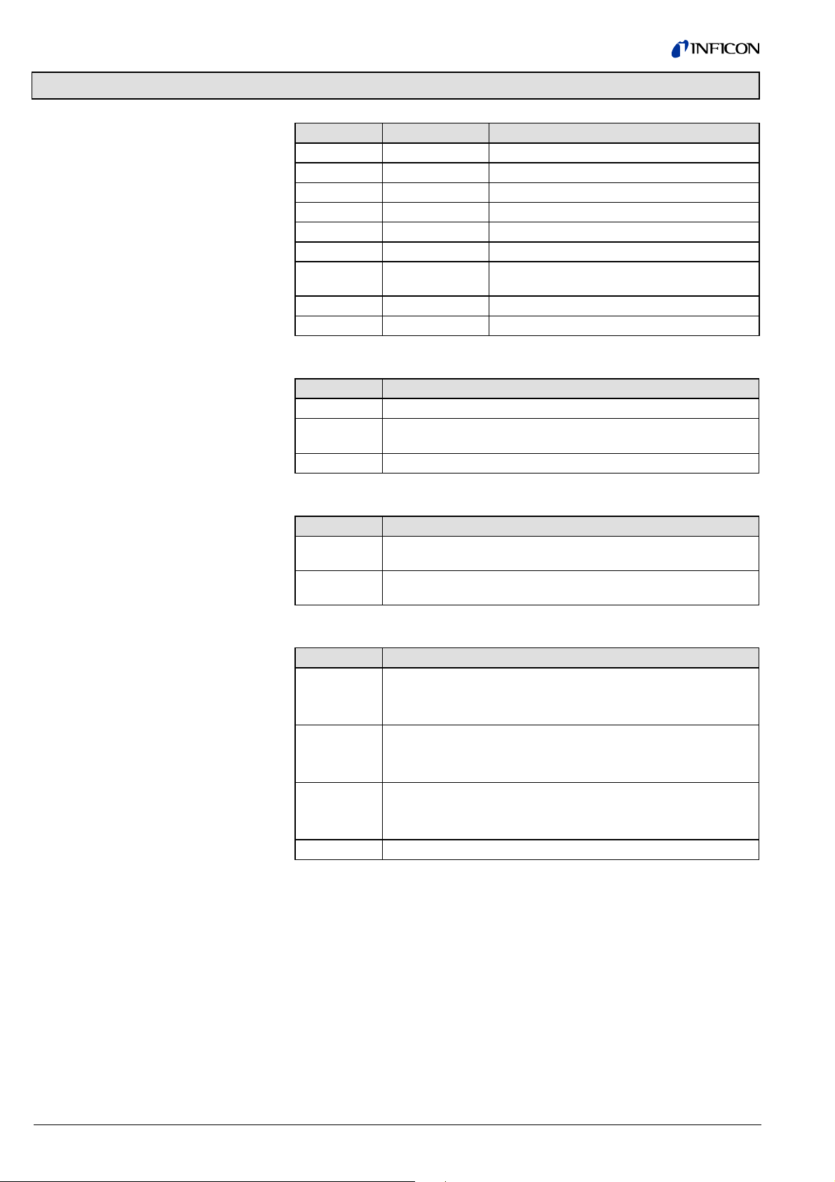
Appendix A: Definitions
Data types
Definitions
Store characteristics
Abbreviation Range Data type
INT8 -27 … (27 - 1) Integer 1 byte
INT16 -215 … (2
INT32 -231 … (231 - 1) Integer 4 byte
UINT8 0 … (28 - 1) Unsigned integer 1 byte
UINT16 0 … (216 - 1) Unsigned integer 2 byte
UINT32 0 … (231 - 1) Unsigned integer 4 byte
FLOAT
VSTRING(n) ISO 646 and ISO 2375
OSTRING(n) Octet string
Term Meaning
Byte Number of bytes used by a data structure (integer value)
Store This parameter defines whether the values are stored in non-
Default Manufacturer-defined value
Abbreviation Meaning
V "Volatile": Value is not saved to the RAM or EEPROM and is lost
N "Nonvolatile": Value is saved to the RAM or EEPROM and is not
±3.402×10
volatile memory (
in the event of a power failure
lost in the event of a power failure
15
- 1) Integer 2 byte
38
Floating Point, IEEE 754 Short Real Number,
4 byte
→ store characteristics)
Data access
Abbreviation Meaning
1_R/W Acyclically readable and writeable by a Master Class 1
2_R/W Acyclically readable and writeable by a Master Class 2
1/2_R/W Acyclically readable and writeable by a Master Class 1 and 2
1_R Acyclically readable by a master Class 1
2_R Acyclically readable by a master Class 2
1/2_R Acyclically readable by a master Class 1 and 2
1_W Acyclically writeable by a master Class 1
2_W Acyclically writeable by a master Class 2
1/2_W Acyclically writeable by a master Class 1 and 2
0_XI Cyclic output data with master Class 1
42 tira41e1 (2005-06) BCG450SPv1.cp
Page 43

Excerpts from:
"PROFIBUS Profile for SEMI"
(→ 4)
The following table explains terms used in connection with the Profibus.
Term Meaning
Alert Elements Alert Elements are used to communicate notification mes-
sages from slave to master when warnings, alarms or
events are detected.
Application A software functional unit consisting of an interconnected
aggregation of function blocks, events and objects, which
may be distributed and which may have interfaces with
other applications.
Characteristic An characteristic is a property or characteristic of an entity.
(Au) In block applications a block interface is defined by
input/output parameters. These parameters have characteristics called parameter characteristics. Examples are
access rights and identification names.
(IT) The UML defines characteristics as a feature within a
classifier that describes a range of values that instances of
the classifier may hold. It is a property of a class instance
(object).
Block
(Block Instance)
A logical processing unit of software comprising an individual, named copy of the block and associated parameters
specified by a block type, which persists from one invocation of the block to the next. Concept similar to the class/
object approach, but well suited to the automation requirements.
Class (IT) A class represents a template for several objects and
describes how these objects are structured internally. Objects of the same class have the same definition both for
their operations and for their information structures.
Configuration (of a
system/device)
A step in system design: selecting functional units, assigning their locations and identifiers and defining their interconnections.
Data Structure An aggregate whose elements need not be of the same
data type, and each of them is uniquely referenced by an
offset identifier.
Data Type A data item with certain characteristics and permissible
operations on that data, e.g. INT8.
Device A physical entity capable of performing one or more speci-
fied functions in a particular context and delimited by its
interfaces.
Direction of Data Input data are transmitted from the device to the bus. Out-
put data are transmitted from the bus to the device.
Direction of Flow A positive set point causes a flow from P to A.
Entity A particular thing, such as a person, place, process, object,
concept, association or event.
Function (1) A specific purpose of an entity.
(2) One of a group of actions performed by an entity.
Function Block A named block consisting of one or more input, output and
contained parameters. Function blocks represent the basic
automation functions performed by an application which is
as independent as possible from the specifics of I/O devices
and the network. Each function block processes input
parameters according to a specified algorithm and an inter-
nal set of contained parameters. They produce output pa-
rameters that are available for use within the same function
block application or by other function block applications.
tira41e1 (2005-06) BCG450SPv1.cp 43
Page 44

Excerpts from:
"PROFIBUS Profile for SEMI"
(cont.)
Term Meaning
Function Block
Application
Application of an automation system performed by a Device
Block, Function Block, Transducer Block and accompanied
elements.
Instance A set of data related to an invocation of a function block or a
class.
Internal Resolution
(ir)
The internal resolution is 16383 (3FFF
-16384 (C000
) for -100% of the range.
hex
) for 100% and
hex
Mode Determines the block operating mode and available modes
for a block instance.
Object (IT) A software entity having identity, attributes and behav-
ior.
Parameter A variable that is given a constant value for a specified
application and that may denote the application.
Device Block A Device Block is a named block. Hardware specific pa-
rameters of a field device, which are associated with a resource, are made visible through the Device Block. Similar
to transducer blocks, they insulate function blocks from the
physical hardware by a set of implementation independent
hardware parameters.
Record A set of data items of different data types treated as a unit.
Resource A resource is considered to be a logical subdivision within
the software (and possibly hardware) structure of a device.
Resources have independent control of their operation. The
definition of a resource may be modified without affecting
other resources within a device. A resource accepts and
processes data and/or events from the process and/or
communication interfaces and returns data and/or events to
the process and/or communication interfaces, as specified
by the applications utilizing the resource. An interoperable
network view of applications is provided through device re-
sources. Each resource specifies the network visible as-
pects of one or more local applications (or parts of distri-
buted applications).
Simple Variable A single variable which is characterized by a defined Data
Type.
Substitute Value In case an optional parameter has not been implemented,
the device behaves according to the substitute value for this
parameter.
Transducer Block Transducer Block is a named block. Transducer blocks
insulate function blocks from the specifics of I/O devices,
such as sensors, actuators, and switches. Transducer
blocks control access to I/O devices through a device in-
dependent interface defined for use by function blocks.
Transducer blocks also perform functions, such as cali-
bration and linearization, on I/O data to convert it to a de-
vice independent representation. Their interface to function
blocks is defined as one or more implementation independ-
ent I/O channels.
Variable A software entity that may assume any one of a set of val-
ues. The values of a variable are usually restricted to a
certain data type.
44 tira41e1 (2005-06) BCG450SPv1.cp
Page 45

Appendix B: Block Type
Currently defined Block Type IDs
Block Name Block Type ID
Device Block 1
Sensor Analog Input Function Block 2
One of N Channel Sensor Analog Input Function Block 3
Multi Channel Sensor Analog Input Function Block 4
Discrete Input Function Block 5
Actuation Analog Output Function Block 6
Discrete Output Function Block 7
Analog Output Function Block 8
Single Stage Controller Function Block 9
Gas Calibration Transducer Block 10
Flow Transducer Block 11
Sensor Analog Input Ambient Temperature Transducer Block 12
Heat Transfer Vacuum Gauge...
Diaphragm Gauge
3)
1)
13
14
Cold Cathode Ion Gauge 15
Hot Cathode Ion Gauge
2)
16
Trip Point Function Block 17
Reserved 18 … 28 - 1
Manufacturer-specific 28 … 216 - 1
1)
Pirani measuring system
2)
BA measuring system
3)
CDG measuring system
tira41e1 (2005-06) BCG450SPv1.cp 45
Page 46

Appendix C: Electrical Connections
Technical data of BCG450 gauges → [1], [2], [3].
Sensor cable connection
Threshold values
SP A
SP B
Degas
Measuring
signal
( )
2)
2)
SP A
SP B
-
+
42 k
-
1)
3
6
1
4
9
11
13
14
7
2
12
Ω
8
10
5
15
Degas
-
1.25 AT
Ident.
24V
-
-
Common (power GND 24V supply)
Ground (housing, vacuum connection)
9
15
1
D-Sub,15 pins,
female,
soldering side
8
Electrical connection
Pin 1 Relay switching function A, n.o. contact
2)
Pin 2 Measuring signal output 0 … +10.13 V
Pin 3 Threshold (setpoint) A
Pin 4 Relay switching function A, com contact
1)
2)
0 … +10 V
Pin 5 Supply common 0 V
Pin 6 Threshold (setpoint) B
1)
0 … +10 V
Pin 7 Degas on, active high 0 V/+24 V
Pin 8 Supply +24 V
Pin 9 Relay switching function B, n.o. contact
2)
Pin 10 Gauge identification
Pin 11 Relay switching function B, com contact
2)
Pin 12 Measuring signal common
Pin 13 Do not connect
Pin 14 Do not connect
Pin 15 Do not connect
1)
Do not connect pin 3 and pin 6 for normal operation of the gauge. These pins
are reserved for adjustment of the setpoint potentiometers.
2)
Relay assignement can be reprogrammed (→ 34).
46 tira41e1 (2005-06) BCG450SPv1.cp
Page 47

Profibus connection
1 5
6 9
Pin 1 not connected
Pin 2 not connected
Pin 3 RxD/TxD-P
Pin 4 CNTR-P
Pin 5 DGND
Pin 6 VP
Pin 7 not connected
Pin 8 RxD/TxD-N
Pin 9 not connected
1)
Only to be connected if an optical link module is used.
2)
Only required as line termination for devices at both ends of bus cable
→ [4]).
(
D-Sub, 9 pins, male
soldering side
1)
2)
2)
tira41e1 (2005-06) BCG450SPv1.cp 47
Page 48

Appendix D: Literature
[1] www.inficon.com
Instruction Sheet
TripleGauge™,
Bayard-Alpert Pirani Capacitance Diaphragm Gauge
BCG450, BCG450-SD, BCG450-SP
tima40e1
INFICON AG, LI–9496 Balzers, Liechtenstein
[2] www.inficon.com
Instruction Sheet
TripleGauge™,
Bayard-Alpert Pirani Capacitance Diaphragm Gauge
BCG450-SD, BCG450-SP
tima41e1
INFICON AG, LI–9496 Balzers, Liechtenstein
[3] www.inficon.com
Operating Manual
Bayard-Alpert Pirani Capacitance Diaphragm Gauge
BCG450, BCG450-SD, BCG450-SP
tina40e1
INFICON AG, LI–9496 Balzers, Liechtenstein
[4] www.profibus.com
(Profibus user organization)
[5] European Standard for Profibus EN 50170
48 tira41e1 (2005-06) BCG450SPv1.cp
Page 49

Notes
tira41e1 (2005-06) BCG450SPv1.cp 49
Page 50

Notes
50 tira41e1 (2005-06) BCG450SPv1.cp
Page 51

Notes
tira41e1 (2005-06) BCG450SPv1.cp 51
Page 52

LI–9496 Balzers
Liechtenstein
Tel +423 / 388 3111
Fax +423 / 388 3700
Original: German tira41d1 (2005-06) reachus@inficon.com
t i ra41e1
www.inficon.com
 Loading...