

Page 1

Communication Protocol
DeviceNet™
Interface for Bayard-Alpert Capacitance Diaphragm Gauge
BCG450-SD
tira40e1 (2005-04) 1
Page 2

Intended Use
of this Document
This Communication protocol contains instructions for operating the vacuum gauges BCG450-SD (featuring DeviceNet interfaces) as slaves together with a
DeviceNet master.
This manual describes the functionality of DeviceNet for programming
purposes. For more information refer to the "DeviceNet specifications" of
the Open DeviceNet Vendor Association (ODVA) (→ [2]) and the corresponding european standard (→ [3]).
For specifications and operation instructions of the vacuum gauges refer
to the appropriate documents:
BCG450-SD → [1], [4], [5], [6]
DeviceNet Interface
Abbreviations
The following description of the DeviceNet Interface is compliant to the DeviceNet
specification of the Open DeviceNet Vendor Association.
This manual describes the functionality of a DeviceNet Group 2 Only Slave and
supports Explicit Messaging and the I/O Polling.
We reserve the right to make technical changes without prior notice.
Abbr. Meaning
NV Nonvolatile; attribute value is maintained through power cycles
V Volatile
INT Integer value (Range –32767 … 32768)
UINT Unsigned integer value (Range 0 … 65635)
USINT Unsigned character value (Range 0 … 255)
FLOAT Floating point value (Range according to IEEE 754)
XX
XX
XX
Hexadecimal number (Radix = 16)
h
Decimal number (Radix = 10)
d
Binary number (Radix = 2)
b
Trademarks
2 tira40e1 (2005-04) BCG450SDv1.cp
DeviceNet™ Open DeviceNet Vendor Association Inc.
Page 3

Contents
Intended Use of this Document 2
DeviceNet Interface 2
Abbreviations 2
Trademarks 2
1 Start-Up of the Slave 4
1.1 Power Supply Requirements 4
1.2 Front View of the BCG450-SD 4
1.3 Connectors on the Device 5
1.4 Side View of the BCG450-SD 6
1.5 Indicators and Switches 6
1.5.1 Module Status LED 6
1.5.2 Network Status LED 7
1.5.3 Node Address Switch 7
1.5.4 Data Rate Switch 7
1.5.5 Setpoint 7
2 Object Structure 8
2.1 Connection Object 8
2.1.1 Vendor-Specific Object Extension on Instance 2 Poll Connection 8
2.2 Identity Object 9
2.2.1 Class Attributes 9
2.2.2 Instance Attributes 9
2.3 S-Device Supervisor Object 9
2.3.1 Class Attributes 9
2.3.2 Instance Attributes 10
2.3.2.1 Semantics 11
2.3.3 S-Device Supervisor Object States 15
2.3.4 S-Device Supervisor Common Services 15
2.3.5 S-Device Supervisor Object Specific Services 16
2.4 S-Analog Sensor Object 16
2.4.1 Class Attributes 16
2.4.2 Instance Attributes 17
2.4.2.1 Instance Attributes of Instance 1 / Pirani Instance 17
2.4.2.2 Semantics of S-Analog Sensor Instance 1 18
2.4.2.3 Instance Attributes of Instance 2 / Hot Cathode Ion Gauge 20
2.4.2.4 Semantics of S-Analog Sensor Instance 2 21
2.4.2.5 Instance Attributes of Instance 3 / Capacitance Diaphragm Gauge 23
2.4.2.6 Semantics of S-Analog Sensor Instance 3 24
2.4.2.7 Object-Specific Services on Instance 3 /
Capacitance Diaphragm Gauge 25
2.4.2.8 Instance Attributes of Instance 21 / Setpoint A
(Instance 22 / Setpoint B) 26
2.4.3 Common Services 29
2.4.4 Object-Specific Services on Instance 2 / Hot Cathode Ion Gauge 29
2.4.4.1 SET DEGAS STATE 29
2.4.4.2 SET EMISSION STATE 29
2.4.4.3 Emission Control Mode 30
2.4.5 Behavior 30
3 I/O Assembly Object 31
3.1 I/O Assembly Instances 31
3.2 I/O Assembly Object Instance Data Attribute Format 32
Appendix 33
A: Range of Values 33
B: Specific Codes 33
C: Conversion of a Floating Number According to IEEE 754 33
D: Typical Start-Up Procedure 34
E: Literature 37
For cross-references within this document, the symbol (→ XY) is used, for crossreferences to further documents listed under literature, the symbol (→ [Z]).
tira40e1 (2005-04) BCG450SDv1.cp 3
Page 4
1 Start-Up of the Slave
1.1 Power Supply
Requirements
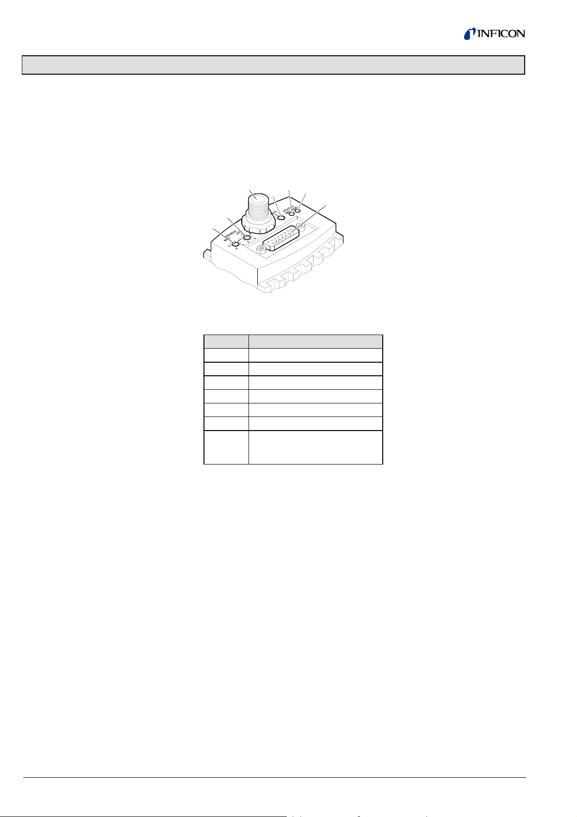
1.2 Front View of the
BCG450-SD
The BCG450-SD has to be powered with two voltages:
1.) 24 Volt DC, 20 W at the 15 pole Sub-D connector for the gauge itself;
2.) 24 Volt DC nominal, <2 W range +11 … +25 V) at the DeviceNet micro style
connector for the DeviceNet transceiver.
3
2
1
Position Function
1 Address Switch × 10, decimal
2 Address Switch × 1, decimal
3 DeviceNet connector
4 Data Rate Switch
5 Network Status LED
6 Module Status LED
7 "Sensor cable" connector
(Power, analog I/O, RS232C I/O
and Relay contacts)
5
4
6
7
4 tira40e1 (2005-04) BCG450SDv1.cp
Page 5
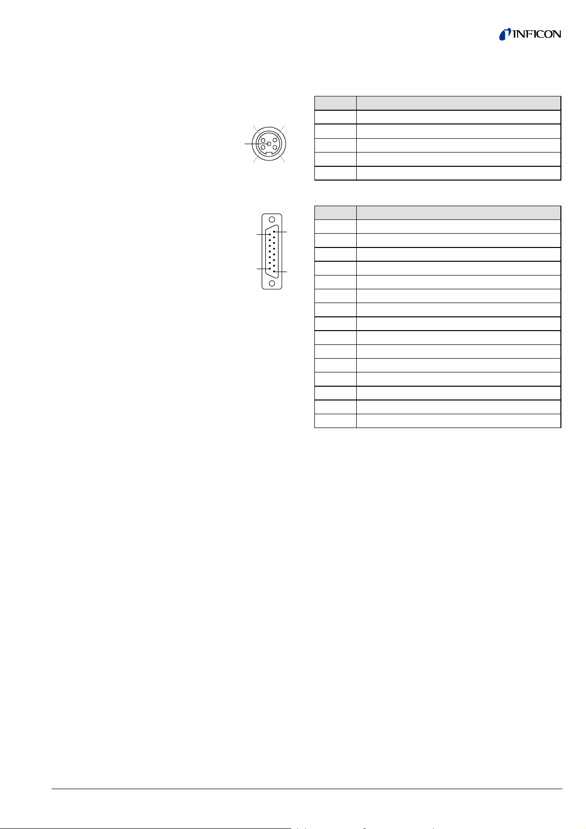
1.3 Connectors on the
Device
The BCG450-SD uses a "Sealed Micro-Style Connector" for the DeviceNet connection. The DeviceNet part of the gauge is powered via the DeviceNet connector.
Pin Assignment of the Sealed
Micro-Style Connector
Pin Assignment of the 15 pin
D-Sub connector
Pin Function
4
5
1
3
2
1 Drain
2
V+ nominal +24 V (range +11 … +25 V)
3V–
4 CAN_H
5 CAN_L
Pin Function
1)
15
8
1 Relay Setpoint A, n.o. contact
2 Measuring signal output (0 … +10.13 V)
3 Threshold Setpoint A, output (0 … +10 V)
9
1
4 Relay Setpoint A, common contact
5 Supply sensor electronics common
1)
6 Threshold Setpoint B output (0 … +10 V)
7 Degas on, active high
8 Supply sensor electronics +24 Volt
9 Relay Setpoint B, n.o. contact
1)
10 Gauge identification
11 Relay Setpoint B, common contact
1)
12 Signal common GND
13 do not connect
14 do not connect
15 do not connect
1)
Type of setpoint function assigned to relays is programmable (→ 26).
tira40e1 (2005-04) BCG450SDv1.cp 5
Page 6
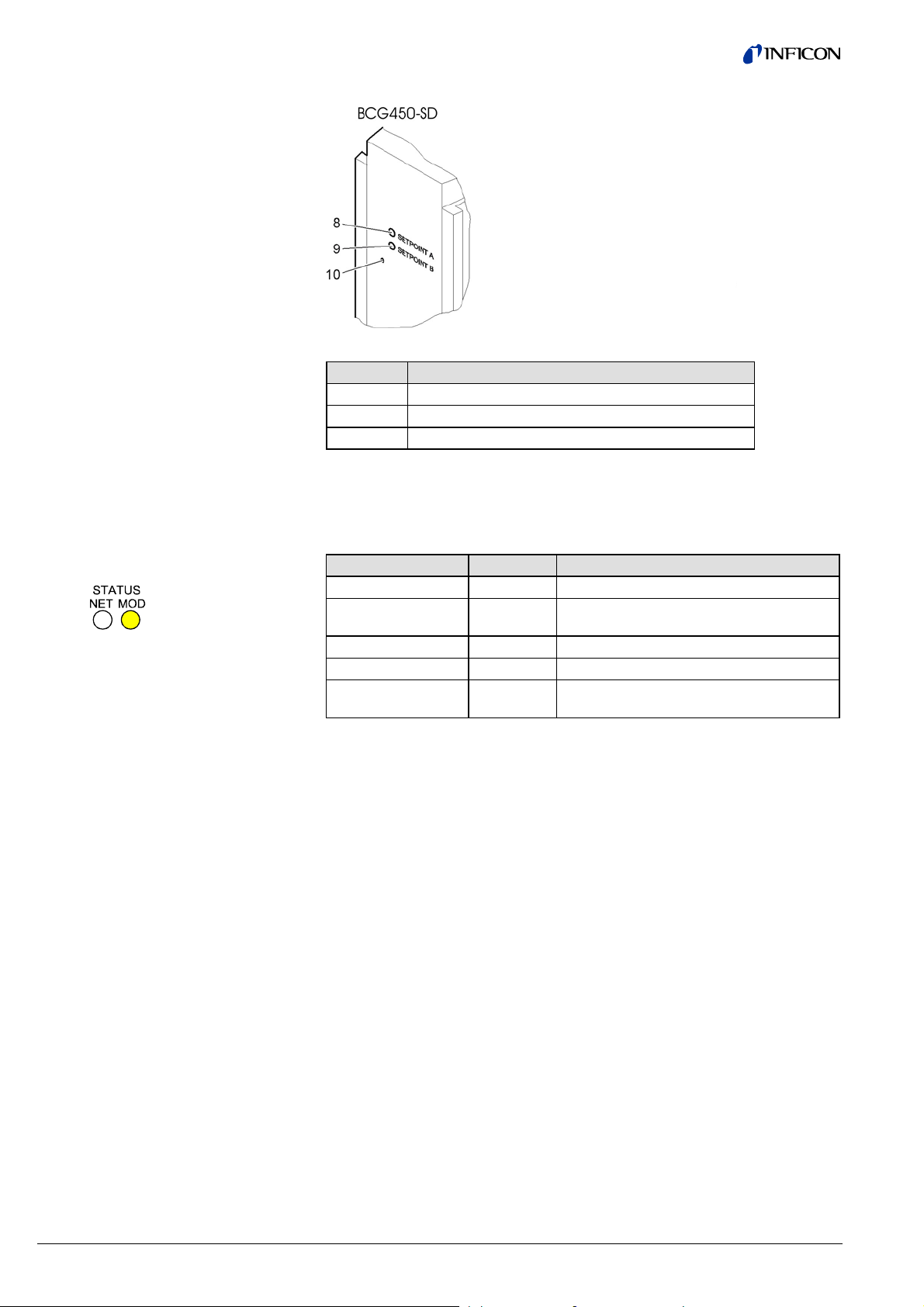
1.4 Side View of the
BCG450-SD
1.5 Indicators and Switches
Position Function
8 Potentiometer for Setpoint A threshold
9 Potentiometer for Setpoint B threshold
10 Special Calibration service / do not use
1.5.1 Module Status LED
Device State LED State Description
Power Off dark No power applied to device
Device Self-Test flashing
green/red
Device Operational green Device is operating normally.
Unrecoverable Fault red Device has detected an unrecoverable fault
Recoverable Fault flashing red Device has detected a recoverable fault,
Device is in self-test
e.g. missing DeviceNet power supply
6 tira40e1 (2005-04) BCG450SDv1.cp
Page 7
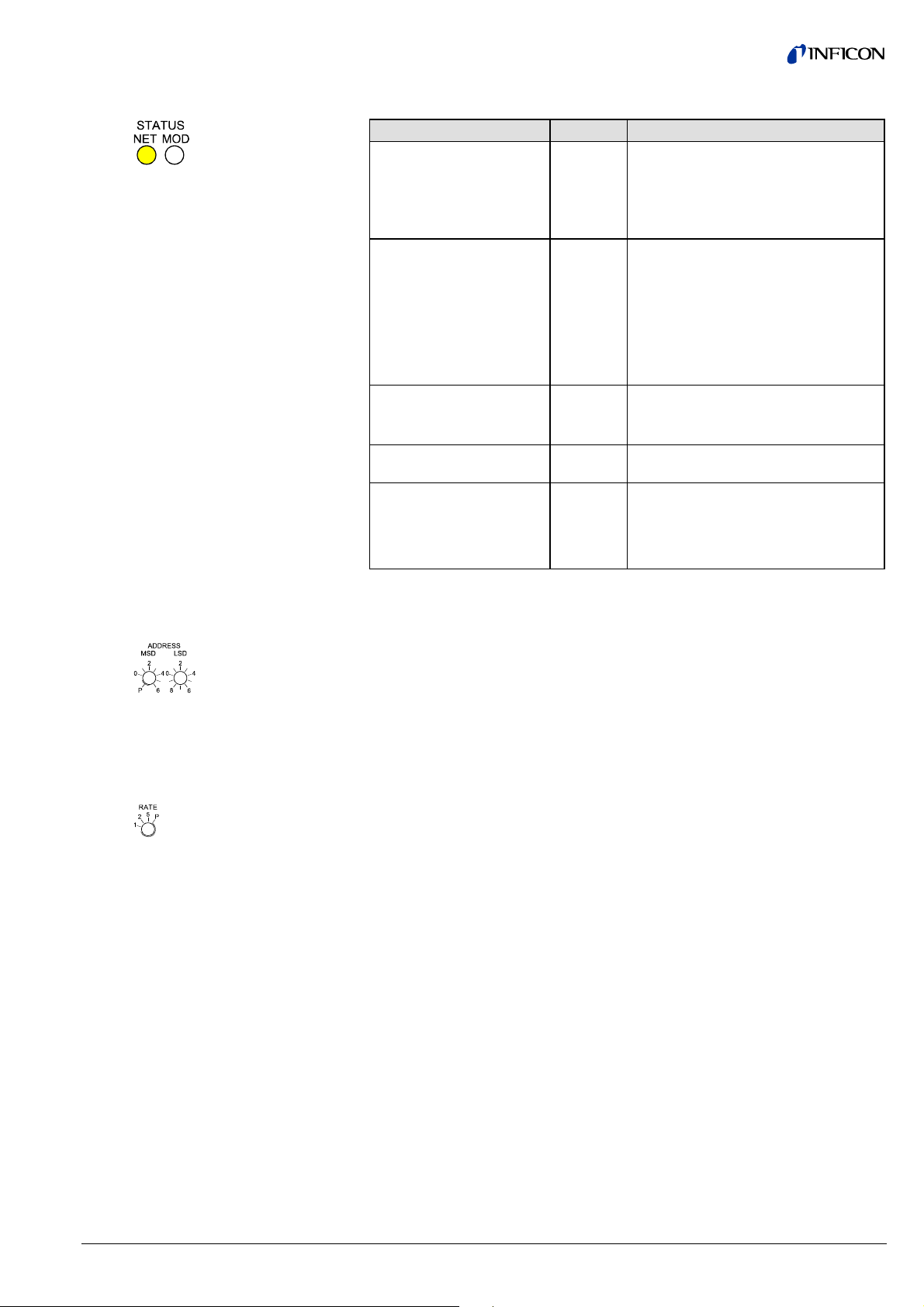
1.5.2 Network Status LED
1.5.3 Node Address Switch
1.5.4 Data Rate Switch
1.5.5 Setpoint
The network status LED indicates the status of the DeviceNet communication link.
State LED state To indicate
Not Powered/not online dark Device is not online.
• The device has not completed the
Duplicate MAC_ID test yet.
• The device may not be powered,
look at Module Status LED.
Online, not connected flashing
green
Device is online but has no connections
in the established state.
• The device has passed the
Dup_MAC_ID test, is online, but
has no established connections to
other nodes.
• The device is not allocated to a
master.
Link OK online, connected green The device is online and has connec-
tions in the established state.
• The device is allocated to a master.
Connection time out flashing
red
One or more I/O Connections are in the
timed out state.
Critical link failure red Failed communication device. The
device has detected an error that has
rendered it incapable of communicating
on the network (Duplicate MAC ID, or
Bus–off).
During device initialization, the node address switches are read by the device firmware. If the switches specify a valid DeviceNet MAC ID, i.e. a value from 0 … 63,
this value is used as the device MAC ID. If the specified MAC ID differs from the
value stored in the device’s non-volatile RAM (NVRAM), the new MAC ID will be
saved in NVRAM. If the switches specify an invalid DeviceNet MAC ID, i.e. a value
greater than 63, the current value stored in the device’s NVRAM is used as the
device MAC ID.
A single, rotary switch is provided for configuring the data rate of the device. The
switch has three valid positions for the DeviceNet data rates, 125, 250, and
500 kBaud, where:
1 125 kBaud
2 250 kBaud
5 500 kBaud
All remaining switch positions specify software selection of the data rate.
The device has two setpoint relays 1) (Setpoint A and Setpoint B). The setpoints of
these relays are adjustable only by two potentiometers (marked SETPOINT A and
SETPOINT B).
The relay contacts are available at the 15-pin D-Sub connector.
1)
Type of setpoint function assigned to relays is programmable (→ 26).
tira40e1 (2005-04) BCG450SDv1.cp 7
Page 8

2 Object Structure
2.1 Connection Object
2.1.1 Vendor-Specific Object
Extension on Instance 2
Poll Connection
Class Code 05h = 05
The connection class allocates and manages the internal resources associated
with both I/O and explicit messaging connections. The specific instance generated
by the connection class is referred to as a connection instance or a connection
object.
The following Instances of the connection object are supported:
• Instance 1: Explicit Messaging
• Instance 2: I/O-Polling
Please refer to the DeviceNet specification for further information.
For the selection of the active input assembly the following vendor specific attribute
can be used.
Vendor specific extension:
d
AttributeIDRequirement in
Implementation
100 Optional Get/Set NV Poll Produce
Access
Rule
NV/V Name DeviceNet
Assembly
Instance
This vendor-specific attribute facilitates the configuration of the data assembly, sent
by the BCG450-SD to the DeviceNet Master as Poll response. It offers the possibility to select a (predefined) data assembly via a configuration tool + EDS file
(→ [1]). Attribute 100 allows the user to configure the Poll I/O Data Assembly
via EDS even when the Poll Connection of the BCG450-SD is in the established
state. The Assembly Number is stored non volatile. Modifications of the Poll
Produce Assembly Instance will take effect only after a reset of the BCG450-SD.
Thus, definition of the BCG450-SD data assembly can be done in two ways:
1) Standard methode (without using attribute 100):
The DeviceNet Master configures the "Produced Connection Path" Attribute of
the Poll connection (Connection Instance 2) when establishing communication
to the BCG450-SD. This requires a master to support expanded explicit messaging capabilities.
2) Directly setting Attribute 100 e.g. by a configuration tool
(e.g. RS Networks) + Device Reset.
Description of Attribute Semantics
Data Type
USINT Contains the Instance num-
ber of the assembly used by
this connection to send data
1, 2, 4, 5, 8, 9, 10, 12, 13
8 tira40e1 (2005-04) BCG450SDv1.cp
Page 9

2.2 Identity Object
Class Code 01h = 01
d
2.2.1 Class Attributes
Attribute ID Access Rule Name DeviceNet
1 Get Revision UINT Revision of this object.
2 Get Max Instance UINT Maximum instance number of
This object provides identification of and general information about the device.
Description of Attribute Semantics of Values
Data Type
The current value assigned to this
Note: All class definitions are
required to include this class
attribute.
an object currently created in
this class level of the device.
attribute is one (01). If updates that
require an increase in this value are
made, then the value of this attribute
increases by one.
The largest Instance number of a
created object at this class hierarchy
level.
2.2.2 Instance Attributes
Attribute ID Access Rule NV/VName DeviceNet Data Type Description of Attribute
1 Get NV Vendor ID UINT 79 02 Manufacturer identification
Value: 633 (INFICON)
2 Get NV Device Type UINT 1Ch = Vacuum pressure gauge
3 Get NV Product Code UINT 13
4 Get NV Revision STRUCT
5 Get NV Status WORD
6 Get NV Serial Number UDINT
7 Get NV Product Name SHORT STRING BCG450-SD
Services
2.3 S-Device Supervisor
Service Code Name Description
5 (05h) Reset 0 = last installation,
1 = default installation
14 (0Eh) Get_Attribute_Single
Class Code 30h = 48
d
Object
2.3.1 Class Attributes
Attribute ID Access
Rule
1 Get Revision UINT Revision of this object The current value assigned to this at-
2 Get Max
Name DeviceNet
Data Type
UINT Maximum instance number of an
Instance
Description of Attribute Semantics of Values
tribute is one (01). If updates that require
an increase in this value are made, then
the value of this attribute increases by
one.
The largest Instance number of a creobject currently created in this
class level of the device.
ated object at this class hierarchy level.
tira40e1 (2005-04) BCG450SDv1.cp 9
Page 10

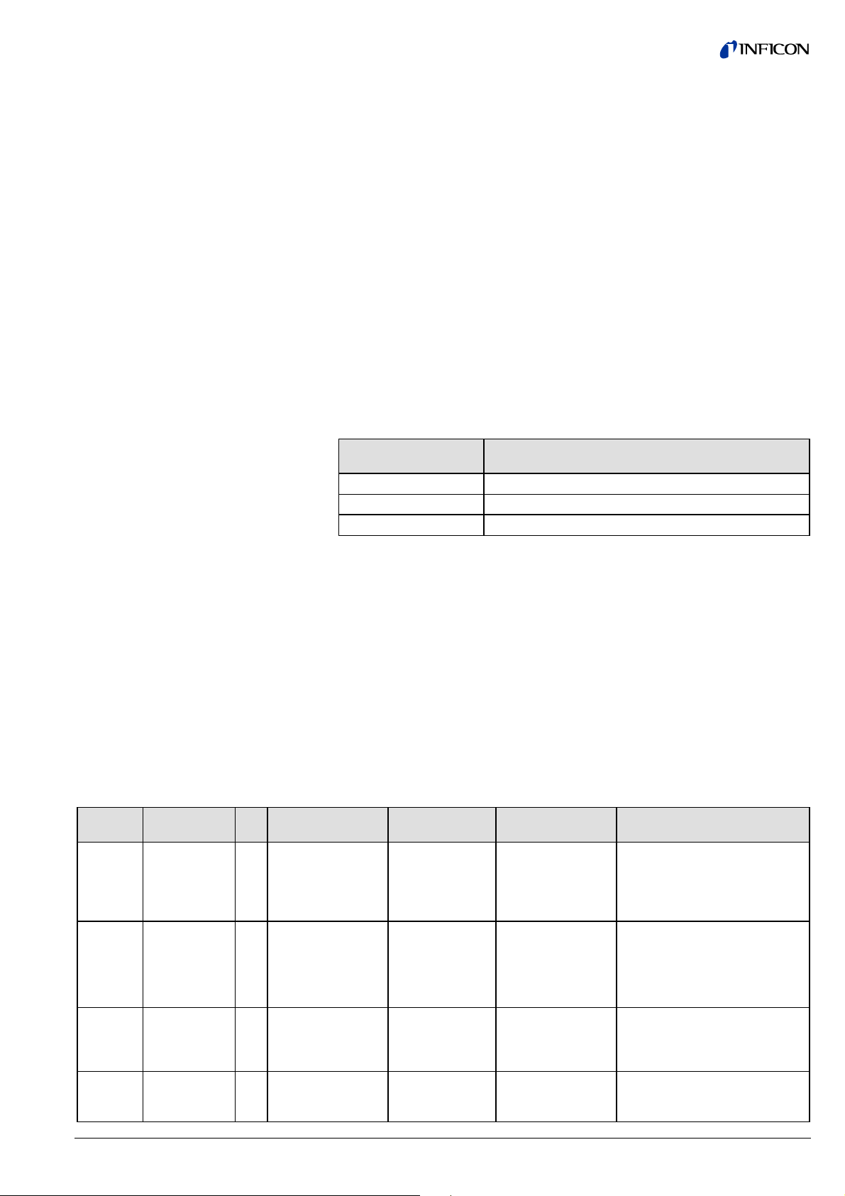
2.3.2 Instance Attributes
Attribute ID Access Rule NV/VName DeviceNet Data Type Description of Attribute
3 Get NV DeviceType SHORT STRING ASCII Text, "CG" combination gauge
4 Get NV SEMI Standard
Revision Level
5 Get NV Manufacturer’s Name SHORT STRING "INFICON"
6 Get NV Manufacturer’s Model
Number
7 Get NV Software Revision
Level
8 Get NV Hardware Revision
Level
9 Get NV Manufacturer’s Serial
Number
10 Get NV Device Configuration SHORT STRING Depending on device configuration
11 Get V Device Status USINT
12 Get V Exception Status BYTE
13 Get V
Exception Detail
Alarm
Common
Exception Detail
Size 2 USINT Number of common detail bytes
Detail 0 ARRAY of:
Detail 1 BYTE
Device Exception
Detail
Size 6 USINT Number of device detail bytes
Detail 0 ARRAY of: S-Analog Sensor Instance 3
Detail 1 BYTE S-Analog Sensor Instance 3
Detail 2 S-Analog Sensor Instance 1
Detail 3 S-Analog Sensor Instance 1
Detail 4 S-Analog Sensor Instance 2
Detail 5 S-Analog Sensor Instance 2
Manufacturer
Exception Detail
Size 1 USINT Number of Manufacturer detail bytes
Detail 0 ARRAY of: Serial communication alarm
SHORT STRING Specifies the revision level of the SEMI
S/A network standard to which the device
complies (for example "E54-0997").
SHORT STRING for example: BCG450-SD
SHORT STRING ASCII Text, for example "xxxyyy"
xxx version of the measuring print
yyy version of the DeviceNet print
SHORT STRING ASCII text, for example "1.001"
SHORT STRING ASCII text
(→ Appendix B)
→ "Semantics" section below.
→ "Semantics" section below.
STRUCT of: A structure of three structures containing
a bit mapped representation of the alarm
detail
STRUCT of:
→ "Semantics" section below.
→ "Semantics" section below.
STRUCT of:
(Capacitance Diaphragm Gauge)
Sensor alarm byte 0
(Capacitance Diaphragm Gauge)
Sensor alarm byte 1
(Pirani) Sensor Alarm byte 0
(Pirani) Sensor alarm byte 1
(Hot cathode) Sensor Alarm byte 0
(Hot cathode) Sensor alarm byte 1
STRUCT of:
10 tira40e1 (2005-04) BCG450SDv1.cp
Page 11

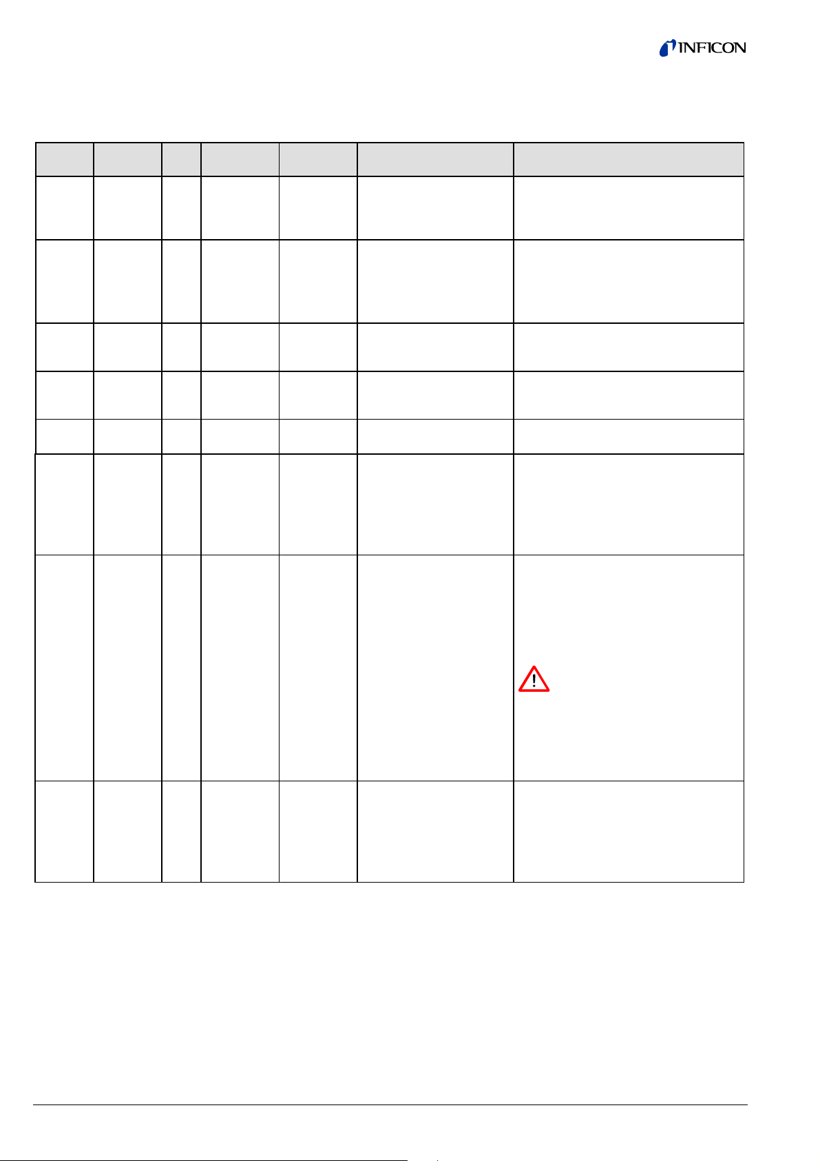
Attribute ID Access Rule NV/VName DeviceNet Data Type Description of Attribute
14 Get V
Exception Detail
STRUCT of: A structure of three structures containing
Warning
Common Exception
STRUCT of:
Detail
Size 2 USINT Number of Common Detail Bytes
Detail 0 ARRAY of:
Detail 1 BYTE
Device Exception
STRUCT of:
Detail
Size 7 USINT Number of Device Detail Bytes
Detail 0 ARRAY of: S-Analog Sensor
Detail 1 ARRAY of: S-Analog Sensor Instance 3
Detail 2 BYTE S-Analog Sensor Instance 3
Detail 3 BYTE
Detail 4
Detail 5 S-Analog Sensor Instance 2
Detail 6 S-Analog Sensor Instance 2
Manufacturer
STRUCT of:
Exception Detail
Size 1 USINT Number of Manufacturer Detail Bytes
Detail 0 Byte serial common warning
15 Set NV Alarm Enable BOOL
16 Set NV Warning Enable BOOL
a bit mapped representation of the
warning detail
→ "Semantics" section below.
→ "Semantics" section below.
Class Level Status Extension
(Capacitance Diaphragm Gauge)
Sensor Warning Byte 0
(Capacitance Diaphragm Gauge)
Sensor Warning Byte 1
S-Analog Sensor Instance 1 (Pirani)
Sensor Warning Byte 0
S-Analog Sensor Instance 1 (Pirani)
Sensor Warning Byte 1
(hot cathode) Sensor Warning Byte 0
(hot cathode) Sensor Warning Byte 1
→ "Semantics" section below.
→ "Semantics" section below.
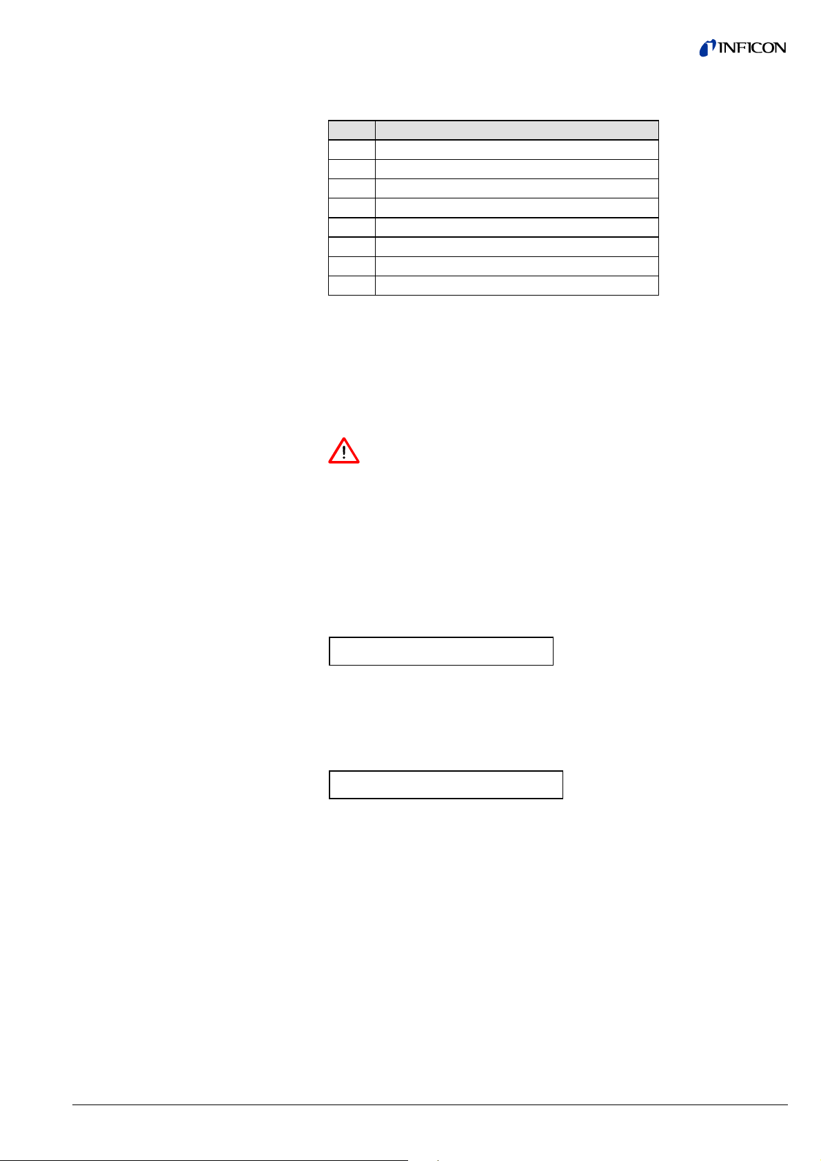
2.3.2.1 Semantics
Device Status
tira40e1 (2005-04) BCG450SDv1.cp 11
This attribute represents the current state of the device. Its value changes as the
state of the device changes. The following values are defined:
Attribute Value State
0 Undefined
1 Self Testing
2 Idle
3 Self-Test Exception
4 Executing
5 Abort
6 Critical Fault
In case of a Self-Test Exception restart the device with a reset out of the box
(Identity Object Class 1, Instance 1, Service 5, Service target value: 1).
Page 12

Exception Status
A single byte attribute whose value indicates the status of the alarms and warnings
for the device. The device supports the Expanded Mode.
For the Expanded Mode, bit seven of Exception Status attribute is set to one;
exceptions are reported through the communication of this Exception Status attribute, formatted as specified in the table below. In addition, the Exception Detail
attributes are supported. The Exception Status bits are determined by a logical
”OR” of the related Exception Detail bits, as indicated.
Exception Status Bit Map
Exception Detail Alarm and
Exception Detail Warning
Bit Function
0 ALARM/device-common
(The alarm or warning is not specific to the device type or device type
manufacturer.)
1 ALARM/device-specific
2 ALARM/manufacturer-specific
3 reserved, set to 0
4 WARNING/device-common
5 WARNING/device-specific
6 WARNING/manufacturer-specific
7
1 Expanded Method
The formats of these two attributes are identical. Therefore, they are described
together:
Attributes that relate the detailed status of the alarms or warnings associated with
the device. Each attribute is a structure containing three members; these three
members, respectively relate the detailed status of exceptions that are common
(i.e., not device-specific), device-specific but not manufacturer-specific, and manufacturer-specific. The common and device-specific detail are defined below. A
manufacturer-specific detail has a length of 1 byte. A SIZE value of one indicates
that one byte detail is defined for the associated exception detail structure.
Each of the three structure members is defined as a structure containing an ordered list (i.e., array) of bytes of length SIZE, and an unsigned integer whose value
is SIZE. Each of the bytes in each array has a specific mapping. This mapping is
formatted as 8 bits representing 8 independent conditions, whereas a value of 1
indicates that the condition is set (or present), and a value of 0 indicates that the
condition is cleared (or not present). Note that if a device does not support an
exception detail, the corresponding bit is never set. The bitmaps for alarms and
warnings in the corresponding attributes are structured in parallel so that a condition may have either alarm or warning set depending on severity. If a condition
inherently cannot be both alarm and warning, then the parallel bit position corresponding to the other state will remain "0".
Common Exception Detail
12 tira40e1 (2005-04) BCG450SDv1.cp
This structure relates exception conditions (i.e. alarms or warnings) which are
common to all devices within the Hierarchy of Semiconductor Equipment Devices.
The Detail element of the structure is an ordered list (i.e., array) of bytes of length
[SIZE=2] which is the value of the structure element Size. For each byte in the
Detail field, all bits which are not identified are reserved for future standardization.
Two bytes Common Exception Detail are provided: Common Exception Detail [0]
and Common Exception Detail [1]. The specific exception associated with each of
the bitmaps is given in the table below. The SIZE for this revision is two (2).
Page 13

Common Exception Detail
Attribute Values
Bit Common Exception Detail [0] Common Exception Detail [1]
00 0
10 0
2 EPROM exception 0
3 EEPROM exception power supply input voltage
4 RAM exception 0
5 reserved 0
60 0
70 0
Common Exception Detail
Format Summary
Data Component Bit 7 Bit 6 Bit 5 Bit 4 Bit 3 Bit 2 Bit 1 Bit 0
Common Exception Detail
Size
Common Exception Detail 0
Common Exception Detail 1
00000010
0
0000
0
0
Data
Memory
Nonvolatile
Memory
PS Input
Voltage
Code
Memory
000
00
Device Exception Detail
Manufacturer Exception
Detail
This structure, similar in form to Common Exception Detail, relates exception conditions which are specific to individual devices on the network and are defined in
the following. The Detail element of the structure is an ordered list (i.e. array) of
bytes of length [SIZE = 4 for Alarms and SIZE = 6 for Warning] which is the value
of the structure element size.
This structure, similar in form to Common Exception Detail, relates exception conditions which are specific to the manufacturers of individual devices on the network.
There is one byte manufacturer exception details defined. The Detail element of the
structure is an ordered list (i.e. array) of bytes of length [SIZE = 1] which is the
value of the structure element Size.
tira40e1 (2005-04) BCG450SDv1.cp 13
Page 14

Device Exception Detail
Alarms and Manufacturer
Exception Detail Alarms
Format
Data Component Bit 7 Bit 6 Bit 5 Bit 4 Bit 3 Bit 2 Bit 1 Bit 0
Device Exception Detail
Alarm Size
Device Exception Detail
Alarm 0 Capacitance
Diaphragm Gauge
Device Exception Detail
Alarm 1 Capacitance
Diaphragm Gauge
Device Exception Detail
Alarm 0 Pirani
Device Exception Detail
Alarm 1 Pirani
Device Exception Detail
Alarm 2 Hot cathode
Device Exception Detail
Alarm 3 Hot cathode
Manufacturer Exception
Detail Alarm Size
Manufacturer Exception
Detail Alarm
00000110
0 0 0 0 0 0 0 Diaphragm
0 0 0 0 0 0 Electronics
00000000
000000
00000000
000000
00000001
0 0 0 0 0 0 0 serial comm.
Failure
Electronics
Failure
Electronics
Failure
Failure
0
0
0
Exception Detail Warning
Data Component Bit 7 Bit 6 Bit 5 Bit 4 Bit 3 Bit 2 Bit 1 Bit 0
Device Exception Detail
Warning Size
Device Exception Detail 0
S-Analog Sensor Class
Level Status Extension
Device Exception Detail 1
Sensor Warning Byte 0
Capacitance Diaphragm
Gauge
Device Exception Detail 2
Sensor Warning Byte 1
Capacitance Diaphragm
Gauge
Device Exception Detail 3
Sensor Warning Byte 0
Pirani
Device Exception Detail 4
Sensor Warning Byte 1
Pirani
Device Exception Detail 5
Sensor Warning Byte 0
Hot cathode
Device Exception Detail 6
Sensor Warning Byte 1
Hot cathode
Manufacturer Exception
Detail Warning Size
Manufacturer Exception
Detail Warning
14 tira40e1 (2005-04) BCG450SDv1.cp
0000011 1
00000Underrang
0000000 0
000000Electronics
0000000 0
000000Electronics
0000000 0
0000
0000000 1
0000000
1)
Logical inversion of Reading Valid.
Pressure
too high
for degas
e
Exceeded
00 0
Overrange
Exceeded
Warning
Warning
Reading
1)
Invalid
0
0
serial comm.
Warning
Page 15
Alarm Enable and Warning
Enable
These Boolean attributes are used to enable (1) or disable (0) the S-Device Supervisor object’s process of setting Exception bits. When disabled, corresponding bits
are never set; and, if they were set, disabling clears them. Also, alarm and warning
states are not retained; when enabled, bits will be set only if the corresponding
condition is true.
The default state for these Enable attributes is enabled (1).
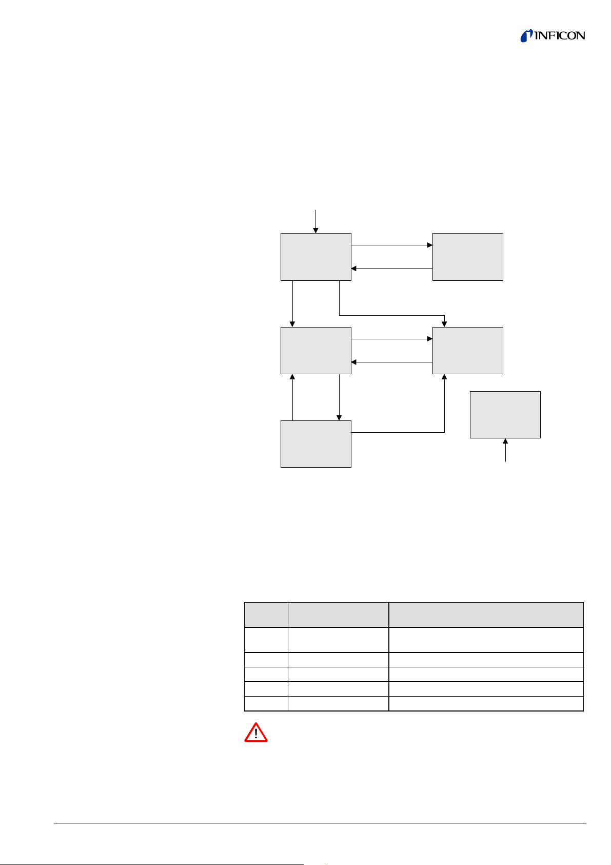
2.3.3 S-Device Supervisor
Object States
Power Applied, or
Reset Request from any state except CRITICAL FAULT, or
Perform Diagnostics Request from any state except CRITICAL FAULT or ABORT
Self-Test Failed
SELF-TEST
EXCEPTION
ABORT
CRITICAL FAULT
Critical Fault
from any state
Self-Test
Passed
Stop
Request
SELF-TESTING
IDLE
EXECUTING
Recover Request or
Exception Condition
Cleared
Abort Request
Abort Request
Recover Request
Start
Request
Abort Request
2.3.4 S-Device Supervisor
Common Services
Abort - Used to transition the device application objects to the aborted state. This
service request may be (and generally will) originated internally, from application
objects.
Recover - Used to transition the device application objects, out of the abort state,
to the idle state. This service request may be originated internally, from application
objects.
Perform_Diagnostics - Used to instruct the DS object to perform a diagnostic test.
Service
Service Name Description of Service
Code
0E
Get_Attributes_Single Returns the contents of the specified
h
attribute.
10
05
06
07
Set_Attributes_Single Modifies an attribute value.
h
Reset
h
Start Starts the device execution.
h
Stop
h
Resets the device to the Self-Testing state.
Moves the device to the Idle state.
The device transitions from the IDLE state to the EXECUTING state by a
START Request (Service Code 06
) or by the receipt of the first valid I/O
h
data.
You will not get any valid measurement values from the device until this ser-
vice has been requested or the I/O-poll message has been received.
tira40e1 (2005-04) BCG450SDv1.cp 15
Page 16

2.3.5 S-Device Supervisor
Object Specific Services
Service
Service Name Description of Service
Code
4B
4ChRecover
Abort
h
Moves the device to the Abort state
Moves the device out of the Abort state
4DhPerform_Diagnostics Causes the device to perform a set of
diagnostic routines
Explanation to
Service code 4D
h
• DS Object Service Parameter dictionary
Parameter Form Description
TestID USINT Type and possibly detail of diagnostic test to be
performed
• TestID parameter
The following values are defined for the TestID parameter for the
Perform_Diagnostics Service Request:
Attribute Value State
0 Standard
Type "Standard" is specified if there is only one type of diagnostic defined or if
there are more than one including a type standard.
2.4 S-Analog Sensor Object
Class Code 31
= 49
h
d
2.4.1 Class Attributes
Attribute ID Access
Rule
1 Get Revision UINT Revision of this object Note: All class definitions are
2 Get Max
1)
32
Get Class
94 Get Active
95 Get Active
96 Get Number of
99 Get Subclass UINT Identifies a subset of additional class attributes,
Name DeviceNet
Data Type
UINT Maximum instance number of an object currently
Instance
USINT Indicates whether the complete gauge (including
Level
Status
Extension
Specified
Value
by Data
Type
UINT Identifies the object instance that is providing the
Instance
Number
USINT Identifies the number of gauge instances present in
Gauges
Description of Attribute Semantics of Values
required to include this class attribute.
created in this class level of the device.
instances Capacitance Diaphragm Gauge, Pirani
and Hot Ion) measures above or below its maximum or minimum measurement range.
Is used by assemblies to produce this class-level
attribute, instead of the Value (Attribute ID 6) of the
S-Analog Sensor Instances.
Value which is copied into the Active Value for all
input Assemblies and the Alarm/Warning Exception
Details for the S-Device Supervisor object.
→ Behavior section.
the device.
services and behaviors.
The current value
assigned to this attribute is one (01).
The largest Instance
number of a created
object at this class
hierarchy level.
Bit 0: Reading Invalid
Bit 1: Overrange
Exceeded
Bit 2: Underrange
Exceeded
Default = 1
3
1 Instance Selector
1)
This attribute is not part of the actual S-Analog Sensor Specification, bit is at
this time in preparation to be implemented as shown. Changes may be possible
until the new specificationis published.
16 tira40e1 (2005-04) BCG450SDv1.cp
Page 17
Active Value
Assemblies or connections may produce this class-level attribute, instead of the
Value (Attribute ID 6) of the active S-Analog Sensor instance. The S-Analog Sensor class-level attribute Active Instance Number identifies the object instance that is
currently active and providing the Value to the Active Value class-level attribute
which is, in turn, produced by the input assemblies that have Active Value as a
member.
Active Instance Number
Number of Gauges
Class Level Status
Extension
The device internally modifies this attribute, as required, to identify the S-Analog
Sensor object instance providing the Value member which is copied into the Active
Value for all Input Assemblies and the Alarm/Warning Exception Details for the
S-Device Supervisor object.
The Active Instance Number will be modified based upon the Active Value in order
that the best gauge, corresponding to a given S-Analog Sensor instance, will be
active for the given measurement range.
This attribute is used to determine the size of all Input Assemblies within a node.
Because the gauge has three different measurement principles (Pirani, capacitance
diaphragm gauge, hot ionization gauge) this attribute is supported to give you the
information whether the gauge is outside the specified measurement range.
Gauge exposed to
Class Level Status Extension
pressure range
5×10
-10
… 1500 mbar
all bits set to "0"
>1500 mbar bits "Reading Invalid" and "Overrange Exceeded" set
<5×10
-10
mbar
bits "Reading Invalid" and "Underrange Exceeded" set
The Class Level Status Extension attribute is mapped to the Device Exception
Detail Warning Byte 0 of the Device Supervisor Object.
2.4.2 Instance Attributes
Three S-Analog Sensor Instances (Instance 1, Instance 2, Instance 21 and Instance 22) are available. Instance 1 represents the physical sensor reading of the
heat transfer vacuum gauge (pressure), Instance 2 represents the physical sensor
reading of the hot cathode ion gauge (pressure).
Instance 21 and Instance 22 represent the value of the Setpoint A and Setpoint B.
2.4.2.1 Instance Attributes of
Instance 1 /
Pirani Instance
AttributeIDAccess Rule NV/VName DeviceNet Data
3 Set /Cond.
→ below
NV Data Type USINT Determines the
Following is the Instance 1 with the subclass extension of the heat transfer vac-
uum gauge (pirani gauge) part of the BCG450-SD. This instance is used to provide control and status information for the Pirani gauge part of the BCG450-SD.
Description of
Type
Attribute
Data Type of Value
and all related
attributes as specified in this table.
4 Set
→ below
NV Data Units UINT Determines the
Units context of
Value and all related attributes.
5 Get V Reading Valid BOOL Indicates that the
Value attribute
contains a valid
value.
6 Get V Value INT or specified
Analog input value The corrected, converted, cali-
by Data Type
Semantics of Values
→ "Semantics" section below.
Int C3
float CA
[default]
h
h
Supported Values:
Counts 1001
mbar 1308
Torr 1301
Pascal 1309
[default]
h
h
h
h
0 = invalid
1 = valid
(invalid: e.g., not warmed up
yet)
brated final value of the sensor.
→ "Semantics" section below.
tira40e1 (2005-04) BCG450SDv1.cp 17
Page 18

AttributeIDAccess Rule NV/VName DeviceNet Data
Type
7 Get V Status BYTE Alarm and Warning
10 Get NV Full Scale INT or specified
by Data Type
25 Set NV Safe State USINT Specifies the be-
26 Set NV Safe Value INT or specified
by Data Type
32 Get NV Overrange INT or specified
by Data Type
33 Get NV Underrange INT or specified
by Data Type
94 Get V Sensor Warning Struct of Byte Bit definitions of
95 Get V Sensor Alarm Struct of Byte Bit definitions of
96 Get V Status Extension BYTE Bit-mapped byte
99 Get NV Subclass UINT Defines a subset of
Description of
Attribute
State of this object
instance
The Value of Full
Scale for the sensor.
havior for the Value
for states other
than Execute
The Value to be
used for Safe State
= Safe Value
Specifies the highest valid Value
Specifies the
lowest valid Value
Sensor Warnings
Sensor Alarms
providing additional
status bits
additional attributes, services and
behaviors.
Semantics of Values
Always zero, because Alarm
and Warning Trip Points are not
implemented
The value of attribute Value
corresponding to the Full Scale
calibrated measurement of the
sensor.
[default] = maximum allowable
value for the Data Type
→ "Semantics" section below.
[default] = 0
→ "Semantics" section below.
[default] = 0
The value above which attribute
Reading Valid is set to invalid.
[default] = maximum allowable
value for the Data Type
The value below which attribute
Reading Valid is set to invalid.
[default] = minimum allowable
value for the Data Type
0 = [default]
→ "Semantics" section
0 = [default]
→ "Semantics" section
Bit description:
0 Reading Invalid
(Logical Inversion of
Reading Valid)
1 Overrange Exceeded
2 Underrange Exceeded
02 = Heat Transfer Vacuum
Gauge
2.4.2.2 Semantics of S-Analog
Sensor Instance 1
Data Type
Data Unit
18 tira40e1 (2005-04) BCG450SDv1.cp
All Data Type attributes use the enumerated values integer or float
(→ Appendix A).
The Data Type value will be set automatically based upon the first valid I/O connection established by the device.
If no established I/O connections exist, which include an attribute from this object,
then the Data Type attribute is settable provided that the object is in the Idle State.
Note: Using data type integer in combination with a pressure unit (mbar, Torr or Pa)
will obviously not produce reasonable values below 1.
The Data Unit is only settable in the IDLE state.
Page 19

Value
An S-Analog Sensor object instance derives a reading from a physical analog sensor. The reading is converted to the data type and units specified for the Value
attribute.
Using Counts and INT the following conversion has to be used:
Safe State
Safe Value
Counts = [ log
where: k
k
k
mbar
Torr
Pa
(pressure) + k ] × 2000
10
= 12.5
= 12.624903
= 10.5
This attribute specifies what value will be held in Value for states other than Exe-
cuting. The purpose of this mechanism is to allow other devices, who may be using
this Value to transition to (or remain in) a safe state in the event of this device
transitioning to a FAULT, IDLE, or ABORT state. The following values are defined:
Attribute Value State
0 Zero
1 Full Scale
2 Hold Last Value
3 Use Safe Value
For Safe State set to Use Safe Value, this attribute holds the value to which the
Value attribute will be set for object instance states other than Executing.
Sensor Alarm
16 Bits are used as Sensor faults. Sensor Alarm Byte 1 is mapped to the Device
Exception Detail Alarm 3, Sensor Alarm Byte 0 is mapped to the Device Exception
Detail Alarm 2.
Data Component Bit 7 Bit 6 Bit 5 Bit 4 Bit 3 Bit 2 Bit 1 Bit 0
Sensor Alarm Byte 0
Sensor Alarm Byte 1
Sensor Warning
00000000
000000
Electronics
Failure
0
16 Bits are used as Sensor Warnings. Sensor Warning Byte 0 is mapped to the
Device Exception Detail Warning 3, Sensor Warning Byte 0 is mapped to the
Device Exception Detail Warning 4.
Data Component Bit 7 Bit 6 Bit 5 Bit 4 Bit 3 Bit 2 Bit 1 Bit 0
Sensor Warning Byte 0
Sensor Warning Byte 1
Status Extension
00000000
000000
Electronics
Warning
0
8 Bits providing the current sensor alarm state of the instance
Data Component Bit 7 Bit 6 Bit 5 Bit 4 Bit 3 Bit 2 Bit 1 Bit 0
Sensor Alarm Byte 0
00000Underrange
Exceeded
Overrange
Exceeded
Reading
Invalid
tira40e1 (2005-04) BCG450SDv1.cp 19
Page 20

2.4.2.3 Instance Attributes of
Instance 2 / Hot Cathode
Ion Gauge
Following is the Instance 2 with the subclass extension of the hot cathode ion
gauge part of the BCG450-SD. This instance is used to provide control and status
information for the hot cathode ion gauge part of the BCG450-SD.
AttributeIDAccess
Rule
3 Set/Cond.
→ below
4
5 Get V Reading
6 Get V Value INT or speci-
7 Get V Status BYTE Alarm and Warning State
10 Get NV Full Scale INT or speci-
25 Set NV Safe State USINT Specifies the behavior for
26 Set NV Safe
32 Get NV Overrange INT or speci-
33 Get NV Under-
88 Get V Degas
91 Get V Emission
93 Get V Emission
94 Get V Sensor
95 Get V Sensor
→
"Semantics"
NV/V Name DeviceNet
Data Type
NV Data Type USINT Determines the Data Type
NV Data Units ENGUNITS Determines the Units con-
BOOL Indicates that the Value
Valid
fied by Data
Type if supported
fied by Data
Type if supported
INT or speci-
Value
range
Status
Current
Status
Warning
Alarm
fied by Data
Type if supported
fied by Data
Type if supported
INT or specified by Data
Type if supported
BOOL Indicates current degas
REAL Indicates setting level of
BOOL Indicates whether the
Structure of
Byte
Structure of
Byte
Description of Attribute Semantics of Values
of Value and all related
attributes as specified in
this table.
text of Value and all related
attributes.
attribute contains a valid
value.
Analog input value The corrected, converted, calibrated
of this object instance
The Value of Full Scale for
the sensor.
the Value for states other
than Execute
The Value to be used for
Safe State = Safe Value
Specifies the highest valid
Value
Specifies the lowest valid
Value
state
emission current in amps
emission is turned ON or
OFF
→ "Semantics" section
[default] = INT
→ "Semantics" section
[default] = Counts
0 = invalid
1 = valid
(invalid: e.g., not warmed up yet)
final value of the sensor.
→ "Semantics" section
→ "Semantics" section
The value of attribute Value corresponding to the Full Scale calibrated
measurement of the sensor.
[default] = maximum allowable value
for the Data Type
→ "Semantics" section
[default] = 0
→ "Semantics" section
[default] = 0
The value above which attribute
Reading Valid is set to invalid.
[default] = maximum allowable value
for the Data Type
The value below which attribute
Reading Valid is set to invalid.
[default] = minimum allowable value
for the Data Type
0 OFF
1 ON
0, 25 µA, 5 mA, 20 mA
0 OFF
1 ON
default 0 → "Semantics"
default 0 → "Semantics"
20 tira40e1 (2005-04) BCG450SDv1.cp
Page 21

AttributeIDAccess
Rule
96 Get V Status
NV/V Name DeviceNet
Data Type
BYTE Bit mapped byte providing
Extension
Description of Attribute Semantics of Values
additional status bits
99 Get NV Subclass UINT Identifies the subset of
additional attributes, services and behaviors for hot
cathode ion gauges
100 Get NV State
Emission
Control
USINT Represents the state ac-
cording the service Set
Control Mode
Mode
2.4.2.4 Semantics of S-Analog
Sensor Instance 2
Bit description:
0 Reading Invalid
(Logical Inversion of
Reading Valid)
1 Overrange Exceeded
2 Underrange Exceeded
5 Hot Cathode Ion Gauge
0 = Auto
1 = Manual
Data Type
Value
→ Instance 1
An S-Analog Sensor object instance derives a reading from a physical analog sen-
sor. The reading is converted to the data type and units specified for the Value
attribute.
Using Counts and INT the following conversion has to be used:
Safe State
Safe Value
Sensor Alarm
Counts = [ log
where: k
k
k
mbar
Torr
Pa
→ Instance 1
→ Instance 1
16 Bits are used as sensor faults . Sensor Alarm Byte 0 is mapped to the Exception
(pressure) + k ] × 2000
10
= 12.5
= 12.624903
= 10.5
Detail Alarm 4, Sensor Alarm Byte 1 ismapped to the Exception Detail Alarm 5.
Data Component Bit 7 Bit 6 Bit 5 Bit 4 Bit 3 Bit 2 Bit 1 Bit 0
Sensor Alarm Byte 0
Sensor Alarm Byte 1
00000000
000000
Electronics
Failure
0
Sensor Warning
16 Bits are used as sensor warnings. Sensor warning Byte 0 is mapped to the
Exception Detail Warning 5, Sensor warning Byte 0 is mapped to the Exception
Detail Warning 6.
Data Component Bit 7 Bit 6 Bit 5 Bit 4 Bit 3 Bit 2 Bit 1 Bit 0
Sensor Warning Byte 0
Sensor Warning Byte 1
tira40e1 (2005-04) BCG450SDv1.cp 21
00000000
mbar.
Pressure
too high for
degas
000
0000
The bit "Pressure too high for degas" will be set if the pressure is above
-6
7.2×10
pressure is below 7.2×10
mbar when a degas service is requested. The bit will be reset when the
-6
Page 22

Status Extension
8 Bits providing the current sensor alarm state of the instance
Data Component Bit 7 Bit 6 Bit 5 Bit 4 Bit 3 Bit 2 Bit 1 Bit 0
Sensor Alarm Byte 0
00000Underrange
Exceeded
Overrange
Exceeded
Reading
Invalid
22 tira40e1 (2005-04) BCG450SDv1.cp
Page 23

2.4.2.5 Instance Attributes of
Instance 3 / Capacitance
Diaphragm Gauge
Following is the Instance 3 with the subclass extension of the capacitance
diaphragm gauge part of the BCG450-SD. This instance is used to provide control
and status information for the capacitance diaphragm gauge part of the
BCG450-SD.
AttributeIDAccess
Rule
3 Set/Cond.
→ below
NV/V Name DeviceNet
Description of Attribute Semantics of Values
Data Type
NV Data Type USINT Determines the Data Type
of Value and all related
attributes as specified in
this table.
4
→
"Semantics"
NV Data Units ENGUNITS Determines the Units con-
text of Value and all related
attributes.
5 Get V Reading
Valid
BOOL Indicates that the Value
attribute contains a valid
value.
6 Get V Value INT or speci-
Analog input value The corrected, converted, calibrated
fied by Data
Type if supported
7 Get V Status BYTE Alarm and Warning State
of this object instance
10 Get NV Full Scale INT or speci-
fied by Data
The Value of Full Scale for
the sensor.
Type if supported
25 Set NV Safe State USINT Specifies the behavior for
the Value for states other
than Execute
26 Set NV Safe
Value
INT or specified by Data
The Value to be used for
Safe State = Safe Value
Type if supported
32 Get NV Overrange INT or speci-
fied by Data
Specifies the highest valid
Value
Type if sup-
ported
33 Get NV Under-
range
INT or specified by Data
Specifies the lowest valid
Value
Type if sup-
ported
94 Get V Sensor
Warning
95 Get V Sensor
Alarm
96 Get V Status
Extension
Structure of
Byte
Structure of
Byte
BYTE Bit mapped byte providing
additional status bits
99 Get NV Subclass UINT Identifies the subset of
additional attributes, serv-
ices and behaviors for hot
cathode ion gauges
→ "Semantics" section
[default] = INT
→ "Semantics" section
[default] = Counts
0 = invalid
1 = valid
(invalid: e.g., not warmed up yet)
final value of the sensor.
→ "Semantics" section
→ "Semantics" section
The value of attribute Value corresponding to the Full Scale calibrated
measurement of the sensor.
[default] = maximum allowable value
for the Data Type
→ "Semantics" section
[default] = 0
→ "Semantics" section
[default] = 0
The value above which attribute
Reading Valid is set to invalid.
[default] = maximum allowable value
for the Data Type
The value below which attribute
Reading Valid is set to invalid.
[default] = minimum allowable value
for the Data Type
default 0 → "Semantics"
default 0 → "Semantics"
Bit description:
0 Reading Invalid
(Logical Inversion of
Reading Valid)
1 Overrange Exceeded
2 Underrange Exceeded
5 Capacitance Diaphragm Gauge
tira40e1 (2005-04) BCG450SDv1.cp 23
Page 24

2.4.2.6 Semantics of S-Analog
Sensor Instance 3
Data Type
Value
→ Instance 1
An S-Analog Sensor object instance derives a reading from a physical analog sensor. The reading is converted to the data type and units specified for the Value
attribute.
Using Counts and INT the following conversion has to be used:
(pressure) + k ] × 2000
10
= 12.5
= 12.624903
= 10.5
Safe State
Safe Value
Sensor Alarm
Counts = [ log
where: k
k
k
mbar
Torr
Pa
→ Instance 1
→ Instance 1
16 Bits are used as sensor faults. Sensor Alarm Byte 0 is mapped to the Exception
Detail Alarm 0, Sensor Alarm Byte 1 is mapped to the Exception Detail Alarm 1.
Data Component Bit 7 Bit 6 Bit 5 Bit 4 Bit 3 Bit 2 Bit 1 Bit 0
Sensor Alarm Byte 0
Sensor Alarm Byte 1
0000000Diaphragm
000000
Electronics
Failure
Failure
0
Sensor Warning
16 Bits are used as sensor warnings. Sensor Warning Byte 0 is mapped to the
Exception Detail Warning 1, Sensor Warning Byte 1 is mapped to the Exception
Detail Warning 2.
Data Component Bit 7 Bit 6 Bit 5 Bit 4 Bit 3 Bit 2 Bit 1 Bit 0
Sensor Warning Byte 0
Sensor Warning Byte 1
Status Extension
00000000
000000Electronics
Warning
0
8 Bits providing the current sensor alarm state of the instance
Data Component Bit 7 Bit 6 Bit 5 Bit 4 Bit 3 Bit 2 Bit 1 Bit 0
Sensor Alarm Byte 0
00000Underrange
Exceeded
Overrange
Exceeded
Reading
Invalid
24 tira40e1 (2005-04) BCG450SDv1.cp
Page 25

2.4.2.7 Object-Specific Services
on Instance 3 / Capacitance
Diaphragm Gauge
USER ATM Adjust
Service
Code
32
User ATM Adjust Service Data Field Parameters:
Parameter Datatype
User ATM Adjust BOOL 0 = Unlock user ATM Adjust
There are no state transitions associated with the invocation of this service. It is
therefore, incumbent upon the user to establish the device into the desired configuration prior to, and during the execution of this service. This will generally involve exposing the sensor to a known environment and treating the values read
during execution of the services accordingly.
A success service response indicates that the service was accepted and the application process started.
To perform the User Atmosphere Adjust Request proceed as follows:
Service Name Description of Service
User Atmosphere
h
Adjust
Performs an Atmosphere Adjust Piezo to
Capacitance Diaphragm Gauge
1 = executes an User ATM Adjust and lock
n Vent the gauge to atmosphere
o Unlock the user ATM Adjust wit a target value of "0"
p Execute the User Atmosphere Adjust Service with a target value of "1".
The pressure value of the amtmosphere pressure sensor is then tracked to the
value of the Capacitance Diaphragm Gauge.
tira40e1 (2005-04) BCG450SDv1.cp 25
Page 26
2.4.2.8 Instance Attributes of
Instance 21 / Setpoint A
(Instance 22 / Setpoint B)
AttributeIDAccess
Rule
3 Set / Con-
ditional:
→
Instance 1
NV/V Name DeviceNet
Description of Attribute Semantics of Values
Data Type
NV Data Type USINT Determines the Data Type
of Value and all related
attributes as specified in
this table.
4 Get NV Data Units UINT Determines the Units
context of Value and all
related attributes.
5 Get V Reading
Valid
BOOL Indicates that the Value
attribute contains a valid
value.
6 Get V Value INT or
specified by
Data Type
The value of the
Setpoint A (Setpoint B)
relay.
7 Get V Status BYTE Alarm and Warning State
of this object instance
100 NV Set Setpoint
Function
USINT Defines whether the relay
is controlled by the according potentiometer or by
the atmosphere pressure
sensor combined with the
Capacitance Diaphragm
Gauge pressure value.
101 NV Set Percentage
of
Atmosphere
1)
USINT If the pressure value
(active value) is within a
"window" specified by this
attribute from the
atmosphere pressure sensor value, the relay will be
activated. For further
details → below.
→ "Semantics" section below.
int C3
float CA
[default]
h
h
Supported Values:
Counts 1001
mbar 1308
Torr 1301
Pascal 1309
[default]
h
h
h
h
0 = invalid
1 = valid
→ "Semantics" section below.
Behavior as Trip Point LOW
0 = Setpoint (default)
1 = Atmosphere Control
0 … 140
Example:
1 1%
50 50%
default value = 5%
102 V Get Atmosphere
reached
USINT If the pressure of the
gauge is within a percentage of the atmosphere
pressure this byte has the
value 1. If the pressure is
below this window, the
value is 0.
1)
Atmospheric pressure threshold (→ 28).
The upper pressure limit of the
gauge is 1500 mbar. At an
atmosphere pressure above
1000 mbar and a percentage
of atmosphere of 150% the
relay will never be activated.
If the device is in Safe State the value
of this attribute is "0".
26 tira40e1 (2005-04) BCG450SDv1.cp
Page 27
Status
A bit mapped byte which indicates the Alarm and Warning Exception status of the
object instance. The following definition applies:
Bit Definition
0 High Alarm Exception: 0 = cleared 1 = set
1 Low Alarm Exception: 0 = cleared 1 = set
2 High Warning Exception: 0 = cleared 1 = set
3 Low Warning Exception: 0 = cleared 1 = set
4 Reserved
5 Reserved
6 Reserved
7 Reserved
Setpoints
If the pressure (attribute 6, instance 1 and 2) decreases below the Setpoint value
(attribute 6, instance 21 and 22) an alarm or warning exception condition will be
generated. The hysteresis is set to 10%.
For example: A Set Point value of 100 will result in an exception condition being set
when the Value is below 100 and cleared when the Value increases above 110.
The setpoints can only be read by DeviceNet. It is not possible to set the
values or to influence the state of the relays by DeviceNet. Even if the device is not allocated, the relay status is set corresponding to the voltage adjusted by the two setpoint potentiometers.
Only in case of a microcontroller RESET (for example reset on Identity Object), the relays will be reset too.
The setpoint is available in the actual pressure unit and data type. If the pressure
unit "Counts" is set, use the following formula for the conversion from Counts to
pressure:
p
mbar
where: k
=10
mbar
k
Torr
k
Pa
Counts / 2000 - k
= 12.5
= 12.624903
= 10.5
The relation between setpoint and voltage is:
p
mbar
where: c
=10
mbar
c
Torr
c
Pa
(U - 7.75) / 0.75 + c
=0
= -0.125
=2
The setpoints are only activated, if the pressure is below 100 mbar, therefore a
setpoint above 100 mbar can not be realised.
tira40e1 (2005-04) BCG450SDv1.cp 27
Page 28

Setpoint function
"
Atmosphere Control"
The setpoint function "Atmosphere Control" is used to decide whether the measured pressure is within a specified percentage of the atmospheric pressure
(→ diagram below).
Attribute 101 "Percentage of Atmosphere" is used to define the percentage of atmospheric pressure. If the measured pressure is within this window, the corresponding relay will be activated (→ [4]).
A fixed hysteresis of 2% of the atmospheric pressure threshold is programmed.
The following rule applies:
Atmospheric pressure × N
Atmospheric pressure threshold =
—————————————
100
Where:
Atmospheric pres-
sure threshold
[mbar] : If the pressure inside the vacuum chamber rises
above this threshold, the relay "Atmosheric pressure reached" is energized.
Atmospheric
[mbar] : Atmospheric pressure (100%, ambient)
pressure
N [%] : "Percentage of Atmosphere"
(1 … 140%, default value = 5%)
(Example values in the diagram below are printed in italic)
Measuring signal
(Pressure p)
1500 mbar
980 mbar
833 mbar
Upper limit of measuring range of gauge
Atmospheric pressure (100%, am bient)
e
u
"Percentage of Atmosphere"
(85%)
(Atmospheric pressure
threshold)
M
e
l
a
v
d
e
r
u
s
a
816 mbar
Hysteresis
(2% of atmospheric
pressure threshold)
1)
1)
Relay status "Atmospheric pressure rea c hed"
1)
The (piezo) sensor measuring atmospheric pressure can be
calibrated to the value of the Capacitance Diaphragm Gauge pressure
(
→ 25).
28 tira40e1 (2005-04) BCG450SDv1.cp
Page 29

2.4.3 Common Services
The S-Analog Sensor Object provides the following Common Services:
2.4.4 Object-Specific Services
on Instance 2 / Hot
Cathode Ion Gauge
2.4.4.1 SET DEGAS STATE
Set Degas State Request
Service Data Field
parameters
Service
Service Name Description of Service
Code
0EhGet_Attribute_Single Returns the contents of the specified attribute.
10
Service
Set_Attribute_Single Modifies an attribute value.
h
Service Name Description of Service
Code
61
Set Degas State Activates/deactivates degas mode according to
h
the parameter Degas State. Degas mode may
be terminated either automatically by device
timeout (3 min) or remotely by this service.
Parameter Data Type Description Semantics of Values
Degas
State
BOOL
switches Degas OFF
0
1
switches Degas ON
The pressure has to be below 7.2×10⁻⁶ mbar before degas can be switched on.
2.4.4.2 SET EMISSION STATE
Set Emission State Request
Service Data Field
parameters
Service
Service Name Description of Service
Code
62
h
Set Emission
State
Turns the filament on and off according to the
parameter Emission State
Parameter Data Type Description Semantics of Values
Emission
State
BOOL
→ below
emission OFF
0
1
emission ON
If the gauge is in the Emission User Mode "Manual", please note:
• The service SET EMISSION STATE ⇒ ON may be executed only, if
the pressure is below 2.4
-2
×10
mbar. If the pressure is higher, an
Object State Conflict error message will be returned.
• If the pressure rises above 3.2×10
-2
mbar, the gauge will switch off
the emission automatically. The gauge will then show the Pirani
value.
• If the gauge is measuring in the ion gauge measuring range and the
service Set Emission State
switched off and the minimum Pirani value 1
⇒ OFF ist executed, the emission will be
-3
×10
mbar will be dis-
played.
tira40e1 (2005-04) BCG450SDv1.cp 29
Page 30

2.4.4.3 Emission Control Mode
Service
Code
32
h
Service Name Description of Service
Set Emission
Control Mode
• Automatic
The Emission is switched on and off by the
Pirani automatically.
• Manual
The emission has to be switched on and off
by the user
Set Emission Control Mode
Data Field
Emission User Modes
2.4.5 Behavior
Parameter Data Type Description Semantics of Values
Emission
User Mode
BOOL
→ below
Automatic Mode (default)
0
1
Manual Mode
State
Automatic: The emission is automatically switched ON and OFF.
The user can switch the emission OFF by using the Set Emission
State service.
If the emission is switched off manually, the emission will be automatically switched on again, after the pressure rose above 3.2
and falls below 2.4
-2
×10
mbar again.
×10
-2
mbar
Manual: The emission has to be switched on and off by the user, using the Set
Emission State service. The Set Emission State service may be
executed only, if the pressure is below 2.4
-2
×10
mbar. If the pressure
is higher, an Object State Conflict error will be returned.
If the emission is switched on and the pressure rises above 3.2
×10
-2
mbar, the
gauge will switch off the emission automatically.
Data Type
The following behavior with respect to Data Type applies:
The Data Type value will be set automatically based upon the first valid I/O con-
nection established by the device.
If no established I/O connections exist, which include an attribute from this object,
then the Data Type attribute is settable provided that the object is in the Idle State.
The following example demonstrates this behavior:
A device specifies an instance of the S-Analog Sensor object as well as two static
Assembly object instances, both with data attribute components mapped to this
object instance. Assembly object instance ID 1 specifies INT data types and Assembly object instance ID 2 specifies REAL data types.
After the device is online, it is configured with an I/O connection to Assembly instance ID 2. When the connection transitions to the Established State, this object
instance attribute Data Type is automatically set with the value for REAL before
any data is communicated to, or from the object instance. Any subsequent attempt
to connect to Assembly instance ID 1 would then be rejected and result in an
INVALID ATTRIBUTE VALUE error with the additional error code indicating the ID
of the offending attribute, which in this case would be the connection path.
30 tira40e1 (2005-04) BCG450SDv1.cp
Page 31

3 I/O Assembly Object
3.1 I/O Assembly Instances
Class Code 04
h
A collection of assembly objects allows the sending of attributes from different
application objects in one message (i.e. Polling I/O).
The following table identifies the I/O assembly instances supported by the gauge
device.
Number Type Name
1 Input Pressure Value (Active Instance)
2 Input Exception Status and INT Pressure Value
(Active Instance)
4 Input REAL Pressure Value (Active Instance)
5 Input Exception Status and REAL Pressure Value
(Active Instance)
8 Input Exception Status
9 Input Active Instance, Active Pressure Value
10 Input Exception Status and Active Instance and INT Active
Pressure Value
12 Input Active Instance
REAL Active Pressure Value
13 Input Exception Status
Active Instance
REAL Active Pressure Value
tira40e1 (2005-04) BCG450SDv1.cp 31
Page 32

3.2 I/O Assembly Object
Instance Data Attribute
Format
In order to maintain consistency, this device type will only allow connections to
either INT or REAL based Assembly instances (
Once a valid connection is established, attempts to configure connections to a
different type of Assembly instance will return an error.
The I/O Assembly DATA attribute has the format shown below:
Instance Type Byte Bit 0 … 7
1 Input 0 INT Pressure Value (low byte)
1
2 Input 0 Exception Status; Class 48, Instance 1,
Attribute 12
1 INT Pressure Value (low byte)
2 Class 49, Active Value
4 Input 0 REAL Pressure Value (low byte)
1
2 Class 49, Active Instance Value
3
5 Input 0 Exception Status Class 48, Instance 1,
Attribute 12
1 REAL Pressure Value (low byte)
2 Class 49, Active Instance Value
3
4
8 Input 0 Exception Status ; Class 48, Instance 1,
Attribute 12
9 0 Active Instance
1
2 INT Active Pressure Value
3
10 Input 0 Exception Status
1 Active Instance
2
3 INT Active Pressure Value
4
12 Input 0 Active Instance
1
2 REAL Pressure Value
3
4
5
13 Input 0 Exception Status
1 Active Instance
2
3 REAL Pressure Value
4
5
6
→ Data Type definition 18).
32 tira40e1 (2005-04) BCG450SDv1.cp
Page 33

Appendix
A: Range of Values
B: Specific Codes
C: Conversion of a Floating
Number According to
IEEE 754
General
Number received
1. Reverse the sequence of
the HEX words
Integer int
Unsigned integer uint
–32767
0
… 65535
… 32768
Float float according IEEE 754
Manufacturer product code 13 = BCG450-SD
AA BB CC DD
DD
(4-Byte, floating format)
h
h
CC
Legend: XX
h
Hexadecimal number
h
(Radix = 16)
Decimal number (Radix = 10)
XX
d
Binary number (Radix = 2)
XX
b
BB
h
AA
h
2. Separate into bytes
3. Calculate
Converted number
SEEE EEEEbEMMM MMMMbMMMM MMMMbMMMM MMMM
Sign 8-Bit exponent 23-Bit mantissa
S EEEE EEEEbMMM MMMM MMMM MMMM MMMM MMMM
ØØ Ø
⎛
MMMMMMMMMMMMMMM MMMMMMMM
1+
⎜
⎜
⎝
= 1+
23
2
⎛
NNNNN
⎜
8388608
⎝
⎞
d
⎟
⎠
d
b
Ø
Sign = Exponent = Mantissa =
S
-1
XYZ
d
Sign × 2
(Exponent-127)
RSTUV
× Mantissa
d
b
b
⎞
⎟
⎟
⎠
tira40e1 (2005-04) BCG450SDv1.cp 33
Page 34

Example
Number received
1. Convert sequence of the
HEX words
2. Separate into bytes
3. Calculate
00 00 CA 42h (4-Byte, floating format)
42
h
0100 0010
Sign 8-Bit exponent 23-Bit mantissa
b
0 1000 0101
CA
h
1100 1010
b
00
h
0000 0000
b
b
100 1010 0000 0000 0000 0000
ØØ Ø
0
-1
1+
⎛
⎜
⎜
⎜
⎝
= 1+
23
2
⎛
4849664
⎜
8388608
⎝
00
h
0000 0000
⎞
0000 0000 0000 0000 1010 100
⎟
b
⎟
⎟
⎠
⎞
d
⎟
⎠
d
b
b
Converted number
D: Typical Start-Up
Procedure
Allocation process
ØØ
Sign = Exponent = Mantissa =
1 133 1.578125
(133-127)
1 × 2
The start up of a device is divided into the steps:
• Allocation process
• Setting of the EPR attribute
• Choice of the input and output assemblies
Send an allocation string as defined in the DeviceNet specification to the device
you want to allocate.
Set the bits in the allocation choice byte to 1 for these connections you want to use.
× 1.578125 = 101
34 tira40e1 (2005-04) BCG450SDv1.cp
Page 35

Example of the principal
allocation process.
Master MAC ID....0
Allocation choice: Explicit, Poll, bit strobe, COS
Slave address: 2
Allocated instances may not be valid for the BCG450-SD
⇒ Allocation String: 416 00 4B 03 01 57 00
Slave’s explicit/unconnected response message: 413 00 CB 00
Within the first allocation message the explicit connection has to be
established.
The I/O connections bit strobe and COS/Cyclic are not supported by the
BCG450-SD. Appendix D describes only the general allocation procedure for all devices (group 2 slave only).
Setting of the EPR Attribute
(expected packet rate)
After the allocation, the device activates an INACTIVITY WATCHDOG TIMER.
This timer has to be set for every single connection (connection object, attribute 9)
which is allocated in the allocation choice byte. This attribute defaults to 2500
(2500 ms) within explicit messaging connections, and to zero within an I/O connection. If the INACTIVITY WATCHDOG TIMER expires, the established connection will be released. With every message the device receives, this timer is reloaded with the value specified in the according connection object, therefore it normally doesn't expire. The value zero deactivates the INACTIVITY WATCHDOG
TIMER.
In this step the INACTIVITY WATCHDOG TIMER has to be set. In testing mode
you could use the value 0 to deactivate the INACTIVITY WATCHDOG TIMER.
In the following you see the strings for setting the EPR attribute (addresses as
specified above):
ID Message Body
414 00 10 05 01 09 00 00 set EPR of the explicit connection to zero
414 00 10 05 02 09 00 00 set EPR of the poll connection to zero
414 00 10 05 03 09 00 00 set EPR of the bit strobe connection to zero
414 00 10 05 04 09 00 00 set EPR of the COS/Cyclic connection to zero
The responses of the slave are:
ID Message Body
413 00 90 00 00 set EPR of the explicit connection to zero
Choice of the input and output
assemblies
Reading the configured
assemblies
tira40e1 (2005-04) BCG450SDv1.cp 35
You can specify which of the several input/output assemblies predefined in a device should be used for
Reading or setting of the input/output assemblies is possible only if the
corresponding connection (polling, change of state, bit strobe) has been allocated in the Allocation Message.
If you want to read the number of the chosen assembly, you must read the attributes 14 and 16 in the corresponding Instance of the Connection Object (Object
ID 5).
For reading this value, the connection has to be established. The EPR attribute
may be set.
Instance 2: Polling
Instance 3: Bit Strobe
Instance 4: Change of State/Cyclic
every single connection.
Page 36

Setting of assemblies
If you want to set the number of the chosen assembly, you have to set the attributes 14 and 16 in the corresponding instance of the connection object.
To set this value, the connection has to be allocated, but the EPR attribute
has not to be set to any value.
Examples
• Read a configured assembly (addresses as specified above):
Get single request:
ID Message Body
414 00 0E 05 02 0E get produced connection path (Request
for input assembly by master).
Get single response:
ID Message Body
413 00 8E 20 04 24 05 30 03 response from slave
The addressing format of the attribute values differs from the normal mode. A
connection path attribute that specifies class 4, Instance 5, and attribute ID 3 is
illustrated below:
Class #4 Instance #5 Attribute #3
20 04 24 05 30 03
The instance defines the assembly you want to use. This format has to be used
by the master in the request and is used by the slave in the response.
• Set the input assembly 04 for a Poll Connection (addresses as specified
above):
Set single request:
ID Message Body
414 80 00 10 05 02 10 20 04 first fragment
414 80 81 24 04 30 03 second fragment
Because the message body is longer than 8 bytes, the fragmented protocol has
to be used.
Set single response:
ID Message Body
413 80 C0 00 response on first fragment
413 80 C1 00 response on second fragment
36 tira40e1 (2005-04) BCG450SDv1.cp
Page 37

E: Literature
[1] www.inficon.com
Product descriptions and downloads
INFICON AG, LI–9496 Balzers, Liechtenstein
[2] www.odva.org
Open DeviceNet Vendor Association, Inc.
DeviceNet™ Specifications
[3] European Standard for DeviceNet EN 50325
[4] www.inficon.com
Operating Instructions
BCG450, BCG450-SD, BCG450-SP
tina40d1 / tina40e1
INFICON AG, LI–9496 Balzers, Liechtenstein
[5] www.inficon.com
Instruction Sheet
BCG450, BCG450-SD, BCG450-SP
tima40d1 / tima40e1
INFICON AG, LI–9496 Balzers, Liechtenstein
[6] www.inficon.com
Instruction Sheet
BCG450-SD, BCG450-SP
tima41d1 / tima41e1
INFICON AG, LI–9496 Balzers, Liechtenstein
tira40e1 (2005-04) BCG450SDv1.cp 37
Page 38

Notes
38 tira40e1 (2005-04) BCG450SDv1.cp
Page 39

Notes
tira40e1 (2005-04) BCG450SDv1.cp 39
Page 40

LI–9496 Balzers
Liechtenstein
Tel +423 / 388 3111
Fax +423 / 388 3700
reachus@inficon.com
t i ra40 e1
www.inficon.com
 Loading...