

Page 1
Operating Manual
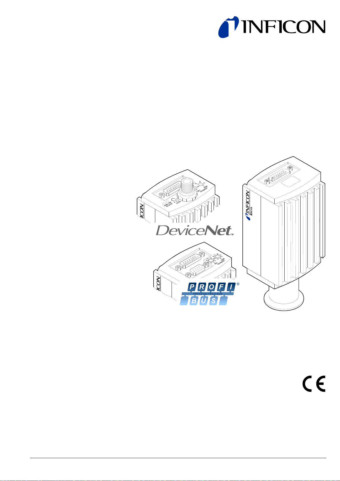
TripleGauge™
Bayard-Alpert Pirani Capacitance Diaphragm Gauge
BCG450
BCG450-SD
BCG450-SP
tina40e1-b (2011-04) 1
Page 2
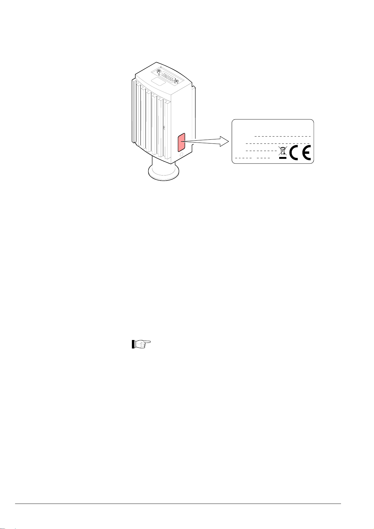
Product Identification
In all communications with INFICON, please specify the information on the product
nameplate. For convenient reference copy that information into the space provided
below.
INFICON AG, LI-9496 Balzers
Model:
PN:
SN:
V W
Validity
Intended Use
This document applies to products with the following part numbers:
BCG450 (without display)
353-550 (vacuum connection DN 25 ISO-KF)
353-551
(vacuum connection DN 40 CF-R)
353-561 (vacuum connection DN 25 ISO-KF, with baffle)
BCG450 (with display)
353-552 (vacuum connection DN 25 ISO-KF)
353-553
(vacuum connection DN 40 CF-R)
BCG450-SD (with DeviceNet interface and switching functions)
353-557 (vacuum connection DN 25 ISO-KF)
353-558
(vacuum connection DN 40 CF-R)
353-562 (vacuum connection DN 25 ISO-KF, with baffle)
BCG450-SP (with Profibus interface and switching functions)
353-554 (vacuum connection DN 25 ISO-KF)
353-556
(vacuum connection DN 40 CF-R)
The part number (PN) can be taken from the product nameplate.
If not indicated otherwise in the legends, the illustrations in this docu-
ment correspond to gauge with part number 353-552. They apply to the
other gauges by analogy.
All BCG450 versions are shipped with an instruction sheet (→ [8]). BCG450-SD
and BCG450-SP come with a supplementary instruction sheet describing the fieldbus interfaces and the switching functions (→ [9]).
We reserve the right to make technical changes without prior notice.
The BCG450, BCG450-SD and BCG450-SP gauges have been designed for
vacuum measurement of gases in the pressure range 5×10
-10
… 1500 mbar.
They must not be used for measuring flammable or combustible gases in mixtures
containing oxidants (e.g. atmospheric oxygen) within the explosion range.
The gauges can be operated in connection with the INFICON Vacuum Gauge
Controller VGC401, VGC402 or VGC403 or with other control devices.
2
tina40e1-b (2011-04)
Page 3

Functional Principle
Trademarks
Due to the combination of three sensor technologies incorporated in the gauge
(Capacitance diaphragm sensor, Pirani sensor and hot cathode ionisation sensor
(BA)), a minimized gas type dependence is achieved.
Between 10 mbar and atmospheric pressure, the capacitance diaphragm sensor
operates without any gas type dependence. Below 1 mbar, the Pirani sensor and
the hot cathode ionisation sensor take over with only a small gas type dependence.
-3
Between 1 … 10 mbar and 5×10
… 2×10⁻² mbar the gauges built in electronic
circuits take care of continuous and smooth crossovers between the ranges. Over
the whole measurement range, the measurement signal is output as a logarithm of
the pressure.
The hot cathode is switched on by the Pirani measurement system only below the
switching threshold of 2.4×10
off when the pressure exceeds 3.2×10
-2
mbar (to prevent filament burn-out). It is switched
-2
mbar.
Gauge adjustment is carried out automatically, no manual adjustment is required.
A user programmable atmospheric pressure switching function is incorporated.
DeviceNet™ Open DeviceNet Vendor Association, Inc.
TripleGauge™ INFICON AG, Balzers
tina40e1-b (2011-04) 3
Page 4

Contents
Product Identification 2
Validity 2
Intended Use 2
Functional Principle 3
Trademarks 3
1
Safety 6
1.1 Symbols Used 6
1.2 Personnel Qualifications 6
1.3 General Safety Instructions 7
1.4 Liability and Warranty 7
2 Technical Data 8
3 Installation 13
3.1 Vacuum Connection 13
3.1.1 Removing and Installing the Electronics Unit 15
3.1.2 Using the Optional Baffle 16
3.2 Power Connection 17
3.2.1 Use With INFICON VGC40x Vacuum Gauge Controller 17
3.2.2 Use With Other Controllers 18
3.2.2.1 Making an Individual Sensor Cable 18
3.2.2.2 Making a DeviceNet Interface Cable (BCG450-SD) 21
3.2.2.3 Making a Profibus Interface Cable (BCG450-SP) 22
3.2.3 Using the Optional Power Supply (With RS232C Line) 23
4 Operation 25
4.1 Measuring Principle, Measuring Behavior 25
4.2 Operational Principle of the Gauge 27
4.3 Putting the Gauge Into Operation 28
4.4 Degas 28
4.5 Emission Control Mode 29
4.6 Atmosphere Switching Function 30
4.6.1 Functional Principle 30
4.6.2 Programming the Atmospheric Pressure Threshold 31
4.6.3 Wiring the relay "Atmospheric Pressure Reached" (BCG450) 32
4.7 Display (BCG450) 32
4.8 RS232C Interface 33
4.8.1 Description of the Functions 34
4.8.1.1 Output String (Transmit) 34
4.8.1.2 Input String (Receive) 36
4.9 DeviceNet Interface (BCG450-SD) 38
4.9.1 Description of the Functions 38
4.9.2 Operating Parameters 38
4.9.2.1 Operating Software 38
4.9.2.2 Node Address Setting 38
4.9.2.3 Data Rate Setting 39
4.9.3 Status Lights 39
4.10 Profibus Interface (BCG450-SP) 40
4.10.1 Description of the Functions 40
4.10.2 Operating Parameters 40
4.10.2.1 Operating Software 40
4.10.2.2 Node Address Setting 40
4.11 Switching Functions (BCG450-SD, -SP) 41
4.11.1 Setting the Switching Functions 41
5 Deinstallation 43
4
tina40e1-b (2011-04)
Page 5

6 Maintenance, Repair 45
6.1 Maintenance 45
6.1.1 Cleaning the Gauge 45
6.2 Adjusting the Gauge 45
6.3 Adjusting the Atmosphere Sensor 45
6.4 What to Do in Case of Problems 47
6.5 Replacing the Sensor 49
7 Options 50
8 Spare Parts 50
9 Storage 50
10 Returning the Product 51
11 Disposal 51
Appendix 52
A: Relationship Measuring Signal – Pressure 52
B: Gas Type Dependence 53
C: Literature 55
Declaration of Contamination 56
For cross-references within this document, the symbol (→ XY) is used, for cross-
references to further documents and data sources, the symbol (→ [Z]).
tina40e1-b (2011-04) 5
Page 6
1 Safety
1.1 Symbols Used
DANGER
Information on preventing any kind of physical injury.
WARNING
Information on preventing extensive equipment and environmental damage.
Caution
Information on correct handling or use. Disregard can lead to malfunctions or
minor equipment damage.
Notice
1.2 Personnel Qualifications
Hint, recommendation
The result is O.K.
The result is not as expected.
Optical inspection
Waiting time, reaction time
Skilled personnel
All work described in this document may only be carried out by persons who
have suitable technical training and the necessary experience or who have been
instructed by the end-user of the product.
6
tina40e1-b (2011-04)
Page 7

1.3 General Safety
Instructions
1.4 Liability and Warranty
• Adhere to the applicable regulations and take the necessary precautions for the
process media used.
Consider possible reactions between the materials (→ 11) and the process
media.
Consider possible reactions of the process media (e.g. explosion) due to the
heat generated by the product.
• Adhere to the applicable regulations and take the necessary precautions for all
work you are going to do and consider the safety instructions in this document.
• Before beginning to work, find out whether any vacuum components are contaminated. Adhere to the relevant regulations and take the necessary precautions when handling contaminated parts.
Communicate the safety instructions to all other users.
INFICON assumes no liability and the warranty becomes null and void if the enduser or third parties
• disregard the information in this document
• use the product in a non-conforming manner
• make any kind of interventions (modifications, alterations etc.) on the product
• use the product with accessories not listed in the corresponding product docu-
mentation.
The end-user assumes the responsibility in conjunction with the process media
used.
Gauge failures due to contamination or wear and tear, as well as expendable parts
(e.g. filament), are not covered by the warranty.
tina40e1-b (2011-04) 7
Page 8

2 Technical Data
Measurement principle
Measuring range
Emission
Degas
Output signal
Pressure range
10 … 1500 mbar capacitance diaphragm sensor
1 … 10 mbar crossover range
-2
2×10
5×10
5×10
… 1 mbar Pirani sensor
-3
…2×10⁻² mbar crossover range
-10
…5×10⁻³ mbar hot cathode ionisation (BA)
Range (air, O2, CO, N2) 5×10
-10
… 1500 mbar, continuous
Accuracy
-8
1×10
… 50 mbar ±15% of reading
50 … 950 mbar ±5% of reading
950 … 1050 mbar ±2.5% of reading
(after 10 min. stabilisation)
-8
Repeatability
Gas type dependence
5% of reading, 10
(after 10 min. stabilisation)
→ Appendix B
… 10-2 mbar
Switching on threshold
Switching off threshold
Emission current
p ≤7.2×10
7.2×10
-6
mbar
-6
mbar < p < 3.2×10⁻² mbar
Emission current switching
25 µA ⇒ 5 mA
5 mA ⇒ 25 µA
2.4×10⁻² mbar
-2
3.2×10
mbar
5 mA
25 µA
-6
7.2×10
3.0×10
mbar
-5
mbar
Degas emission current
(p <7.2×10
-6
mbar)
≈20 mA (P
degas
≈4 W)
Control input signal 0 V/+24 VDC, active high
(control via RS232 → 33)
Duration max. 3 min, followed by automatic stop
A new degas cycle can only be started
after a waiting time of 30 minutes.
In degas mode, BCG450 gauges keep supplying measurement values, however
their tolerances may be higher than during normal operation.
Output signal (measuring signal) 0 … +10.13 V
Measuring range 0.774 … +10.13 V
(5×10
-10
mbar … 1500 mbar
Relationship voltage-pressure logarithmic, 0.75 V/decade
→ Appendix A)
(
Error signal +0.1 V Diaphragm sensor or
EEPROM error
+0.3 V BA sensor error
+0.5 V Pirani sensor error
(→ 47)
Minimum load impedance
10 kΩ
8
tina40e1-b (2011-04)
Page 9
Display (BCG450)
Power supply
Display panel
Background illumination
Dimensions
Pressure units (pressure p)
LCD matrix, 32×16 pixels
two colors red/green
16.0 mm × 11.2 mm
mbar (default), Torr, Pa
(selecting the pressure unit → 33)
DANGER
The gauge may only be connected to power supplies, instruments or
control devices that conform to the requirements of a grounded extralow voltage (SELV). The connection to the gauge has to be fused
Operating voltage at the gauge +24 VDC (+20 … +28 VDC) 1)
Power consumption
Standard
Degas
Emission start (<200 ms)
Power consumption
BCG450
BCG450-SD
BCG450-SP
Fuse necessary 1.25 AT
(INFICON controllers fulfill these requirements).
ripple max. 2 V
pp
≤0.5 A
≤0.9 A
≤1.4 A
≤18 W
≤20 W
≤20 W
Sensor cable connection
BCG450-SD requires an additional, separate power supply for the
DeviceNet interface (→ 21).
Supply voltage at the DeviceNet connector, (Pin 2 and Pin 3)
+24 VDC (+11 … +25 VDC)
Power consumption <2 W
The gauge is protected against reversed polarity of the supply voltage.
For reasons of compatibility, the expression "sensor cable" is used for all
BCG450 versions in this document, although the pressure reading of the
gauges with fieldbus interface (BCG450-SD and BCG450-SP) is nor-
Electrical connector
mally transmitted via the corresponding bus.
BCG450
BCG450-SD, -SP
D-Sub,15-pin, male
→ 19
→ 20
Measuring cable shielded, number of conductors de-
pending on the functions used
(max. 15 conductors plus shielding)
1)
Cable length (supply voltage 24 V
Analog and fieldbus operation
RS232C operation
Gauge identification
)
≤35 m, conductor cross-section 0.25 mm²
≤50 m, conductor cross-section 0.34 mm²
≤100 m, conductor cross-section 1.0 mm²
≤30 m
42 kΩ resistor between Pin 10 and Pin 5
(sensor cable)
1)
Measured at sensor cable connector (consider the voltage drop as function of
the sensor cable length).
tina40e1-b (2011-04) 9
Page 10

RS232C interface
DeviceNet interface
(BCG450-SD)
Switching functions
BCG450
BCG450-SD, -SP
Adjustment range
→ Atmosphere switching function
2 (setpoints A and B)
-9
mbar … 100 mbar
1×10
Setpoints adjustable via potentiometers,
one floating, normally open relay contact
per setpoint (→ 20, 41)
(Adjusting the setpoints via field bus is
described in the corresponding bus sections.)
Relay contact rating
Atmosphere switching function
BCG450
Relay contact rating
BCG450-SD/SP
Relay contact rating
Data rate
Data format
Connections (sensor cable connector)
TxD (Transmit Data)
RxD (Receive Data)
Supply common (GND)
≤60 VDC, ≤0.5 ADC
Atmospheric pressure threshold programmable via serial interfaces
(→ 30)
Atmospheric pressure threshold programmable via RS232
Floating, normally open relay contact
"atmosphere pressure reached" available at the sensor cable connector
≤30 VAC/DC, ≤0.3 AC/DC
Atmospheric pressure threshold and relay function "atmosphere pressure
reached" programmable via fieldbus interfaces (→ [1] or [2]).
≤60 VDC, 0.5 ADC (same as SP A/B)
9600 Baud
binary
8 data bits
one stop bit
no parity bit
no handshake
Pin 13
Pin 14
Pin 5
Function and communication protocol of the RS232C interface → 33
Fieldbus name DeviceNet
Standard applied
Communication protocol, data format
Interface, physical CAN bus
Data rate (adjustable via "RATE"
switch)
→ [6]
→ [1], [4]
125 kBaud
250 kBaud
500 kBaud (default)
"P" (125 kBaud, 250 kBaud, 500 kBaud
programmable via DeviceNet
(→ [1])
Node address (MAC ID)
(Adjustable via "ADDRESS", "MSD",
"LSD" switches)
0 … 63
(default = 63
dec
"P" (0 … 63 programmable via
DeviceNet, → [1])
dec
)
DeviceNet connector Micro-Style, 5-pin, male
Cable Shielded, special DeviceNet cable,
5 conductors (→ 21 and [4])
Cable length, system wiring According to DeviceNet specifications
(→ [6], [4])
10
tina40e1-b (2011-04)
Page 11

Profibus interface
(BCG450-SP)
Materials used
Ambiance
Fieldbus name Profibus
Standard applied
Communication protocol data format
Interface, physical RS485
Data rate
Node address
Local
(Adjustable via hexadecimal
"ADDRESS", "MSD", "LSD"
switches)
Default setting
Via Profibus
(hexadecimal "ADDRESS" switches
set to >7d
hex
(>125
dec
))
→ [7]
→ [9], [7]
≤12 MBaud (→ [2])
00 … 7D
5C
hex
(0 … 125
hex
00 … 7D
(0 … 125
hex
dec
dec
)
)
Profibus connection D-Sub, 9-pin, female
Cable Shielded, special Profibus cable
(→ 22 and [5])
Cable length, system wiring According to Profibus specifications
(→ [7], [5])
Materials exposed to vacuum
Housing, supports, screens
Feedthroughs
Insulator
Cathode
Cathode holder
Pirani element
Sensor diaphragm
Sensor contacts
Internal volume
DN 25 ISO-KF
DN 40 CF-R
stainless steel
NiFe, nickel plated
glass
iridium, yttrium oxide (Y2O3)
molybdenum
tungsten, copper
ceramic (Al
2O3
)
SnAg
3
≈24 cm
≈34 cm3
Pressure max. 5 bar (absolute)
Admissible temperatures
Storage
Operation
Bakeout
-20 … 70 °C
0 … 50 °C
+150 °C (at vacuum connection, without
electronics unit, horizontally mounted
Relative humidity
(year's mean / during 60 days)
≤65 / 85% (no condensation)
Use indoors only
altitude up to 2000 m NN
Mounting orientation any
Degree of protection IP 30
tina40e1-b (2011-04) 11
Page 12
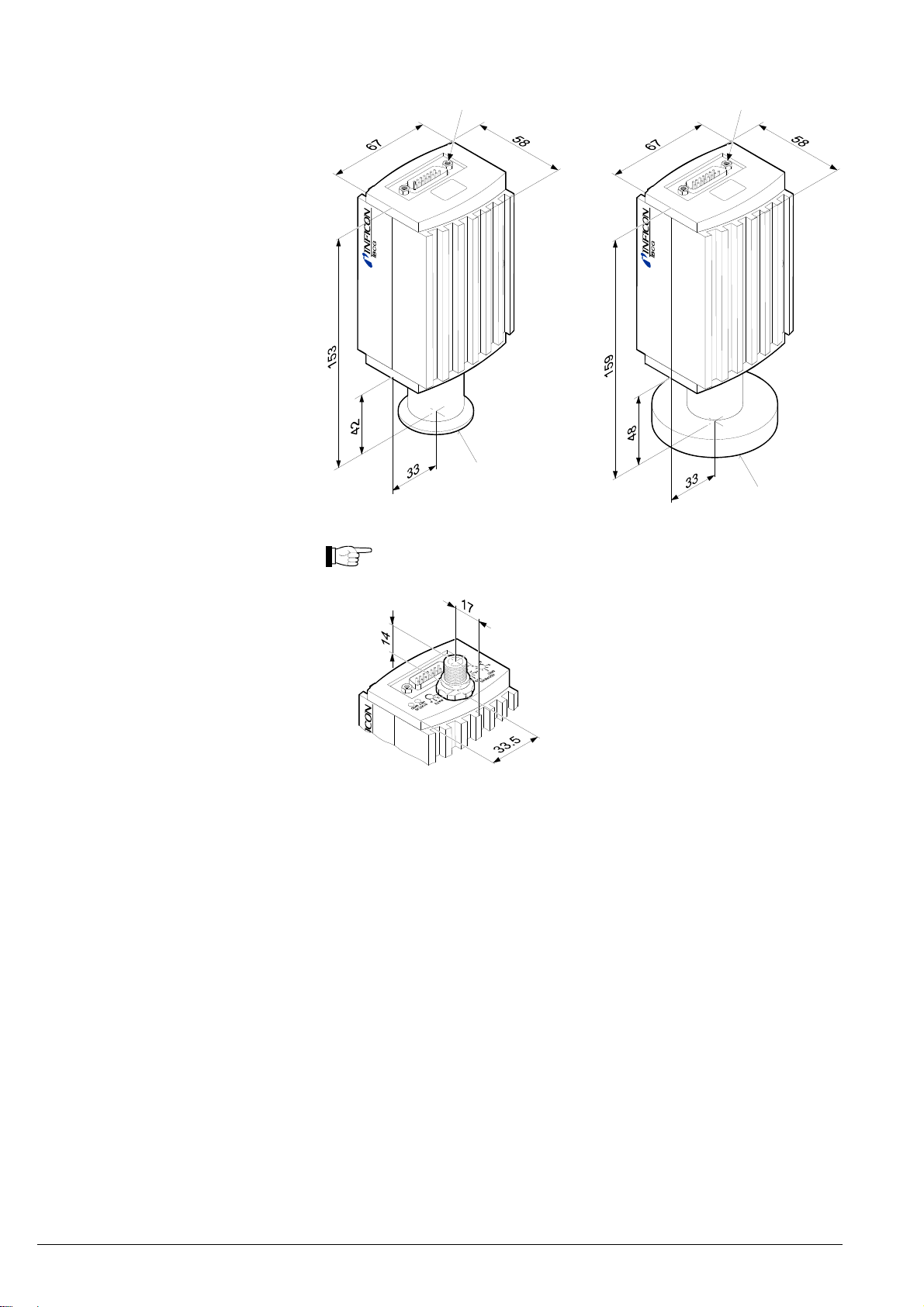
Dimensions [mm]
4-40UNC 2B
4-40UNC 2B
DN 25 ISO-KF
DN 40 CF-R
Weight
Gauges with DeviceNet connector are 14 mm longer.
353-550, 353-552, 353-561
353-551, 353-553
353-554, 353-557, 353-562
353-556, 353-558
≈305 g
≈565 g
≈445 g
≈710 g
12
tina40e1-b (2011-04)
Page 13
3 Installation
3.1 Vacuum Connection
DANGER: overpressure in the vacuum system >1 bar
Injury caused by released parts and harm caused by escaping process
gases can result if clamps are opened while the vacuum system is
pressurized.
Do not open any clamps while the vacuum system is pressurized. Use
the type of clamps which are suited to overpressure.
DANGER: overpressure in the vacuum system >2.5 bar
KF flange connections with elastomer seals (e.g. O-rings) cannot
withstand such pressures. Process media can thus leak and possibly
damage your health.
Use O-rings provided with an outer centering ring.
DANGER
DANGER
The gauge must be electrically connected to the grounded vacuum
chamber. This connection must conform to the requirements of a protective connection according to EN 61010:
• CF connections fulfill this requirement
For gauges with a KF vacuum connection, use a conductive metallic
clamping ring.
Caution: vacuum component
Dirt and damages impair the function of the vacuum component.
When handling vacuum components, take appropriate measures to
ensure cleanliness and prevent damages.
Caution: dirt sensitive area
Touching the product or parts thereof with bare hands increases the
desorption rate.
Always wear clean, lint-free gloves and use clean tools when working
in this area.
DANGER
Caution
Caution
The gauge may be mounted in any orientation. To keep condensates
and particles from getting into the measuring chamber, preferably
choose a horizontal to upright position. See dimensional drawing for
space requirements (→ 12).
• The gauge is supplied with a built-in grid. For potentially contaminating applications and to protect the electrodes against light and fast charged particles, installation (→ 16) of the optional baffle is recommended (→ 50).
• The sensor can be baked at up to 80 °C (at vacuum connection, horizontally
mounted). At temperatures exceeding 50 °C, the electronics unit has to be removed (→ 15).
tina40e1-b (2011-04) 13
Page 14
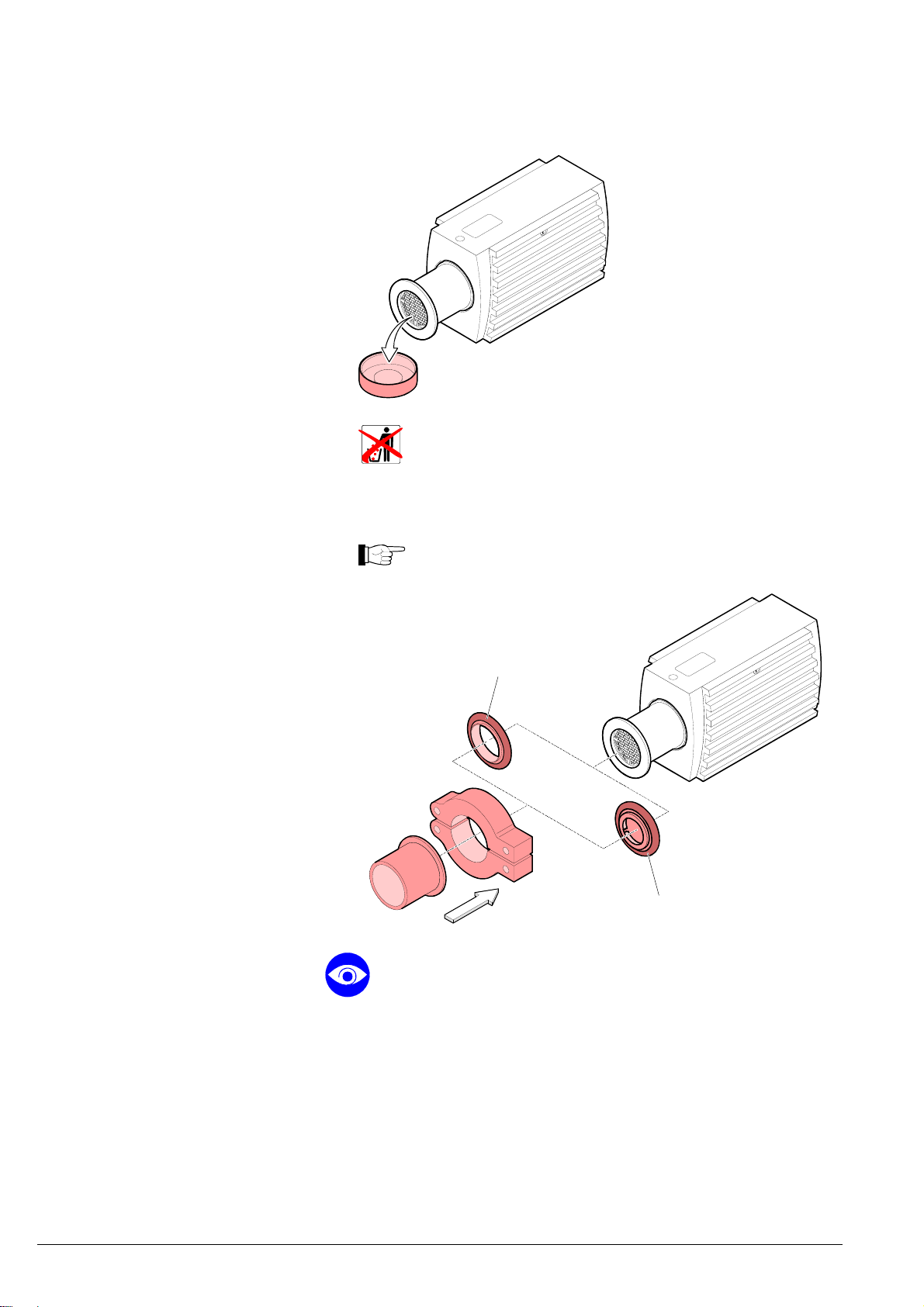
Procedure
Remove the protective lid.
The protective lid will be needed for maintenance..
Make the flange connection to the vacuum system
INFICON recommends to install the gauge without applying vacuum
grease.
Seal with centering ring
or
When installing the gauge, make sure that the area around the con-
nector is accessible for the tools required for adjustment while the gauge
is mounted (→ 41, 45).
When installing the gauge, allow for installing/deinstalling the connectors
and accommodation of cable loops.
If you are using a gauge with display, make sure easy reading of the
display is possible.
14
Seal with centering ring
and baffle (Option)
tina40e1-b (2011-04)
Page 15
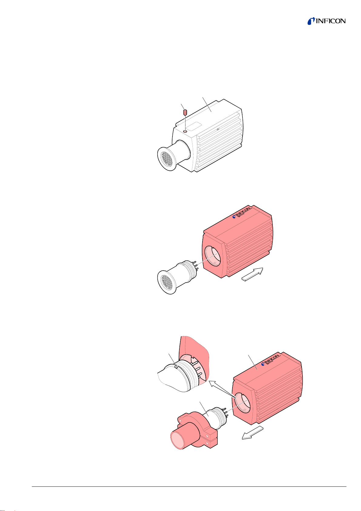
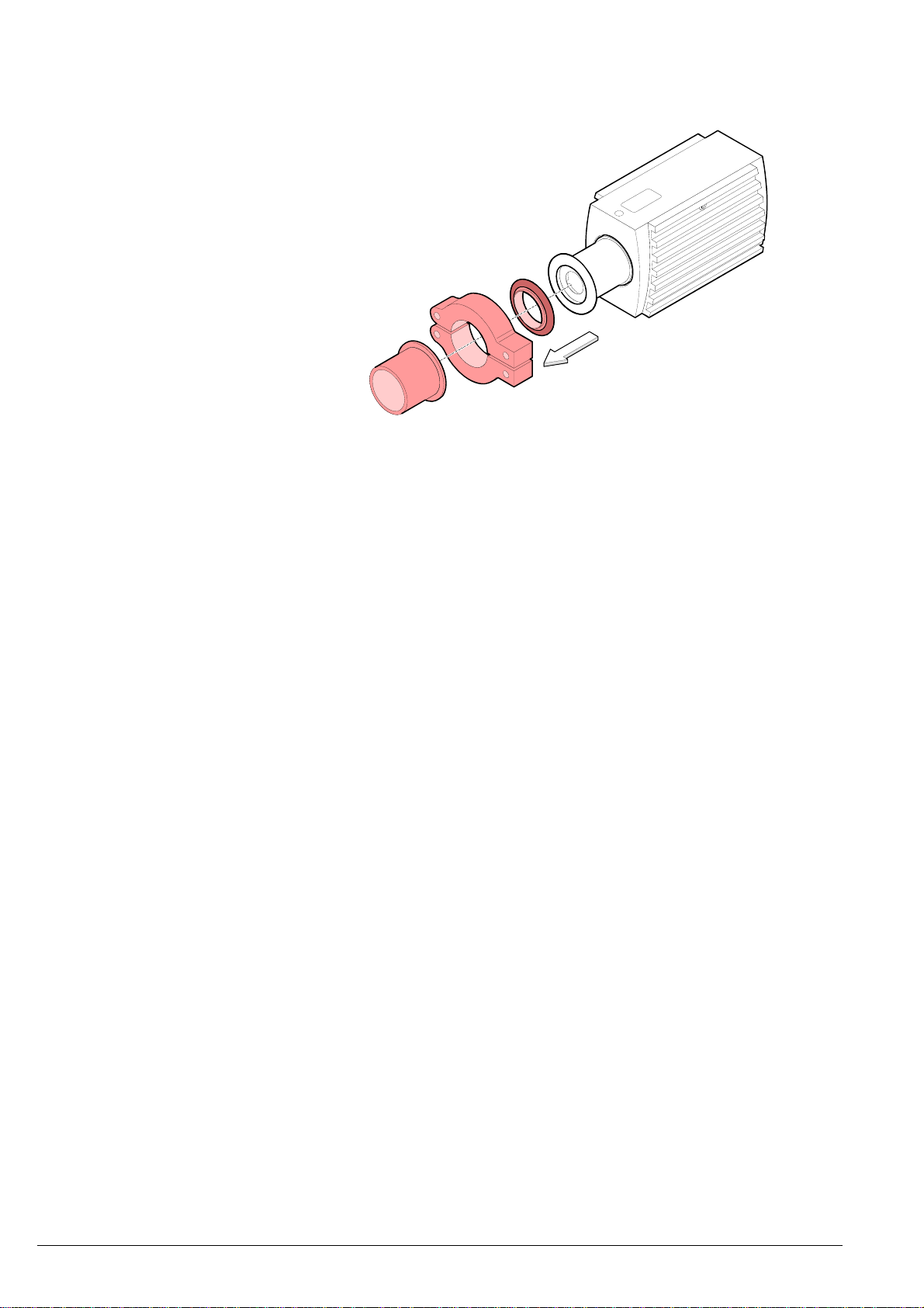
3.1.1 Removing and Installing
the Electronics Unit
Required tools/material
Removing the electronics unit
• Allen key, AF 2.5
Unscrew the hexagon socket set screw (1) on the side of the electronics
unit (2).
2
1
Installing the electronics unit
Remove the electronics unit without twisting it.
Place the electronics unit (2) on the sensor (3) (be careful to correctly align
the pins and notch (4)).
4
3
2
Slide the electronics unit in to the mechanical stop and lock it with the hexa-
gon socket set screw.
tina40e1-b (2011-04) 15
Page 16
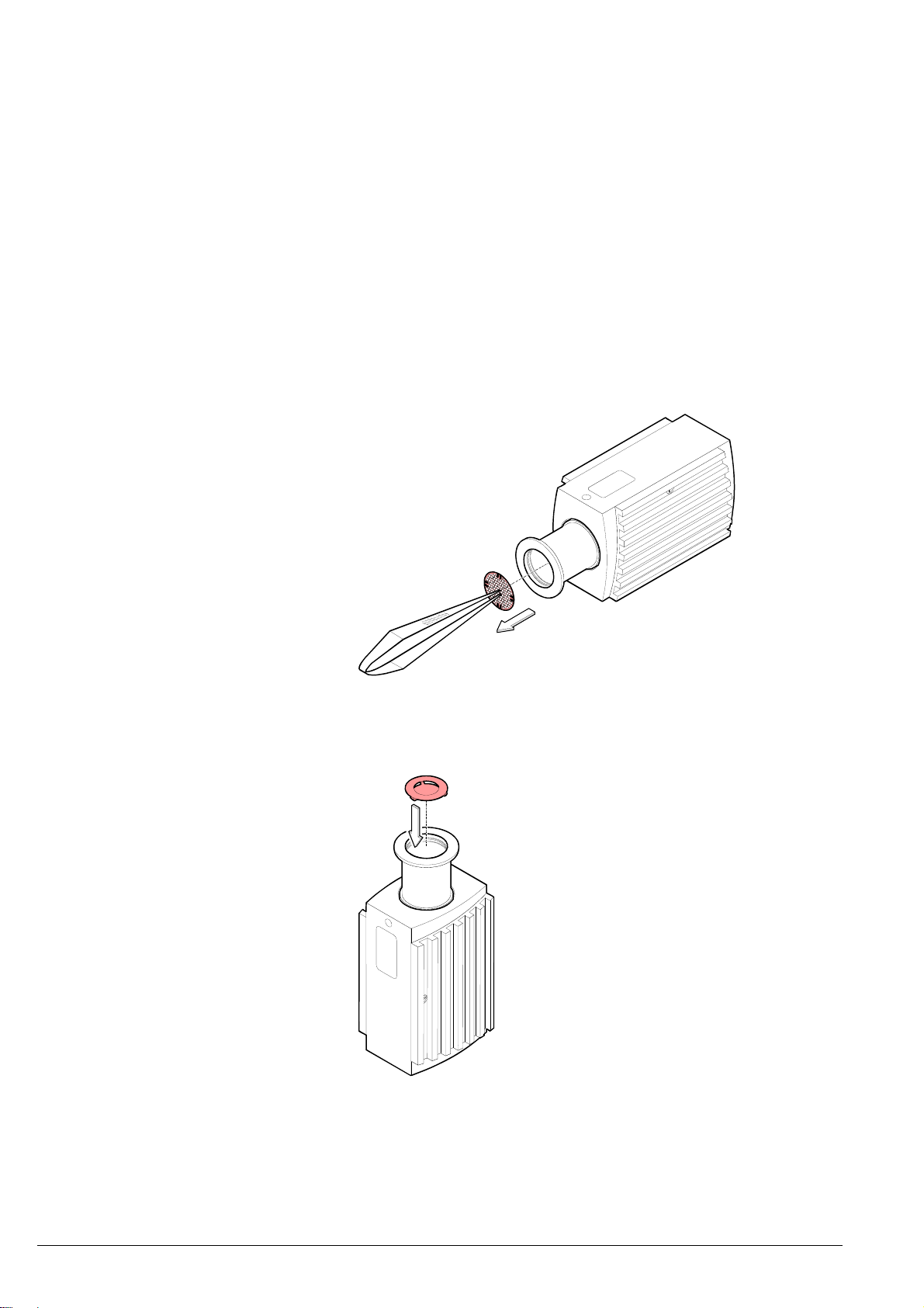
3.1.2 Using the Optional Baffle
Requirement
Required tools / material
Installation
In severely contaminating processes and to protect measurement electrodes optically against light and fast charged particles, replacement of the built-in grid by the
optional baffle (→ 50) is recommended.
The gauge is deinstalled (deinstallation gauge → 43).
• Baffle (→ 50)
• Pointed tweezers
• Pin (e.g. pencil)
• Screwdriver No 1
Carefully remove the grid with tweezers.
Carefully place the baffle onto the sensor opening.
16
tina40e1-b (2011-04)
Page 17
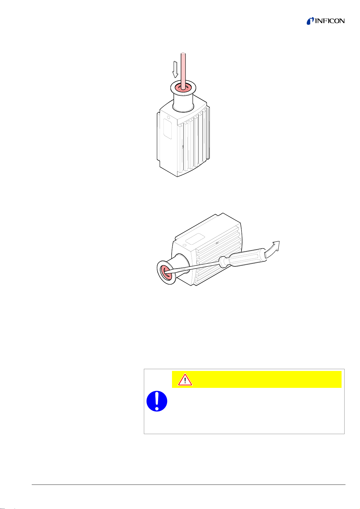
Using a pin, press the baffle down in the center until it catches.
Deinstallation
3.2 Power Connection
3.2.1 Use With INFICON
VGC40x Vacuum Gauge
Controller
Carefully remove the baffle with the screwdriver.
If the gauge is used with an INFICON VGC40x controller, a corresponding sensor
cable is required (→ [3]). The sensor cable permits supplying the gauge with
power, transmitting measurement values and gauge statuses, and making parameter settings.
Caution
Caution: data transmission errors
The attempt to operate a fieldbus gauge (BCG450-SD / -SP) with the
VGC40x Vacuum Gauge Controller (RS232C) causes data transmission errors.
Fieldbus gauges must not be operated with an INFICON VGC40x
Required material
• Sensor cable (→ [3], INFICON sales literature)
tina40e1-b (2011-04) 17
controller.
Page 18
Procedure
Plug the sensor connector into the gauge and secure it with the locking
screws.
Connect the other end of the sensor cable to the INFICON controller and
secure it.
3.2.2 Use With Other
Controllers
3.2.2.1 Making an Individual
Sensor Cable
Cable type
Procedure
The gauge can now be operated with the VGC40x controller.
The gauge can also be operated with other controllers.
Especially the fieldbus versions BCG450-SD (DeviceNet) and BCG450-SP
(Profibus) are usually operated as part of a network, controlled by a master or bus
controller. In such cases, the control system has to be operated with the appropriate software and communication protocol.
For reasons of compatibility, the expression "sensor cable" is used for all
BCG450 versions in this document, although the pressure reading of the
gauges with fieldbus interface (BCG450-SD or BCG450-SP) is normally
transmitted via DeviceNet or Profibus.
The sensor cable is required for supplying all BCG450 types with power.
It also permits access to the relay contacts of the switching functions
(→ 20).
The application and length of the sensor cable have to be considered when determining the number and cross sections of the conductors (→ 9).
Open the cable connector (D-Sub, 15-pin, female).
Prepare the cable and solder/crimp it to the connector as indicated in the
diagram of the gauge used:
18
tina40e1-b (2011-04)
Page 19

Sensor cable connection
BCG450
Atmospheric
pressure
reached
TxD
1
4
13
RS232
Electrical connection
RxD
Degas
Measuring
signal
Common (power GND 24V supply)
Ground (housing, vacuum connection)
-
+
42 k
Ω
14
12
10
15
7
2
Degas
-
15
1.25 AT
Ident.
9
1
D-Sub,15-pin,
female,
soldering side
8
8
5
Pin 1 Relay "Atmosphere reached", n.o. contact
Pin 2 Measuring signal output 0 … +10.13 V
Pin 4 Relay "Atmosphere reached", com contact
Pin 5 Supply common 0 V
Pin 7 Degas on, active high 0 V/+24 V
Pin 8 Supply +24 V
Pin 10 Gauge identification
Pin 12 Measuring signal common
Pin 13 RS232, TxD
Pin 14 RS232, RxD
Pin 15 Do not connect
Pins 3, 6, 9 and 11 are not connected internally.
24V
-
-
tina40e1-b (2011-04) 19
Page 20

Sensor cable connection
BCG450-SD, -SP
-
Threshold values
SP A
SP B
( )
SP A
SP B
2)
2)
11
13
14
1)
3
6
1
4
9
Degas
Measuring
signal
-
+
42 k
Ω
Common (power GND 24V supply)
Ground (housing, vacuum connection)
Electrical connection
Pin 1 Relay switching function A, n.o. contact
12
10
15
7
2
Degas
-
8
5
15
1.25 AT
Ident.
9
1
D-Sub,15-pin,
female,
soldering side
8
2)
Pin 2 Measuring signal output 0 … +10.13 V
Pin 3 Threshold (setpoint) A
Pin 4 Relay switching function A, com contact
1)
2)
Pin 5 Supply common 0 V
1)
Pin 6 Threshold (setpoint) B
0 … +10 V
Pin 7 Degas on, active high 0 V/+24 V
Pin 8 Supply +24 V
2)
Pin 9 Relay switching function B, n.o. contact
Pin 10 Gauge identification
2)
Pin 11 Relay switching function B, com contact
Pin 12 Measuring signal common
Pin 13 Do not connect
Pin 14 Do not connect
Pin 15 Do not connect
1)
Do not connect pin 3 and pin 6 for normal operation of the gauge. These
pins are reserved for adjustment of the setpoint potentiometers
(→ 42).
2)
Relay assignement can be reprogrammed for atmosphere switching
function via serial interfaces (→ 31 and [1] or [2]).
24V
-
-
0 … +10 V
WARNING
Incorrect connection, incorrect polarity or inadmissible supply
voltages can damage the gauge.
20
tina40e1-b (2011-04)
Page 21

For cable lengths up to 5 m (0.34 mm2 conductor cross-section) the out-
put signal can be measured directly between the positive signal output
(Pin 2) and supply common GND (Pin 5). At greater cable lengths, differential measurement between signal output (Pin 2) and signal
common (Pin 12) is recommended.
Reassemble the cable connector.
On the other cable end, terminate the cable according to the requirements of
the gauge controller you are using.
Plug the sensor connector into the gauge and secure it with the locking
screws.
l
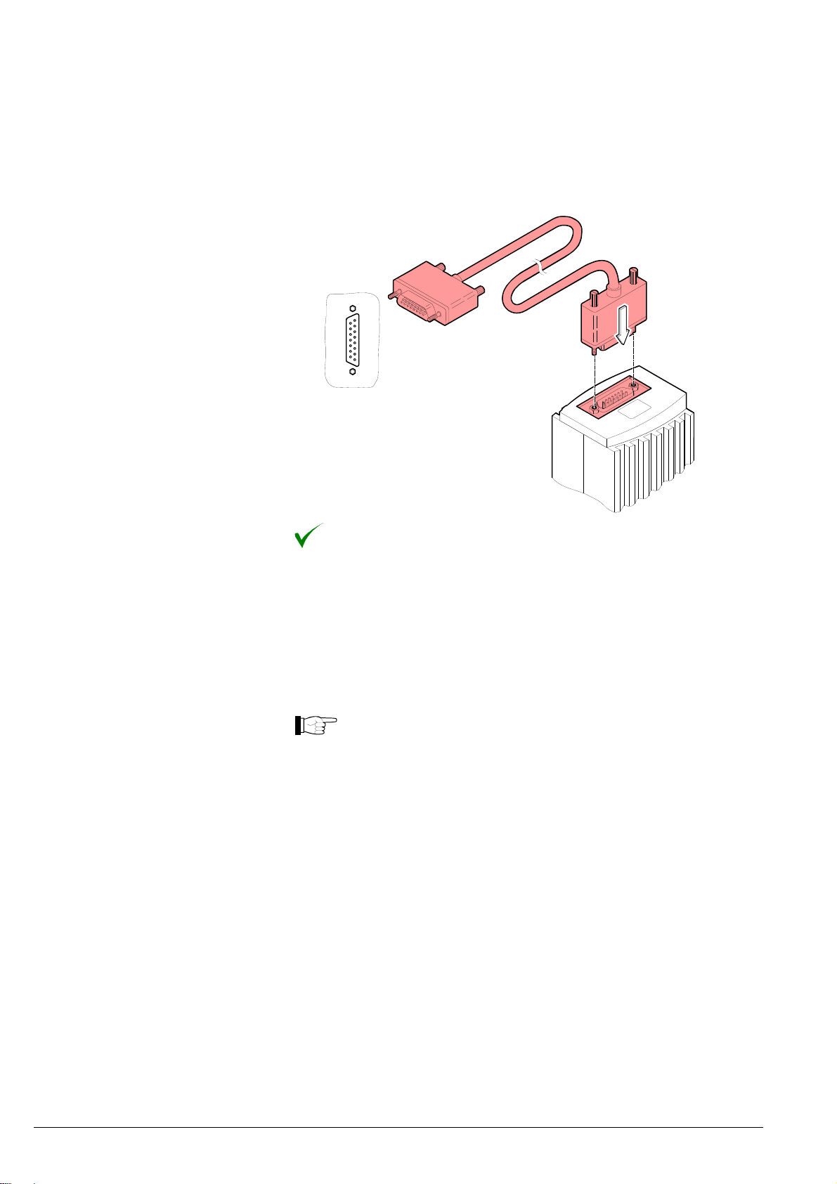
3.2.2.2 Making a DeviceNet
Interface Cable
(BCG450-SD)
Cable type
Procedure
Connect the other end of the sensor cable to the connector of the instrument
or gauge controller you are using.
The gauge can now be operated via analog and RS232C interface.
For operating BCG450-SD via DeviceNet, an interface cable conforming to the
DeviceNet standard is required.
If no such cable is available, make one according to the following indications.
A shielded special 5 conductor cable conforming to the DeviceNet standard has to
be used (→ [4], [6]).
Make the DeviceNet cable according to the following indications.
Pin 1 Drain
Pin 2 Supply +24 VDC (DeviceNet interface only)
Pin 3 Supply common GND (DeviceNet interface only)
Pin 4 CAN_H
Pin 5 CAN_L
1
5
3
Micro-Style, 5-pin,
(DeviceNet)
42
female, soldering side
tina40e1-b (2011-04) 21
Page 22

Plug the DeviceNet (and sensor) cable connector into the gauge.
3.2.2.3 Making a Profibus
Interface Cable
(BCG450-SP)
Cable type
Procedure
Sensor cable
DeviceNet cable
Lock the DeviceNet (and sensor) cable connector.
The gauge can now be operated via DeviceNet interface (→ 38).
For operating BCG450-SP via Profibus, an interface cable conforming to the
Profibus standard is required.
If no such cable is available, make one according to the following indications.
Only a cable that is suited to Profibus operation may be used (→ [5], [7]).
Make the Profibus interface cable according to the following indications:
1 5
D-Sub, 9-pin
male, soldering side
6 9
Pin 1 Do not connect
Pin 2 Do not connect
Pin 3 RxD/TxD-P
Pin 4 CNTR-P
Pin 5 DGND
Pin 6 VP
Pin 7 Not connected internally
Pin 8 RxD/TxD-N
Pin 9 Not connected internally
1)
Only to be connected if an optical link module is used.
2)
Only required as line termination for devices at both ends of bus cable
(→ [5]).
22
1)
2)
2)
tina40e1-b (2011-04)
Page 23

3.2.3 Using the Optional Power
Supply
(With RS232C Line)
Technical data
Plug the Profibus (and sensor) cable connector into the gauge.
Sensor cable
Profibus cable
Lock the Profibus (and sensor) cable connector.
The gauge can now be operated via Profibus interface (→ 40).
The optional 24 V power supply (→ 50) allows RS232C operation of the BCG450
gauge with any suitable instrument or control device.
The instrument or control device needs to be equipped with a software that supports the RS232C protocol of the gauge (→ 33).
Mains connection
Mains voltage 90 … 250 VAC 50 … 60 Hz
Mains cable 1.8 meter (Schuko DIN and U.S. con-
nectors)
Output (operating voltage of gauge, Vs)
Voltage 21 … 27 VDC, set to 24 VDC
Current Max. 1.5 A
Gauge connection
Connector D-Sub, 15-pin, female
24 VDC cable 5 m, black
Connection of the instrument or control
device
RS232C connection D-Sub, 9 pin, female
Cable 5 m, black, 3 conductors, shielded
tina40e1-b (2011-04) 23
Page 24

Wiring diagram
Connecting the power supply
8
7
6
RS232C
4
D-Sub, 9-pin
5
2
3
L
Mains
N
90 ... 250 VAC
PE
50 ... 60 Hz
BCG450
D-Sub,
15-pin
5
13
14
8
15
PE
+24 V
GND
DC
AC
Connect the power supply to the the gauge and lock the connector with the
screws.
Connect the RS232C line to the instrument or control device and lock the
connector with the screws.
RS232C
Power
supply
BCG450
Connect the power supply to the mains.
The gauge can now be operated via RS232C interface (→ 33).
PC
Mains
24
tina40e1-b (2011-04)
Page 25

4 Operation
4.1 Measuring Principle,
Measuring Behavior
Bayard-Alpert (BA)
The BCG450 vacuum gauges consist of three separate measuring systems (hot
cathode Bayard-Alpert (BA) Pirani sensor and capacitance diaphragm sensor).
The BA measuring system uses an electrode system according to Bayard-Alpert
which is designed for a low x-ray limit.
The measuring principle of this measuring system is based on gas ionization. Electrons emitted by the hot cathode (F) ionize a number of molecules proportional to
the pressure in the measuring chamber. The ion collector (IC) collects the thus
generated ion current I
ment instrument. The ion current is dependent upon the emission current I
+
and feeds it to the electrometer amplifier of the measure-
, the
e
gas type, and the gas pressure p according to the following relationship:
+
= Ie × p × C
I
Factor C represents the sensitivity of the gauge head. It is generally specified for
N
.
2
The lower measurement limit is 5×10
To usefully cover the whole range of 5×10
-10
mbar (gauge metal sealed).
-10
mbar … 10-2 mbar, a low emission
current is used in the high pressure range (fine vacuum) and a high emission current is used in the low pressure range (high vacuum). The switching of the emission current takes place at decreasing pressure at approx. 7.2×10
creasing pressure at approx. 3.2×10
BCG450 can temporarily (<2 s) deviate from the specified accuracy.
-5
mbar. At the switching threshold, the
-6
mbar, at in-
Pirani
IC
ECF
+– +–
200V40V
(Degas 250V)
EC
F
IC
Diagram of the BA measuring system
F hot cathode (filament)
IC ion collector
EC anode (electron collector)
Within certain limits, the thermal conductibility of gases is pressure dependent. This
physical phenomenon is used for pressure measurement in the thermal conductance vacuum meter according to Pirani. A self-adjusting bridge is used as measuring circuit (→ schematic). A thin tungsten wire forms the sensor element. Wire
resistance and thus temperature are kept constant through a suitable control circuit. The electric power supplied to the wire is a measure for the thermal conductance and thus the gas pressure. The basic principle of the self-adjusting bridge
circuit is shown in the following schematic.
tina40e1-b (2011-04) 25
Page 26

Schematic
Capacitance diaphragm sensorr
Schematic
V
b
Pirani sensor
The bridge voltage V
is a measure for the gas pressure and is further processed
m
electronically (linearization, conversion).
A capacitance diaphragm sensor consists of a reference vacuum chamber, separated from the measured gas pressure by a diaphragm. The capacitance of a pair
of electrodes attached to the diaphragm and the chamber is measured electronically. A pressure difference acting upon the diaphragm will deflect it and cause a
change of capacitance between the electrodes. A pressure related measuring signal is produced, ready for further processing.
Reference vacuum chamberDiaphragm
Electrodes
Measuring range
Measured gas
pressure
Measuring
signal
Capacitance
measurement
The BCG450 gauges continuously cover the measuring range
-10
5×10
mbar … 1500 mbar.
• The Pirani constantly monitors the pressure.
• The hot cathode (controlled by the Pirani) is activated only at pressures
<2.4×10
-2
mbar.
If the measured pressure is higher than the switching threshold, the hot cathode is
switched off and the Pirani measurement value is output.
-2
If the Pirani measurement drops below the switching threshold (p = 2.4×10
the hot cathode is switched on. After heating up, the measured value of the hot
cathode is fed to the output. In the crossover range of 5.5×10
-3
… 2.0×10⁻² mbar,
mbar),
the output signal is generated from both measurements.
-2
Pressure rising over the switching threshold (p = 3.2×10
mbar) causes the hot
cathode to be switched off. The Pirani measurement value is output.
• Above 10 mbar (up to 1500 mbar) the measurement signal of the capacitance
diaphragm sensor is used.
In the crossover range 1 … 10 mbar a mixture of the Pirani sensor signal and the
capacitance diaphragm sensor signal is processed.
26
tina40e1-b (2011-04)
Page 27

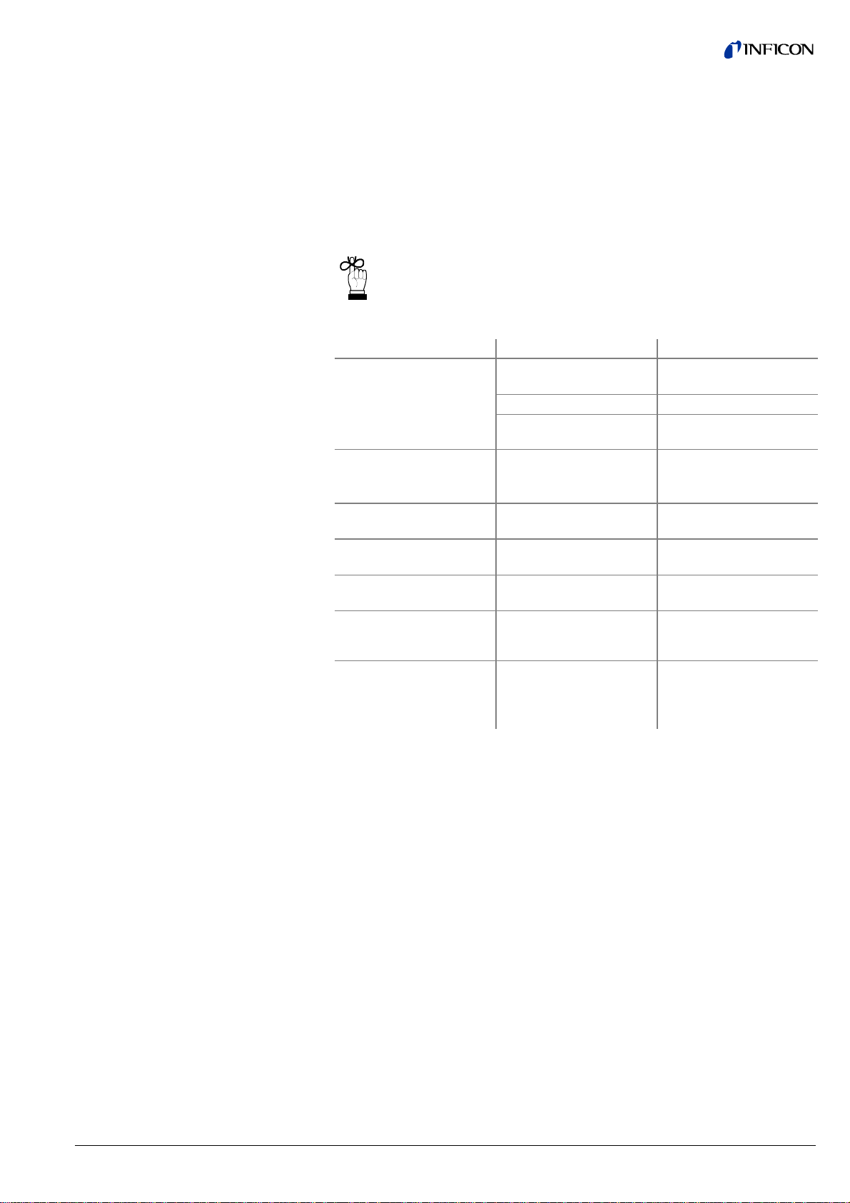
Gas type dependence
4.2 Operational Principle of
the Gauge
Field Bus Versions
(BCG450-SD, BCG450-SP)
Due to the capacitance diaphragm sensor used in the upper pressure range, a
minimized gas type dependence is achieved.
Pressure range Measuring principle Gas type dependence
10 … 1500 mbar
1 … 10 mbar
2×10⁻² … 1 mbar Pirani sensor
5×10⁻³ …
-2
mbar
2×10
-10
5×10
…
-3
5×10
1)
Pressure indicated applies to dry air, O2, CO and N2 and has to be converted
mbar
capacitance diaphragm
sensor
capacitance diaphragm
sensor and Pirani sensor
Pirani sensor and
hot cathode ionisation sensor (BA)
hot cathode ionisation sensor (BA)
independent of gas type,
no correction required
crossover range
1)
crossover range
1)
for other gases (→ Appendix B).
The analog measuring signals of the BA and Pirani sensors are converted into a
digital form by a micro-controller and subsequently converted to a value representing the measured total pressure. After further processing this value is available as
an analog measurement signal (0 … +10.13 V) at the output (sensor cable connector Pin 2 and Pin 12). The maximum output signal is internally limited to
+10.13 V (1500 mbar). The measured value can be read as digital value through
the RS232C interface (only BCG450) (Pins 13, 14 and 5) (→ 33). Gauges with a
display show the value as pressure. The default setting of the displayed pressure
unit is mbar. It can be modified via the RS232C interface (only BCG450) (→ 33).
In addition to converting the output signal, the micro controller's functions include
monitoring of the emission, calculation of the total pressure based on the measurements of the three sensors, and communication via RS232C interface (only
BCG450).
With the built-in atmoshere switching function an atmospheric pressure threshold
can be programmed. If the pressure rises above this value a (semi conductor) relay
"atmospheric pressure reached" is activated. The thresold can be programmed by
the user as a percentage of the actual atmospheric pressure (ambient).
These gauges can be used in a network together with other equipment meeting the
respective standards. Technical data, interface and communication is described in
separate sections (→ 38 for DeviceNet and 40 for Profibus).
Two adjustable switching functions are integrated in the gauge. The corresponding
relay contacts are available at the sensor cable connector (→ 8, 20, 41).
The basic sensor and sensor electronics of all BCG450 versions are identical.
tina40e1-b (2011-04) 27
Page 28

4.3 Putting the Gauge Into
Operation
4.4 Degas
Contamination
When the operating voltage is supplied (→ Technical Data), the output signal is
available between Pin 2 (+) and Pin 12 (–) of the sensor cable connector
(Relationship Output Signal – Pressure → Appendix A).
Allow for a stabilizing time of approx. 10 min. Once the gauge has been switched
on, permanently leave it on irrespective of the pressure.
Communication via the digital interfaces is described in separate sections of this
document.
Gauge failures due to contamination or wear and tear, as well as
expendable parts (e.g. filament), are not covered by the warranty.
Deposits on the electrode system of the BA sensor can lead to unstable measurement readings.
The degas process allows in-situ cleaning of the electrode system by heating the
electron collector grid to approx. 700 °C by electron bombardment.
Depending on the application, this function can be activated by the system control
via one of the gauges digital interfaces. The BCG450 automatically terminates the
degas process after 3 minutes, if it has not been stopped before.
The degas process should be run at pressures below 7.2×10⁻⁶ mbar
(emission current 5 mA).
For a repeated degas process, the control signal first has to change from On
(+24 V) to Off (0 V), to then start degas again with a new On (+24 V) command. It
is recommended that the degas signal be set to Off again by the system control
after 3 minutes of degassing, to achieve an unambiguous operating status.
A new degas cycle can only be started after a waiting time of
30 minutes.
28
tina40e1-b (2011-04)
Page 29

4.5 Emission Control Mode
General
The emission control mode function defines the rules by which the emission of the
gauge is switched on and off.
The manual mode feature has a positive effect on gauge live time, mainly in process situations where the process chamber has to be vented frequently.
Emission Control Mode Description
• Automatic (AUTO)
• Manual (MAN)
The emission control mode parameter is only accessible via the serial
interfaces and described in the respective sections (→ 33, [1] and
[2]).
(Switching the emission on/off via RS232 → 37)
By default, the automatic mode is active and the emission is switched on and off automatically by the gauge.
However, the emission will only be switched on if the
pressure falls below "Switching on pressure" (→ 8).
If the pressure rises above the "Switching off pressure"
(→ 8) the emission is switched off. However, the
user can switch off the emission any time via the interfaces (→ below).
If the emission is switched off manually while it is in the
on state, it is switched on again only after pressure has
exeeded "Switching off pressure" and subsequently
fallen below "Switching on pressure".
In manual mode, the emission can be switched on and
off by the user. However, switching on the emission is
only possible if the pressure is below "Switching on
pressure" (→ 8). If the pressure rises above the
"Switching off pressure" (→ 8) while the emission is
on, the emission will be switched off by the gauge.
tina40e1-b (2011-04) 29
Page 30
4.6 Atmosphere Switching
Function
4.6.1 Functional Principle
The Atmosphere Switching Function is used to define an atmospheric pressure
threshold where a (semiconductor) relay "Atmospheric pressure reached" is activated or deactivated 1).
The atmospheric pressure threshold is user programmable as a percentage of the
ambient atmospheric pressure (100%)
2)
.
A separate sensor built into the gauge (measuring ambient atmospheric pressure )
is used as a reference.
The following rule applies:
Atmospheric pressure threshold =
Atmospheric pressure × N
—————————————
100
where:
Atmospheric pressure threshold
Atmospheric pressure
N [%] : User programmable percentage value
[mbar] : If chamber pressure rises above this value, the
"Atmospheric pressure reached" relay is activa-
3)
ted
[mbar] : Ambient atmospheric pressure (100%)
(measured outside the vacuum chamber)
2)
(admissible range: 1 … 140%
, default = 99%)
The measuring range of the gauge is limited to 1500 mbar. If the calcu-
lated atmospheric pressure threshold exceeds 1500 mbar, the relay will
never be activated. Keep this in mind when choosing N.
It is possible to calibrate the atmospheric pressure sensor (→ 45).
1)
Depending on gauge version, access to "Atmospheric pressure reached" relay
contacts differ:
BCG450: A hard wired (semiconductor) relay contact is available
between pins 1 and 4 at the sensor cable connector (→ 19
and 32).
BCG450-SD/SP: The function of the setpoint relays SP A/B (→ 20) can be
reprogrammed to perform as "Atmospheric pressure
reached" relays. Reprogramming is carried out via fieldbus.
(further information → [1] or [2]).
(Default setting: relays are assigned to (SP A / B) setpoints)
2)
Programming of the percentage N can only be carried out via the serial inter-
faces (RS232, DeviceNet or Profibus, → 33, [1] or [2]).
3)
A fixed hysteresis of 2% of the atmospheric pressure threshold is programmed
(→ example below).
30
tina40e1-b (2011-04)
Page 31

Example
The following diagram shows the functional principle using example values
(italic = example values):
Measuring signal
(Pressure p)
4.6.2 Programming the
Atmospheric Pressure
Threshold
Programming via RS232
1500 mbar
980 mbar
833 mbar
Upper limit of measuring range of gauge
Atmospheric pressure (100%, ambient)
u
l
a
v
d
e
r
u
Atmospheric pressure
threshold (85%)
s
a
e
M
2)
e
816 mbar
Hysteresis
(2% of atmospheric
pressure threshold)
Relay status "Atmospheric pressure reached"
Programming the atmospheric pressure threshold can only be carried out via the
serial interfaces.
The relevant parameter: percentage of atmospheric pressure (N) is sent to the
gauge in a 5 byte long command string (general information on RS232 interface
→ 33):
Byte No. Function Value Comment
0 Length of data string 0x03 hex set value
1 Data 0x11 hex
2 Data 0x10 hex
3 Data 0x01 … 0x8C hex 1)
4 Check sum
(of bytes No. 1 … 3)
1)
Admissible range of percentage value (N):
0x01
… 0x8C
hex
hex
= 1
dec
Example:
Atmospheric pressure = 1000 mbar (example)
0x00 … 0xFF hex low byte of sum, high
byte is ignored
… 140
= 1% … 140% (default = 99%).
dec
2)
N = 99% (default)
Hysteresis = 2% (fixed)
⇒ Atmospheric pressure threshold = 990 mbar
⇒ If the pressure exceeds 990 mbar, the relay "Atmosphere reached". is
activated. As the pressure drops below 970 mbar, the relays is deactivated.
2)
It is possible to calibrate the atmospheric pressure sensor (→ 45).
Programming via fieldbus
interfaces
The definition of the function assigned to the relays (SP A/B or "Atmospheric pressure reached") and the value "Percentage of atmospheric pressure" (N) is described in the communication protocol of the respective interface version (for
DeviceNet → [1], for Profibus → [2]).
tina40e1-b (2011-04) 31
Page 32

A
4.6.3 Wiring the relay
"Atmospheric Pressure
Reached"
(BCG450)
The signal: atmospheric pressure reached is made available via a floating n. o.
contact of a photo MOS relay contact at the sensor cable connector (→ 19)
Specifications of the n. o. contact:
Load voltage (VL) ≤30 V AC/DC
2)
Load current ≤300 mA AC/DC
tmospheric pressure
reached
1
1)
.
4.7 Display (BCG450)
Pressure Display
4
Sensor cable
2)
R
V
CL
2)
U
L
connector
Load
Diode
1)
Contact specifications for fieldbus gauges BCG450-SD/SP can be found in the
section: Technical Data since the (reprogrammed) setpoint relays (SP A/B) are
used (→ 20, [1] or [2]).
2)
In case of capacitive loads, the charging current has to be limited to the max.
current value specified above (e.g. using a current limiting resistor R
).
v
For inductive loads, voltage peaks have to be suppressed by a parallel diode as
shown. To minimize inductance, keep the wiring as short as possible.
The gauges with part number
353-552 and
353-553
have a built-in two-line display with an LCD matrix of 32×16 pixels. The first line
shows the pressure, the second line the pressure unit, the function and possible
errors. The background illumination is usually green, in the event of an error, it
changes to red. The pressure is displayed in mbar (default), Torr or Pa. The pressure unit can be changed via RS232C interface (→ 33).
Pressure reading
Pressure unit
Function Display
Function display
32
(none)
Pirani operation
E Emission 25 μA
. Emission 5 mA
E
D Degas
tina40e1-b (2011-04)
Page 33

Error Display
No error
(green background illumination)
Pirani sensor error
(red background illumination)
BA sensor error
(red background illumination)
Diaphragm sensor error
(red background illumination)
EEPROM error
(red background illumination)
Internal data connection failure
(red background illumination)
4.8 RS232C Interface
What to do in case of problems → 47.
The built-in RS232C interface allows transmission of digital measurement data and
instrument conditions as well as the setting of instrument parameters.
Caution
Caution: data transmission errors
The attempt to operate a fieldbus gauge (BCG450-SD / -SP) with the
RS232C interface causes data transmission errors.
Fieldbus gauges must not be operated with the RS232C interface.
tina40e1-b (2011-04) 33
Page 34

4.8.1 Description of the
Functions
Operational parameters
Electrical connections
4.8.1.1 Output String (Transmit
Format of the output string
Synchronization
The interface works in duplex mode. A nine byte string is sent continuously without
a request approx. every 20 ms.
Commands are transmitted to the gauge in a five byte input (receive) string.
• Data rate
• Byte
9600 Baud set value, no handshake
8 data bits
1 stop bit
• TxD
• RxD
• GND
Pin 13
Pin 14
Pin 5
(Sensor cable connector)
)
The complete output string (frame) is nine bytes (byte 0 … 8). The data string is
seven bytes (byte 1 … 7).
Byte No. Function Value Comment
0 Length of data string 7 set value
1 Page number 5 for BCG450
2 Status
3 Error
4 Measurement high byte 0 … 255
5 Measurement low byte 0 … 255
6 Software version 0 … 255
→ Status byte
→ Error byte
→ Calculation of pressure value
→ Calculation of pressure value
→ Software version
7 Response value 13 for BCG450
8 Check sum 0 … 255
Synchronization of the master is achieved by testing three bytes:
→ Synchronization
Byte No. Function Value Comment
0 Length of data string 7 set value
1 Page number 5 for BCG450
8 Check sum of bytes 1 … 7 0 … 255 Low byte of check
1)
High order bytes are ignored in the check sum.
sum
1)
34
tina40e1-b (2011-04)
Page 35

Status byte
Error byte
Software version
Calculation of the pressure
value
Bit 1 Bit 0 Definition
0 0 emission off
0 1
emission 25 μA
1 0 emission 5 mA
1 1 degas
Bit 2 Definition
x reserved for future use
x reserved for future use
Bit 3 Definition
0 ⇔ 1
toggle bit, changes with every
string received correctly
Bit 5 Bit 4 Definition
0 0 current pressure unit mbar
0 1 current pressure unit Torr
1 0 current pressure unit Pa
Bit 7 Bit 6 Definition
x x reserved for future use
Bit No. Definition
Message on display
(only BCG450 353-552
and 353-553)
0 diaphragm sensor error "FAIL Cap"
1 reserved for future use —
2 Pirani sensor error "FAIL Pir"
3 reserved for future use —
4 BA sensor error "FAIL Ion"
5 reserved for future use —
6 hardware failure, EEPROM failure "FAIL EL"
7 reserved for future use —
The software version of the gauge can be calculated from the response value of
byte 6 of the transmitted string according to the following rule:
Version No = Value
(Example: According to the above formula, Value
Byte 6
/ 20
of 32 means software ver-
Byte 6
sion 1.6)
The pressure can be calculated from bytes 4 and 5 of the transmitted string. Depending on the currently selected pressure unit (→ byte 2, bits 4 and 5), the appropriate rule must be applied.
As result, the pressure value results in the usual decimal format.
p
mbar
p
Torr
p
= 10
Pa
= 10
((high byte × 256 + low byte) / 4000 - 12.5)
= 10
((high byte × 256 + low byte) / 4000 - 12.625)
((high byte × 256 + low byte) / 4000 - 10.5)
tina40e1-b (2011-04) 35
Page 36

Example
4.8.1.2 Input String (Receive)
Format of the input string
The example is based on the following output string:
Byte No. 0 1 2 3 4 5 6 7 8
Value 7 5 0 0 242 48 20 13 69
The instrument or controller (receiver) interprets this string as follows:
Byte No. Function Value Comment
0 Length of data
7 set value
string
1 Page number 5 BCG450
2 Status 0
Emission = off
Pressure unit = mbar
3 Error 0
Measurement
4
5
High byte
Low byte
6 Software version 20
No error
Calculation of the pressure:
242
48
((242 × 256 + 48) / 4000 - 12.5)
p = 10
Software version = 20 / 20 = 1.0
= 1000 mbar
7 Sensor type 13 BCG450
8 Check sum 69
5 + 0 + 0 + 242 + 48 + 20 + 13 =
328
= 01 48
dec
hex
High order byte is ignored ⇒
= 72
Check sum = 48
hex
dec
For transmission of the commands to the gauge, a string (frame) of five bytes is
sent (without <CR>). Byte 1 to byte 3 form the data string.
Byte No Function Value Comment
0 Length of data string 3 set value
1 Data
2 Data
3 Data
4 Check sum
1)
High order bytes are ignored in the check sum.
(of bytes No 1 … 3) 0 … 255
→ admissible input strings
→ admissible input strings
→ admissible input strings
(low byte of sum)
1)
36
tina40e1-b (2011-04)
Page 37

Admissible input strings
For commands to the gauge, six defined strings are used:
Byte No.
Command: 0 1 2 3 4
2)
Set the unit mbar on the display 1) 3 0x10 0x8E 0 0x9E
Set the unit Torr on the display 1) 3 0x10 0x8E 1 0x9F
Set the unit Pa on the display 1) 3 0x10 0x8E 2 0xA0
Storage of current unit 3) 3 0x20 0x07 - 0x27
Switch degas on (switches itself off after 3 min.) 3 0x10 0xC4 1 0xD5
Switch degas off (before 3 min.) 3 0x10 0xC4 0 0xD4
Read software version 4) 3 0x00 0xD1 - 0xD1
Reset 3 0x40 0 0 0x40
Switch emission on 5) 3 0x40 0x10 1 0x51
Switch emission off 5) 3 0x40 0x10 0 0x50
Emission Control Mode automatic (AUTO) 6) 3 0x10 0x8A 1 0x8B
Emission Control Mode manual (MAN) 6) 3 0x10 0x8A 0 0x8A
1)
Only required for gauges with display (353-552 and 353-553). Transmitted data
is not affected by this setting.
2)
Only low order byte of sum (high order byte is ignored).
3)
Current unit is stored in power-failure-safe NV RAM.
4)
Response value in byte no. 6 of transmitted string.
5)
On/off switching requirements → 29.
6)
Defines the Emission Control Mode (→ 29)
AUTO = emission on/off automatically controlled by the gauge
MAN = emission on/off controlled via interfaces
tina40e1-b (2011-04) 37
Page 38

4.9 DeviceNet Interface
(BCG450-SD)
4.9.1 Description of the
Functions
4.9.2 Operating Parameters
4.9.2.1 Operating Software
4.9.2.2 Node Address Setting
This interface allows operation of BCG450-SD with part number
353-557,
353-558 and
353-562
in connection with other devices that are suited for DeviceNet operation. The
physical interface and communication firmware of BCG450-SD comply with the
DeviceNet standard (→ [4], [6]).
Two adjustable switching functions are integrated in BCG450-SD. The corresponding relay contacts are available at the sensor cable connector
(→ 8, 20, 41).
The basic sensor and sensor electronics of all BCG450 gauges are identical.
Caution
Caution: data transmission errors
The attempt to operate the BCG450-SD with the RS232C interface
causes data transmission errors.
Via this interface, the following and further data are exchanged in the standardized
DeviceNet protocol (→ [1]):
• Pressure reading
• Pressure unit (Torr, mbar, Pa)
• Degas function
• Status and error messages
• Status of the switching functions
As the DeviceNet protocol is highly complex, the parameters and programming of
BCG450-SD are described in detail in the separate Communication Protocol
(→ [1]).
Before the gauge is put into operation, it has to be configured for DeviceNet operation. A configuration tool and the device specific EDS file (Electronic Data
Sheet) are required for this purpose. The EDS file can be downloaded via internet
(→ [3]).
For unambiguous identification of the gauge in a DeviceNet environment, a node
address is required. The node address setting is made on the gauge or programmed via DeviceNet.
The BCG450-SD must not be operated with the RS232C interface.
Set the node address (0 … 63
) via the "ADDRESS" "MSD"
dec
and "LSD" switches. The node address is polled by the firmware
when the gauge is switched on. If the setting deviates from the
stored value, the new value is taken over into the NVRAM. If a
setting higher than 63 is made, the previous node address setting remains valid.
Default address setting is 63
dec
.
If the „MSD“ switch is in the "P" position, the node address is
programmable via DeviceNet (→ [1]).
38
tina40e1-b (2011-04)
Page 39

4.9.2.3 Data Rate Setting
4.9.3 Status Lights
"STATUS MOD"
(gauge status):
"STATUS NET"
(network status):
Electrical connections
The admissible data rate depends on a number of factors such as system parameters and cable length → [4], [6]). It can be set on the gauge or pro-
grammed via DeviceNet.
By means of the "RATE" switch, the data rate can be set to 125
("1"), 250 ("2") or 500 kBaud ("5").
If the switch is in any of the "P" positions, the data rate is programmable via DeviceNet (→ [1]).
Two lights (LEDs) on the gauge inform on the gauge status and the current
DeviceNet status.
Light status Description
Dark No supply
Flashing
Selftest
red/green
Green Normal operation
Red Non recoverable error
Flashing red Recoverable error (e.g.
missing DeviceNet power
supply
Light status Description
Dark Gauge not online:
− Selftest not yet concluded
− No supply, → "STATUS MOD" light
Flashing
green
Gauge online but no communication:
− Selftest concluded but no communication to other nodes
established
− Gauge not assigned to any master
Green Gauge online; necessary connections established
Flashing red One or several input/output connections in "time out" status
Red Communication error. The gauge has detected an error that im-
pedes communication via the network (e.g. two identical node addresses (MAC IC) or "Bus-off")
The gauge is connected to the DeviceNet system via the 5-pin DeviceNet connector (→ 21).
tina40e1-b (2011-04) 39
Page 40

4.10 Profibus Interface
(BCG450-SP)
4.10.1 Description of the
Functions
4.10.2 Operating Parameters
4.10.2.1 Operating Software
4.10.2.2 Node Address Setting
Electrical connections
This interface allows operation of BCG450-SP with part number
353-554 and
353-556
in connection with other devices that are suited for Profibus operation. The physical
interface and communication firmware of BCG450-SP comply with the Profibus
standard (→ [7], [5].
Two adjustable switching functions are integrated in the BCG450-SP. The corresponding relay contacts are available at the sensor cable connector
(→ 8, 20, 41).
The basic sensor and sensor electronics of all BCG450 gauges are identical.
Caution
Caution: data transmission errors
The attempt to operate the BCG450-SP with the RS232C interface
causes data transmission errors.
Via this interface, the following and further data are exchanged in the standardized
Profibus protocol (→ [2]):
• Pressure reading
• Pressure unit (Torr, mbar, Pa)
• Degas function
• Status and error messages
• Status of the switching functions
As the DeviceNet protocol is highly complex, the parameters and programming of
BCG450-SP are described in detail in the separate Communication Protocol
(→ [2]).
For operating the gauge via Profibus, prior installation of the BCG450 specific GSD
file is required on the bus master side. This file can be downloaded via internet
(→ [3]).
For unambiguous identification of the gauge in a Profibus environment, a node
address is required. The node address setting is made on the gauge.
The gauge is connected to Profibus via the 9-pin Profibus connector (→ 22).
The BCG450-SP must not be operated with the RS232C interface.
The node address (0 … 125
(00 … 7D
) via the "ADDRESS", "MSD", and "LSD" switches.
hex
) is set in hexadecimal form
dec
The node address is polled by the firmware when the gauge is
switched on. If the setting deviates from the stored value, the
new value is taken over into the NVRAM. If a value >7D
(>125
) is entered, the node address setting currently stored
dec
hex
in the device remains valid but it can now be defined via
Profibus ("Set slave Address", → [2]).
Default address setting is 5C
hex
.
40
tina40e1-b (2011-04)
Page 41

4.11 Switching Functions
(BCG450-SD, -SP)
The gauges BCG450-SD and BCG450-SP have two independent, manually settable switching functions. Each switching function has a floating normally open relay
contact 1). The relay contacts are accessible at the sensor cable connector
(→ 20).
The threshold values of switching functions A and B can be set within the pressure
range 1×10
-9
mbar … 1000 mbar via potentiometers "SETPOINT A" and
"SETPOINT B".
U
Threshold
= 0.75 × (log p
Setpoint
– c) + 7.75
where constant c is pressure unit dependent (→ Appendix A).
Measuring signal
(Pressure p)
e
u
l
a
v
d
e
r
u
s
a
e
(Setpoint A, B)
M
Hysteresis
10% U
Threshold
U
Threshold
4.11.1 Setting the Switching
Functions
Required tools
Switching function
Off
On
Off
Time t
The hysteresis of the switching functions is 10% of the threshold setting.
1)
Both setpoint relays (SP A/B, → 20) can be reprogrammed by the user to
work as atmosphere switching function relays (→ 30 and [1] or [2])
(SP A/B = default setting).
The threshold values of the two switching functions "SETPOINT A" and
"SETPOINT B" are set locally on the potentiometers of the gauge that are accessible via the openings on one side of the gauge housing.
• Voltmeter
• Ohmmeter or continuity checker
• Screwdriver, max. ø2.5 mm
tina40e1-b (2011-04) 41
Page 42

Procedure
The procedure for setting thresholds is identical for both switching functions.
Put the gauge into operation.
Connect the + lead of a voltmeter to the threshold measurement point of the
selected switching function ("Setpoint A" Pin 3, "Setpoint B" Pin 6) and
its – lead to a ground contact nearby (eg. grounded locking screw nut of
connector or vacuum connection of the gauge).
The threshold voltages are referenced to ground (housing,
vacuum connection), not to Pin 5 (common power GND 24 V
supply).
( )
max. ø2.5
Setpoint A Pin 3
Setpoint
Pin 6
B
Using a screwdriver (max. ø2.5 mm), set the voltage of the selected
switching function (Setpoint A, B) to the desired value U
Setting of the switching functions is now concluded.
There is no local visual indication of the statuses of the switching func-
tions. However, a functional check of the switching functions (On/Off)
can be made with one of the following methods:
• Reading the status via fieldbus interface → [1] for BCG450-SD,
→ [2] for BCG450-SP.
• Measurement of the relay contacts at the sensor cable connector
with a ohmmeter/continuity checker (→ 20).
Threshold
.
42
tina40e1-b (2011-04)
Page 43

5 Deinstallation
DANGER: contaminated parts
Contaminated parts can be detrimental to health and environment.
Before beginning to work, find out whether any parts are contaminated. Adhere to the relevant regulations and take the necessary
precautions when handling contaminated parts.
Caution: vacuum component
Dirt and damages impair the function of the vacuum component.
When handling vacuum components, take appropriate measures to
ensure cleanliness and prevent damages.
DANGER
Caution
Caution
Procedure
Caution: dirt sensitive area
Touching the product or parts thereof with bare hands increases the
desorption rate.
Always wear clean, lint-free gloves and use clean tools when working
in this area.
Vent the vacuum system.
Before taking the gauge out of operation, make sure that this has
no adverse effect on the vacuum system.
Depending on the programming of the superset controller, faults
may occur or error messages may be triggered.
Follow the appropriate shut-down and starting procedures.
Take gauge out of operation.
Disconnect all cables from the gauge.
tina40e1-b (2011-04) 43
Page 44
Remove gauge from the vacuum system and replace the protective lid.
44
tina40e1-b (2011-04)
Page 45
6 Maintenance, Repair
6.1 Maintenance
6.1.1 Cleaning the Gauge
DANGER
DANGER: contaminated parts
Contaminated parts can be detrimental to health and environment.
Before beginning to work, find out whether any parts are contaminated. Adhere to the relevant regulations and take the necessary
Small deposits on the electrode system can be removed by baking the anode
(Degas → 28). In the case of severe contamination, the baffle can be exchanged
easily (→ 16). The sensor itself cannot be cleaned and needs to be replaced in
case of severe contamination (→ 49).
A slightly damp cloth normally suffices for cleaning the outside of the unit. Do not
use any aggressive or scouring cleaning agents.
precautions when handling contaminated parts.
6.2 Adjusting the Gauge
6.3 Adjusting the
Atmosphere Sensor
Make sure that no liquid can penetrate the product. Allow the product to
dry thoroughly before putting it into operation again.
Gauge failures due to contamination or wear and tear, as well as
expendable parts (e.g. filament), are not covered by the warranty.
The gauge is factory-calibrated. Through the use in different climatic conditions,
fitting positions, aging or contamination (→ 28) and after exchanging the sensor
(→ 49) a shifting of the characteristic curve can occur. However, readjustments
are automatically carried out during operation of the gauge.
The ambient atmospheric pressure of the gauge is measured by a separate sensor
built into the electronics unit of the gauge (outside the vacuum chamber).
This sensor can be calibrated against the Capacitance Diaphragm sensor in the
gauge. While the gauge is in a vented state, the gauge electronics compares the
output signals of the two sensors and carries out the necessary adjustments to the
atmospheric pressure sensor signal.
The following adjustment procedure can only be carried out via the
serial interfaces.
Adjustment via RS232 interface
(BCG450)
tina40e1-b (2011-04) 45
Vent vacuum system (or operate gauge in the deinstalled state)
Page 46

Two 5 byte long command strings have to be sent to the gauge in succes-
sion (general RS232 information → 33):
String No. 1 (Unlock atmosphere sensor adjustment):
Byte No. Function Value Comment
0 Length of data string 0x03 hex set value
1 Data 0x10 hex
2 Data 0x1C hex
3 Data 0x00 hex
4 Check sum
(of bytes No. 1 … 3)
String No. 2 (execute sensor adjustment):
Byte No. Function Value Comment
0 Length of data string 0x03 hex set value
1 Data 0x40 hex
2 Data 0x20 hex
3 Data 0x01 hex
4 Check sum
(of bytes No. 1 … 3)
0x2C hex low byte of sum, high
byte is ignored
0x61 hex low byte of sum, high
byte is ignored
After the conclusion of this procedure, the separate atmospheric pressor
sensor is calibrated to match the Capacitance Diaphragm sensor.
46
tina40e1-b (2011-04)
Page 47
6.4 What to Do in Case of
Problems
Required tools / material
Troubleshooting (BCG450)
In the event of a fault or a complete failure of the output signal, the gauge can easily be checked.
• Voltmeter / ohmmeter
• Allen key, AF 2.5
• Spare sensor (if the sensor is faulty)
The output signal is available at the sensor cable connector (Pin 2 and Pin 12).
In case of an error, it may be helpful to just turn off the mains supply and
turn it on again after 5 s.
Problem Possible cause Correction
Output signal
permanently ≈0V
Sensor cable defective or
not correctly connected
Check the sensor cable
No supply voltage Turn on the power supply
Gauge in an undefined
status
Output signal +0.1 V
EEPROM error Turn the gauge off and on
Display: "FAIL EL"
Turn the gauge off and on
again after 5 s (reset)
again after 5 s (reset)
Replace electronics
Output signal +0.1 V
Display: "FAIL Cap"
Output signal +0.3 V
Display: "FAIL Ion"
Output signal +0.5 V
Display: "FAIL Pir"
Electronics unit not
Diaphragm sensor error
(sensor defective)
Hot cathode error
(sensor defective)
Pirani error
(sensor defective)
mounted correctly on sen-
Replace the sensor
(→ 49)
Replace the sensor
(→ 49)
Replace the sensor
(→ 49)
Check the connections
(Electronics — sensor)
sor
Display: "no Signal" Internal data connection
not working
Turn the gauge off and on
again after 5 s
Replace the electronics
unit
tina40e1-b (2011-04) 47
Page 48

Troubleshooting (sensor)
If the cause of a fault is suspected to be in the sensor, the following checks can be
made with an ohmmeter (the vacuum system need not be vented for this purpose).
Separate the sensor from the electronics unit (→ 15). Using an ohmmeter, make
the following measurements on the contact pins.
Ohmmeter measure-
ment between pins
2 + 4
4 + 5
6 + 7
4 + 10
6 + 10
3 + 10
9 + 10
6 + 3
9 + 3
≈37 Ω >>37 Ω
≈37 Ω >>37 Ω
≈0.15 Ω >>0.15 Ω
∞ << ∞
∞ <<
∞ <<
∞ <<
∞ <<
∞ <<
Possible cause
Pirani element 1 broken
Pirani element 2 broken
Filament of hot cathode broken
Electrode - short circuit to ground
Electrode - short circuit to ground
∞
Electrode - short circuit to ground
∞
Electrode - short circuit to ground
∞
Short circuit between electrodes
∞
Short circuit between electrodes
∞
All unmarked pins in the diagram are used by the diaphragm sensor
electronics and cannot be utilized for diagnostic purposes (do not connect an ohm meter/continuity checker to these pins).
View on sensor pins
6
Hot cathode ca. 0.15 Ohm
7
8
Not connected
2
Pirani sensor 1 ca. 37 Ohm
4
Pirani sensor 2 ca. 37 Ohm
5
3
Anode
10
GND (connected to sensor housing)
9
Ion collector
5
10
7
6
2
4
3
Correction
Troubleshooting on
Fieldbus Gauges
(BCG450-SD, -SP)
All of the above faults can only be remedied by replacing the sensor (→ 49).
Error diagnosis of fieldbus gauges can only be performed as described above for
the basic sensor and sensor electronics. Diagnosis of the fieldbus interface can
only be done via the superset bus controller (→ [1], [2]).
For diagnosis of the BCG450-SD (DeviceNet) gauges, the status lights might produce some useful information (→ 39).
48
tina40e1-b (2011-04)
Page 49

6.5 Replacing the Sensor
Required tools / material
Procedure
Replacement is necessary, when
• the sensor is severely contaminated
• the sensor is mechanically deformed
• the sensor is faulty, e.g. filament of hot cathode broken (→ 47)
• the sensor is faulty, e.g. Pirani element broken (→ 47)
• Allen key, AF 2.5
• Spare sensor (→ 50)
Deinstall the gauge (→ 43).
Deinstall the electronics unit from the faulty sensor and mount it to the new
sensor (→ 15).
tina40e1-b (2011-04) 49
Page 50

7 Options
8 Spare Parts
Part number
24 VDC power supply / RS232C line (→ 23)
Baffle DN 25 ISO-KF / DN 40 CF-R (→ 16)
353-511
353-512
Seal with centering ring and baffle DN 25 ISO-KF 211-113
When ordering spare parts, always indicate:
• All information on the product nameplate
• Description and part number
Part number
Replacement sensor BCG450, vacuum connection
DN 25 ISO-KF (including allen key)
Replacement sensor BCG450, vacuum connection
DN 25 ISO-KF with baffle (including allen key)
Replacement sensor BCG450, vacuum connection
DN 40 CF-R (including allen key)
354-492
354-489
354-493
9 Storage
Caution: vacuum component
Inappropriate storage leads to an increase of the desorption rate
and/or may result in mechanical damage of the product.
Cover the vacuum ports of the product with protective lids or grease
free aluminum foil. Do not exceed the admissible storage temperature
range (→ 11).
Caution
50
tina40e1-b (2011-04)
Page 51

10 Returning the Product
WARNING
WARNING: forwarding contaminated products
Contaminated products (e.g. radioactive, toxic, caustic or biological
hazard) can be detrimental to health and environment.
Products returned to INFICON should preferably be free of harmful
substances. Adhere to the forwarding regulations of all involved countries and forwarding companies and enclose a duly completed decla-
Products that are not clearly declared as "free of harmful substances" are decontaminated at the expense of the customer.
Products not accompanied by a duly completed declaration of contamination are
returned to the sender at his own expense.
ration of contamination (→ 56).
11 Disposal
Separating the components
Contaminated components
Other components
DANGER
DANGER: contaminated parts
Contaminated parts can be detrimental to health and environment.
Before beginning to work, find out whether any parts are contaminated. Adhere to the relevant regulations and take the necessary
precautions when handling contaminated parts.
WARNING
N
After disassembling the product, separate its components according to the following criteria:
Contaminated components (radioactive, toxic, caustic or biological hazard etc.)
must be decontaminated in accordance with the relevant national regulations,
separated according to their materials, and disposed of.
Such components must be separated according to their materials and recycled.
WARNING: substances detrimental to the environment
Products or parts thereof (mechanical and electric components,
operating fluids etc.) can be detrimental to the environment.
Dispose of such substances in accordance with the relevant local
regulations.
tina40e1-b (2011-04) 51
Page 52

Appendix
A: Relationship Measuring
Signal – Pressure
Conversion formulae
Conversion curve
Conversion table
52
p = 10
(U - 7.75) / 0.75 + c
U = 0.75 × (log p - c) + 7.75
where U p c
[V] [mbar] 0
[V] [Pa] 2
[V] [Torr] -0.125
Pressure p [mbar]
1E+04
1E+03
1E+02
1E+01
1E+00
1E–01
1E–02
1E–03
1E–04
Sensor error
1E–05
1E–06
1E–07
1E–08
1E–09
1E–10
Inadmissible range
1.0 2.0 3.0 4.0 5.0 6.0 7.0 8.0 9.0 10.0
0.0
Measuring signal U[V]
Output signal U
[V]
0.1 / 0.3 / 0.5
[mbar]
Sensor error (→ 47)
0.51 … 0.774 Inadmissible range
0.774 5×10
-10
3.75×10
1.00 1×10⁻⁹ 7.5×10
1.75 1×10⁻⁸ 7.5×10⁻⁹ 1×10⁻⁶
2.5 1×10⁻⁷ 7.5×10⁻⁸ 1×10⁻⁵
3.25 1×10⁻⁶ 7.5×10⁻⁷ 1×10⁻⁴
4.00 1×10⁻⁵ 7.5×10⁻⁶ 1×10⁻³
4.75 1×10⁻⁴ 7.5×10⁻⁵ 1×10⁻²
5.50 1×10⁻³ 7.5×10⁻⁴ 1×10⁻¹
6.25 1×10⁻² 7.5×10⁻³ 1×100
7.00 1×10⁻¹ 7.5×10⁻² 1×101
7.75 1×100 7.5×10⁻¹ 1×10²
8.50 1×101 7.5×100 1×10³
9.25 1×10² 7.5×101 1×10⁴
10.00 1×10³ 7.5×10² 1×10⁵
>10.13 Inadmissible range
Pressure p
[Torr]
-10
-10
Inadmissible range
[Pa]
5×10⁻⁸
1×10⁻⁷
tina40e1-b (2011-04)
Page 53

B: Gas Type Dependence
Indication range
above 10
-2
mbar
Pressure indicated (gauge adjusted for air)
p [mbar]
4
2
3
10
8
6
4
2
2
10
8
6
4
2
1
10
8
6
4
2
0
10
8
6
4
2
–1
10
8
6
4
2
–2
10
8
6
4
2
–3
10
8
6
4
2
–4
10
–4
10
246
10
–3
246
–2
10
Pirani
sensor
–1
246 246
10
0
10
Cross-
over
range
246
Capacitance
diaphragm
sensor
Air, O2, CO, N
He
Ar
1
246
10
2
10
2
246
p
eff
3
2
10
[mbar]
tina40e1-b (2011-04) 53
Page 54

Calibration in pressure range
-2
10
… 1 mbar
Calibration in pressure range
-3
mbar
<10
The gas type dependence in the pressure range 10-2 … 1 mbar (Pirani sensor
range) can be compensated by means of the following formula:
p
= C × indicated pressure
eff
where Gas type Calibration factor
He 0.8
Ne 1.4
Ar 1.7
Kr 2.4
Xe 3
H
0.5
2
Air, O2, CO, N2 1
CO2 0.9
Water vapor 0.5
Freon 12 0.7
(The above calibration factors are mean values.)
The gas type dependence in the pressure range <10-3 mbar can be compensated
by means of the following formula (gauge adjusted for air):
p
= C × indicated pressure
eff
where Gas type Calibration factor C
He 5.9
Ne 4.1
Ar 0.8
Kr 0.5
Xe 0.4
H
Air, O2, CO, N2 1
2.4
2
(The above calibration factors are mean values.)
A mixture of gases and vapors is often involved. In this case, accurate
determination is only possible with a partial-pressure measuring instrument.
54
tina40e1-b (2011-04)
Page 55

C: Literature
[1] www.inficon.com
Communication Protocol
DeviceNet™ BCG450-SD
tira40e1
INFICON AG, LI–9496 Balzers, Liechtenstein
[2] www.inficon.com
Communication Protocol
Profibus BCG450-SP
tira41e1
INFICON AG, LI–9496 Balzers, Liechtenstein
[3] www.inficon.com
Product descriptions and downloads
INFICON AG, LI–9496 Balzers, Liechtenstein
[4] www.odva.org
Open DeviceNet Vendor Association, Inc.
DeviceNet™ Specifications
[5] www.profibus.com
Profibus user organization
[6] European Standard for DeviceNet EN 50325
[7] European Standard for Profibus EN 50170
[8] www.inficon.com
Instruction Sheet
TripleGauge™ BCG450, BCG450-SD, BCG450-SP
tima40e1
INFICON AG, LI–9496 Balzers, Liechtenstein
[9] www.inficon.com
Instruction Sheet
TripleGauge™ BCG450-SD, BCG450-SP
tima41e1
INFICON AG, LI–9496 Balzers, Liechtenstein
tina40e1-b (2011-04) BCG450 v1.om 55
Page 56

Declaration of Contamination
The service, repair, and/or disposal of vacuum equipment and components will only be carried out if a correctly completed declaration has
been submitted. Non-completion will result in delay.
This declaration may only be completed (in block letters) and signed by authorized and qualified staff.
Description of product
Type
Part number
Serial number
The product is free of any substances which are damaging to
health. yes
Reason for return
Operating fluid(s) used
Used in copper process
no yes
Process re lated contamination of product:
toxic no 1) yes
caustic no 1) yes
biological hazard no yes 2)
explosive no yes 2)
radioactive no yes 2)
other harmful substances no 1) yes
1) or not containing any amount
of hazardous residues that
exceed the permissible ex posure limits
(Must be drained before shipping.)
Seal product in plastic bag and
mark it with a corresponding label.
2) Products thus contami nated will not be ac cepted without written
evidence of decontami nation.
Harmful substances, gases and/or by-products
Please list all substances, gases, and by-products which the product may have come into contact with:
Trade/product name
Chemical name
(or symbol)
Precauti ons associated
with substance
Action if human contact
Legally binding declaration:
We hereby declare that the information on this form is complete and accurate and that we will assume any further costs that may
arise. The contaminated product will be dispatched in accordance with the applicable regulations.
Organization/company
Address Post code, place
Phone Fax
Email
Name
Date and legally binding signature Company stamp
This form can be downloaded
from our website.
Copies:
Original for addresee - 1 copy for accompanying documents - 1 copy for file of sender
56
tina40e1-b (1104) BCG450 v1.om
Page 57

Notes
tina40e1-b (2011-04) BCG450 v1.om 57
Page 58

Notes
58
tina40e1-b (2011-04) BCG450 v1.om
Page 59

Notes
tina40e1-b (2011-04) BCG450 v1.om 59
Page 60

LI–9496 Balzers
Liechtenstein
Tel +423 / 388 311 1
Fax +423 / 388 3700
Original: German tina40d1-b (2011-04) reachus@inficon.com
t i na40e1- b
www.inficon.com
 Loading...