

Indesit K1G2S-HU User Manual

Cooker
Installation and use
K onyhabútor
Beépítés és használat
K1G2S/HU

Cooker with gas oven
Instructions for installation and use
Gáz sütõvel rendelkezõ tûzhely
Használati útmutató
3
12

Important safety warnings
T o maintain the EFFICIENCY and SAFETY of this appliance, we recommend:
• call only the Service Centers authorized by the manufacturer
• always use original Spare Parts
1 This appliance is intended for nonprofessional use within the home.
2 These instructions are only for those countries whose symbols appear in
the booklet and on the serial no. plate of the appliance.
3 This owner’s man ual is for a class 1 appliance (insulated) or
class 2, subclass 1 appliances (installed between two cabinets.
4 Before using your appliance, read the instructions in this own-
er’s manual carefully since it pro vides all the information you
need to ensure safe installation, use and maintenance. Always k eep this owner’ s manual close to hand since you ma y
need to refer to it in the future.
5 When you have removed the packing, check that the appli-
ance is not damaged. If y ou hav e any doubts, do not use the
appliance and contact your nearest Ariston Service Centre.
Never lea ve the packing components (plastic bags , polystyrene foam, nails, etc.) within the reach of children since they
are a source of potential danger.
6 The appliance must be installed only by a qualified techni-
cian in compliance with the instructions provided. The manufacturer declines all liability for improper installation, which
may result in personal injury and damage to property .
7 Before plugging the appliance into the mains, check that the
specifications indicated on the date plate (on the appliance
and/or packaging) correspond with those of the electrical
and gas systems in your home.
8 Do not leave the appliance plugged in if it is not in use . Switch
off the main switch and gas supply when you are not using
the appliance.
9 The openings and slots used for ventilation and heat dispersion must never
be covered.
10 This appliance must be used for the purpose for which it was expressly
11 T o avoid accidental spillage do not use cookware with uneven or deformed
12 Some parts of the appliance remain heated for a long time after use. Make
13 Never use flammable liquids such as alcohol or gasoline,
14 When using small electric appliances near the hob, keep the
15 Make sure the knobs are in the “•”/” ¡” position when the ap-
16 When the appliance is in use, the heating elements and some
17 Gas appliances require regular air exchange to ensure
18 If the cooker is placed on a pedestal, take the necessary
designed. Any other use (e.g. heating rooms) is considered to be improper
and consequently dangerous. The manufacturer declines all liability for
damage resulting from improper and irresponsible use.
bottoms on the burners. T urn the handles of pots and pans inwards to avoid
knocking them over accidentally.
sure not to touch them.
etc. near the appliance when it is in use.
supply cord away from the hot parts.
pliance is not in use.
parts of the oven door become extremely hot. Make sure
you don’t touch them and keep children well away.
trouble-free performance. When installing the cooker,
follow the instructions pr ovided in the paragraph on “P ositioning” the appliance.
precautions to prevent the same from sliding off the pedestal
itself.
3

Installation
All instruction on the following pages must be carried out
by a competent person (corgi registered) in compliance
with gas safety (installation and use) regulation 1984.
Important: disconnect the cooker from the electrycity
and gas supply when any adjustment, etc.
Positioning your appliance
Y our cook er is designed with a degree of protection against
overheating in class X; the appliance can therefore be
installed next to cabinets, provided the height does not
exceed that of the hob. The wall touching the bac k panel of
the cooker should be non-inflammable. Remember that
during use, the back panel of the cooker ma y reach a temperature up to 50°C above that of the room temperature .
Important: this appliance may be installed and used only
in permanently ventilated rooms in compliance with current
directives. The follo wing precautions should be tak en:
a) The room must be provided with an external exhaust
system obtained with a hood or with an electric
ventilator that goes on automatically each time the unit
is switched on.
d) The liquefied petroleum gases, which are heavier than
air, stagnate tow ards the ground. Theref ore, the rooms
containing LPG cans must have openings tow ards the
outside in order to allow the venting from the ground of
eventual gas leak. Thus, the LPG cans must not be
installed or settled in rooms that are below the ground
level, (cellar, etc.) whether the cans are empty or
partially full. It is advisable to keep in the room only the
can which is being used, and it must be placed away
from direct heat sources (ovens, fireplaces, stoves,
etc.) that could make the can reach temperatures
higher than 50°C.
Levelling your appliance (only on a fe w models)
Y our cook er is supplied with feet for le velling the appliance.
If necessary , these feet can be screwed into the housings
in the corners of the cooker base.
In the case of chimneys or flues Directly to the
with branches (for cookers) exterior
b) The room must be provided with a system for air inflow
which is necessary for a regular combustion. The air
flow necessary for the combustion should be at least 2
m3/h for kW of installed power. The system may be
realized by drawing the air directly from outside the
building through a pipe that has at least a 100 cm
useable section and which must not be accidently
obstructed (Fig. A). And further it may be realized
indirectly from other adjacent rooms which are provided
with a ventilation pipe for the e xpulsion of the fumes to
the outside of the building as foresaid, and which must
not be part of the building in common use or rooms
with risk of fire, or bedrooms (Fig. B).
Detail A Adjacent Room to
room be ventilated
A
Fig. A Fig. B
Examples of ventilation openings Increased opening between
for the comburent ai r the door and and floor
c) During prolonged use of the appliance you may
consider it necessary to open a window to the outside
to improve ventilation.
Mounting the legs (only on a few models)
Press-fit legs are supplied which fit under the base of your
cooker.
2
Installation of the cooker
The appliance can be installed next to furniture units which
are no taller than the top of the cooker hob. The wall in
direct contact with the back panel of the cooker must be
made of non-flammable material. During operation the
back panel of the cooker could reach a temperature of
50°C above room temperature. For proper installation of
the cooker, the following precautions must be taken:
a) The appliance can be placed in a kitchen, dining room
or bedsit, but not in a bathroom.
b) All furniture around the appliance must be placed at
least 200 mm from the top of the cooker, should the
surface of the appliance be higher than the worktop of
this furniture. Curtains should not be placed behind
the cooker or less than 200 mm away from the sides
of the appliance.
c) Any hoods must be installed according to the require-
ments in the installation manual for the hoods themselves.
d) If the cooker is installed beneath a wall cabinet, the
latter must be situated at a minimum of 420 mm above
4
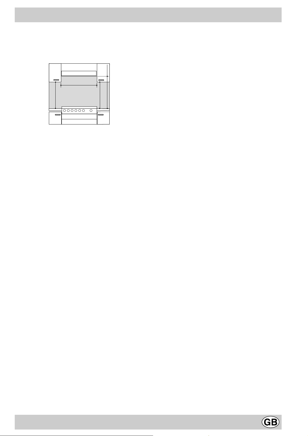
the hob. The minimum distance between the worktop
and kitchen units made of combustible material is 700
mm.
e) The wall in direct contact with the back panel of the
cooker must be made of non-flammable materials.
HOOD
Min. mm.
600
mm.
420
Min.
mm. with hood
420
650
Min. mm.
min.
mm. without hood
700
min.
Connecting the gas
The appliance should be connected to the mains or to a
gas cylinder in compliance with current directives. Bef ore
making the connection, check that the cooker is regulated
for the gas supply you are using. If not, follow the
instructions indicated in the paragraph “Adapting to
different types of gas”. On some models the gas supply
can be connected on the left or on the right, as necessary;
to change the connection, reverse the position of the hose
holder with that of the cap and replace replace the gasket
(supplied with the appliance). When using liquid gas from
a cylinder, install a pressure regulator which complies with
current directive.
Important: check that the supply pressure complies with
the values indicated in table 1 “Characteristics of the
burners and nozzles” since this will ensure saf e operation,
correct consumption and ensure a longer life to your
appliance.
Connection with hose
Make the connection using a gas hose complying with
the the characteristics provided in current directive. The
internal diameter of the pipe used is as follows:
- 8mm for liquid gas;
- 13mm for methane gas.
When installing the hose, remember to take the following
precautions:
• No part of the hose should touch parts whose tempe-
rature exceeds 50°C;
• The length of the hose should be less than 1500 mm;
• The hose should not be subject to twisting or pulling,
and should not have bends or kinks.
• The hose should not touch objects with sharp edges,
any moving parts, and it should not be crushed;
• The full length of the hose should be easy to inspect in
order to check its condition;
Check that the hose fits firmly into place at the two ends
and fix it with clamps complying to current directive.If any
of the above recommendations can not be adopted, fle xible
metal pipes should be used.
Should the cooker be installed according to the conditions
of Class 2, subdivision 1, only a flexible metal pipe which
is in compliance with current safety standards should be
used to make the connection to the gas mains.
Connecting a flexible jointless stainless steel pipe to
a threaded attachment
Remove the hose holder fitted on the appliance. The gas
supply pipe fitting is a threaded 1/2 gas cylindrical male
attachment. Only pipes and gaskets complying with current
directives. The full length of the pipe must not exceed 2000
mm.
Tight control
Important: when installation has been completed, check
the pipe fitting for leaks with a soapy solution. Ne ver use a
flame. Once the connection has been made, ensure that
the flexible metal tube does not touch any moving parts
and is not crushed.
Connecting the supply cable to the mains
Install a normalised plug corresponding to the load
indicated on the data plate. When connecting the cable
directly to the mains, install an omnipolar circuit-breaker
with a minimum contact opening of 3 mm between the
appliance and the mains. The omnipolar circuit breaker
should be sized according to the load and should comply
with current regulations (the earth wire should not be
interrupted by the circuit breaker).
The supply cable should be positioned so that it does not
reach a temperature of more than 50°C with respect to
the room temperature, along its length. Before making the
connection, check that:
• the limiter valve and the home system can support the
appliance load (see data plate);
• the mains is properly earthed in compliance with
current directives and regulations;
• there is easy access to the socket and omnipolar circuit
breaker , once the hob has been installed.
N.B: never use reducers, adaptors or shunts since they
can cause heating or burning.
Adapting the cooker to different types of gas
In order to adapt the cooker to a different type of gas with
respect to the gas for which it was produced (indicated on
the label attached to the lid), follow these steps:
a) replace the hose holder mounted on the appliance with
that supplied in the bag of “cooker accessories”.
Important: the hose holder f or liquid gas is marked 8, the
hose holder for methane gas is marked 13. Alwa ys fit the
sealing gasket.
b) Replacing the burner nozzles on the hob:
• remove the grids and slide the burners from their
housings;
• unscrew the nozzles using a 7 mm socket spanner,
and replace them with nozzles for the new type of gas
(see table 1 “Burner and nozzle characteristics”).
• replace all the components by repeating the steps in
reverse order.
5

c) Minimum regulation of the hob burners:
•
turn the tap to minimum;
• remove the knob and adjust the regulation screw , which
is positioned in or next to the tap pin, until the flame is
small but steady.
N.B.: in the case of liquid gas, the regulation screw
must be screwed in to the bottom.
• check that the flame does not turn off when you turn
the tap quickly from high to low.
d) Regulating the primary air of the burners:
The primary air of the burners requires no regulation.
Adapting the gas oven to different types of gas
a) Replacing the oven burner nozzle:
• remove the warming drawer;
• remove the sliding protection “A” (see Fig.C);
• remove the screw and then the oven burner “V”(see
Fig. D). Remove the oven door to facilitate this
operation.
• unscrew the oven burner nozzle using the special
socket spanner for the nozzles (see Fig. E), or better
still a 7 mm socket spanner , and replace it with a nozzle
suited to the new type of gas (see table 1).
V
Fig.E
b) Minimum regulation of the oven burner without
thermostat:
• light the burner as described in the paragraph “the o ven
knob” of the instruction booklet;
• take the knob to minimum, indicated by C.
• remove the knob and turn the regulation screw which
is positioned in or next to the tap pin until the flame is
small but steady.
N.B.: in the case of liquid gas, the regulation screw
must be screwed in to the bottom;
• check that the burner does not turn off when you turn
the knob from high to low or when you open and close
the oven door quickly.
A
Fig. C Fig. D
Pay particular attention to the plug wires and
thermocouple tubes.
Important
On completion of the operation, replace the old rating
sticker with one indicating the new type of gas used. This
sticker is av ailab le from our Service Centres.
Note
Should the pressure of the gas used be different (or vary)
from the recommended pressure, it is necessary to fit a
suitable pressure regulator onto the inlet pipe in
compliance with current National Regulations relative to
“regulators for channelled gas”.
6
Burner and nozzle characteristics
Table1 (For Hungary)
Burner Diameter
Fast (R) 100 41 0.80 128 3,30 314 128 2,85 262 87 3,00 218
Semi Fast (S) 75 30 0.50 104 2,10 200 104 1,95 179 70 1,90 138
Auxiliary (A) 51 30 0,50 76 1, 15 109 76 1,05 97 52 1,00 73
Oven - 48/49 1,00 107 2,20 209 107 1,95 179 68 2,00 145
Supply pressures
* At 15°C and 1013 mbar-dry gas
P.C.S. G20 37,78 MJ/m
P.C.S. G25.1 39,11 MJ/m
P.C.S. G30 49,47 MJ/kg
S
A
(mm)
3
S
R
1/100 (mm)
Nominal (mbar)
Minimum (mbar)
Maximum (mbar)
3
By-pass
Thermal
power kW
Reduced
Nozzle
1/100
(mm)
G 20 G 25.1 G 30
Thermal
power kW
Nominal
25
20
30
Flow*
l/h
Nozzle
1/100
(mm)
Thermal
power kW
25
20
30
Flow*
l/h
Nozzle
1/100
(mm)
Thermal
power kW
Nominal
30
20
35
Flow*
g/h
K1G2S/HU
Technical Specifications
Inner dimensions of the oven:
Width: 39 cm
Depth: 38 cm
Height: 34 cm
Inner Volume of the Oven:
50 lt
Burners:
adaptable for use with all the types of gas indicated on
the data plate situated inside the flap or, once the
dishwarmer drawer has been opened, on the inside wall
of the left-hand side panel.
94
50
50
7
The European Directive 2002/96/EC on Waste Electrical
and Electronic Equipment (WEEE), requires that old
household electrical appliances must not be disposed of
in the normal unsorted municipal waste stream. Old
appliances must be collected separately in order to optimise
the recovery and recycling of the materials they contain
and reduce the impact on human health and the
environment. The crossed out “wheeled bin” symbol on the
product reminds you of your obligation, that when you dispose of the appliance it must be separately collected.
Consumers should contact their local authority or retailer
for information concerning the correct disposal of their old
appliance.
85/90
7

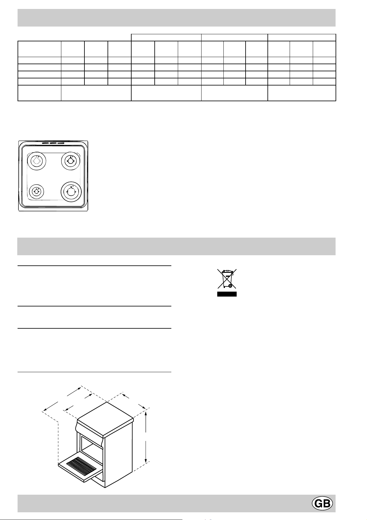
The cooker with gas oven
A. T ray for Catching Overflo ws
B. Gas Burner
D. Top Grate
E. Control P anel
F. Adjustable Feet or Legs
G. Dripping P an or Baking Sheet
J. Flame Failure Device for Cooktop Burners
K. Oven Rack
M. Oven Control Knob
N. Control Knobs for Gas Burners on Hob
J
A
B
E
D
K
G
M
N
The different functions and uses of the oven
The various functions included in the cooker are selected by
operating the control devices located on the cooker control panel.
Control Knobs for the Gas Burners on the Hob (N)
The position of the gas burner controlled by each one of the
knobs is shown by a symbol of a solid ring:•. T o light one of the
burners, hold a lighted match or lighter near the burner. Press
down and turn the corresponding knob in the counter-clockwise
direction to the maximum E setting. Each burner can be operated at its maximum, minimum or intermediate power . Shown
on the knob are the different symbols for off • (the knob is on this
setting when the symbol lines up with the reference mark on the
control panel), for maximum E and minimum C
To obtain these settings, turn the knob counter-clockwise with
respect to the off position. To turn off the burner, turn the knob
clockwise until it stops (corresponding again with the • symbol).
F
production and installation of the appliance.
Attention: Only use the bottom shelf of the oven when using
the rotisserie to cook (where present). For all other types of
cooking, never use the bottom shelf and ne ver place anything
on the bottom of the oven when it is in operation because this
could damage the enamel. Always place your cookware (dishes,
aluminium foil, etc. etc.) on the grate provided with the appliance
inserted especially along the oven guides.
Oven Control Knob (M)
T o light the o ven b urner, apply a lighted match or a lighter
to hole and while pressing in all the way set the oven knob
on maximum E.
Models with Hob Gas Burner Safety Devices to Prevent
Leaks (only on certain models)
These models can be identified by the presence of the device
itself (see detail J).
Important: Since the hob burners are equipped with a safety
device, y ou must hold the control knob in for about 6 seconds
after the burner has been lighted to allow the gas to pass until
the safety thermocouple has heated.
Attention: before using the o ven and grill for the first time , turn
the oven on f or approximately one half hour . Make sure that the
oven is empty, the thermostat on high, the door open, and the
room properly ventilated. The odor which can be detected at
times is due to the ev aporation off the substances used to protect
the oven and the grill during the period between the time of
F
The burner can be used at maximum or intermediate
settings. These settings, maximum E and minimum C
are indicated on the knob, plus off , identified by the symbol
• and operative when this symbol points to the notch.
For the minimum to maximum settings turn the knob
counter clockwise from “Off”.
8
 Loading...