

IMG STAGE LINE PSUB-12 AKA Instruction Manual
BEDIENUNGSANLEITUNG • INSTRUCTION MANUAL
MODE D’EMPLOI • ISTRUZIONI PER L’USO • GEBRUIKSAANWIJZING
MANUAL DE INSTRUCCIONES • INSTRUKCJA OBSŁUGI
SIKKERHEDSOPLYSNINGER • SÄKERHETSFÖRESKRIFTER • TURVALLISUUDESTA
PSUB-12AKA Bestellnummer 25.4310
PSUB-15AKA Bestellnummer 25.4320
SUBWOOFERBOX MIT
STEREO-MISCHVERSTÄRKER
SUBWOOFER SYSTEM WITH STEREO MIXING AMPLIFIER
ENCEINTE SUBWOOFER AVEC AMPLIFICATEUR MIXEUR STÉRÉO
CASSA SUBWOOFER CON AMPLIFICATORE MIXER STEREO

2
Bevor Sie einschalten …
Wir wünschen Ihnen viel Spaß mit Ihrem neuen
Gerät von „img Stage Line“. Bitte lesen Sie diese
Bedienungsanleitung vor dem Betrieb gründlich
durch. Nur so lernen Sie alle Funktionsmöglichkeiten kennen, vermeiden Fehlbedienungen und
schützen sich und Ihr Gerät vor eventuellen Schäden durch unsachgemäßen Gebrauch. Heben
Sie die Anleitung für ein späteres Nachlesen auf.
Der deutsche Text beginnt auf der Seite 4.
Before switching on …
We wish you much pleasure with your new “img
Stage Line” unit. Please read these operating
instructions carefully prior to operating the unit.
Thus, you will get to know all functions of the unit,
operating errors will be prevented, and yourself
and the unit will be protected against any damage
caused by improper use. Please keep the oper ating instructions for later use.
The English text starts on page 8.
Avant toute installation …
Nous vous souhaitons beaucoup de plaisir à utiliser cet appareil “img Stage Line”. Lisez ce mode
dʼemploi entièrement avant toute utilisation. Uniquement ainsi, vous pourrez apprendre lʼensemble des possibilités de fonctionnement de lʼappareil, éviter toute manipulation erronée et vous
protéger, ainsi que lʼappareil, de dommages
éventuels en gendrés par une utilisation inadaptée. Conservez la notice pour pouvoir vous y
reporter ultérieurement.
La version française se trouve page 12.
Prima di accendere …
Vi auguriamo buon divertimento con il vostro
nuovo apparecchio di “img Stage Line”. Leggete
at tentamente le istruzioni prima di mettere in funzione lʼapparecchio. Solo così potete conoscere
tutte le funzionalità, evitare comandi sbagliati e
proteggere voi stessi e lʼapparecchio da eventuali danni in seguito ad un uso improprio. Conservate le istruzioni per poterle consultare anche
in futuro.
Il testo italiano inizia a pagina 16.
D
A
CH
GB
Innan du slår på enheten …
Vi önskar dig mycket glädje med din nya “img
Stage Line” produkt. Läs igenom säkerhetsföre skrif terna innan en heten tas i bruk för att undvika
skador till följd av felaktig hantering. Behåll
instruktionerna för framtida bruk.
Säkerhetsföreskrifterna återfinns på sidan 32.
F
B
CH
I
S
FIN
Antes de la utilización …
Le deseamos una buena utilización para su nue vo aparato “img Stage Line”. Por favor, lea estas
in s trucciones de uso atentamente antes de ha cer
funcionar el aparato. De esta manera conocerá
todas las funciones de la unidad, se pre vendrán
errores de operación, usted y el apa rato estarán
protegidos en contra de todo daño cau sado por
un uso inadecuado. Por favor, guarde las instrucciones para una futura utilización.
El texto en español empieza en la página 24.
Voor u inschakelt …
Wij wensen u veel plezier met uw nieuwe apparaat van “img Stage Line”. Lees deze gebruikershandleiding grondig door, alvorens het apparaat
in gebruik te nemen. Alleen zo leert u alle functies
kennen, vermijdt u foutieve be diening en behoedt
u zichzelf en het apparaat voor eventuele schade
door ondeskundig gebruik. Bewaar de handleiding voor latere raadpleging.
De Nederlandstalige tekst vindt u op pagina 20.
Przed uruchomieniem …
Zyczymy zadowolenia z nowego produktu “img
Stage Line”. Dzięki tej instrukcji obsługi będą
państwo w stanie poznać wszystkie funkcje tego
urządzenia. Stosując się do instrukcji unikną
państwo błędów i ewentualnego uszkodzenia
urządzenia na skutek nieprawidłowego użytkowania. Prosimy zachować instrukcję.
Tekst polski zaczyna się na stronie 28.
Før du tænder …
Tillykke med dit nye “img Stage Line” produkt.
Læs sikkerhedsanvisningerne nøje før ibrugtagning, for at beskytte Dem og enheden mod skader, der skyldes forkert brug. Gem manualen til
senere brug.
Sikkerhedsanvisningerne findes på side 32.
E
PL DK
NL
B
wwwwww..iimmggssttaaggeelliinnee..ccoomm
Ennen kytkemistä …
Toivomme Sinulle paljon miellyttäviä hetkiä uuden
“img Stage Line” laitteen kanssa. Ennen laitteen
käyttöä pyydämme Sinua huolellisesti tutustumaan turvallisuusohjeisiin. Näin vältyt vahingoilta,
joita virheellinen laitteen käyttö saattaa aiheuttaa.
Ole hyvä ja säilytä käyttöohjeet myöhempää tarvetta varten.
Turvallisuusohjeet löytyvät sivulta 33.
3
Signal
signal
signal
segnale
signaal
señal
sygnał
Masse
ground
masse
massa
massa
masa
mase
1 2 3
Masse Signal + Signal
-
ground signal + signal
-
masse signal + signal
-
massa segnale + segnale
-
massa signaal + signaal
-
masa señal + señal
-
mase sygnał + sygnał
-
D
A
CH
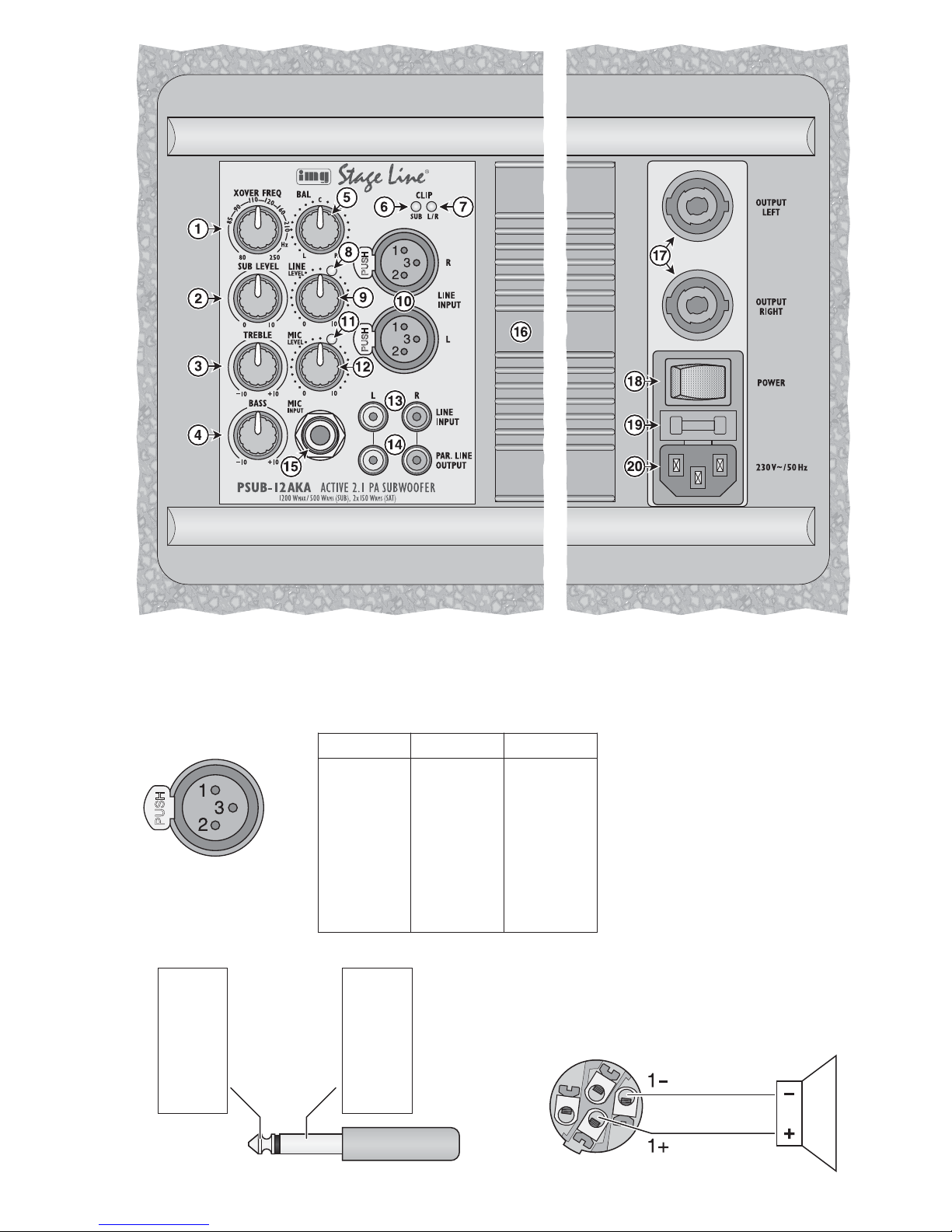
Auf der ausklappbaren Seite 3 finden Sie alle be schriebenen Bedienelemente und Anschlüsse.
1 Übersicht der Bedienelemente
und Anschlüsse
1 Regler XOVER FREQ zum Einstellen der Trenn-
frequenz für den Subwoofer und die Stereo-Lautsprecherausgänge von 80 Hz bis 250 Hz
2 Regler SUB LEVEL für die Subwoofer-Laut-
stärke
3 Klangregler TREBLE für die Höhen
4 Klangregler BASS für die Tiefen
5 Regler BAL zum Einstellen der Balance für die
Stereo-Lautsprecherausgänge (17)
6 LED CLIP SUB; zeigt die Übersteuerung des
Subwoofer-Verstärkers an
7 LED CLIP L/ R; zeigt die Übersteuerung des
Stereo-Verstärkers an
8 Signal-LED
9 Lautstärkeregler LINE LEVEL für den Eingang
LINE INPUT (10) oder (13)
10 Eingang LINE INPUT (XLR-Buchsen) zum sym-
metrischen An schluss einer Stereo-Signalquelle
mit Line-Pegel
11 Signal-LED
12 Lautstärkeregler MIC LEVEL für den Eingang
MIC INPUT (15)
13 Eingang LINE INPUT (Cinch-Buchsen) zum
asymmetrischen An schluss einer Stereo-Signalquelle mit Line-Pegel, alternativ zu den XLRBuchsen (10)
14 Ausgang PAR.LINE OUTPUT (Cinch-Buchsen)
zum Weiterleiten des Line-Eingangssignals
z. B. zu einer weiteren Lautsprecheranlage
15 Eingang MIC INPUT (6,3-mm-Klinkenbuchse,
asymmetrisch beschaltet) zum An schluss eines
Mikrofons
16 Kühlrippen
17 Ausgänge für die Stereolautsprecher; OUTPUT
LEFT für den linken, OUTPUT RIGHT für den
rechten Lautsprecher
18 beleuchteter Netzschalter POWER
19 Halterung für die Netzsicherung
Eine durchgebrannte Sicherung nur durch eine
gleichen Typs ersetzen.
20 Netzbuchse zum Anschluss an eine Steckdose
(230 V~ / 50 Hz) über das beiliegende Netzkabel
2 Hinweise
für den sicheren Gebrauch
Das Gerät entspricht allen relevanten Richtlinien
der EU und ist deshalb mit gekennzeichnet.
Beachten Sie auch unbedingt folgende Punkte:
G
Verwenden Sie das Gerät nur im In nen bereich
und schützen Sie es vor Tropf- und Spritzwasser,
hoher Luftfeuchtigkeit und Hitze (zu lässiger Einsatztemperaturbereich 0 – 40 °C).
G
Stellen Sie keine mit Flüssigkeit gefüllten Ge fäße, z. B. Trinkgläser, auf das Gerät.
G
Die beim Betrieb entstehende Wärme wird durch
Luftzirkulation an den Kühlrippen (16) abgegeben. Decken Sie diese deshalb nicht ab und halten Sie entsprechend Abstand z.B. zu einer
Wand.
G
Nehmen Sie das Gerät nicht in Betrieb oder zie hen Sie sofort den Netzstecker aus der Steckdose,
1. wenn sichtbare Schäden am Gerät oder am
Netzkabel vorhanden sind,
2. wenn nach einem Sturz oder Ähnlichem der
Verdacht auf einen Defekt besteht,
3. wenn Funktionsstörungen auftreten.
Geben Sie das Gerät in jedem Fall zur Reparatur
in eine Fachwerkstatt.
G
Ziehen Sie den Netzstecker nie am Kabel aus
der Steckdose, fassen Sie immer am Stecker an.
G
Verwenden Sie für die Reinigung nur ein trockenes, weiches Tuch, niemals Wasser oder Chemikalien.
G
Wird das Gerät zweckentfremdet, nicht richtig
installiert, falsch be dient oder nicht fach gerecht
repariert, kann keine Haftung für daraus resultierende Sach- oder Personenschäden und keine
Garantie für das Gerät übernommen werden.
WARNUNG Das Gerät wird mit lebensgefährlich
hoher Netzspannung versorgt. Nehmen Sie deshalb niemals selbst Eingriffe am Gerät vor. Es besteht die
Gefahr eines elektrischen Schlages.
Soll das Gerät endgültig aus dem Betrieb
genommen werden, übergeben Sie es zur
umweltgerechten Entsorgung einem örtlichen Recyclingbetrieb.
4

D
A
CH
5
3 Einsatzmöglichkeiten
Die PSUB-12AKA und PSUB-15AKA sind leistungsfähige Aktiv-Subwooferboxen in ro busten
Holzgehäusen. Die Boxen besitzen einen eingebauten Stereo-Endverstärker, zwei mischbare Eingangskanäle und Klangregler. Es sind daher zum
einfachen Aufbau einer kompakten Lautsprecheranlage zusätzlich nur zwei Lautsprecherboxen für
die Mittel-Hochtonwiedergabe erforderlich (z. B.
PAB-306 oder PAB-308 von „img Stage Line“).
Die Subwooferboxen verfügen über eine Frequenzweiche mit einer einstellbaren Trennfrequenz (80 – 250 Hz), die das Signal auf den
Subwoofer und die angeschlossenen Stereolautsprecher aufteilt.
Die Verstärker sind mit einem Limiter gegen
Überlastung und mit Schutzschaltungen gegen
Kurzschluss und Überhitzung ausgestattet.
Die Stativhülse auf der Oberseite des Subwoofers bietet eine Montagemöglichkeit für eine Lautsprecherbox.
4 Aufstellen
Die Subwooferbox auf einen festen Untergrund
stellen. Bei der Verwendung eines einzelnen Subwoofers ist die genaue Positionierung in der Mitte
zwischen den Stereo-Lautsprechern nicht entscheidend, da die von ihm wiedergegebenen sehr
tiefen Frequenzen nicht genau geortet werden können. Stellen Sie ihn jedoch nicht zu dicht an Wände
oder in Ecken, weil dies den Frequenzgang verfälscht und die Wärmeabfuhr des eingebauten Verstärkers behindert.
Auf die Subwooferbox kann eine andere Lautsprecherbox montiert werden. Dazu ein Zwischenstück mit 35 mm Rohrdurchmesser (z. B. aus der
PAST-Serie von „img Stage Line“) in die Stativ hülse auf der Oberseite des Subwoofers stecken
und eine Lautsprecherbox mit einer Stativhülse an
der Unterseite darauf befestigen.
5 Anschließen
Vor dem Anschluss bzw. vor dem Ändern bestehender Anschlüsse die Subwooferbox und die
anzuschließenden Geräte ausschalten.
5.1 Signalquelle anschließen
Eine Signalquelle mit Line-Pegel (z. B. CD-Spie-
ler, Mischpultausgang) an die Cinch-Buchsen LINE
INPUT (13) anschließen. Die Eingänge sind für Stereo-Signale ausgelegt (R = rechter Kanal, L = linker
Kanal). Aus den beiden Stereo-Kanälen der Signalquelle wird intern für den Subwoofer ein MonoSignal gebildet.
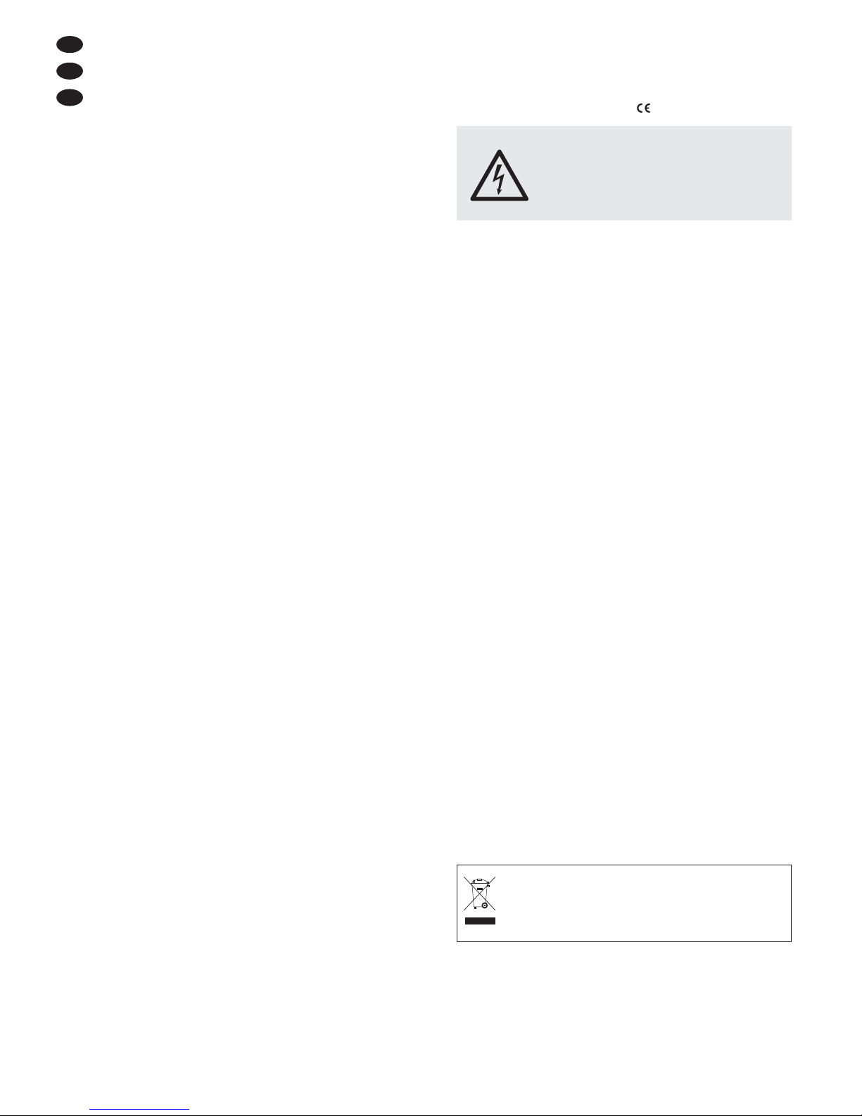
Ist eine Signalquelle mit symmetrischem Ausgangssignal vorhanden (z. B. Mischpultausgang),
diese an die XLR-Eingänge (10) anschließen. Die
Kontaktbelegung der Buchse ist in Abb. 2 dargestellt.
Die Cinch- und XLR-Eingänge können nicht
gleichzeitig verwendet werden!
Ein Mikrofon lässt sich an die Klinken-Buchse
MIC INPUT (15) anschließen. Die Buchse ist für
asymmetrische Signale be schaltet. Die Kontaktbelegung des Steckers ist in Abb. 3 dargestellt. Mikrofone mit symmetrischem Ausgangssignal über
einen Adapter anschließen.
5.2 Signalausgang
An den Cinch-Buchsen PAR. LINE OUTPUT (14)
liegt das Signal der Line-Eingänge (10, 13) an. Hier
kann z. B. eine weitere Lautsprecheranlage oder
ein Aufnahmegerät angeschlossen werden.
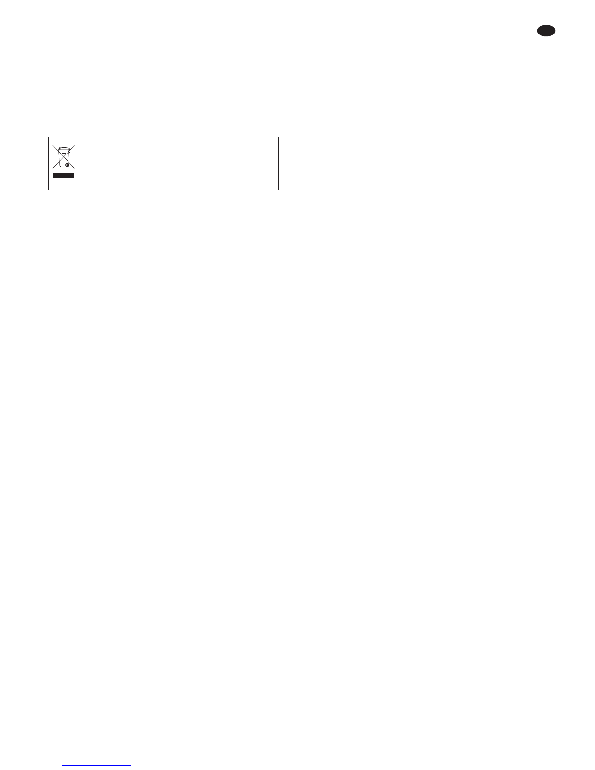
5.3 Stereo-Lautsprecher
Zwei Lautsprecherboxen für die Mittel-HochtonWiedergabe mit einer Impedanz von mindestens
8 Ω, z. B. PAB-306, an die Lautsprecher-Buchsen
(17) OUTPUT LEFT (linker Lautsprecher) und
OUTPUT RIGHT (rechter Lautsprecher) anschließen. Die Kontaktbelegung des Steckers ist in
Abb. 4 dargestellt. Werden mehrere Lautsprecher
an einem Ausgang zusammengeschaltet, darf die
Lautsprecher-Ge samtimpedanz 8 Ω pro Ausgang
nicht unterschreiten.
Einen Lautsprecher-Stecker nach dem Einstecken in die Buchse nach rechts drehen, bis er einrastet. Zum späteren Herausziehen den Sicherungsriegel am Stecker zurückziehen und den
Stecker nach links drehen.
Beim Anschluss der Lautsprecher ist auf die
gleiche Polung beider Lautsprecher zu achten.

6
5.4 Stromversorgung
Das beiliegende Netzkabel an die Netzbuchse (20)
anschließen und den Stecker in eine Steckdose
(230 V~/ 50 Hz) ste cken.
6 Bedienung
Hinweis: Um Schaltgeräusche zu vermeiden, im mer zuerst die ange schlossenen Signalquellen einschalten und dann den Subwoofer. Beim Ausschalten in umgekehrter Reihenfolge vorgehen.
1) Vor dem ersten Einschalten die Regler SUB
LEVEL (2), LINE LEVEL (9) und MIC LEVEL
(12) zunächst auf Minimum (Linksanschlag)
stellen. Zur Grundeinstellung die Klangregler
TREBLE (3) und BASS (4) sowie den BalanceRegler BAL (5) in Mittelposition stellen.
2) Das Gerät mit dem Schalter POWER (18) einschalten. Der Schalter leuchtet.
3) Ist eine Signalquelle an einem Eingang LINE
INPUT (10, 13) angeschlossen, mit dem Regler
LINE LEVEL (9) die gewünschte Lautstärke einstellen. Den Regler nur so weit aufdrehen, dass
der Ton noch nicht verzerrt wiedergegeben wird
und die LED CLIP L/ R (7) nicht leuchtet.
4) Ist ein Mikrofon angeschlossen, dessen Signal
mit dem Regler MIC LEVEL (12) dazumischen
und, wenn erforderlich, den Pegel des Line-Signals mit dem Regler LINE LEVEL (9) reduzieren.
VORSICHT! Um ein Rückkopplungspfeifen zu
vermeiden, halten Sie ein Mikrofon nicht in Richtung des Lautsprechers oder zu nah an ihn
heran. Bei einer zu hoch eingestellten Lautstärke kann ebenfalls eine Rückkopplung auftreten. In diesem Fall oder wenn die LED CLIP L/ R
(7) aufleuchtet, mit dem Regler MIC LEVEL (12)
eine niedrigere Mikrofonlautstärke einstellen.
5) Mit den beiden Reglern TREBLE (3) und BASS
(4) den Klang einstellen. Den gewünschten Tiefbassanteil mit dem Lautstärkeregler des Subwoofers SUB LEVEL (2) dazumischen. Den
Regler nur so weit aufdrehen, dass der Ton nicht
verzerrt wiedergegeben wird. Leuchtet die LED
CLIP SUB (6) auf, ist der Subwooferverstärker
übersteuert. In diesem Fall den Regler entsprechend zurückdrehen oder die Lautstärke des
Eingangssignals reduzieren.
Mit dem Regler XOVER FREQ (1) die Trennfrequenz (80 – 250 Hz) so einstellen, dass der
Subwoofer den Klang der angeschlossenen
Stereo-Lautsprecher optimal ergänzt.
6) Wenn erforderlich, die Lautstärkebalance der
Stereo-Lautsprecher mit dem Regler BAL (5)
korrigieren.
7) Nach dem Gebrauch das Gerät mit dem Schalter POWER wieder ausschalten.
VORSICHT Stellen Sie die Lautstärke nie sehr
hoch ein. Hohe Lautstärken können
auf Dauer das Gehör schädigen! Das
Ohr gewöhnt sich an sie und empfindet sie nach einiger Zeit als nicht
mehr so hoch. Darum eine hohe
Lautstärke nach der Gewöhnung
nicht weiter erhöhen.
CH
A
D

Diese Bedienungsanleitung ist urheberrechtlich für MONACOR®INTERNATIONAL GmbH & Co. KG
ge schützt. Eine Reproduktion für eigene kommerzielle Zwecke – auch auszugsweise – ist untersagt.
Änderungen vorbehalten.
Modell PSUB-12AKA PSUB-15AKA
Verstärkerleistung
Sinusleistung Stereo (an 8 Ω)
Sinusleistung Subwoofer
Spitzengesamtleistung
2 × 150 W
500 W
1200 W
Frequenzbereich (Trennfrequenz variabel)
Subwoofer
Stereo
30 – 80 … 250 Hz
80 … 250 – 20 000 Hz
Rauschabstand > 74 dB
Subwoofer-Lautsprecher
Max. Nennschalldruck
∅ 30 cm (12″)
123 dB
∅ 38 cm (15″)
124 dB
Eingang LINE INPUT (Cinch)
Empfindlichkeit
Max. Eingangsspannung
Impedanz
880 mV
7V
10 kΩ
Eingang LINE INPUT (XLR)
Empfindlichkeit
Max. Eingangsspannung
Impedanz
880 mV
7V
10 kΩ
Eingang MIC INPUT (6,3-mm-Klinke, asym.)
Empfindlichkeit
Max. Eingangsspannung
Impedanz
30 mV
850 mV
1kΩ
Lautsprecher-Ausgänge
Mindestlastimpedanz
Anschluss
8Ω
Lautsprecherbuchsen (speakON
®
-kompatibel)
Einsatztemperatur 0 – 40 °C
Stromversorgung
max. Leistungsaufnahme
230 V~/ 50 Hz
1870 VA
Abmessungen (B × H × T)
Gewicht
460 × 380 × 455 mm
28 kg
600 × 500 × 580 mm
48 kg
7
7 Technische Daten
CH
A
D

8
All operating elements and connections de scribed can be found on the fold-out page 3.
1 Operating Elements
and Connections
1 Control XOVER FREQ to set the crossover fre-
quency for the subwoofer and the stereo
speaker outputs from 80 Hz to 250 Hz
2 Control SUB LEVEL for the subwoofer volume
3 Tone control TREBLE for the high frequencies
4 Tone control BASS for the low frequencies
5 Control BAL to set the balance for the stereo
speaker outputs (17)
6 LED CLIP SUB; to indicate overload of the sub-
woofer amplifier
7 LED CLIP L / R; to indicate overload of the stereo
amplifier
8 Signal LED
9 Volume control LINE LEVEL for the LINE INPUT
(10) or (13)
10 LINE INPUT (XLR jacks) for balanced connec-
tion of a stereo signal source with line level
11 Signal LED
12 Volume control MIC LEVEL for the MIC INPUT
(15)
13 LINE INPUT (RCA jacks) for unbalanced con-
nection of a stereo signal source with line level,
as an alternative to the XLR jacks (10)
14 PAR.LINE OUTPUT (RCA jacks) to route the
line input signal, e. g. to another sound system
15 MIC INPUT (6.3 mm jack, unbalanced) to con-
nect a microphone
16 Cooling fins
17 Outputs for the stereo speakers; OUTPUT
LEFT for the left speaker, OUTPUT RIGHT for
the right speaker
18 Illuminated POWER switch
19 Support for the mains fuse
Only replace a blown fuse by one of the same
type.
20 Mains jack for connection to a socket (230 V~/
50 Hz) via the mains cable provided
2 Safety Notes
This unit corresponds to all relevant directives of
the EU and is therefore marked with .
Please observe the following items in any case:
G
The unit is suitable for indoor use only. Protect it
against dripping water and splash water, high air
humidity and heat (admissible ambient temperature range 0 – 40 °C).
G
Do not place any vessel filled with liquid on the
unit, e. g. a drinking glass.
G
The heat generated inside the unit during operation is dissipated by air circulation at the cooling
fins (16). Never cover the cooling fins and keep a
sufficient distance, e. g. to walls.
G
Do not operate the unit or immediately disconnect the mains plug from the socket
1. if the unit or the mains cable is visibly damaged,
2. if a defect might have occurred after the unit
was dropped or suffered a similar accident,
3. if malfunctions occur.
In any case the unit must be repaired by skilled
personnel.
G
Never pull the mains cable to disconnect the
mains plug from the socket, always seize the plug.
G
For cleaning only use a dry, soft cloth; never use
water or chemicals.
G
No guarantee claims for the unit and no liability
for any resulting personal damage or material
damage will be accepted if the unit is used for
other purposes than originally intended, if it is not
correctly installed or operated, or if it is not
repaired in an expert way.
G
Important for U. K. Customers!
The wires in this mains lead are coloured in
accordance with the following code:
green/yellow = earth
blue = neutral
brown = live
As the colours of the wires in the mains lead of
this appliance may not correspond with the
coloured markings identifying the terminals in
your plug, proceed as follows:
1. The wire which is coloured green and yellow
must be connected to the terminal in the plug
which is marked with the letter E or by the earth
symbol , or coloured green or green and yellow.
WARNING
The unit uses dangerous mains voltage. Leave servicing to skilled personnel only; inexpert handling may
result in electric shock.
GB
9
2. The wire which is coloured blue must be connected to the terminal which is marked with the
letter N or coloured black.
3. The wire which is coloured brown must be connected to the terminal which is marked with the
letter L or coloured red.
Warning – This appliance must be earthed.
3 Applications
The PSUB-12AKA and PSUB-15AKA are powerful
active subwoofer systems in rugged wooden cabinets. They are equipped with an integrated stereo
power amplifier, two mixable input channels and
tone controls. This makes it easy to set up a compact sound system: Only two speaker systems
for mid-high range reproduction are additionally
required (e. g. PAB-306 or PAB-308 from “img
Stage Line”).
The subwoofer systems feature a crossover
network with adjustable crossover frequency
(80 – 250 Hz) to distribute the signal to the subwoofer and the stereo speakers connected.
The amplifiers are protected with a limiter
against overload and with protective circuits
against short circuit and overheating.
The stand sleeve on the upper side of the subwoofer offers a mounting facility for a speaker system.
4 Setting Up
Set up the subwoofer on solid ground. When using
a single subwoofer, it is not essential to place it
exactly in the middle between the stereo speakers
as you will not be able to precisely locate the very
low frequencies reproduced by the subwoofer.
However, do not place it too close to walls or in corners; this would distort the frequency response and
prevent heat dissipation of the integrated amplifier.
It is possible to install another speaker system
on top of the subwoofer system: Insert an adapter
with a tube diameter of 35 mm (e. g. from the PAST
series of “img Stage Line”) into the stand sleeve on
the upper side of the subwoofer, then fasten a
speaker system equipped with a stand sleeve on its
lower side on top of the subwoofer system.
5 Connecting
Prior to making connections or changing any existing connections, switch off the subwoofer system
and the units to be connected.
5.1 Connecting a signal source
Connect a signal source with line level (e. g. CD
player, output of a mixer) to the RCA jacks LINE
INPUT (13). The inputs are designed for stereo signals (R = right channel, L = left channel). The two
stereo channels of the signal source are internally
combined to a mono signal for the subwoofer.
If a signal source with balanced output signal is
available (e. g. output of a mixer), connect this
source to the XLR inputs (10). The configuration of
the jack is shown in figure. 2.
The RCA inputs and the XLR inputs cannot be
used at the same time!
To connect a microphone use the 6.3 mm jack
MIC INPUT (15). The jack is unbalanced. The configuration of the plug is shown in figure 3. To connect microphones with balanced output signal, use
an adapter.
5.2 Signal output
The signal of the line inputs (10, 13) is available at
the RCA jacks PAR. LINE OUTPUT (14). They can
be used e. g. to connect another sound system or a
recorder.
5.3 Stereo speakers
Connect two speaker systems for mid-high range
reproduction with a minimum impedance of 8 Ω,
e. g. PAB-306, to the speaker jacks (17) OUTPUT
LEFT (left speaker) and OUTPUT RIGHT (right
speaker). The configuration of the plug is shown in
figure 4. When several speakers are interconnected at an output, the total impedance of the
speakers must not fall below 8 Ω at any output.
After connecting a speaker plug to the jack, turn
the plug clockwise until it engages. To disconnect
the plug, pull back the locking tab of the plug and
turn the plug counter-clockwise.
When connecting the speakers, make sure that
both speakers have the same polarity.
5.4 Power supply
Connect the mains cable provided to the mains
jack (20) and the plug to a mains socket (230 V~/
50 Hz).
If the unit is to be put out of operation
definitively, take it to a local recycling plant
for a disposal which is not harmful to the
environment.
GB

6 Operation
Note: To prevent switching noise, always switch on
the signal sources connected before switching on
the subwoofer. When switching off, proceed in the
reverse order.
1) Prior to initial operation, set the controls SUB
LEVEL (2), LINE LEVEL (9) and MIC LEVEL
(12) to minimum (left stop) for the time being.
For basic setting, set the tone controls TREBLE
(3) and BASS (4) and the balance control BAL
(5) to mid-position.
2) Switch on the unit with the POWER switch (18).
The switch is illuminated.
3) If a signal source is connected to the LINE
INPUT (10, 13), adjust the desired volume with
the control LINE LEVEL (9). Only turn up the
control to such an extent that the sound reproduced is not yet distorted and the LED CLIP L /R
(7) does not yet light up.
4) If a microphone is connected, add its signal to
the mix with the control MIC LEVEL (12). If
required, reduce the level of the line signal with
the control LINE LEVEL (9).
CAUTION! To prevent feedback noise, do not
point the microphone towards the speaker and
do not hold it too close to it. Feedback noise may
also occur when the volume is too high. In this
case, or if the LED CLIP L / R (7) lights up,
reduce the microphone volume with the control
MIC LEVEL (12).
5) Adjust the sound with the two controls TREBLE
(3) and BASS (4). Add the desired low bass part
to the mix with the volume control of the subwoofer SUB LEVEL (2). Only turn up the control
to such an extent that the sound is not yet distorted. If the LED CLIP SUB (6) lights up, it is an
indication for overload of the subwoofer amplifier. In this case, turn back the control accordingly or reduce the volume of the input signal.
Use the control XOVER FREQ (1) to set the
crossover frequency (80 – 250 Hz) in such a way
that the subwoofer ideally complements the
sound of the stereo speakers connected.
6) If required, readjust the volume balance of the
stereo speakers with the control BAL (5).
7) After use, switch off the subwoofer system with
the POWER switch.
CAUTION Never adjust a very high volume. Per-
manent high volumes may damage
your hearing! Your ear will get accustomed to high volumes which do not
seem to be that high after some time.
Therefore, do not further increase a
high volume after getting used to it.
10
GB

11
GB
All rights reserved by MONACOR®INTERNATIONAL GmbH & Co. KG. No part of this instruction manual
may be reproduced in any form or by any means for any commercial use.
Subject to technical modification.
Model PSUB-12AKA PSUB-15AKA
Amplifier power
RMS power, stereo (at 8Ω)
RMS power, subwoofer
Total peak power
2 × 150 W
500 W
1200 W
Frequency range (with variable crossover frequency)
Subwoofer
Stereo
30 – 80 … 250 Hz
80 … 250 – 20 000 Hz
S / N ratio > 74 dB
Subwoofer speaker
Max. nominal SPL
∅ 30 cm (12″)
123 dB
∅ 38 cm (15″)
124 dB
LINE INPUT (RCA)
Sensitivity
Max. input voltage
Impedance
880 mV
7V
10 kΩ
LINE INPUT (XLR)
Sensitivity
Max. input voltage
Impedance
880 mV
7V
10 kΩ
MIC INPUT (6.3 mm jack, unbal.)
Sensitivity
Max. input voltage
Impedance
30 mV
850 mV
1kΩ
Speaker outputs
Min. load impedance
Connection
8Ω
speaker jacks (speakON
®
compatible)
Ambient temperature 0 – 40 °C
Power supply
Max. power consumption
230 V~/ 50 Hz
1870 VA
Dimensions (W × H × D)
Weight
460 × 380 × 455 mm
28 kg
600 × 500 × 580 mm
48 kg
7 Specifications
 Loading...