

Page 1
QUESTIONS?
As a manufacturer, we are committed to providing complete
customer satisfaction. If you
have questions, or find that there
are missing or damaged parts,
we will guarantee you complete
satisfaction through direct assistance from our factory.
TO AVOID UNNECESSARY
DELAYS, PLEASE CALL DIRECT
TO OUR TOLL-FREE CUSTOMER
HOT LINE. The trained technicians on our customer hot line
will provide immediate assistance, free of charge to you.
CUSTOMER HOT LINE:
1-800-999-3756
Mon.ÐFri., 6 a.m.Ð6 p.m. MST
Model No. IMBE40890
Serial No.
Write the serial number in the
space above for reference.
CAUTION
Read all precautions and instructions in this manual before using
this equipment. Save this manual
for future reference.
Serial Number
Decal (under seat)
USERÕS MANUAL
Patent Pending
¨
Visit our website at
www.imagefitness.com
new products, prizes,
fitness tips, and much more!
Page 2
2
Warning Decal Placement . . . . . . . . . . . . . . . . . . . . . . . . . . . . . . . . . . . . . . . . . . . . . . . . . . . . . . . . . . . . . . . . 2
Important Precautions . . . . . . . . . . . . . . . . . . . . . . . . . . . . . . . . . . . . . . . . . . . . . . . . . . . . . . . . . . . . . . . . . . . 3
Before You Begin . . . . . . . . . . . . . . . . . . . . . . . . . . . . . . . . . . . . . . . . . . . . . . . . . . . . . . . . . . . . . . . . . . . . . . 4
Part Identification Chart . . . . . . . . . . . . . . . . . . . . . . . . . . . . . . . . . . . . . . . . . . . . . . . . . . . . . . . . . . . . . . . . . . 5
Assembly . . . . . . . . . . . . . . . . . . . . . . . . . . . . . . . . . . . . . . . . . . . . . . . . . . . . . . . . . . . . . . . . . . . . . . . . . . . . 6
Adjusting the Weight Bench . . . . . . . . . . . . . . . . . . . . . . . . . . . . . . . . . . . . . . . . . . . . . . . . . . . . . . . . . . . . . . 13
Ordering Replacement Parts . . . . . . . . . . . . . . . . . . . . . . . . . . . . . . . . . . . . . . . . . . . . . . . . . . . . . .Back Cover
Limited Warranty . . . . . . . . . . . . . . . . . . . . . . . . . . . . . . . . . . . . . . . . . . . . . . . . . . . . . . . . . . . . . . . Back Cover
Note: A Part List/Exploded Drawing is attached in the center of this manual. Remove the Part List/Exploded
Drawing before beginning assembly.
Table of Contents
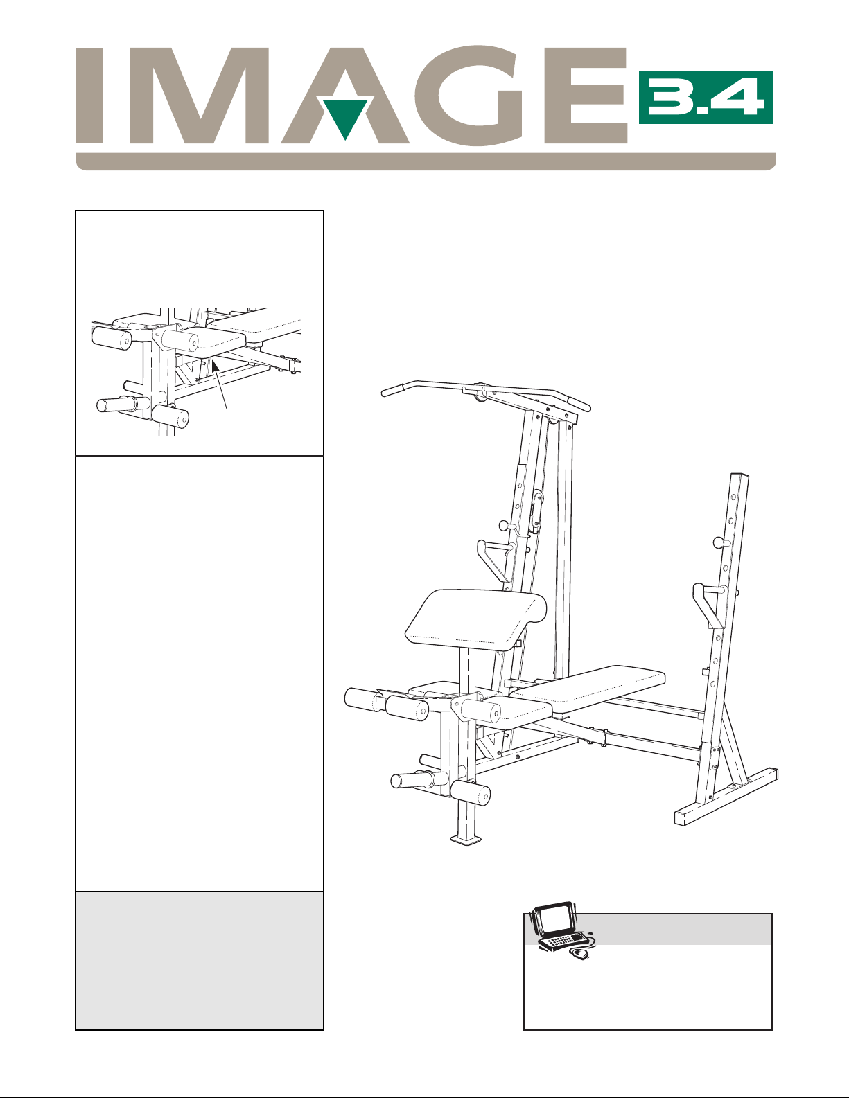
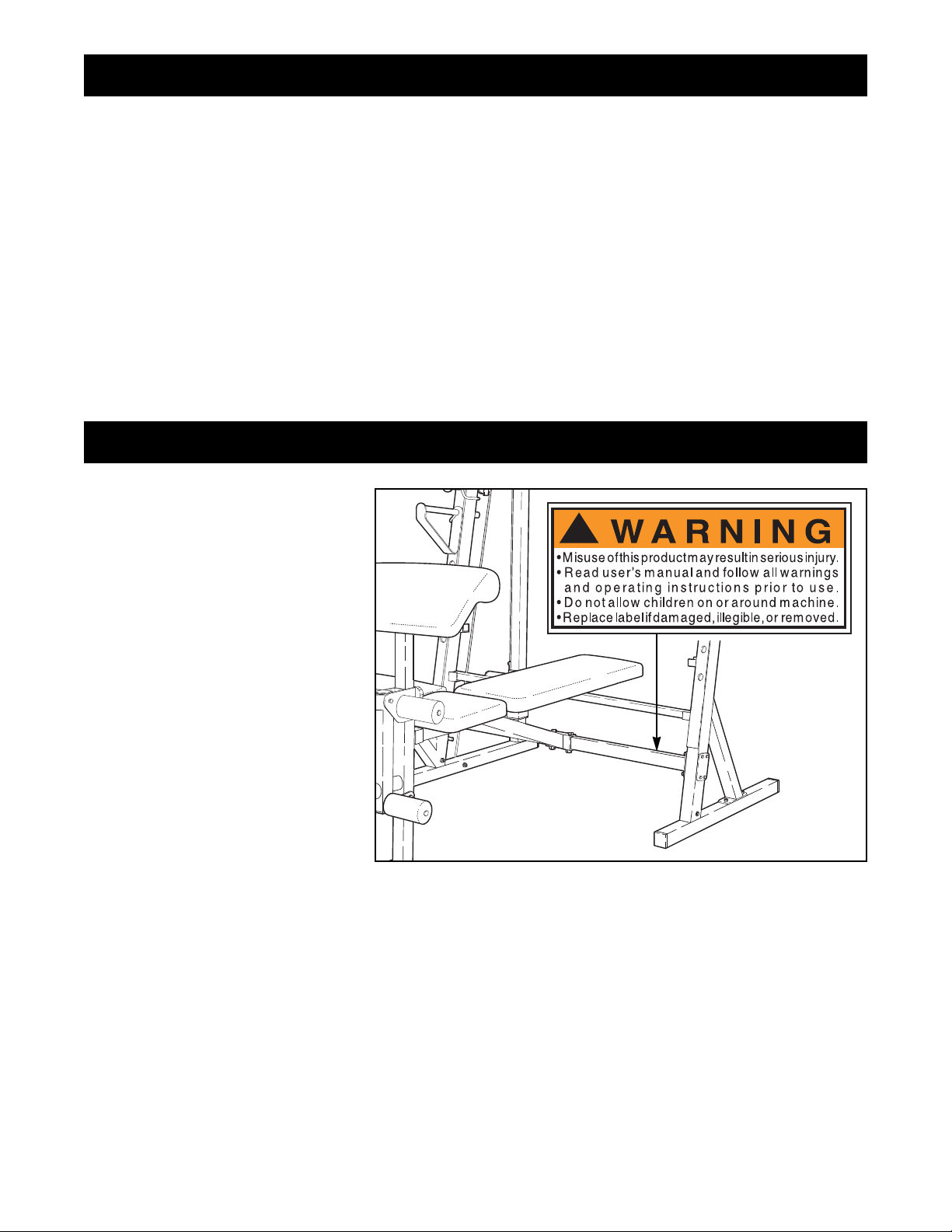
The decal shown at the right has
been placed on the weight
bench. If the decal is missing, or
if it is not legible, please call our
Customer Service Department
toll-free at 1-800-999-3756,
Monday through Friday, 6 a.m.
until 6 p.m. Mountain Time, to
order a replacement decal. Apply
the replacement decal in the
location shown.
Warning Decal Placement
!
Page 3

3
WARNING: Before beginning this or any exercise program, consult your physician. This is especially
important for persons over the age of 35 or persons with pre-existing health problems. Read all
instructions before using. ICON assumes no responsibility for personal injury or property damage
sustained by or through the use of this product.
WARNING: To reduce the risk of serious injury, read the following important precautions
before using the weight bench.
Important Precautions
1. Read all instructions in this manual before
using the weight bench. Use the weight
bench only as described in this manual.
2. It is the responsibility of the owner to ensure
that all users of the weight bench are adequately informed of all precautions.
3. The weight bench is intended for home use
only. Do not use the weight bench in any
commercial, rental or institutional setting.
4. Use the weight bench only on a level surface.
Cover the floor beneath the weight bench for
protection.
5. Inspect and tighten all parts each time you
use the weight bench. Replace any worn
parts immediately.
6. Keep children under 12 and pets away from
the weight bench at all times.
7. Keep hands and feet away from moving
parts.
8. Always wear athletic shoes for foot protection while exercising.
9. Always make sure there is an equal amount
of weight (not included) on each side of your
barbell (not included).
10. If you feel pain or dizziness at any time while
exercising, stop immediately and begin cooling down.
11. The weight bench is designed to support a
maximum of 560 pounds, including the user,
a barbell and weights. Do not place more
than 310 pounds, including the barbell, on
the weight rests. Do not place more than 150
pounds on the weight carriage. Do not place
more than 150 pounds on the leg lever for
normal use.
12. Make sure that the cable remains on the pulleys at all times. If the cable binds as you are
exercising, stop immediately and make sure
that the cable is on the pulleys.
13. Check the cables periodically to make sure
that they are tight. See assembly step 12 on
page 10 for cable tightening instructions.
14. Always set both weight rests and both safety
spotters at the same height.
15. Always exercise with a partner. When you
are performing bench press exercises or toe
raise exercises, your partner should stand
behind you to catch the barbell if you cannot
complete a repetition.
16. Always disconnect the lat bar from the
weight bench when performing an exercise
that does not use the lat bar.
17. Always secure weights with the included
weight clips when they are mounted on a
barbell, the leg lever, or the weight carriage.
Page 4
4
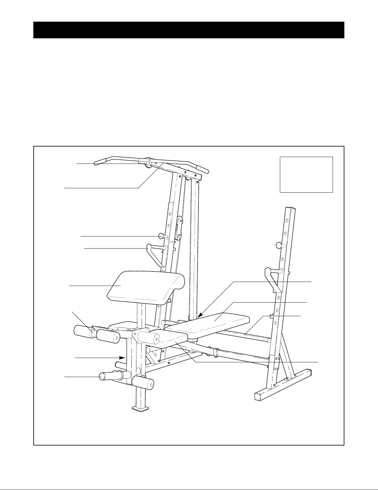
Weight
Carriage
Weight
Tube
High Pulley
Station
Low Pulley
Station
Lat Bar
Weight Rest
Safety Spotter
Curl Pad
Right Side
Left Side
Note: The terms Òright sideÓ and Òleft sideÓ are determined relative to a person sitting on the bench;
they do not correspond to right and left on the drawings in this manual.
Backrest
Adjustment
Tube
Leg Lever
Seat
Thank you for selecting the versatile IMAGE¨3.4
Weight Bench. The IMAGE¨3.4 is designed to help
you develop every major muscle group of the body.
Whether your goal is a shapely figure, dramatic muscle size and strength, or a healthier cardiovascular
system, the 3.4 Weight Bench will help you achieve
the specific results you want.
For your benefit, read this manual carefully before
using the IMAGE¨3.4 Weight Bench. If you have
additional questions, please call our Customer Service
Department toll-free at 1-800-999-3756, Monday
through Friday, 6 a.m. until 6 p.m. Mountain Time
(excluding holidays). To help us assist you, please
note the product model number and serial number
before calling. The model number is IMBE40890. The
serial number can be found on a decal attached to the
IMAGE¨3.4 Weight Bench (see the front cover of this
manual).
Before reading further, please review the drawing
below and familiarize yourself with the parts that are
labeled.
Before You Begin
Assembled
Dimensions:
Height: 72Ó
Base: 56Ó x 84Ó
Page 5
5
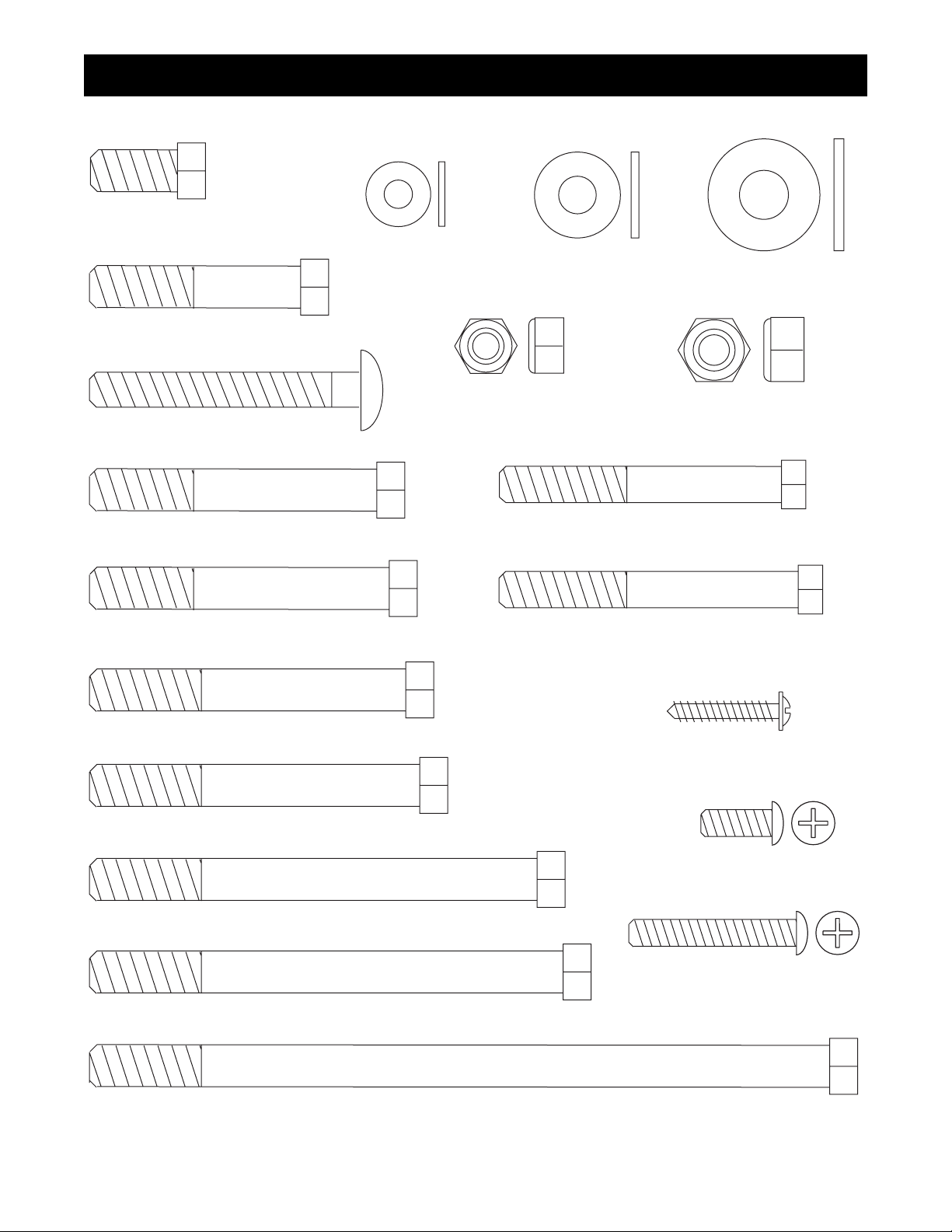
Part Identification ChartÑModel No. IMBE40890
R0999A
M10 Nylon Locknut (11)Ð29
M8 Nylon Locknut (13)Ð2
M6 Washer (30)Ð4
M6 x 16mm Screw (3)Ð6
M8 x 64mm Bolt (43)Ð1
M6 x 38mm Screw (4)Ð4
Protector Strip Screw (49)Ð14
M8 x 68mm Bolt (60)Ð1
M8 Washer (23)Ð2
M10 x 19mm Bolt (57)Ð1
M10 x 75mm Bolt (8)Ð1
M10 x 62mm Carriage Bolt (59)Ð2
M10 x 65mm Bolt (67)Ð5
M10 x 168mm Bolt (22)Ð1
M10 x 48mm Bolt (55)Ð2
M10 x108mm Bolt (34)Ð3
M10 x 68mm Bolt (33)Ð5
M10 x 72mm Bolt (68)Ð8
M10 x102mm Bolt (71)Ð1
M10 Washer (6)Ð15
Page 6

6
1. Before beginning assembly, make sure that you
understand the information in the box above.
Note: Some of the parts described in the assembly steps may be pre-assembled.
Press a 2Ó Square Inner Cap (17) into the indicated
end of the Right Stabilizer (26). Press a 2Ó Square
Outer Cap (58) onto the other end of the Stabilizer.
Press a 48mm Round Inner Cap (12) into each end of
the welded tube on the Right Stabilizer (26).
Press a 1.5Ó Square Inner Cap (72) into the storage
tube on the Right Upright (2).
Slide the Right Upright (2) onto the Right Stabilizer
(26) as shown. Attach the Upright to the Stabilizer
with an M10 x 65mm Bolt (67), two M10 Washers (6)
and an M10 Nylon Locknut (11). Do not tighten the
Nylon Locknut yet.
Set the upright assembly aside and make sure it
cannot fall over.
1
Before beginning assembly, carefully read the
following information and instructions:
¥ Assembly requires two people.
¥ Place all parts in a cleared area and remove the
packing materials. Do not dispose of the packing
materials until assembly is completed.
¥ Tighten all parts as you assemble them, unless
instructed to do otherwise.
¥ For help identifying the small parts, use the PART
IDENTIFICATION CHART on page 5.
¥ As you assemble the weight bench, make sure all
parts are oriented as shown in the drawings.
The following tools (not included) are required
for assembly:
¥ Two (2) adjustable wrenches
¥ One (1) rubber mallet
¥ One (1) standard screwdriver
¥ One (1) phillips screwdriver
¥ Lubricant, such as grease or petroleum jelly
plus soapy water.
Assembly will be more convenient if you have the
following tools: A socket set, a set of open-end or
closed-end wrenches or a set of ratchet wrenches.
Assembly
Make Things Easier for Yourself!
Everything in this manual is designed to ensure
that our products can be assembled successfully
by anyone. However, it is important to recognize
that this is a sophisticated product with many
small parts and, consequently, assembly will
take time. Most people find that by setting aside
plenty of time, and by deciding to make the task
enjoyable, assembly will go smoothly.
17
12
12
2
26
6
6
67
11
72
58
Page 7

3. Align the holes in a 4-hole Support Plate (16) with the
holes in the Right Upright (2). Insert four M10 x
72mm Bolts (68) into the Support Plate and the Right
Upright. Make sure that the Bolts are inserted from
the direction shown.
Align the holes in another 4-hole Support Plate (16)
with the holes in the Left Upright (1). Insert four M10
x 72mm Bolts (68) into the Support Plate and the Left
Upright. Make sure that the Bolts are inserted from
the direction shown.
While a second person holds the Right Upright (2),
slide the bracket on the Crossbar (20) over the four
M10 x 72mm Bolts (68) in the Right Upright. Make
sure that the Crossbar is turned so the warning
decal is on top. Attach the Crossbar with four M10
Nylon Locknuts (11). Do not tighten the Nylon
Locknuts yet.
Attach the Crossbar (20) to the Left Upright (1) as
described above.
3
7
2. Press a 2Ó Square Outer Cap (58) onto each end of
the Left Stabilizer (25).
Press a 51mm x 76mm Inner Cap (24) into the top of
the Left Upright (1).
Insert two M10 x 62mm Carriage Bolts (59) into the
holes in the Left Stabilizer (25) from below.
Slide the Left Upright (1) onto the Left Stabilizer (25)
as shown, so the bracket on the Left Upright fits over
the M10 x 62mm Carriage Bolts (59) in the Left
Stabilizer.
Attach the Left Upright (1) to the Left Stabilizer (25)
with an M10 x 65mm Bolt (67), two M10 Washers (6),
and an M10 Nylon Locknut (11). Thread an M10
Nylon Locknut onto each of the M10 x 62mm
Carriage Bolts (59) in the Stabilizer. Do not tighten
the Nylon Locknuts yet.
2
1
24
59
25
67
11
6
6
11
58
58
1
68
68
68
68
16
16
2
20
Decal
11
11
11
11
Page 8

8
4. Snap a Carriage Bushing (56) into the Weight Stop
(53). Slide both parts onto the Rear Upright (9), making sure that the Carriage Bushing (56) is on top.
Attach the parts to the indicated hole in the Rear
Upright with an M8 x 68mm Bolt (60) and an M8
Nylon Locknut (13).
Next, slide the Rear Upright (9) onto the Right
Stabilizer (26). Make sure that the Rear Upright is
turned so the upper end slants in the direction
shown. Attach the Rear Upright with an M10 x 65mm
Bolt (67), two M10 Washers (6), and an M10 Nylon
Locknut (11). Do not tighten the Nylon Locknut yet.
4
6. Press a 2Ó Square Inner Cap (17) into the open end
of the Top Frame (7).
Place the Top Frame (7) onto the Right Upright (2)
and the Rear Upright (9).
Attach the Top Frame (7) to the Right Upright (2) with
an M10 x 65mm Bolt (67), two M10 Washers (6) and
an M10 Nylon Locknut (11). Attach the Top Frame to
the Rear Upright (9) in the same manner.
6
67
60
6
56
53
6
hole
13
11
26
67
6
67
2
9
11
11
6
7
17
6
5. Press Carriage Bushings (56) into the top and bottom
of the Weight Carriage (47).
Press a 48mm Round Inner Cap (12) into each end of
the weight tube on the Weight Carriage (47).
Identify the Upper Cable (45); this is the longest of
the two Cables. Note that the Cable has a ball/loop
on one end and a loop on the other end. Attach the
end with the loop to the indicated bracket on the
Weight Carriage (47) with an M10 x 19mm Bolt (57)
and an M10 Nylon Locknut (11). Make sure the Bolt
is inserted from the direction shown.
Slide the Weight Carriage (47) onto the Rear Upright
(9).
5
56
45
12
57
47
12
9
56
11
9
9
Low
Side
High
Side
Page 9

9
7. The Upper Cable (45) was attached to the Weight
Carriage in step 5. Wrap the Upper Cable around a
Pulley (35) in the direction shown.
Attach the Pulley (35) and a Cable Trap (61) to the
indicated hole in the Top Frame (7) with an M10 x
108mm Bolt (34), a 15.8mm Spacer (31), an M10
Washer (6) and an M10 Nylon Locknut (11). Make
sure the Cable Trap is oriented as shown, so it
will hold the Cable in place.
11
6
31
35
61
34
7
45
7
8. Note: If the Pulley Plates (62) are pre-assembled,
remove both Pulleys (35) from the Pulley Plates.
Wrap the Upper Cable (45) around a Pulley (35) in
the direction shown. Attach the Pulley and a Cable
Trap (61) to the upper holes in the two Pulley Plates
(62). Note: Make sure that both Pulley Plates are
oriented as shown, so the ends with several holes
are pointed towards the floor. Attach the Pulley with
an M10 x 48mm Bolt (55) and an M10 Nylon Locknut
(11). Make sure the Cable Trap is oriented as
shown.
61
62
35
45
55
Holes
11
8
9. Wrap the Upper Cable (45) around a Pulley (35) in
the direction shown. Attach the Pulley and a Cable
Trap (61) to the indicated hole in the Top Frame (7)
with an M10 x 108mm Bolt (34), a 15.8mm Spacer
(31), an M10 Washer (6) and an M10 Nylon Locknut
(11). Make sure the Cable Trap is oriented as
shown.
11
6
31
61
34
7
35
45
9
10. Route the Upper Cable (45) over a Pulley (35) in the
direction shown. Attach the Pulley to the indicated
hole in the Top Frame (7) with an M10 x 108mm Bolt
(34), a 15.8mm Spacer (31), an M10 Washer (6) and
an M10 Nylon Locknut (11). Make sure the Cable is
between the Pulley and the welded pin (not visible) on the Top Frame.
45
7
35
34
31
6
11
10
Welded
Pin
Page 10

10
11. Locate the Lower Cable (39) and note that it has a
ball/loop on one end and a loop only on the other.
See drawing 11a. Route the end of the Lower Cable
with the loop through the cable guide on the outside
of the Right Upright (2).
See drawing 11. Route the Lower Cable (39) around
a Pulley (35) in the direction shown. Attach the Pulley
and one end of the 2-hole Oval Support Plate (74) to
the welded tube on the Right Upright (2) with an M10
x 102mm Bolt (71) and an M10 Nylon Locknut (11).
Do not tighten the Nylon Locknut yet. Make sure
that the Support Plate is angled as shown and that it
is attached on the inside of the Upright (2).
Important: The Cable must be positioned between
the Pulley and the welded pin as shown in drawing 11a.
12. Wrap the Lower Cable (39) around a Pulley (35) in
the direction shown. Attach the Pulley and a Cable
Trap (61) to the lower set of holes in the two Pulley
Plates (62) with an M10 x 48mm Bolt (55) and an
M10 Nylon Locknut (11). Make sure that the Cable
Trap is between the Pulley Brackets and that it is
oriented as shown.
Slide the loop on the Lower Cable (39) onto an M10 x
68mm Bolt (33). Insert the Bolt into the indicated hole
(see drawing 11a) in the Right Stabilizer (26) and
through the 2-hole Oval Support Plate (74). Secure
the Cable and Plate with an M10 Nylon Locknut (11).
IMPORTANT: The type of cable used on the
weight bench may stretch over time. If this
occurs, you can tighten the cables by moving the
lower Pulley (35) attached to the Pulley Plate (62).
To do this, remove the M10 x 48mm Bolt (55) and
the M10 Nylon Locknut (11). Move the Bolt to one
of the higher adjustment holes in the Pulley
Plates. As you re-attach the Pulley and the Cable
Trap (61), make sure the Cable Trap is oriented as
shown.
Go back and tighten all of the M10 Nylon
Locknuts (11) used in steps 1 through 12.
2
2
11
74
61
11
39
26
55
62
11
74
33
35
1
35
71
39
11
11a
35
39
Cable Guide
Welded Tube
Adjustment
Holes
Hole for End of Cable
12
Welded Pin
Page 11

11
13. Insert two M10 x 68mm Bolts (33) into the 2-hole
Support Plate (70), the Front Leg (19), and the bracket on the Bench Frame (5) as shown. Tighten an M10
Nylon Locknut (11) onto each Bolt.
13
33
11
11
5
70
19
14. Align the bracket on the Bench Frame (5) with the
holes in the center of the Crossbar (20). Attach the
Bench Frame (5) to the Crossbar with two M10 x
68mm Bolts (33) and two M10 Nylon Locknuts (11).
14
11
5
20
33
15. Attach the Leg Lever Lock (41) to the indicated hole
in the Front Leg (19) with an M8 x 64mm Bolt (43),
two M8 Washers (23), and an M8 Nylon Locknut (13).
Do not overtighten the Nylon Locknut; the Leg
Lever Lock must pivot easily.
Attach the Bumper (48) to the indicated hole in the
Front Leg (19) with a Bumper Screw (64).
15
64
48
23
19
43
41
13
23
16. Press a 2Ó Square Inner Cap (17) into each end of
the Leg Lever (18). Press a 48mm Round Inner Cap
(12) into the end of the weight tube on the Leg Lever.
Lubricate an M10 x 75mm Bolt (8). Attach the Leg
Lever (18) to the bracket on the Front Leg (19) with
the Bolt and an M10 Nylon Locknut (11). Do not
overtighten the Nylon Locknut; it must be easy to
pivot the Leg Lever.
16
17
12
19
17
Lubricate
18
8
17
11
Page 12

12
17. Press a 3/4Ó Round Inner Cap (54) into each end of
the three Pad Tubes (38).
Press a Foam Pad (10) onto one end of a Pad Tube
(38). Insert the Pad Tube into one set of holes in the
bracket on the Front Leg (19). Press a Foam Pad
onto the other end of the Pad Tube.
Mount the other two Pad Tubes (38) in the indicated
holes in the Leg Lever (18) as described above.
17
18
38
54
38
54
54
10
54
10
10
10
19
18. Press a 30mm Square Inner Cap (32) into each end
of the Adjustment Tube (29).
Press a 1Ó Square Inner Cap (28) into each end of
the two Backrest Tubes (27). Attach the Backrest
Tubes to the Backrest (15) with four M6 x 38mm
Screws (4) and four M6 Washers (30). Note: Make
sure the indicated holes in the Backrest Tubes are
oriented as shown (on the wide end of the
Backrest).
18
28
30
15
28
29
4
30
32
30
4
32
27
19. Lubricate the M10 x 168mm Bolt (22). Attach the
Backrest (15) to the welded tube on the Bench Frame
(5) with the Bolt, two M10 Washers (6) and an M10
Nylon Locknut (11). Note: Do not overtighten the
Nylon Locknut; it must be easy to pivot the
Backrest.
19
6
6
Welded
Tube
11
15
5
22
20. Attach the Seat (14) to the brackets on the Bench
Frame (5) with four M6 x 16mm Screws (3). Make
sure that the wide end of the Seat is turned away
from the Backrest (15).
20
3
5
15
14
Holes
On This
End
Wide
End of
Seat
Page 13

13
21. Press 25.4mm Round Inner Caps (37) into the Weight
Rests (21, 66) and the Safety Spotters (63, 69).
Insert the Weight Rests (21, 66) into the Uprights (1,
2). Make sure that the Weight Rests are at the
same height and that the locking clips are hooked
around the Uprights.
Next, insert the Safety Spotters (63, 69) into the Uprights
(1, 2). Make sure that the Safety Spotters are at the
same height and that the locking clips are hooked
around the Uprights. The Safety Spotters must be
a few holes lower than the Weight Rests (21, 66).
21
2
1
63
21
66
69
37
22. Attach the Curl Pad (44) to the Curl Post (42) with
two M6 x 16mm Screws (3).
To use the Curl Pad (44), insert the Curl Post (42)
into the Front Leg (19) and line up one of the adjustment holes in the Curl Post with the hole in the Front
Leg. Insert the Adjustment Knob (36) through the Curl
Post and tighten it into the welded nut on the Front
Leg.
22
3
36
19
42
44
23. Make sure all parts are properly tightened before
you use the weight bench. The use of all remaining parts will be explained in Adjusting the Weight
Bench starting below.
This section explains how to adjust the weight bench. See the exercise guidelines in the accompanying exercise
guide for important information on how to get the most benefit from your exercise program. Also, refer to the
exercise guide to see the correct form for each exercise.
Inspect and tighten all parts each time you use the weight bench. Replace any worn parts immediately. The
weight bench can be cleaned with a damp cloth and a mild, non-abrasive detergent. Do not use solvents.
ADJUSTING THE BACKREST
The Backrest (15) can be set at a level position, a
declined position, or any of several inclined positions.
To change the incline of the Backrest, move the
Adjustment Tube (29) to a different set of adjustment
brackets on the Uprights (1, 2).
To set the Backrest (15) for a declined position, remove
the Adjustment Tube (29) and lower the Backrest onto
the Crossbar (20).
Adjusting the Weight Bench
29
20
2
1
15
WARNING: Always make sure the locking tabs on
the Adjustment Tube (29) fit into the holes in the
adjustment brackets on the uprights.
Ta b
Adjustment
Bracket
29
Page 14

14
ADJUSTING THE FOAM PADS
The Foam Pads (10) inserted into the bracket on the
Front Leg (19) can be adjusted to two different positions.
To do this, pull one Foam Pad off the Pad Tube (38).
Move the Pad Tube to the other hole in the bracket on
the Front Leg. Push the Foam Pad back onto the Pad
Tube.
38
19
10
Bracket
USING THE WEIGHT RESTS AND SAFETY SPOTTERS
Before beginning an exercise, insert the Weight Rests
(21, 66) and the Safety Spotters (63, 69) into the holes
in the Uprights (1, 2) that are best suited for the exercise. The selected holes should be at the lowest point to
which you want your barbell to go during the exercise.
Perform the exercise as shown in the accompanying
exercise manual. Note: Make sure that the locking
clips are hooked around the Uprights.
Important: The Safety Spotters (63, 69) are designed
to minimize the risk of injury if the barbell is dropped
during standing exercises. The Safety Spotters are
deliberately designed to bend when hit with a barbell
loaded with heavy weights. This minimizes the risk of
the barbell bouncing off the Safety Spotters and
causing injury to the user. If you accidentally bend
the Safety Spotters, please call our Customer Service
Department (see the front cover of this manual) to
order replacement Safety Spotters.
63
2
1
21
66
69
Locking Clips
ATTACHING WEIGHTS TO THE LEG LEVER
To use the Leg Lever (18), slide the desired amount of
weight (not included) onto the weight tube. Secure the
weights with a Weight Clip (50).
18
50
Weight Tube
WARNING: Do not place more than 150 pounds on
the Leg Lever. Always secure the weights (not
included) with a Weight Clip (50).
WARNING: Always set both weight rests and both
safety spotters at the same height.
Page 15

15
ATTACHING WEIGHTS TO THE WEIGHT CARRIAGE
To use the upper or lower pulley stations, slide the
desired amount of weight (not included) onto the weight
tube of the Weight Carriage (47). Secure the weights with
Weight Clips (50).
47
Weight
Tube
WARNING: Do not place more than 150 pounds on
the Weight Carriage. Always place the same
amount of weight (not included) on each side of
the Weight Carriage. Always secure the weights
with the Weight Clips (50).
ATTACHING THE CURL POST TO THE FRONT LEG
OR USING IT AS A SEAT
To use the Curl Pad (44), insert the Curl Post (42) into the
Front Leg (19) and line up one of the adjustment holes in
the Curl Post with the hole in the Front Leg. Insert the
Adjustment Knob (36) through the Curl Post and tighten it
into the welded nut on the Front Leg.
For certain exercises, the Curl Pad (44) can be used as a
seat. To do this, turn the Curl Pad around, compared to
the picture, and mount it on the storage tube on the Right
Upright (2). The Curl Pad can also be stored here when it
is not in use.
42
44
19
36
2
Storage
Tube
ATTACHING THE LAT BAR OR NYLON STRAP TO
THE UPPER OR LOWER PULLEY STATIONS
To use the upper pulley station, attach the Lat Bar (46) or
the Nylon Strap (73) to the Upper Cable (45) with the
Cable Clip (40). The Lat Bar or Nylon Strap can be
attached to the lower pulley station in the same manner.
Other attachments, such as an ankle strap, can be
attached to the pulley stations as described above.
IMPORTANT: See assembly step 12 on page 10 for
information on how to tighten the cables.
45
40
46
73
LOCKING THE LEG LEVER
The Leg Lever (18) can be locked by rotating the Leg
Lever Lock (41) until it snaps into place over the Pad
Tube (38). Note: A Foam Pad has been removed for
clarity; it does not have to be removed to lock the
Leg Lever.
38
18
41
50
50
Page 16

Note: Ò#Ó indicates a non-illustrated part. Specifications are subject to change without notice. See the back cover
of the userÕs manual for information about ordering replacement parts.
Key No. Qty. Description Key No. Qty. Description
Part ListÐModel No. IMBE40890
R0999A
1 1 Left Upright
2 1 Right Upright
3 6 M6 x 16mm Screw
4 4 M6 x 38mm Screw
5 1 Bench Frame
6 15 M10 Washer
7 1 Top Frame
8 1 M10 x 75mm Bolt
9 1 Rear Upright
10 6 Foam Pad
11 29 M10 Nylon Locknut
12 5 48mm Round Inner Cap
13 2 M8 Nylon Locknut
14 1 Seat
15 1 Backrest
16 2 4-hole Support Plate
17 6 2Ó Square Inner Cap
18 1 Leg Lever
19 1 Front Leg
20 1 Crossbar
21 1 Right Weight Rest
22 1 M10 x 168mm Bolt
23 2 M8 Washer
24 1 51mm x 76mm Inner Cap
25 1 Left Stabilizer
26 1 Right Stabilizer
27 2 Backrest Tube
28 4 1Ó Square Inner Cap
29 1 Adjustment Tube
30 4 M6 Washer
31 3 15.8mm Spacer
32 2 30mm Square Inner Cap
33 5 M10 x 68mm Bolt
34 3 M10 x 108mm Bolt
35 6 Pulley
36 1 Adjustment Knob
37 4 25.4mm Round Inner Cap
38 3 Pad Tube
39 1 Lower Cable
40 2 Cable Clip
41 1 Leg Lever Lock
42 1 Curl Post
43 1 M8 x 64mm Bolt
44 1 Curl Pad
45 1 Upper Cable
46 1 Lat Bar
47 1 Weight Carriage
48 1 Bumper
49 14 Protector Strip Screw
50 2 Weight Clip
51 4 Weight Clip Cover
52 2 Handgrip
53 1 Weight Stop
54 6 3/4Ó Round Inner Cap
55 2 M10 x 48mm Bolt
56 3 Carriage Bushing
57 1 M10 x 19mm Bolt
58 3 2Ó Square Outer Cap
59 2 M10 x 62mm Carriage Bolt
60 1 M8 x 68mm Bolt
61 4 Cable Trap
62 2 Pulley Plate
63 1 Right Safety Spotter
64 1 Bumper Screw
65 2 Protector Strip
66 1 Left Weight Rest
67 5 M10 x 65mm Bolt
68 8 M10 x 72mm Bolt
69 1 Left Safety Spotter
70 1 2-hole Support Plate
71 1 M10 x 102mm Bolt
72 1 1.5Ó Square Inner Cap
73 1 Nylon Strap
74 1 2-hole Oval Support Plate
# 1 UserÕs Manual
# 1 Exercise Guide
Page 17

11
11
6
11
11
13
17
60
68
33
25
38
10
54
54
39
31
45
35
40
34
11
6
31
34
11
6
31
11
6
11
6
67
6
67
6
11
6
45
55
11
57
11
35
62
35
62
56
56
12
69
37
32
47
12
61
61
61
61
35
35
6
67
6
67
11
6
17
16
71
35
53
9
12
12
26
6
2
39
49
49
65
49
49
46Ê
52
52
17
7
70
13
23
11
11
65
56
66
73Ê
11
11
11
74
68
58
11
59
67
11
11
63
37
3
3
42
44
3
3
11
33
5
37
21
1
24
58
28
30
30
28
4
4
22
6
6
11
8
36
23
41
43
64
38
10
54
54
17
10
17
54
38
54
10
10
17
10
14
15
27
32
29
12
16
48
19
20
18
50
51
51
58
33
37
Exploded DrawingÐModel No. IMBE40890
R0999A
Page 18

Part No. 157727 R0999A Printed in China © 1999 ICON Health & Fitness, Inc.
To order replacement parts, simply call our Customer Service Department toll-free at 1-800-999-3756, Monday
through Friday, 6 a.m. until 6 p.m. Mountain Time (excluding holidays). To help us assist you, please be prepared to give the following information when calling:
1. The MODEL NUMBER of the product (IMBE40890)
2. The NAME of the product (IMAGE¨3.4 Weight Bench)
3. The SERIAL NUMBER of the product (see the front cover of this manual)
4. The KEY NUMBER and DESCRIPTION of the desired part(s) (see the PART LIST and the EXPLODED
DRAWING at the center of this manual).
Ordering Replacement Parts
IMAGE is a registered trademark of ICON Health & Fitness, Inc.
ICON Health & Fitness, Inc. (ICON), warrants this product to be free from defects in workmanship and material, under normal use and service conditions, for a period of ninety (90) days from the date of purchase. This
warranty extends only to the original purchaser. ICON's obligation under this warranty is limited to replacing
or repairing, at ICON's option, the product at one of its authorized service centers. All products for which warranty claim is made must be received by ICON at one of its authorized service centers with all freight and other
transportation charges prepaid, accompanied by sufficient proof of purchase. All returns must be pre-authorized by ICON. This warranty does not extend to any product or damage to a product caused by or attributable to freight damage, abuse, misuse, improper or abnormal usage or repairs not provided by an ICON
authorized service center, products used for commercial or rental purposes, or products used as store display
models. No other warranty beyond that specifically set forth above is authorized by ICON.
ICON is not responsible or liable for indirect, special or consequential damages arising out of or in connection
with the use or performance of the product or damages with respect to any economic loss, loss of property,
loss of revenues or profits, loss of enjoyment or use, costs of removal, installation or other consequential damages of whatsoever nature. Some states do not allow the exclusion or limitation of incidental or consequential damages. Accordingly, the above limitation may not apply to you.
The warranty extended hereunder is in lieu of any and all other warranties and any implied warranties of merchantability or fitness for a particular purpose is limited in its scope and duration to the terms set forth herein.
Some states do not allow limitations on how long an implied warranty lasts. Accordingly, the above limitation
may not apply to you.
This warranty gives you specific legal rights. You may also have other rights which vary from state to state.
ICON HEALTH & FITNESS, INC., 1500 S. 1000 W., LOGAN, UT 84321-9813
Limited Warranty
 Loading...