

ikan PT4000 User Manual

Features you need, Prices you want.
PT4000 20” Teleprompter
User Guide
390 3 S ton ey Bro ok Dr. H ous ton T X 7 706 3
Tel: 1. 713 .27 2.8 822
Fax : 1.7 13. 995 .49 94
www.i kan cor p.c om
sup por t@i kan cor p.c om
© 200 9 ikan C orpora ti on. All ri ght re served .
39 03 S to ne y Bro ok D r. Housto n TX 7 70 63 | +1 .7 13 .2 72. 8822 | w ww.ikanc or p. co m | sup po rt @i kan corp .c om | © 2009 i ka n Cor pora ti on . All ri gh t res erved.
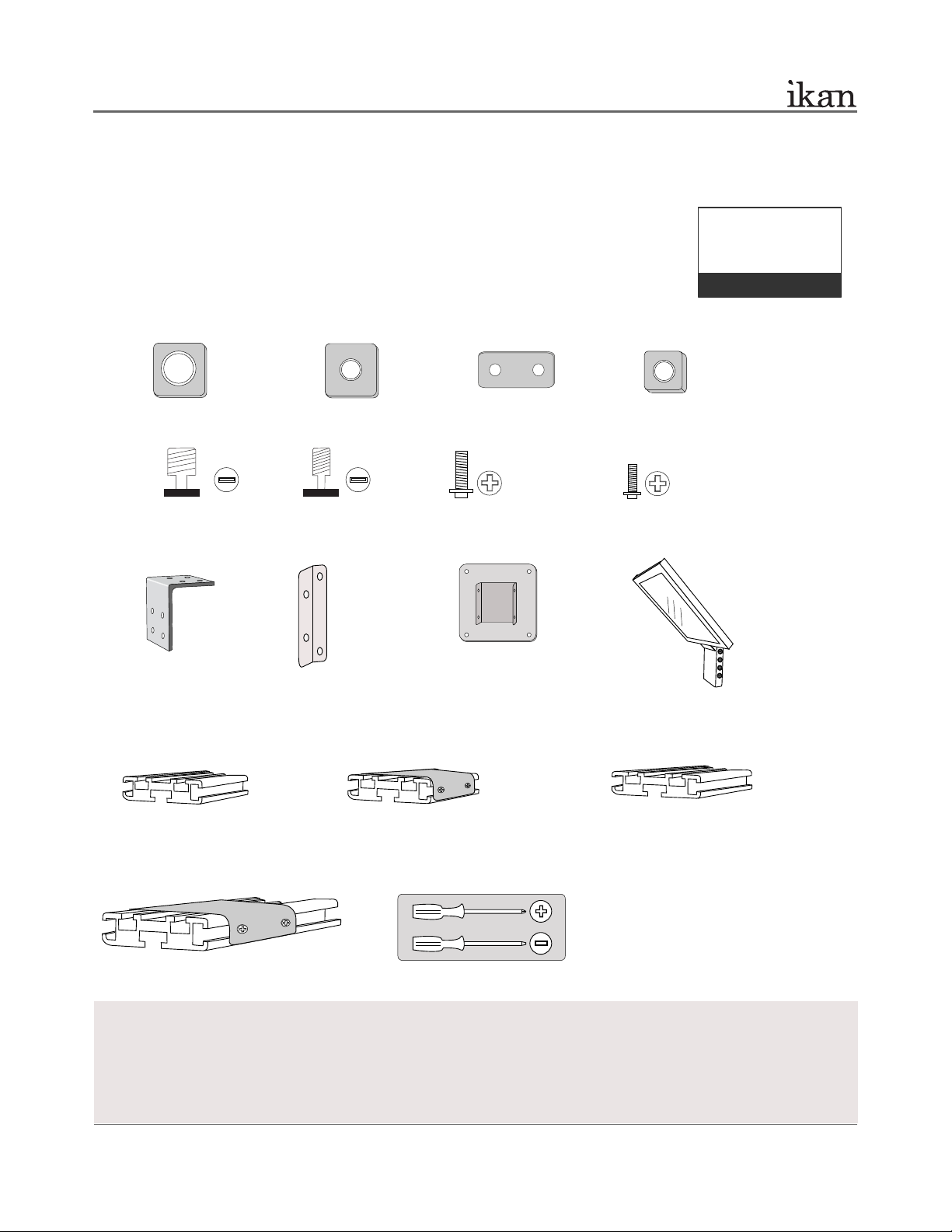
PT4000 2 0 ” TE L EPR O MPTE R
15” T-Slot
8” T-Slot
20” T-Slot with Metal Bracket
8” T-Slot with Metal Bracket
(Optional Tripod Mount)
Prompter Glass Frame
Additional Tool Needed:
** Not all parts needed for this teleprompter assembly,
depends on your camera and tripod.
2 x L-Bracket
8 x T-Slot Nut
2 x 3/8-16 Receiving Nut
2 x 1/4-20 Receiving Nut
2 x 3/8-16 Screw 2 x 1/4-20 Screw
8 x Phillips Head Screw(S)
A
B C D
M
P
N
O
I
J
K
L
E
F G H
32 x Phillips Head Screw(L)
12 x T-Plate
2 x Mounting Bracket
100mm Mounting Bracket
(for Optional Battery Mount)
INTRODUCTION
Thank you for purchasing the ikan PT4000 20” Teleprompter. The PT4000 is easy to use and will quickly become an integral part
of your studio. For more information on this and many other innovative ikan products, please visit our website:
www.ikancorp.com.
PACKAGE INCLUDES
20” LCD Monitor Kit (includes AC Adapter and Power Cord)
Prompter Hood Kit (includes 2 piece hood and 3 velcro strips)
PrompterPro Software
User Guide
Teleprompter Parts:
Checked by
CONDITIONS OF WARRANTY SERVICE
• Free service for one year from the day of purchase if the problem is caused by manufacturing errors.
• The components and maintenance service fee will be charged if the warranty period has expired.
Free Service will not be Provided in the Following Situations:
(* Even if the product is still within the warranty period.)
• Damage caused by abuse or misuse, dismantling, or changes to the product not made by the company.
• Damage caused by natural disaster, abnormal voltage, and environmental factors etc.
1 of 10
39 03 S to ney Bro ok Dr . Ho uston TX 7 706 3 | +1 .71 3.27 2. 882 2 | ww w.i ka nco rp.c om | supp or t@i kanc or p.c om | © 20 09 i ka n C orpo ra tio n. Al l ri gh t reserv ed .
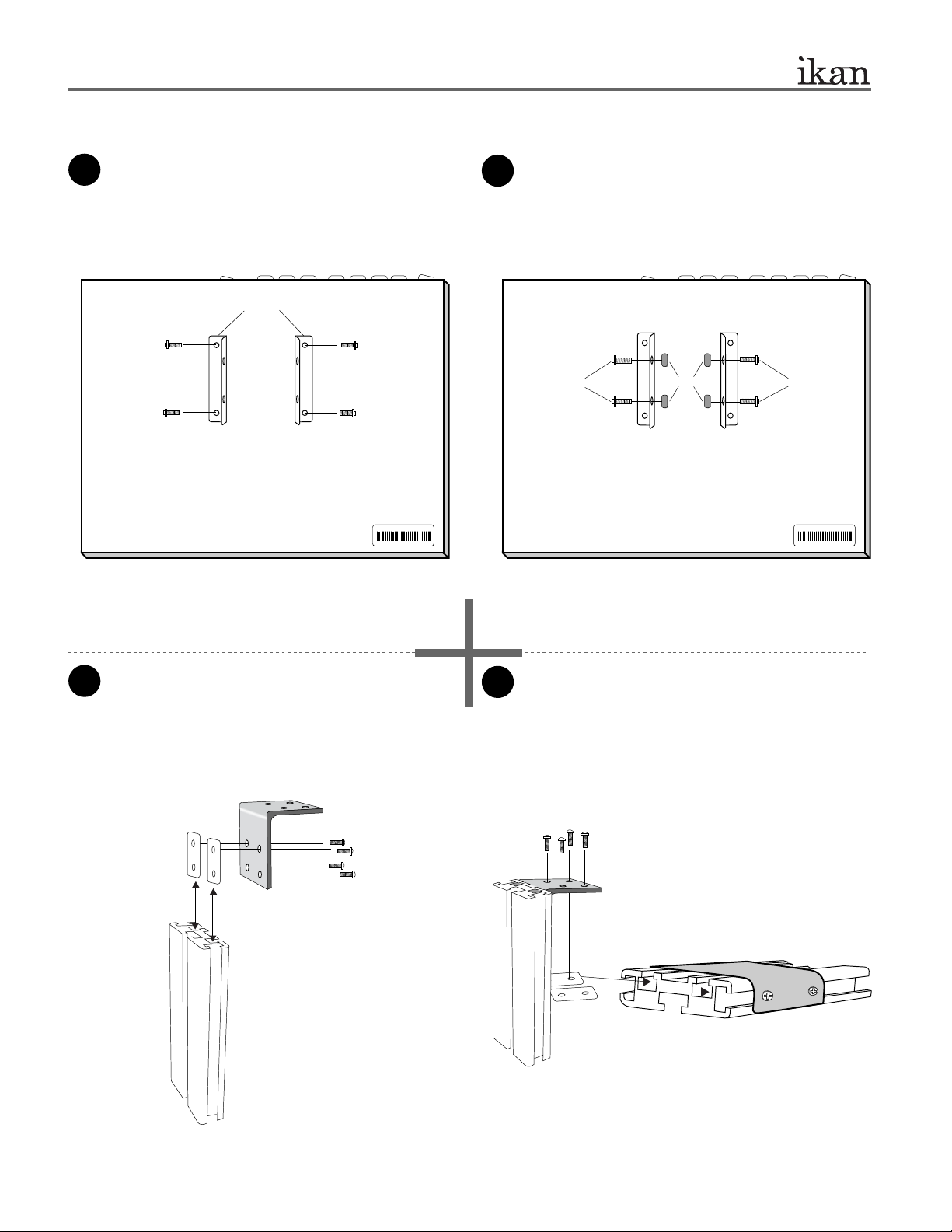
ASSEMBLY INSTRUCTION
1
3
4
2
Attach the Mounting Bracket (Part J) to the back of the 20”
monitor using 4 x Short Phillip’s head screws (Part H).
The two flaps of Part Js should be perpendicular to the
monitor control buttons.
Attach the 20” T-slot with Metal Bracket (Part P) to the
assembled parts. You will use 2 x T-plates (Part C) and
4 x Long Phillips Head screws (Part G) to do so. Make
sure to evenly tighten all screws in this assembly.
Attach 4 x T-slot Nuts (Part D) and 4 x Long Phillips Head
Screws (Part G) as shown on the diagram.
PT4000 20” TELE P R OMPT E R
Part-I
Part-M
Part P
Attach L-Bracket (Part I) to 8” T-slot (Part M) using 2 x
T-plates (Part C) and 4 x Long Phillips head screws (Part
G). Refer to illustration below for configuration. The
L-Bracket’s (Part I) top half should be flush with the
edge of the 8” T-slot (Part M). Arrange the long section
of Part I attached to Part M.
Part-G
Part-G
Part-C
Part-C
PT4000
Rear view of 20” monitor
PT4000
Rear view of 20” monitor
Part-D
Part-G Part-G
Part-H
Part-H
Part-J
+
+
+
+
Note: Do not completely tighten any screws until you have positioned
the monitor on the T-Slot.
Note: Make sure to tighten the
Long Phillips head screws down
as tight as possible. This will
support the weight of the monitor.
2 of 10
39 03 S to ney Bro ok Dr . Ho uston TX 7 706 3 | +1 .71 3.27 2. 882 2 | ww w.i ka nco rp.c om | supp or t@i kanc or p.c om | © 20 09 i ka n C orpo ra tio n. Al l ri gh t reserv ed .
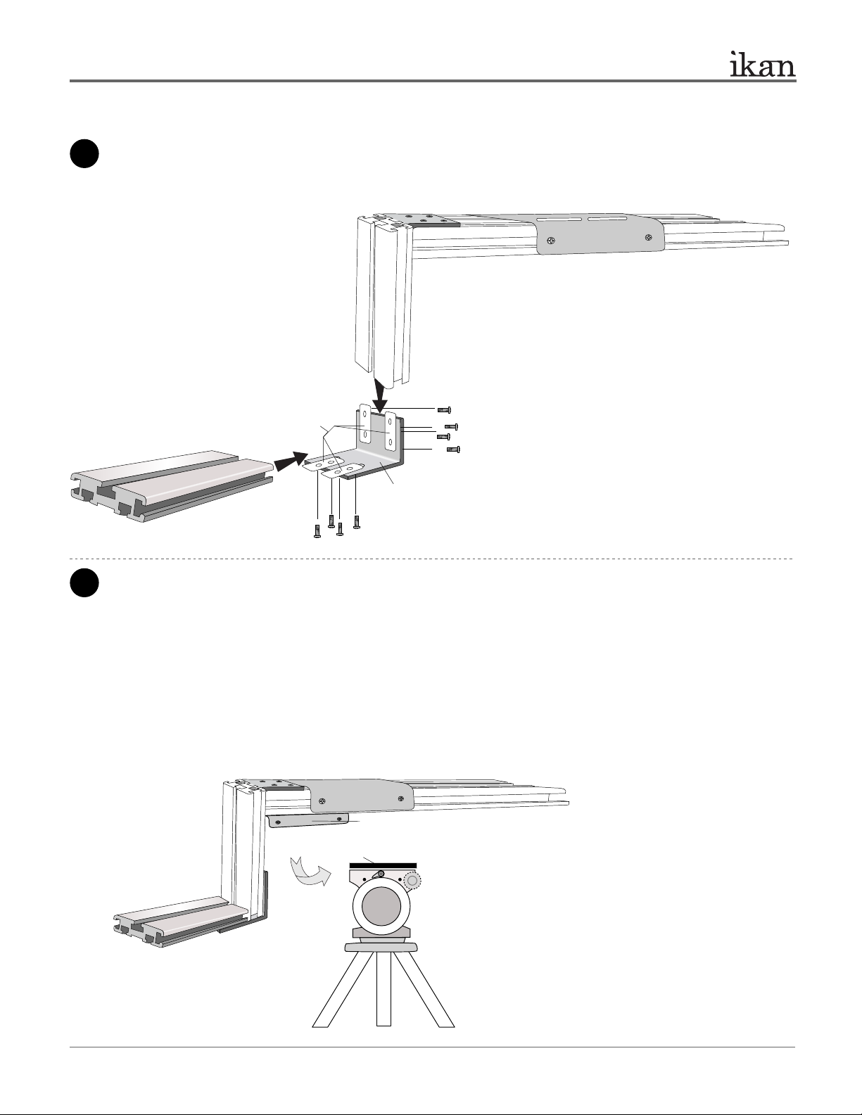
ASSEMBLY INSTRUCTION
5
6
Attach another L-Bracket (Part-J) to the assembled parts. Make sure to arrange the long section of Part J as shown in the
illustration, otherwise there will not be adequate room to place the monitor. You will use 4 x Long Phillips head screws
(Part-G) and 2 x T-plates (Part-C) to attach it. Then, you will use 4 x Long Phillips head screws (Part-G) and 2 x T-plates
(Part-C) to attach the 15” T-slot (Part-O). Make sure to evenly tighten all screws in the assembly.
PT4000 20” TELE P R OMPT E R
Part-O
Part-G
Part-G
Part-C
Part-J
ikancorp.com
Attach your tripod skid plate to Part-N.
For those who use a tripod that is rear loading (ie: your tripod skid plate slides into the tripod head from the rear), we have provided an
optional piece , Part-N, will allow for more convenient attaching and detaching of the PT4000 Teleprompter on your tripod.
> Loosen the screws and slide out the Metal Bracket
through the channels
> Install 2 x Part-A & Part-E or 2 x Part-B & Part-F
> Slide in the Metal Bracket through the single channel
of the bottom of the Part-P
> Attach your tripod skid plate to the remaining Part-N (8” T-Slot)
and secure them on your tripod head
> Attach the assembled teleprompter to your tripod
your
tripod
Part-N (Metal Bracket)
Part-N (8” T-Slot)
ikancorp.com
Important Note: Your tripod or pedestal should be a heavy-duty
grade. The PT4000 is a heavy studio teleprompter and many
tripods may not be able to hold the weight of it. Be sure that your
tripod and head can handle it.
3 of 10
 Loading...