

Page 1
MR7
MR7 HDMI LCD Monitor QUICKSTART GUIDE
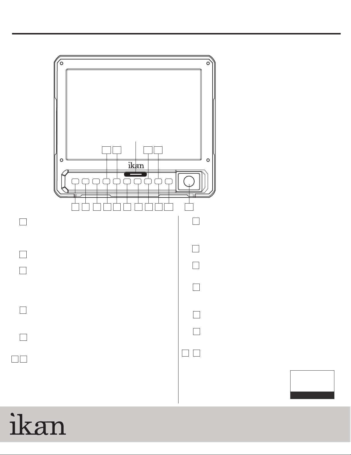
Front view
Tally Indicator Light
1 2 3 4 5 6 7 8 9 10 11
INPUT
1
Selects input signal. It will be switching as follows : SDI -> CVBS -> HDMI
Use OSD menu to select 3G signals input on SDI channel
For CVBS(Analog Composite) input, Only 1 Loop-through
output is clearly watchable.
MARKER
2
Marker On/Off
3
ZOOM
Switch zoom mode in the order of : Pixel to Pixel, User Zoom
(adjustable by up/down knob), 5D Mark II Zoom.
Please get noticed that a dot might not be shown on
SDI 720p format in some case.
WF / VS
4
Switch WF/VS display in the order of : Waveform, Vectorscope,
Waveform/Vectorscope, Wide Waveform, Full Waveform,
Full Vectorscope, and WF/VS Off.
Daylight
5
Switch the backlight luminance to : Indoor (Normal),
Outdoor (Brighter), Daylight (Brightest).
7
Function Keys (F1, F2)/SLOW/ CMD
6
Execute the function assigned by the user. A function can be
assigned for each function button.
SLOW: Change playback speed slower between 1/2 to 1/8 speed.
CMD: Opens the command dialog of the list menu.
(Selectable commands are Delete/Copy/Format/Rename/Auto Naming)
On playback of a recorded le, this button works as info On/Off,
Volume Setting or Delete button.
Parts included:
MR7
1 x MR7 Monitor
1 x Shoe mount
1 x LCD Cleaning Cloth
1 x AC Power Supply
12131415
LIST/Q-Play
8
When press and hold for 2 seconds: Enter to the Playback List Screen.
Q_PLAY : Play the latest recorded le. The latest le information
is lost when the monitor turns off.
MENU
9
Opens the OSD menu
REC
10
Start recording
Knob KEY
11
Brightness, Contrast, Chroma, Phase is adjustable by pressing knob
in general. On OSD menu or Playback, knob is used to move
cursor, select le, or press Ok.
STOP
12
Stops recording / playback on recorder mode.
DEL
13
Delete a selected le..
SEL/SEL.ALL
1415
Select one or all recorded clips on the list screen.
Checked by
www.ikancorp.com
3903 Stoney Brook Dr. Houston TX 77063
1.713.272.8822
© 2010 ikan Corporation. All right reserved
Page 2
MR7
MR7 HDMI LCD Monitor QUICKSTART GUIDE
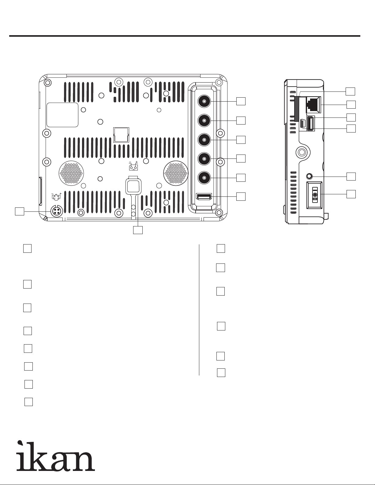
Rear view
Side view
9
2
3
10
11
12
4
5
6
7
13
14
1
8
DC power input terminal
1
It supplies DC power. Please check DC rated input voltage.
For DC Adaptor, it can be used from about
7V to 24V for 12V, Battery power.
SDI 1 input terminal (BNC)
2
It is HD/SD-SDI signal input terminal. It is SMPTE standard
method, SDI signal input which includes Audio signal is available.
SDI-LOOP OUT TERMINAL (BNC)
3
An output terminal that displays the input signal of HD/SD-SDI.
It is not displayed when the power of monitor is off. (Active Select Output)
CVBS (Composite) INPUT TERMINAL (BNC)
4
CVBS(Composite) signal input is practicable.
CVBS (Composite) OUT TERMINAL (BNC)
5
Output terminal that displays the input signal of CVBS(Composite).
HDMI to SDI Converter Output Terminal (BNC)
6
It converts the input signal as HDMI to SDI and displays.
HDMI INPUT TERMINAL (HDMI Jack)
7
HDMI signal input is practicable.
INTERNAL POWER
8
it can be used from about 7V to 24V, Battery power.
9
SD Card Slot
Use a Class 4 or higher SDHC card
REMOTE Port (RJ-45 Jack)
10
An external Make/Trig type control port
Please refer to “7. Remote Terminal Assignment
UPDATE Port (USB Port)
11
A communication terminal to update rmware.
On Firmware Update mode, DAYLIGHT, F1 button
LEDs will be blinking one by one, and 'Update Mode'
will be displayed on the bottom left of the screen
PGM/UPDATE Port (Mini USB Jack)
12
A communication terminal to update rmware, control with
Wall System Controller, or adjust color temperature. Please refer
to the “8. Program Update Port Instruction Manual” for details.
Headphone Jack
13
A stereo headphone is connectable to monitor the audio.
Power selection switch
14
Internal Power, OFF, External Power are selectable.
www.ikancorp.com 713-272-8822
 Loading...