

Page 1
20000006119
RV 8_072017
IKA® RV 8
Betriebsanleitung DE 04
Ursprungssprache
Operating instructions EN 21
Mode d‘emploi FR 38
Руководство пользователя RU 55
使用说明 ZH 72
Indicationes de seguridad ES 123
Veiligheidsinstructies NL 125
Norme di sicurezza IT 127
Säkerhetsanvisningar SV 129
Sikkerhedshenvisninger DA 131
Sikkerhetsanvisninger NO 133
Turvallisuusohjeet FI 135
Normas de segurança PT 137
Wskazówki bezpieczeństwa PL 139
取扱説明書
JA 89
사용 설명서
Bezpečnostní pokyny CS 141
Biztonsági utasitások HU 143
Varnostna opozorila SL 145
Bezpečnostné pokyny SK 147
Ohutusjuhised ET 149
Drošības norādes LV 151
Nurodymai dėl saugumo LT 153
Инструкции за безопасност BG 155
Indicaţii de siguranţă RO 157
Υποδείξείς ασφάλείας EL 159
KO 106
Page 2
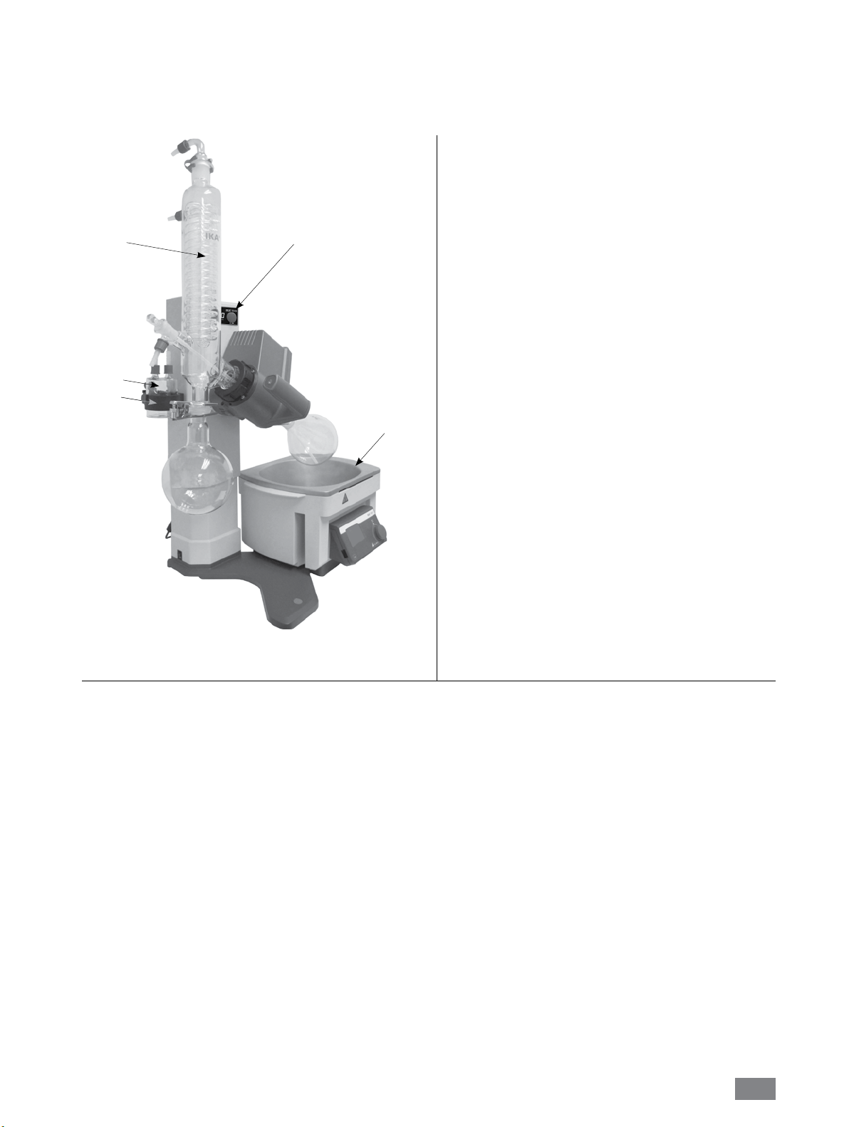
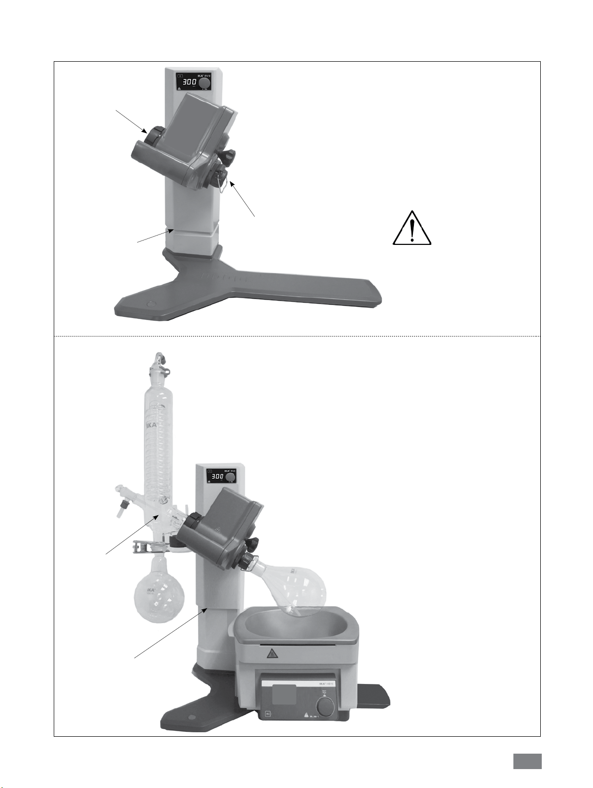
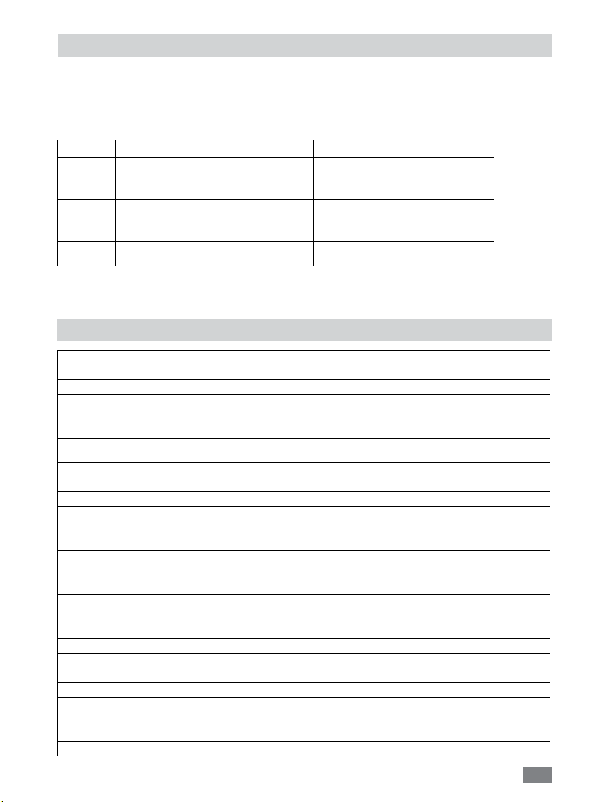
Pos. Bezeichung
A RV 8 Antrieb
B HB 10 Heizbad
C Halter
D Woulff’sche Flasche
E Glassatz
C
E
D
A
Item Designation
A RV 8 drive
B HB 10 heating bath
C Bracket
D Woulff bottle
E Glassware
Pos Désignation
B
Fig. 2
A RV 8 Entraînement
B HB 10 Bain chauffant
C Support
D Flacon de Woulfe
E Verrerie
Нет. обозначение
A RV 8 ездить
B HB 10 нагревательной бани
C Кронштейн
D Woulff бутылки
E стекло
序号 名称
A RV 8 主机
B HB 10 加热锅
C 真空缓冲回流瓶支架
D 真空缓冲回流瓶
E 玻璃组件
品目 名称
A RV 8 駆動部
B HB 10 ヒ ー ティング バ ス
C 金具
D ウルフ瓶
E ガラス製品
일련 번호 이름
A RV 8 컨크롤 판넬
B HB 10 가열 수조
C 울프바틀 비이커 홀더
D 울프바틀 비이커
E 냉각콘덴스
2
Page 3
4
1
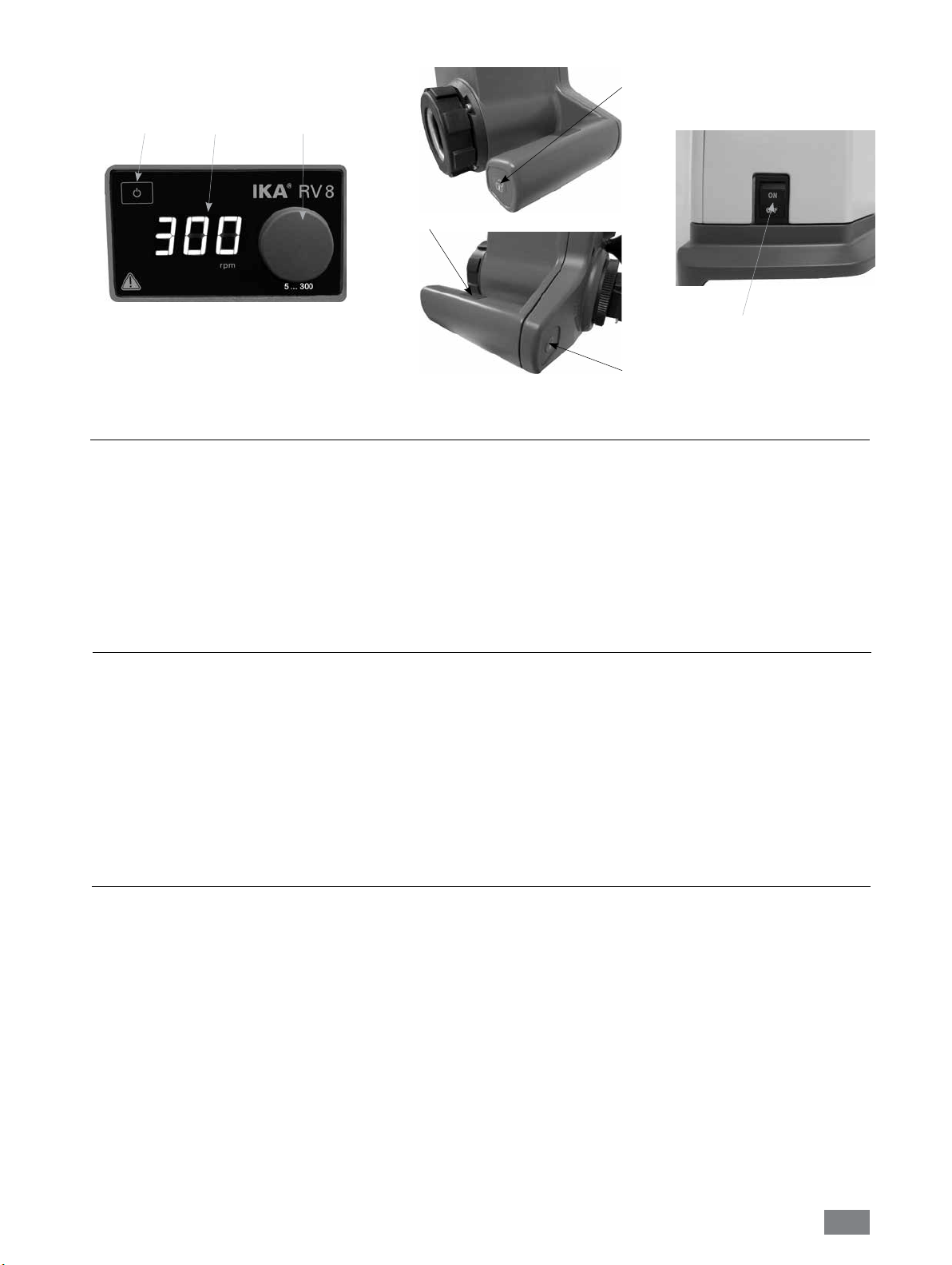
Funktion Tasten:
Pos. Bezeichnung
1 Taste „Power“
2 Anzeige/Geschwindigkeit
3 Drehknopf Geschwindigkeit/
Drehantrieb „START/STOP“
4 Taste „Lift lock“
5 Netzschalter
6 Handerkennungs-Sensor
2
3
Fig.3
6
Function Keys:
Item Designation
1 “Power“ key
2 Display window/speed
3 Rotating knob speed/
Rotation drive “START/STOP“
4 “Lift lock“ key
5 Power Switch
6 Hand detection sensor
Fig.4a
Fig.5
5
4
Fig.4b
Touches de fonction:
article Désignation
1 „Power“ clé
2 Fenêtre d‘affichage / vitesse
3 vitesses bouton rotatif /
commande de rotation „START/STOP“
4 „Lift lock“ bouton
5 Interrupteur d‘alimentation
6 Capteur de détection de main
Функциональные клавиши:
Нет. обозначение
1 „Power“ ключ
2 показывать / скорость
3 Вращающийся регулятор скорости /
Вращение диска „START/STOP“
4 „Lift lock“ кнопка
5 Выключатель питания
6 Датчика определения рук
기능 키:
일련 번호 이름
1 “전원”버튼
2 윈도우/속도 표시
디지털 화면
3 회전 속도 조절 노브
회전 “시작/정지”
4 “리프트 잠금” 키
5 메인 전원스위치
6 손 감지 센서
功能按键:
序号 名称
1 电源开关薄膜按键
2 屏幕窗口/显示转速
3 调速旋钮/
旋转驱动开关
4 升降系统锁定按键
5 电源开关按钮
6 触摸感应键
機能キー:
品目 名称
1 「電源」キー
2 ディスプレイ/ 速度
3 回転つまみ速度/
回転駆動“START/STOP“
4 昇降位置キー
5 オ ン・オ フ ス イ ッ チ
6 手検出センサー
3
Page 4
Ursprungssprache
DE
Inhaltsverzeichnis
EU - Konformitätserklärung 4
Zeichenerklärung 4
Sicherheitshinweise 4
Bestimmungsgemäßer Gebrauch 8
Auspacken 8
Wissenswertes 9
Aufstellung 9
Antrieb RV 8
Glassatz
Verschlauchung
Heizbad
Seite
Inbetriebnahme 14
Montage des Statives RV 8.1 15
Wartung und Reinigung 16
Zubehör 16
Fehlercodes 19
Technische Daten 19
Lösemitteltabelle (Auswahl) 20
Gewährleistung 20
EU - Konformitätserklärung
Wir erklären in alleiniger Verantwortung, dass dieses Produkt den Bestimmungen der Richtlinien 2014/35/EU, 2006/42/EG, 2014/30/EU
und 2011/65/EU entspricht und mit den folgenden Normen und norminativen Dokumenten übereinstimmt: EN 61010-1, EN 61010-2051; EN 61326-1 und EN 12100.
Zeichenerklärung
Allgemeiner Gefahrenhinweis.
Mit diesem Symbol sind Informationen gekennzeichnet, die für die Sicherheit Ihrer Gesundheit von
GEFAHR
WARNUNG
VORSICHT
GEFAHR
absoluter Bedeutung sind. Missachtung kann zur Gesundheitsbeeinträchtigung und Verletzung führen.
Mit diesem Symbol sind Informationen gekennzeichnet, die für die technische Funktion des Gerätes von
Bedeutung sind.
Missachtung kann Beschädigungen am Gerät zur Folge haben.
Mit diesem Symbol sind Informationen gekennzeichnet, die für den einwandfreien Ablauf der Geräte-
funktion sowie für den Umgang mit dem Gerät von Bedeutung sind. Missachtung kann ungenaue
Ergebnisse zur Folge haben.
GEFAHR - Hinweis auf die Gefährdung durch eine heiße Oberfläche.
Sicherheitshinweise
Zu Ihrem Schutz
Die Sicherheitsanhebung bei Stromausfall
und Ausschalten des Gerätes ist für das
Anheben des Liftes mit montiertem Glassatz
ausgelegt. Beachten Sie daher, daß der Lift
ohne Glasaufbauten aufgrund des reduzierten
Gewichtes schnell nach oben fährt.
Lesen Sie die Betriebsanleitung vor Inbetriebnahme
•
vollständig und beachten Sie die Sicherheitshinweise.
• Bewahren Sie die Betriebsanleitung für Alle zugänglich auf.
• Beachten Sie, dass nur geschultes Personal mit dem Gerät arbeitet.
• Beachten Sie die Sicherheitshinweise, Richtlinien, Arbeitsschutz
und Unfallverhütungsvorschriften. Insbesondere bei Arbeiten
unter Vakuum!
Tragen Sie Ihre persönliche Schutzausrüstung entsprechend der
•
Gefahrenklasse des zu bearbeitenden Mediums. Ansonsten
besteht eine Gefährdung durch:
- Spritzen von Flüssigkeiten
- Erfassen von Körperteilen, Haaren, Kleidungsstücken
und Schmuck.
- Verletzung durch Glasbruch.
4
Page 5
GEFAHR
• Stellen Sie das Gerät frei auf einer ebenen, stabilen, sauberen,
rutschfesten, trockenen, und feuerfesten Fläche auf.
• Achten Sie auf genügende Höhenfreiheit, da der Glasaufbau die
Gerätehöhe überschreiten kann.
• Prüfen Sie vor jeder Verwendung Gerät, Zubehör und
insbesondere Glassteile auf Beschädigungen. Verwenden Sie
keine beschädigten Teile.
• Achten Sie auf einen spannungsfreien Glasaufbau! Berstgefahr
durch:
- Spannungen infolge von fehlerhaftem Zusammenbau;
- mechanische Einwirkungen von außen;
- durch örtliche Temperaturspitzen.
• Achten Sie darauf, dass das Gerät aufgrund von Vibrationen
bzw. Unwucht nicht zu wandern beginnt.
• Beachten Sie eine Gefährdung durch:
- entzündliche Materialien;
- brennbare Medien mit niedriger Siedetemperatur;
- Glasbruch.
VORSICHT
• Betreiben Sie das Gerät nicht in explosionsgefährdeten
Atmosphären, mit Gefahrstoffen und unter Wasser.
• Bearbeiten Sie nur Medien, bei denen der Energieeintrag durch
das Bearbeiten unbedenklich ist. Dies gilt auch für andere
Energieeinträge, z.B. durch Lichteinstrahlung.
• Arbeiten mit dem Gerät dürfen nur im überwachten Betrieb
durchgeführt werden.
• Der Betrieb mit Überdruck ist nicht zulässig (Kühlwasserdruck
siehe „Technische Daten”).
• Decken Sie die Lüftungsschlitze zur Kühlung des Gerätes nicht
zu.
• Zwischen Medium und Antriebseinheit können elektrostatische
Vorgänge ablaufen und zu einer Gefährdung führen.
• Das Gerät ist nicht für den Handbetrieb geeignet. (Ausnahme
Hubbewegung).
• Sicheres Arbeiten ist nur mit Zubehör, das im Kapitel „Zubehör”
beschrieben ist, gewährleistet.
• Beachten Sie die Betriebsanleitung des Heizbades HB 10.
• Beachten Sie die Betriebsanleitung des Zubehörs z.B.
Vakuumpumpe.
• Verlegen Sie den druckseitigen Ausgang der Vakuumpumpe in
den Laborabzug.
• Betreiben Sie das Gerät nur unter einem allseitig geschlossenen
Abzug oder vergleichbaren Sicherheitseinrichtungen.
• Passen Sie die Menge und Art des Destillationsgutes an die Größe
der Destillationsapparatur an. Der Kühler muss ausreichend
wirksam sein. Überwachen sie den Kühlmitteldurchfluss am
Ausgang des Kühlers.
• Belüften Sie immer den Glasaufbau bei Arbeit unter Normaldruck
(z.B. offener Ausgang am Kühler), um einen Druckaufbau zu
verhindern.
Beachten Sie eine Gefährdung des
Anwenders durch Kontakt oder
Einatmen von Medien, z.B. giftige
Flüssigkeiten, Gase, Nebel, Dämpfe
oder Stäube oder biologische bzw.
mikrobiologische Stoffe.
Mit diesem Gerät dürfen nur Medien
bearbeitet bzw. erhitzt werden, deren
Flammpunkt über der eingestellten
Sicherheitstemperaturbegrenzung
des Heizbades liegt. Die eingestellte
Sicherheitstemperaturbegrenzung des
Heizbades muss immer mindestens 25
°C unterhalb des Brennpunktes des
verwendeten Mediums liegen.
• Beachten Sie, dass Gase, Dämpfe oder Schwebstoffe in
gefährlicher Konzentration durch den offenen Ausgang
am Kühler entweichen können. Stellen Sie sicher, dass eine
Gefährdung ausgeschlossen ist, z.B. durch nachgeschaltete
Kühlfallen, Gaswaschflaschen oder eine wirksame Absaugung.
• Erhitzen Sie evakuierte Glasgefässe nicht einseitig. Der
Verdampferkolben muss während der Heizphase rotieren.
• Der Glassatz ist für einen Vakuumbetrieb bis zu 2 mbar ausgelegt.
Evakuieren Sie die Apparaturen vor Beginn des Aufheizens
(siehe Kapitel „Inbetriebnahme”). Belüften Sie die Apparaturen
erst wieder nach dem Abkühlen. Nicht kondensierte Dämpfe
müssen auskondensiert oder gefahrlos abgeführt werden.
Besteht die Gefahr, dass sich der Destillationsrückstand in
Gegenwart von Sauerstoff zersetzt, darf nur Inertgas zum
Entspannen eingelassen werden.
VORSICHT
GEFAHR
WARNUNG
Vermeiden Sie Peroxidbildung. In den
Destillations und Abdampfrückständen
können sich organische Peroxide
anreichern und explosionsartig
zersetzen! Bewahren Sie Flüssigkeiten
die zur Bildung organischer Peroxide
neigen, vor Licht - insbesondere
UV-Strahlung - geschützt auf und
untersuchen Sie sie vor der Destillation
und dem Abdampfen auf Anwesenheit
von Peroxiden. Vorhandene Peroxide
müssen entfernt werden. Zur Bildung
von Peroxiden neigen zahlreiche
organische Verbindungen, z.B. Dekalin,
Diethylehter, Dioxan, Tetrahydrofuran,
ferner ungesättigte Kohlenwasserstoffe,
wie Tetralin, Diene, Cumol sowie
Aldehyde, Ketone, und Lösungen dieser
Stoffe.
Das Heizbad, das Temperiermedium
sowie der Verdampferkolben und
Glasaufbau können während dem
Betrieb und längere Zeit danach heiß
sein! Lassen Sie die Komponenten vor
weiteren Arbeiten am Gerät abkühlen.
Vermeiden Sie Siedeverzug. Das
Aufheizen des Verdampferkolbens
im Heizbad ohne Zuschalten des
Rotationsantriebes ist nicht zulässig!
Zeigen sich durch plötzliches
Schäumen oder Ausgasen Anzeichen
für eine beginnende Zersetzung
des Kolbeninhaltes, schalten Sie
sofort die Beheizung aus. Heben Sie
den Verdampferkolben durch die
Hubvorrichtung aus dem Heizbad.
Räumen Sie den gefährdeten Bereich
und warnen Sie die Umgebung!
5
Page 6

Sicherheitsanhebung
Durch Abschalten des Gerätes oder durch Trennen der
Stromversorgung tritt die interne Sicherheitsanhebung in Kraft
und hebt den Verdampferkolben aus dem Heizbad.
Die Sicherheitsanhebung im stromlosen Zustand ist für ein
maximales Gesamtgewicht (Glassatz plus Lösemittel) von 3,1 kg
ausgelegt.
Beispiel für die Berechnung der max. Zuladung bei einem vertikalen
Glassatz mit 1 Liter Kolben:
Kühler + Auffangkolben + Verdampferkolben + Kleinteile=
1200 gr + 400 gr + 280 gr + 100 gr = 1980 gr
Maximale Zuladung an Lösemittel = 3100 gr – 1980 gr = 1120 gr
Eine Sicherheitsanhebung bei höheren Zuladungen kann
bauartbedingt nicht sichergestellt werden!
Bei Verwendung anderer Kühlerarten wie z.B. Trockeneis- oder
Intensivkühler, sowie bei Verwendung von Rückflussdestillationsverteilerstücken mit Aufsteck kühler kann es notwendig sein, die
Zuladung entsprechend dem Mehrgewicht dieser Glasaufbauten
zu reduzieren!
Überprüfen Sie deshalb vor Destillationsbeginn, ob der mit
Glassatz und Destillationsgut bestückte Lift im stromlosen Zustand
nach oben fährt.
Die Sicherheitsanhebung muss vor dem Betrieb täglich überprüft
werden.
Fahren Sie den Lift, bestückt mit dem maximalen Gesamtgewicht
von 3,1 kg manuell in die untere Endlage und betätigen Sie die
„Power“ Taste auf dem Frontschild oder den Netzhauptschalter an
der linken Geräteseite.
Der Verdampferkolben wird aus dem Heizbad gehoben.
Sollte die Sicherheitsanhebung nicht funktionieren, kontaktieren
Sie bitte die IKA
Verdampferseitig (Verdampferkolben plus Inhalt) beträgt das
maximale zulässige Gewicht 3,0 kg ! Größere Zuladungen bergen
die Gefahr von Glasbruch am Dampfdurchführungsrohr!
Beachten Sie, dass hierbei die Sicherheitsanhebung ausser Kraft
gesetzt ist.
Arbeiten Sie bei großen Zuladungen immer mit langsamen
Drehzahlen. Große Unwuchtskräfte führen zum Bruch des
Dampfdurchführungsrohres !
®
- Serviceabteilung.
• Unterdruck im Glassatz nach Stromausfall möglich! Der Glassatz
muss manuell belüftet werden.
Betreiben Sie das Gerät niemals mit
VORSICHT
Stellen Sie die Drehzahl des Antriebes so ein, dass durch
•
den drehenden Verdampferkolben im Heizbad kein
Temperiermedium herausgeschleudert wird und reduzieren Sie
gegebenenfalls wieder die Drehzahl.
• Niemals in rotierende Teile fassen.
•
Unwuchten können zu unkontrolliertem Resonanzverhalten des
Gerätes, bzw. des Aufbaus führen. Glasapparaturen können
beschädigt oder zerstört werden. Schalten Sie das Gerät bei
Unwucht oder außergewöhnlichen Geräuschen sofort aus oder
reduzieren Sie die Drehzahl.
• Nach einer Unterbrechung der Stromzufuhr läuft das Gerät nicht
von selbst wieder an.
• Eine Trennung vom Stromversorgungsnetz erfolgt bei dem Gerät
nur über das Betätigen des Geräteschalters bzw. das Ziehen des
Netz - bzw. Gerätesteckers.
•
Die Steckdose für die Netzanschlussleitung muss leicht erreichbar
und zugänglich sein.
Zum Schutz des Gerätes
• Spannungsangabe des Typenschildes muss mit der Netzspannung
übereinstimmen.
• Steckdose muss geerdet sein (Schutzleiterkontakt).
•
Abnehmbare Geräteteile müssen wieder am Gerät angebracht
werden, um das Eindringen von Fremdkörpern, Flüssigkeiten etc.
zu verhindern.
• Vermeiden Sie Stöße und Schläge auf das Gerät oder Zubehör.
• Das Gerät darf nur von einer Fachkraft geöffnet werden.
rotierendem Verdampferkolben und
angehobenem Lift. Senken Sie immer
erst den Verdampferkolben in das
Heizbad ab und starten Sie danach den
Rotationsantrieb. Ansonsten besteht
eine Gefährdung durch Herausspritzen
von heißem Temperiermedium!
6
Page 7
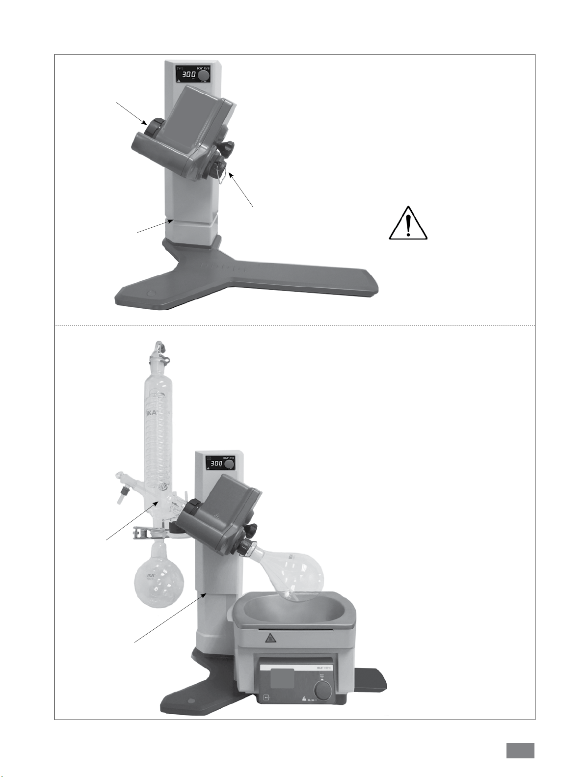
Ohne Glassatz!
Ohne Glassatz!
Untere Position!
GEFAHR!
Vorsicht! Schnelle Hubbewegung
ohne Glassatz aufgrund von integrierter Feder!
Das Gerät ausschließlich in der oberen
Position ausschalten!
Mit Vertikalkühler
und Dampfleitung!
Obere Position!
Hinweis:
Sichere Hubbewegung!
Das Gerät kann jederzeit ausge-
schaltet werden!
7
Page 8
Bestimmungsgemäßer Gebrauch
• Verwendung
Das Gerät ist in Verbindung mit dem von IKA
Zubehör geeignet für:
- schnelle und schonende Destillation von Flüssigkeiten,
- eindampfen von Lösungen und Suspensionen,
- kristallisation, Synthese oder Reinigung von Feinchemikalien,
- pulver- und Granulattrocknung,
- recycling von Lösungsmittel.
Betriebsart: Tischgerät
®
empfohlenen
• Verwendungsgebiet
- Laboratorien - Schulen
- Apotheken - Universitäten
Der Schutz für den Benutzer ist nicht mehr gewährleistet, wenn
das Gerät mit Zubehör betrieben wird, welches nicht vom
Hersteller geliefert oder empfohlen wird oder das Gerät in nicht
bestimmungsgemäßem Gebrauch entgegen der Herstellervorgabe
betrieben wird.
Auspacken
• Auspacken
- Packen Sie das Gerät vorsichtig aus
- Nehmen Sie bei Beschädigungen sofort den Tatbestand auf (Post, Bahn oder Spedition)
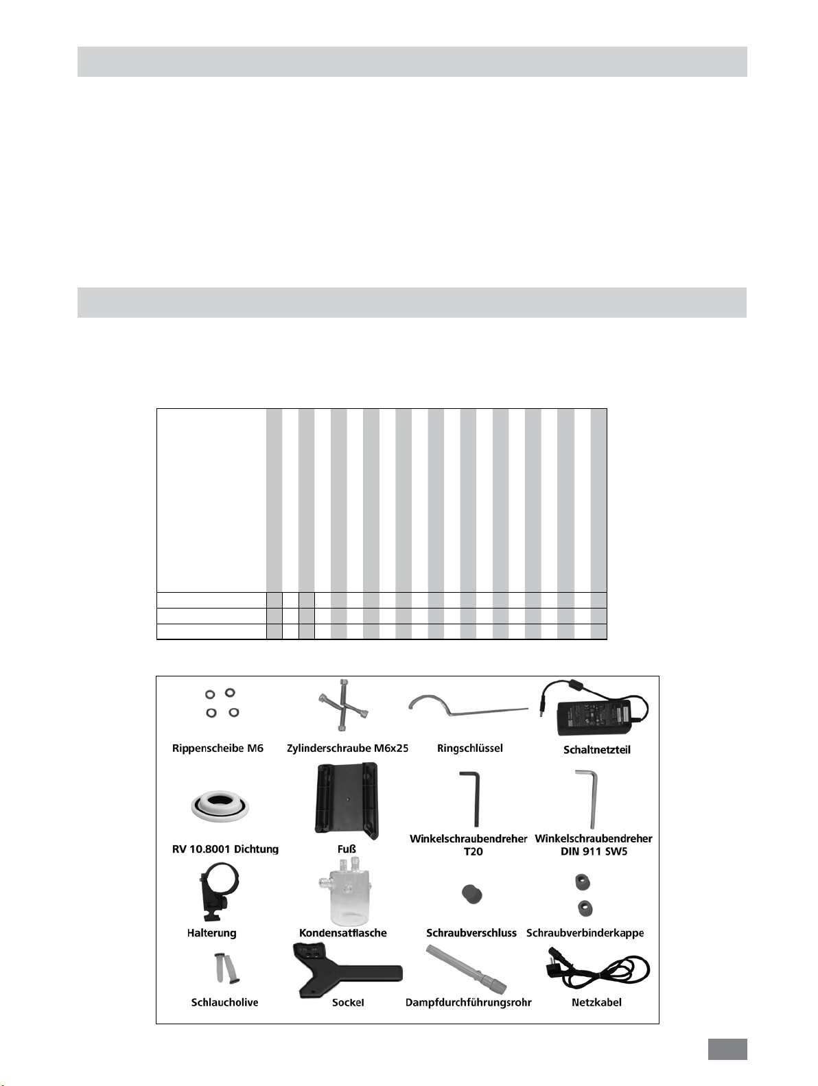
• Lieferumfang
Antrieb RV 8
Heizbad HB 10
Glassatz vertikal RV 10.1
Glassatz vertikal RV 10.10 beschichtet
Rippenscheibe M6
Zylinderschraube M6x25
Ringschlüssel
Schaltnetzteil
RV 10.8001 Dichtung
Fuß
Winkelschraubendreher T20
Winkelschraubendreher DIN911 SW5
Halterung
Kondensatflasche
Schraubverschluss
Schraubverbinderkappe
Schlaucholive
Betriebsanleitung
Sockel
Packen 1 / RV 8 V 1 1 1 4 4 1 1 1 1 1 1 1 1 1 2 2 1 1 1 2
Packen 2 / RV 8 VC 1 1 1 4 4 1 1 1 1 1 1 1 1 1 2 2 1 1 1 2
Packen 3 / RV 8 flex 1 1 4 4 1 1 1 1 1 1 1 1 1 2 2 1 1 1 2
Lieferumfang RV 8
Dampfdurchführungsrohr
Netzkabel
Fig. 6
8
Page 9
Wissenswertes
Destillation ist ein thermisches Trennverfahren für flüssige
Stoffverbindungen auf Grundlage stoffspezifischer, druckabhängiger Siedepunkte durch Verdampfen und anschließender Kondensation.
Die Siedepunkttemperatur verringert sich mit sinkendem äußerem
Druck, so dass in der Regel bei vermindertem Druck gearbeitet
wird. So kann das Heizbad bei konstanter Temperatur (z.B. 60 °C)
gehalten werden. Über das Vakuum wird nun der Siedepunkt bei
einer Dampftemperatur von ca. 40 °C eingestellt. Das Kühlwasser
für den Kondensationskühler sollte nicht wärmer als 20 °C sein
(60-40-20 Regel).
Zur Vakuumerzeugung sollte eine chemiefeste Membranpumpe
eingesetzt werden, die durch Vorschalten einer Woulff’schen Flasche und/ oder eines Vakuum-Abscheiders vor Lösemittelrückständen geschützt wird.
Das Arbeiten mit einer Wasserstrahlpumpe zur Vakuumerzeugung
kann nur bedingt empfohlen werden, da bei diesen Systemen eine
Kontamination der Umwelt durch Lösemittel stattfinden kann.
Die Verdampferleistung wird durch Drehzahl, Temperatur, Kolbengröße und Systemdruck beeinflusst.
Die optimale Auslastung des Durchlaufkühlers liegt bei ca. 60%.
Dies entspricht einer Kondensation an ca. 2/3 der Kühlwendel. Bei
größerer Auslastung besteht die Gefahr, dass nicht kondensierter
Lösemitteldampf abgesaugt wird.
VORSICHT
Bei Verwendung anderer Kühlerarten wie z.B. Trockeneis- oder
Intensivkühler, sowie bei Verwendung von Rückflussdestillationsverteilerstücken mit Aufsteckkühler kann es notwendig sein, die
Zuladung entsprechend dem Mehrgewicht dieser Glasaufbauten
zu reduzieren. Überprüfen Sie deshalb vor Destillationsbeginn,
ob der mit Glas und Destillationsgut bestückte Lift im stromlosen
Zustand nach oben fährt.
Das Gerät ist für den Betrieb an einer Kühlwasserversorgung (z.B.
Laborthermostat) ausgelegt, kann jedoch auch an der Wasserleitung betrieben werden. Beachten Sie hierzu die Technischen
Daten hinsichtlich Kühlwasserdruckkonstanz, Kühlwassertemperaturkonstanz und Durchfluss.
Das Gerät ist mit einer Lift-Sicherheitsvorrichtung ausgestattet.
Bei Stromausfall wird der Verdampferkolben durch eine integrierte Feder automatisch aus dem Heizbad angehoben.
„ACHTUNG! Die Sicherheitsanhebung
muss vor dem Betrieb täglich überprüft
werden. Siehe hierzu Kapitel Sicherheitshinweise / Sicherheitsanhebung!“
Der Glasaufbau kann nach Stromausfall
evakuiert sein!
Aufstellung
Antrieb RV 8
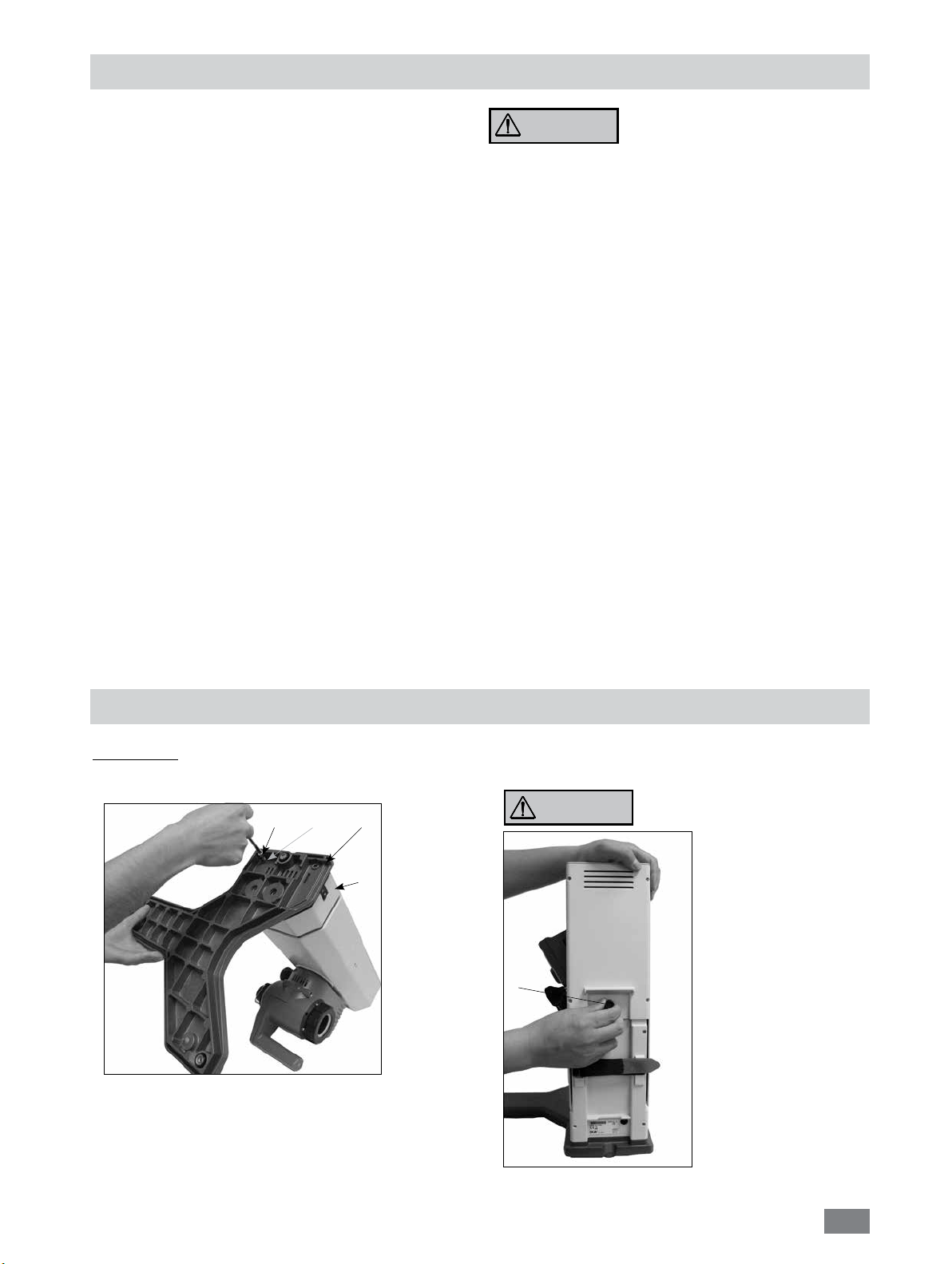
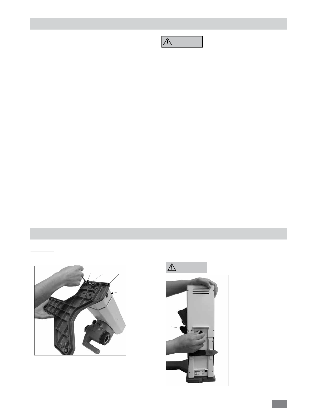
1.) Montieren des Sockels an den Lift. (Fig. 7)
F
G
H
I
Fig. 7
Befestigen Sie den Sockel (H) mit den 4 Zylinderschrauben
•
M6x25 (F) und den 4 Rippenscheiben (G) entsprechend der Abbildung am Lift (I). (Fig. 7)
2.) Entfernen der Transportsicherung. (Fig. 8)
VORSICHT
• Halten Sie den Lift mit der
Hand auf der Höhenposition
und entfernen Sie
die Rändelschraube
(J) durch Drehen im
Gegenuhrzeigersinn auf
der Geräterückseite.
J
VORSICHT ! GEFAHR !
Der Lift fährt nach Entfernen
der
Transportsicherung schnell
in seine obere Endlage. Der
Hub beträgt ca. 120 mm.
Fig. 8
9
Page 10
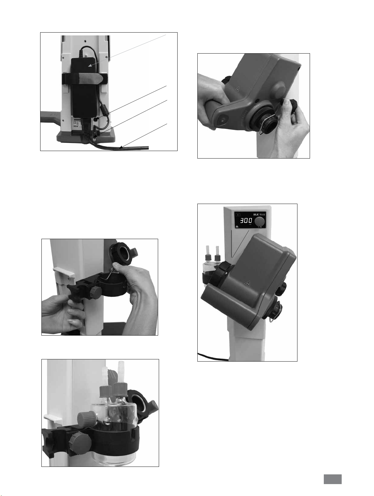
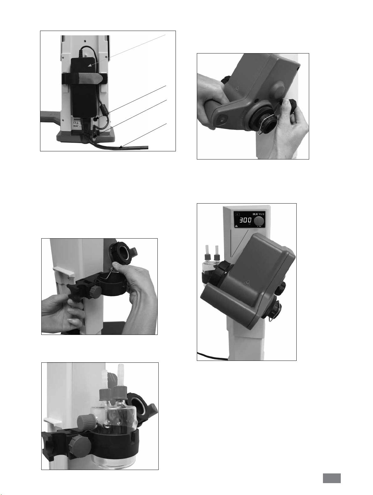
3.) Befestigen des Schaltnetzteiles. (Fig. 9)
K
N
M
L
Fig. 9
•
Befestigen Sie das Schaltnetzteil (K) auf der Geräterückseite.
Fixieren Sie es mit dem Klettverschluss, indem Sie beide Laschen
über dem Netzteil zusammenziehen. Das Klettband darf nicht
unter dem Schaltnetzteil liegen.
•
Verbinden Sie den Niederspannungsstecker (M) mit der
Anschlußbuchse (N). (Fig. 9)
• Stecken Sie das Netzkabel (L) in das Schaltnetzteil und verbinden
Sie es mit der Spannungsquelle.
• Beachten Sie die gültige Netzspannung.
6.) Verstellung des Winkels Drehkopf. (Fig. 12)
•
Lösen Sie die Klemmvorrichtung zur Winkeleinstellung des
Rotationsantriebes auf der rechten Liftseite durch Drehen des
Einstellknopfes gegen den Uhrzeigersinn.
Fig.12
7.) Stellen Sie den Antrieb auf einen Winkel von ca. 30°.
(Fig. 13)
4.) Befestigen der Kondensatflaschenhalterung. (Fig.10)
Fig.10
5.) Einsetzen der Flasche mit Schlauchanschlüsse. (Fig. 11)
30°
Fig.13
Sichern Sie anschließend den Rotationsantrieb gegen Verdrehung
•
durch Anziehen des Einstellknopfes im Uhrzeigersinn.
Fig.11
10
Page 11
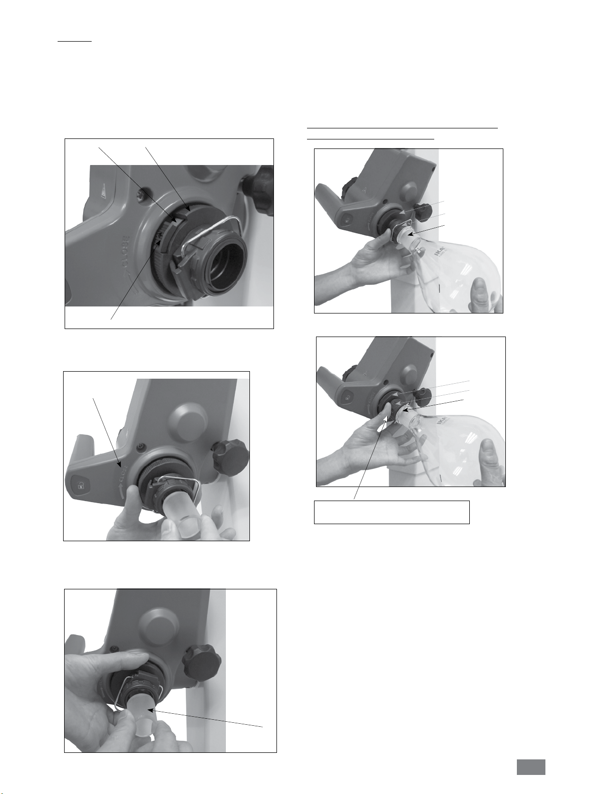
Glassatz
HINWEIS: Lesen Sie die Betriebsanleitung des Glassatzes für den
sicheren Umgang mit Laborglas.
• Der Verriegelungsknopf (P) dient zum Verriegeln oder Entriegeln
der Sicherung (O).
Wenn eine rote Markierung (Q) angezeigt wird, ist die Sicherung
entriegelt. Anderenfalls ist sie verriegelt.
Um die Sicherung zu verriegeln oder zu entriegeln (O), drücken
Sie den Verriegelungsknopf (P) zum Anschlag.
Q
O
• Wenn Sie den Verriegelungsknopf (P) zum Anschlag geschoben
haben, muss die rote Markierung (Q) verdeckt und nicht mehr
sichtbar sein.
• Das Dampfdurchführungsrohr darf nicht herausgezogen werden
können!
•
Überprüfen Sie die axiale Arretierung des Dampfdurchführungsrohres.
• Halten Sie die rote Markierung (Q) verdeckt.
Montage und Demontage des Verdampferkolbens /
Gebrauch der Abdrückvorrichtung
O
S
R
P
Fig.14a
•
Öffnen Sie die Arretierung (O) des Antriebskopf durch Drehung
um 60° gegen den Uhrzeigersinn. Anschließend wird eine rote
Markierung (Q) angezeigt.
Siehe Hinweis:
„CLOSE“
Fig.14b
• Führen Sie das Dampfdurchführungsrohr (R) bis auf Anschlag ein.
• Verriegeln Sie anschließend diese Arretierung (O) durch Drehen
um 60° im Uhrzeigersinn.
Fig.15a
O
S
T
Fig.15b
Zum Festziehen im Uhrzeigersinn drehen ()
Zum Öffnen gegen den Uhrzeigersinn drehen ()
Montieren des Verdampferkolbens:
-
Setzen Sie den Verdampferkolben auf das
Dampfdurchführungsrohr (R).
- Drehen Sie die Kunststoffmutter (P) mit der Klammer (S) gegen
den Uhrzeigersinn bis sich die Klammer über den Flansch legen
lässt. (Fig.15b)
- Drehen Sie die Kunststoffmutter nun im Uhrzeigersinn bis die
Klammer am Flansch fest anliegt. Halten Sie dazu die Arretierung
(O) des Dampfdurchführungsrohres.
(Fig.15a)
R
Fig.14c
Demontieren des Verdampferkolbens:
Halten Sie die Arretierung (O) und lösen die Kunststoffmutter
durch Drehen im Gegenuhrzeigersinn. Festsitzende
Verdampferkolben werden dadurch gelöst.
- Halten Sie den Verdampferkolben am Flansch und öffnen Sie den
Bügel der Klammer.
- Entnehmen Sie den Verdampferkolben.
- Überprüfen Sie dass die Arretierung des
Dampfdurchführungsrohres weiterhin geschlossen ist!
11
Page 12

• Setzen Sie die Dichtung RV 10.8001 (U) in die Kühleraufnahme
und montieren Sie nun den Glassatz entsprechend seiner
Betriebsanleitung an das Gerät. (Fig. 16, 17 und 18)
U
Fig.16
Fig.18
Montage Scheibe
Montieren des Kühlers
•
Schieben Sie zuerst die Kunststoffmutter und anschließend den
Federring über den Flansch des Kühlers (V).
•
Positionieren Sie den Kühler am Rotationsantrieb (W) und ziehen
Sie die Überwurfmutter handfest an. (Fig.17)
V
W
Fig.17
• Befestigen Sie den Auffangkolben und die Schlauchverbindungen,
wie dargestellt. Beachten Sie die Betriebsanleitung des
Glassatzes. (Fig.18)
Tropfkante
Hinweis: Achten Sie auf die
korrekte Lage der Scheibe.
Demontage Kühler
•
Verwenden Sie den mitgelieferten Ringschlüssel zum Lösen einer
festsitzenden Überwurfmutter.
•
Lösen Sie die Überwurfmutter durch Drehen gegen den
Uhrzeigersinn.
Beschreibung Sonderkühler
(Siehe Produkte / Zubehör zu www.ika.com)
• RV 10.3 Vertikal-Intensivkühler mit Verteilerstück
Mit Doppelmantel ausgeführter Vertikal-Intensivkühler,
ermöglicht besonders effiziente Kondensationen.
Auch in beschichteter Ausführung erhältlich (RV 10.30)
• RV 10.4 Trockeneiskühler
Trockeneiskühler zur Destillation von tiefsiedenden
Lösungsmitteln.
Kühlung durch Trockeneis, kein Kühlwasser notwendig,
maximale Kondensation durch tiefe Temperaturen.
Auch in beschichteter Ausführung erhältlich (RV 10.40)
Fig.19a
Fig.19b
12
Page 13
• RV 10.5 Vertikalkühler mit Verteilerstück und Absperrventil
für die Rückflussdestillation
Auch in beschichteter Ausführung erhältlich (RV 10.50)
•
RV 10.6 Vertikal - Intensivkühler mit Verteilerstück und
Absperrventil für die Rückflussdestillation
Mit Doppelmantel ausgeführter Vertikal - Intensivkühler,
ermöglicht besonders effiziente Rückflussdestillationen.
Auch in beschichteter Ausführung erhältlich (RV 10.60)
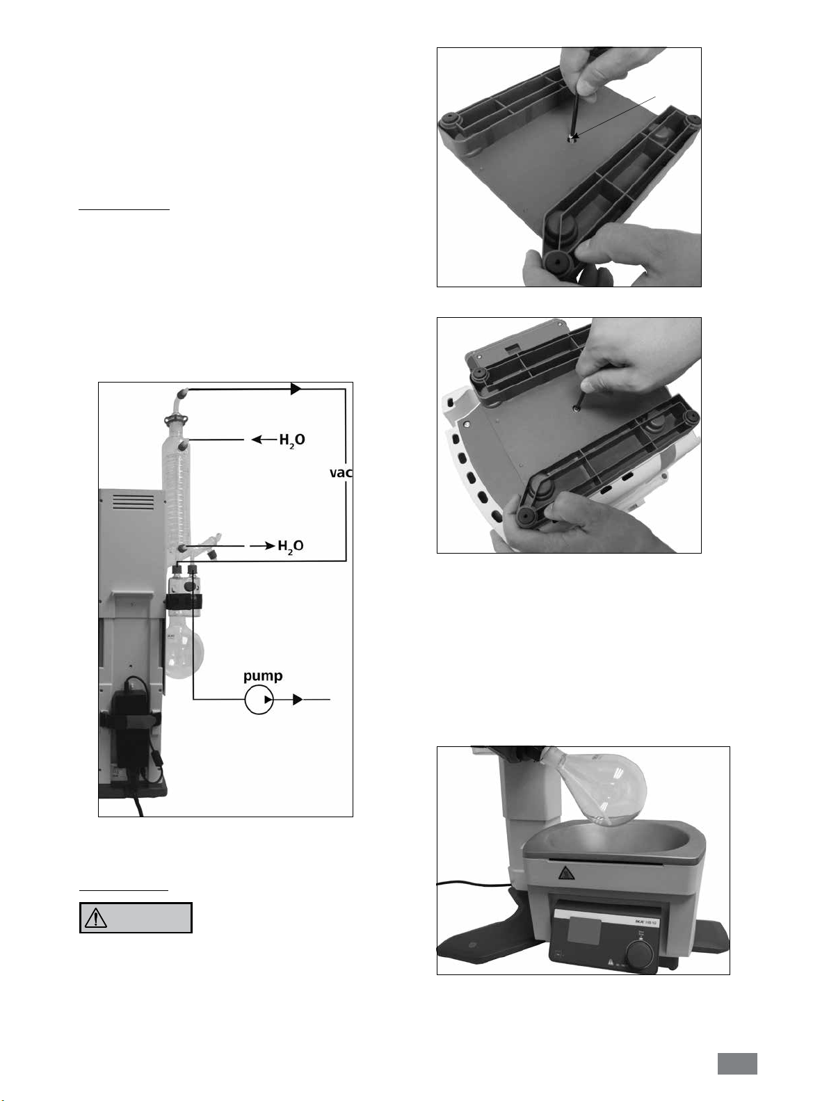
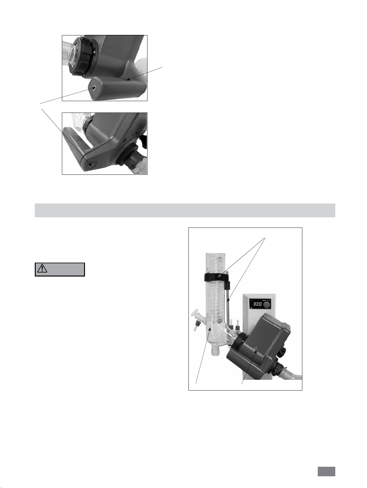
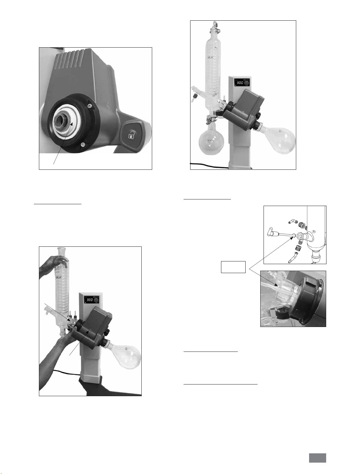
Verschlauchung
•
Schließen Sie die Wasserschläuche (H2O) nach dem
Gegenstromprinzip am Kühler an. (Fig. 20)
•
Verlegen Sie die Vakuumverbindungen zu Kühler, Woulff‘sche
Flasche, Vakuumcontroller mit Ventil sowie Vakuumpumpe.
• Schließen Sie den Vakuumschlauch (vac) am Kühler immer an
der höchsten Stelle an, um Lösemittelverluste durch Absaugen
zu vermindern.
•
Verwenden Sie hierzu laborübliche Vakuumschläuche mit
Innendurchmesser 8 mm und 5 mm Wandstärke (siehe Zubehör).
Z
Fig. 21a
Fig. 20
Heizbad HB 10
VORSICHT
• Montieren des Fußes an das Heizbad HB 10
Beachten Sie die Betriebsanleitung des
Heizbades, Kapitel
„
Inbetriebnahme”!
Fig. 21b
Drehen Sie die Schraube (Z) vollständing aus dem Fuß. (Fig.21a)
Drücken Sie den Fuß mit dem Zapfen und den daran befindlichen
O-Ringen bis auf Anschlag in die Bohrung der Bodenplatte des
Heizbades.
Ziehen Sie die Schraube (Z) handfest an. (Fig.21b)
• Stellen Sie das Heizbad auf die Stellfläche des Rotationsantriebes
und schieben sie es in die linke Position. (Fig. 22)
Für den Betrieb des Heizbades HB 10 in Kombination mit dem RV 8
die beiligende Fußplatte an das Heizbad montiert werden!
Achtung:
HB 10 in Kombination mit einem anderen Rotationsverdampfertyp ist
nicht gestattet!
Der Betrieb eines mit einer Fußplatte ausgestatteten Heizbades
muss
Fig. 22
13
Page 14
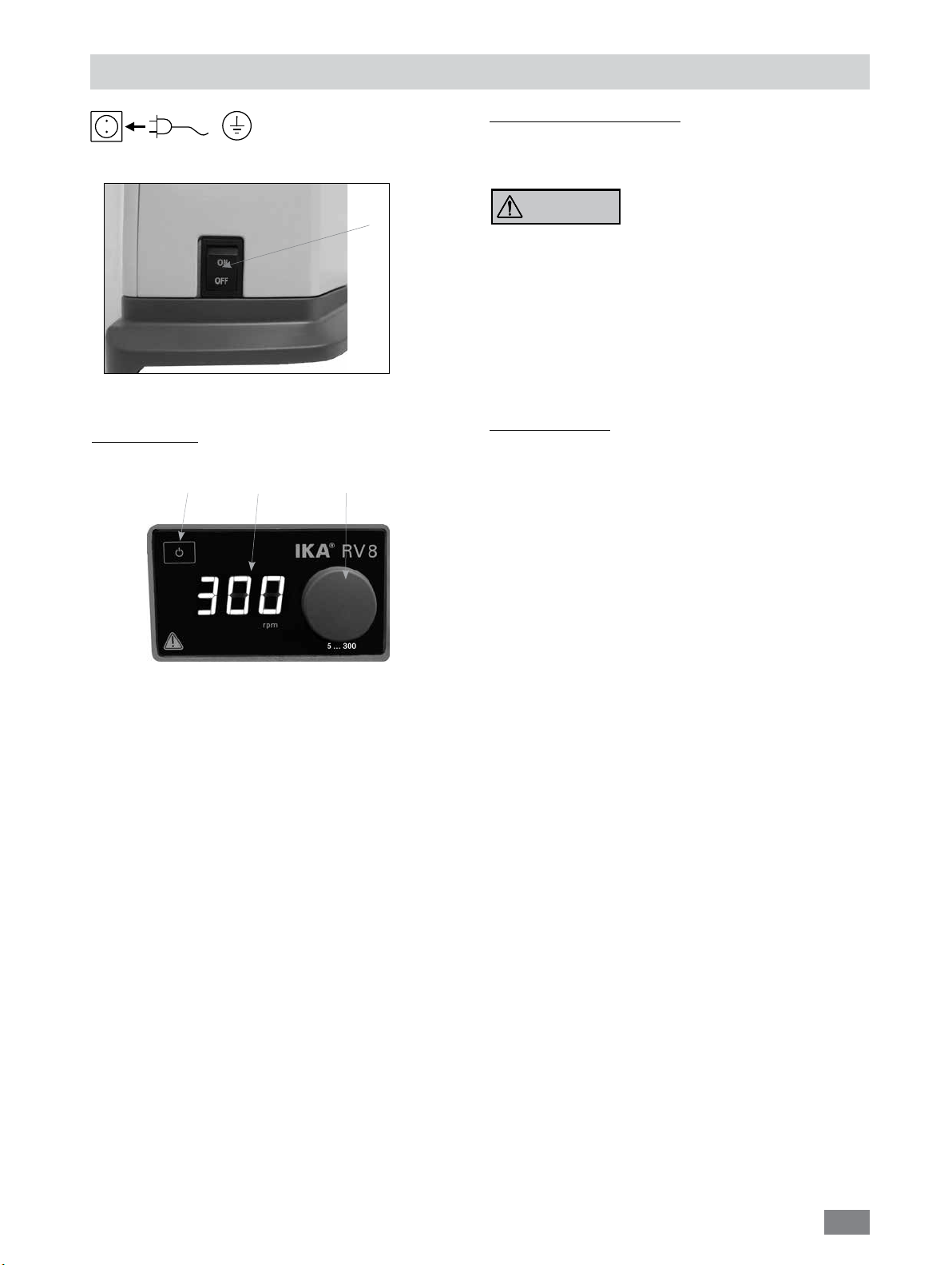
Inbetriebnahme
Das Gerät ist nach Einstecken des
Netzsteckers betriebsbereit.
5
Fig.5
Funktionstasten (Fig.3)
1
• Taste “Power” (1)
Beim Einschalten des Netzschalters (5) schaltet das Gerät auf
den „aktivierten“ Modus.
Drücken Sie die Ein-Taste (1) circa 1 Sekunde lang; der Status
des Geräts wechselt nun vom „aktivierten“ Modus auf den
„Standby“-Modus.
Drücken Sie die Ein-Taste erneut kurz; der Status des Geräts
kehrt damit sofort wieder in den „aktivierten“ Modus zurück.
2
3
Fig.3
Befüllen des Verdampferkolbens:
Sie können vor Anlegen des Vakuums den Verdampferkolben
manuell befüllen. Der Verdampferkolben sollte nicht über die
Hälfte seines Volumens gefüllt werden.
VORSICHT
Befüllen mittels Vakuum: Vor Befüllen des Verdampferkolbens
wird mittels Vakuumsteuerung die Glasapparatur auf Soll-Druck
geregelt.
Befüllen Sie nun über die Nachspeiseleitung den
Verdampferkolben.
- Aufgrund des vorhandenen Unterdrucks wird das Lösemittel
in den Verdampferkolben gesaugt. Dadurch können Sie die
Lösemittelverluste durch Absaugen so gering wie möglich
halten.
Aufstellung Heizbad:
Beachten Sie die Betriebsanleitung des Heizbades HB 10.
- Fahren Sie den Lift in die untere Position und überprüfen Sie
die Heizbadposition zur Lage des Verdampferkolbens. Bei
Verwendung von größeren Verdampferkolben (2 bzw. 3 Liter)
bzw. je nach eingestelltem Winkel des Rotationsantriebs können
Sie das Heizbad nach rechts verschieben.
- Befüllen Sie das Heizbad mit dem Temperiermedium bis der
Verdampferkolben zu 2/3 seines Volumens mit Temperiermedium
umgeben ist.
- Schalten Sie den Rotationsantrieb ein und erhöhen Sie die
Drehzahl langsam.
Hinweis: Vermeiden Sie Wellenbildung.
- Schalten Sie das Heizbad am Hauptschalter ein.
Hinweis: Vermeiden Sie Spannungen am Glas durch
unterschiedliche Verdampferkolben- und Heizbadtemperatur
beim Absenken des Verdampferkolbens in das Heizbad!
Maximal zulässige Zuladung
(Verdampferkolben und Inhalt) beträgt
3 kg.
• Anzeige/Geschwindigkeit (2)
Display (2) zeigt „8.8.8.“
anschließend Softwareversion „X.X“.
Display zeigt „set value“.
Hinweis: Das Gerät ist erst bei Unterbrechung der
Netzspannungsversorgung z.B. durch Ziehen des Netzkabels
stromlos!
• Drehknopf (3)
Zum Start der Rotation drücken Sie den Drehknopf.
Die Anzeige blinkt bis die eingestellte Drehzahl in rpm (revolution
per minute) erreicht ist.
Durch Drehen des Knopfes kann die Drehzahl verändert werden.
Zum Stopp der Rotation drücken Sie erneut den Drehknopf.
Der zuletzt angezeigte Drehzahlwert wird gespeichert.
14
Page 15
Taste Liftposition (4&6) (Fig. 23a und Fig. 23b)
4
Fig.23a
Fig.23b
Zum Verstellen der Liftposition greifen Sie den Griff und drücken
die linke oder rechte Lock-Taste (4).
Die Hand muss am Sensor (6) aufliegen.
Hinweis: Handerkennungs-Sensor (6) nur mit der Hand berühren,
6
nicht drücken!
Der Liftverschluss entriegelt und Sie können den Lift nach oben
und unten bewegen.
Durch Loslassen der Lock-Taste oder Entfernen der Hand verriegelt
der Liftverschluss in der eingestellten Position.
Beim Ver- und Entriegeln ist ein deutliches „Klack“-Geräusch
hörbar.
Montage des Statives RV 8.1 (Zubehör)
Bei ordnungsgemäß montiertem Kühler und festgezogener
Überwurfmutter zum Fixieren des Kühlers am Rotationsantrieb,
wird kein Stativ benötigt.
Das Stativ dient lediglich zur Verdrehsicherung des Kühlers.
WARNUNG
Achtung: Bei unsachgemäß montiertem Stativ RV 8.1 können,
verursacht durch starke Kräfte am Klettband, Spannungen im Glas
entstehen, die zu Beschädigungen des Glaskühlers führen können.
Das Stativ RV 8.1 wird nach der Montage des Kühlers am
Rotationsantrieb befestigt. Beachten Sie, dass der Kühler parallel
zum Liftgehäuse montiert ist.
- Führen Sie den Stativstab in die Bohrung an der Unterseite des
Rotationsantriebes ein,
- Schrauben Sie die Rändelschraube leicht in das Gewinde,
- Verschieben Sie das Stativ, bis die obere Gummimuffe am
Glaskühler anliegt,
- Ziehen Sie die Rändelschraube handfest,
-
Fixieren Sie den Kühler mit dem am Stativ vormontierten Klettband.
Kühler
Stativ RV 8.1
Rotationsantrieb
Fig.24
15
Page 16
Wartung und Reinigung
Das Gerät arbeitet wartungsfrei. Es unterliegt lediglich der natürlichen Alterung der Bauteile und deren statistischer Ausfallrate.
Reinigung
Ziehen Sie zum Reinigen den Netzstecker.
Für die Reinigung des Gerätes ist ausschließlich Wasser mit einem
tensidhaltigen Waschmittelzusatz oder bei stärkerer Verschmutzung Isopropylalkohol zu verwenden.
Ersatzteilbestellung
Bei Ersatzteilbestellungen geben Sie bitte Folgendes an:
- Gerätetyp,
- Fabrikationsnummer des Gerätes, siehe Typenschild,
- Softwareversion,
- Positionsnummer und Bezeichnung des Ersatzteiles,
siehe www.ika.com.
Zubehör (siehe www.ika.com)
Reparaturfall
Bitte senden Sie nur Geräte zur Reparatur ein, die gereinigt und frei von gesundheitsgefährdenden Stoffen
sind.
Fordern Sie hierzu das Formular “Unbedenklichkeitsbescheinigung“ bei IKA
des Formulares auf der IKA
Senden Sie im Reparaturfall das Gerät in der Originalverpackung
zurück. Lagerverpackungen sind für den Rückversand nicht ausreichend. Verwenden Sie zusätzlich eine geeignete Transportverpackung.
®
an, oder verwenden Sie den download Ausdruck
®
Website www.ika.com.
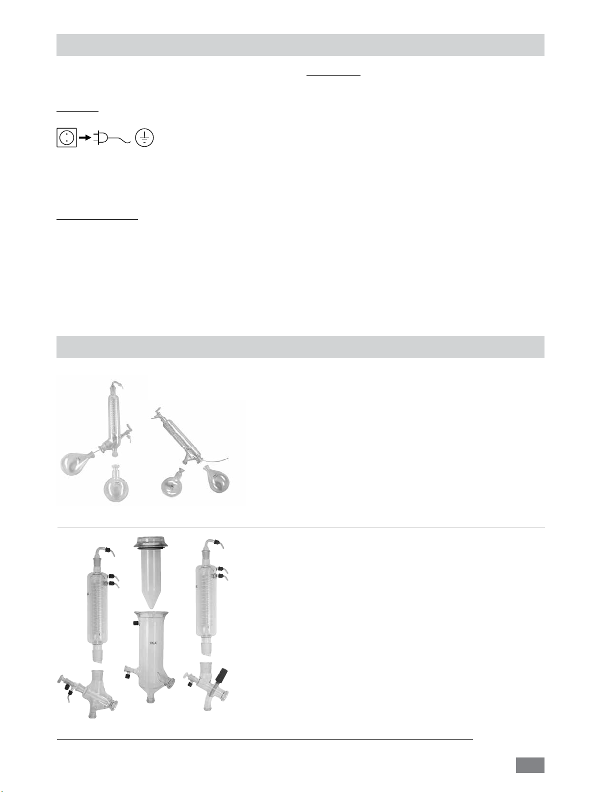
① ②
RV 10.1 NS 29/32 Glassatz vertikal (1)
RV 10.10 NS 29/32 Glassatz vertikal, beschichtet (1)
RV 10.2 NS 29/32 Glassatz diagonal (2)
RV 10.20 NS 29/32 Glassatz diagonal, beschichtet (2)
RV 10.700 NS 29/42 Glassatz vertikal (1)
RV 10.710 NS 29/42 Glassatz vertikal, beschichtet (1)
RV 10.800 NS 29/42 Glassatz diagonal (2)
RV 10.810 NS 29/42 Glassatz diagonal, beschichtet (2)
RV 10.900 NS 24/40 Glassatz vertikal (1)
RV 10.910 NS 24/40 Glassatz vertikal, beschichtet (1)
RV 10.1000 NS 24/40 Glassatz diagonal (2)
RV 10.1010 NS 24/40 Glassatz diagonal, beschichtet (2)
RV 10.3 Vertikal-Intensivkühler mit Verteilerstück(1)
RV 10.30 Vertikal-Intensivkühler mit Verteilerstück, beschichtet (1)
RV 10.4 Trockeneiskühler (2)
RV 10.40 Trockeneiskühler, beschichtet(2)
RV 10.5 Rückflussdestillation mit Vertikalkühler (o.Abb.)
RV 10.50 Rückflussdestillation mit Vertikalkühler, beschichtet (o.Abb.)
RV 10.6 Rückflussdestillation mit Intensivkühler (3)
RV 10.60 Rückflussdestillation mit Intensivkühler, beschichtet (3)
① ② ③
16
Page 17
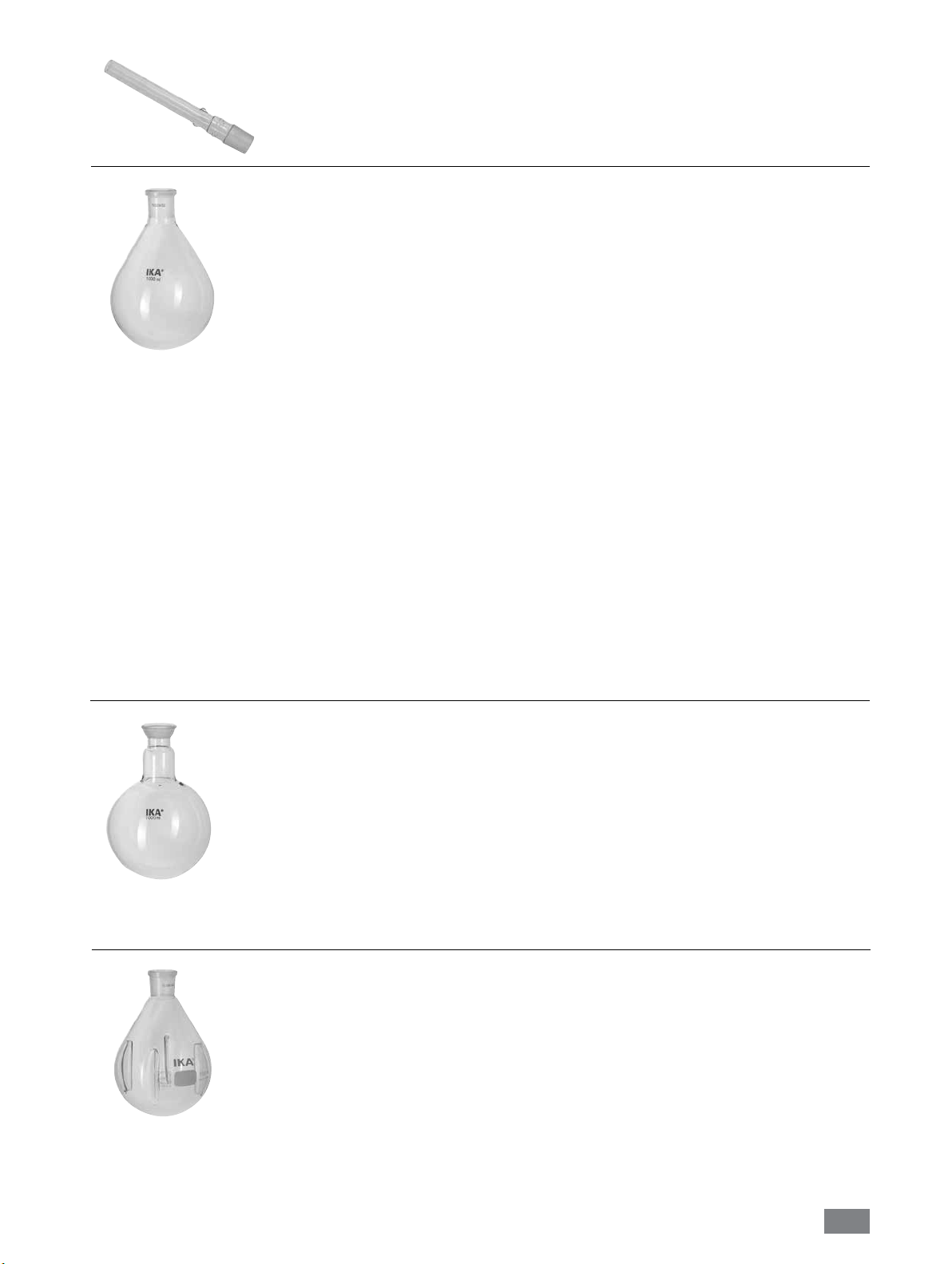
RV 10.70 NS 29/32 Dampfdurchführungsrohr
RV 10.71 NS 24/29 Dampfdurchführungsrohr
RV 10.72 NS 29/42 Dampfdurchführungsrohr
RV 10.73 NS 24/40 Dampfdurchführungsrohr
RV 10.80 NS 29/32 Verdampferkolben 50 ml
RV 10.81 NS 29/32 Verdampferkolben 100 ml
RV 10.82 NS 29/32 Verdampferkolben 250 ml
RV 10.83 NS 29/32 Verdampferkolben 500 ml
RV 10.84 NS 29/32 Verdampferkolben 1000 ml
RV 10.85 NS 29/32 Verdampferkolben 2000 ml
RV 10.86 NS 29/32 Verdampferkolben 3000 ml
RV 10.90 NS 24/32 Verdampferkolben 50 ml
RV 10.91 NS 24/32 Verdampferkolben 100 ml
RV 10.92 NS 24/32 Verdampferkolben 250 ml
RV 10.93 NS 24/32 Verdampferkolben 500 ml
RV 10.94 NS 24/32 Verdampferkolben 1000 ml
RV 10.95 NS 24/32 Verdampferkolben 2000 ml
RV 10.96 NS 24/32 Verdampferkolben 3000 ml
RV 10.97 NS 24/40 Verdampferkolben 1000 ml
RV 10.2001 NS 29/42 Verdampferkolben 50 ml
RV 10.2002 NS 29/42 Verdampferkolben 100 ml
RV 10.2003 NS 29/42 Verdampferkolben 250 ml
RV 10.2004 NS 29/42 Verdampferkolben 500 ml
RV 10.87 NS 29/42 Verdampferkolben 1000 ml
RV 10.2005 NS 29/42 Verdampferkolben 2000 ml
RV 10.2006 NS 29/42 Verdampferkolben 3000 ml
RV 10.2007 NS 24/40 Verdampferkolben 50 ml
RV 10.2008 NS 24/40 Verdampferkolben 100 ml
RV 10.2009 NS 24/40 Verdampferkolben 250 ml
RV 10.2010 NS 24/40 Verdampferkolben 500 ml
RV 10.2011 NS 24/40 Verdampferkolben 1000 ml
RV 10.2012 NS 24/40 Verdampferkolben 2000 ml
RV 10.2013 NS 24/40 Verdampferkolben 3000 ml
RV 10.100 KS 35/20 Auffangkolben 100 ml
RV 10.101 KS 35/20 Auffangkolben 250 ml
RV 10.102 KS 35/20 Auffangkolben 500 ml
RV 10.103 KS 35/20 Auffangkolben 1000 ml
RV 10.104 KS 35/20 Auffangkolben 2000 ml
RV 10.105 KS 35/20 Auffangkolben 3000 ml
RV 10.200 KS 35/20 Auffangkolben, beschichtet 100 ml
RV 10.201 KS 35/20 Auffangkolben, beschichtet 250 ml
RV 10.202 KS 35/20 Auffangkolben, beschichtet 500 ml
RV 10.203 KS 35/20 Auffangkolben, beschichtet 1000 ml
RV 10.204 KS 35/20 Auffangkolben, beschichtet 2000 ml
RV 10.205 KS 35/20 Auffangkolben, beschichtet 3000 ml
RV 10.300 NS 29/32 Pulverkolben 500 ml
RV 10.301 NS 29/32 Pulverkolben 1000 ml
RV 10.302 NS 29/32 Pulverkolben 2000 ml
RV 10.303 NS 24/29 Pulverkolben 500 ml
RV 10.304 NS 24/29 Pulverkolben 1000 ml
RV 10.305 NS 24/29 Pulverkolben 2000 ml
RV 10.2014 NS 29/32 Pulverkolben 500 ml
RV 10.2015 NS 29/32 Pulverkolben 1000 ml
RV 10.2016 NS 29/32 Pulverkolben 2000 ml
RV 10.217 NS 24/40 Pulverkolben 500 ml
RV 10.218 NS 24/40 Pulverkolben 1000 ml
RV 10.219 NS 24/40 Pulverkolben 2000 ml
17
Page 18
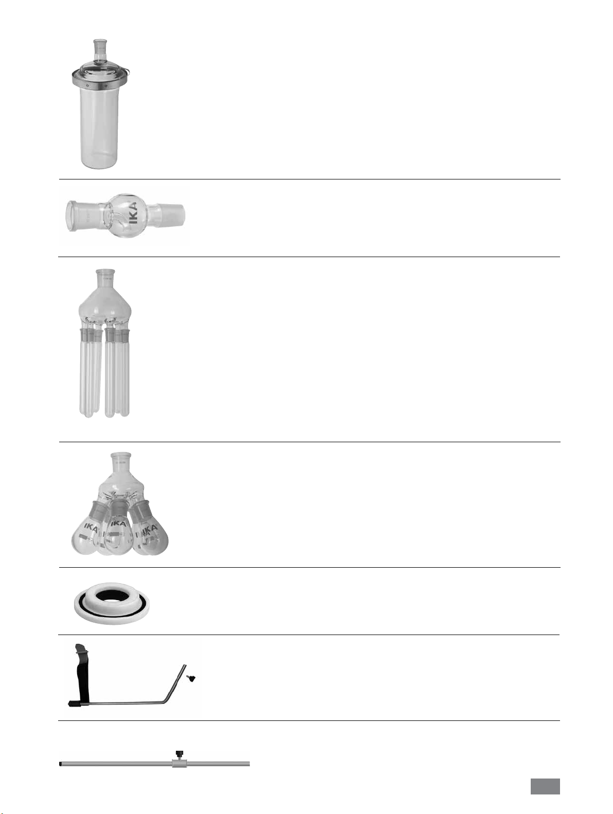
RV 10.400 NS 29/32 Verdampfungszylinder 500 ml
RV 10.401 NS 29/32 Verdampfungszylinder 1500 ml
RV 10.402 NS 24/29 Verdampfungszylinder 500 ml
RV 10.403 NS 24/29 Verdampfungszylinder 1500 ml
RV 10.2020 NS 29/42 Verdampfungszylinder 500 ml
RV 10.2021 NS 29/42 Verdampfungszylinder 1500 ml
RV 10.2022 NS 24/40 Verdampfungszylinder 500 ml
RV 10.2023 NS 24/40 Verdampfungszylinder 1500 ml
RV 10.500 NS 29/32 Schaumbremse
RV 10.501 NS 24/29 Schaumbremse
RV 10.2024 NS 29/42 Schaumbremse
RV 10.2025 NS 24/40 Schaumbremse
RV 10.600 NS 29/32 Destillationsspinne mit 6 Destillierhülsen
RV 10.601 NS 29/32 Destillationsspinne mit 12 Destillierhülsen
RV 10.602 NS 29/32 Destillationsspinne mit 20 Destillierhülsen
RV 10.603 NS 24/29 Destillationsspinne mit 6 Destillierhülsen
RV 10.604 NS 24/29 Destillationsspinne mit 12 Destillierhülsen
RV 10.605 NS 24/29 Destillationsspinne mit 20 Destillierhülsen
RV 10.2026 NS 29/42 Destillationsspinne mit 6 Destillierhülsen
RV 10.2027 NS 29/42 Destillationsspinne mit 12 Destillierhülsen
RV 10.2028 NS 29/42 Destillationsspinne mit 20 Destillierhülsen
RV 10.2029 NS 24/40 Destillationsspinne mit 6 Destillierhülsen
RV 10.2030 NS 24/40 Destillationsspinne mit 12 Destillierhülsen
RV 10.2031 NS 24/40 Destillationsspinne mit 20 Destillierhülsen
RV 10.610 Destillierhülsen 20 ml
RV 10.606 NS 29/32 Destillationsspinne mit 5 Flaschen 50 ml
RV 10.607 NS 29/32 Destillationsspinne mit 5 Flaschen 100 ml
RV 10.608 NS 24/29 Destillationsspinne mit 5 Flaschen 50 ml
RV 10.609 NS 24/29 Destillationsspinne mit 5 Flaschen 100 ml
RV 10.2032 NS 29/42 Destillationsspinne mit 5 Flaschen 50 ml
RV 10.2033 NS 29/42 Destillationsspinne mit 5 Flaschen 100 ml
RV 10.2034 NS 24/40 Destillationsspinne mit 5 Flaschen 50 ml
RV 10.2035 NS 24/40 Destillationsspinne mit 5 Flaschen 100 ml
RV 10.8001 Dichtung
RV 8.1 RV 8.1 Stativ
RV 8.2 RV 8.2 Anschlag
18
Page 19
Fehlercodes
Eine Störung während des Betriebes wird durch eine Fehlermeldung im Display angezeigt.
Nach Anzeigen einer schwerwiegenden Fehlermeldung fährt der Lift in die obere Endlage und die Gerätebedienung ist gesperrt.
Gehen Sie dann wie folgt vor:
- Gerät am Geräteschalter ausschalten,
- Korrekturmaßnahmen treffen,
- Gerät erneut starten.
Fehlercode Grund Ursache Korrektur
E03 Temperatur im Inneren
des Gerätes ist zu hoch
E04 Soll-Drehzahl wird nicht
erreicht
Motor blockiert
E09 Flash-Speicher-Fehler Übertragungsfehler - Schalten Sie das Gerät aus und wieder ein
Lässt sich der Fehler durch die beschriebenen Maßnahmen nicht beseitigen oder wird ein anderer Fehlercode angezeigt:
- wenden Sie sich bitte an die Serviceabteilung,
- senden Sie das Gerät mit einer kurzen Fehlerbeschreibung ein.
Raumtemperatur > 40 °C - Das Gerät ausschalten
- Lassen Sie das Gerät abkühlen
- Prüfen Sie den Standort (siehe Tech.Daten)
Zuladung zu hoch
Kabelbruch
- Reduzieren Sie das Verdampferkolbengewicht
Technische Daten
Betriebsspannungsbereich Vac (100 – 240) ± 10%
Nennspannung Vac 100 – 240
Frequenz Hz 50 / 60
Nennleistung des RV 8 Gerät (ohne Heizbad) W 75
Nennleistung (max.) Schaltadapter W 90
Drehzahl rpm 5 – 300
Drehzahltoleranz Solldrehzahl: < 100 rpm
Solldrehzahl: ≥ 100 rpm
Drehzahlanzeige mm digital
Anzeige Abmessung Sichtbereich (B x H) 37 x 18
Anzeige 7 Segment – Anzeige
Sanftanlauf ja
Lift Handbetrieb
Hub mm 120
Kopfneigung, verstellbar 0° – 45°
Kühlfläche cm
Kühlwasserdurchfluss min. l/h 30
Kühlwasserdurchfluss max. l/h 100
Kühlwasserdruck max. bar 1
Zul. Einschaltdauer % 100
Zul. Umgebungstemperatur °C 5 – 40
Zul. relative Feuchte % 80
Schutzart nach DIN EN 60529 IP 20
Schutzklasse I
Verschmutzungsgrad 2
Gewicht (ohne Glassatz; ohne Heizbad) kg 12.5
Abmessung (B x T x H) mm 595 x 390 x 615
Geräteeinsatz über NN m max. 2000
rpm
%
± 1
± 1
2
1500
Technische Änderung vorbehalten!
19
Page 20

Lösemitteltabelle (Auswahl)
Lösemittel Formel Druck für Siedepunkt bei 40 °C in mbar
(Für HB 10 ca. 60 °C)
Acetic acid C2H4O2 44
Acetone C
Acetonitrile C
N-Amylalcohol C
n-Pentanol C
n-Butanol C
tert. Butanol C
2-Methyl-2-Propanol C
Butylacetate C
Chlorobenzene C
Chloroform CHCI
Cyclohexane C
Dichloromethane CH
Methylenechloride CH
Diethylether C
1,2,-Dichloroethylene (trans) C
Diisopropylether C
Dioxane C
Dimethylformamide (DMF) C
Ethanol C
Ethylacetate C
Ethylmethylketone C
Heptane C
Hexane C
Isopropylalcohol C
Isoamylalcohol C
3-Methyl-1-Butanol C
Methanol CH
Pentane C
n-Propylalcohol C
Pentachloroethane C
1, 1, 2, 2, -Tetrachloroethane C
1, 1, 1, -Trichloroethane C
Tetrachloroethylene C
Tetrachloromethane CCI
Tetrahydrofurane (THF) C
Toluene C
Trichloroethylene C
Water H
Xylene C
O 556
3H6
N 226
2H3
O 11
5H12
O 11
5H10
25
4H10
O 130
4H10
O 130
4H10
39
6H12O2
CI 36
6H5
474
3
235
6H12
atm. press.
2CI2
atm. Press.
2Cl2
O atm. press.
4H10
751
2H2CI2
O 375
6H14
107
4H8O2
NO 11
3H7
O 175
2H6
240
4H8O2
O 243
4H8
120
7H16
335
6H14
O 137
3H8
O 14
5H12
O 14
5H12
O 337
4
atm. press.
5H12
O 67
3H8
HCI5 13
2
35
2H2CI4
300
2H3CI3
53
2CI4
271
4
O 357
4H8
77
7H8
HCI3 183
2
O 72
2
25
8H10
Gewährleistung
Entsprechend den IKA® - Verkaufs- und Lieferbedingungen beträgt
die Gewährleistungszeit 24 Monate. Im Gewährleistungsfall
wenden Sie sich bitte an Ihren Fachhändler. Sie können aber auch
das Gerät unter Beifügung der Lieferrechnung und Nennung der
Reklamationsgründe direkt an unser Werk senden. Frachtkosten
gehen zu Ihren Lasten.
Die Gewährleistung erstreckt sich nicht auf Verschleißteile und
gilt nicht für Fehler, die auf unsachgemäße Handhabung und
unzureichende Pflege und Wartung, entgegen den Anweisungen
in dieser Betriebsanleitung, zurückzuführen sind.
20
Page 21
Source language: German
EN
Contents
Declaration of conformity 21
Explication of warning symbols 21
Safety instructions 21
Correct use 25
Unpacking 25
Useful information 26
Setting up 26
Drive RV 8
Glassware
Hose system
Heating bath
Page
Commissioning 31
Assembling the stand pillar RV 8.1 32
Maintenance and Cleaning 33
Accessories 33
Error Codes 36
Technical data 36
Solvent table (excerpt) 37
Warranty 37
Declaration of conformity
We declare under our sole responsibility that this product corresponds to the regulations 2014/35/EU, 2006/42/EC, 2014/30/EU and
2011/65/EU and conforms with the standards or standardized documents EN 61010-1, EN 61010-2-051; EN 61326-1 and EN 12100.
Explication of warning symbols
General hazard.
This symbol identifies information that is of vital importance for protecting your health and
DANGER
WARNING
CAUTION
DANGER
safety. Disregarding this information may lead to health impairment and injuries.
This symbol identifies information that is of
tioning
of the system.
Disregarding this information may result in damage to the instrument or to system components.
This symbol indicates information which is important for proper use and ensuring that the op-
erations of the instrument
Failure to observe this information may result in inaccurate results.
Danger - Reference to exposure to a hot surface!
Safety instructions
For your protection
The safety lift operates at power failure and
when the device is switched off. It is designed
to raise itself with the glassware attached.
Therefore, please note that the lift without
glass assemblies goes up quickly due to the
reduced weight.
Read the operating instructions completely before
•
starting up and follow the safety instructions.
•
Keep the operating instructions in a place where they can be
accessed by everyone.
vital
importance for the technically correct func-
are performed eciently.
• Ensure that only trained staff work with the appliance.
• Follow the safety instructions, guidelines, occupational health
and safety and accident prevention regulations. When working
under a vacuum in particular!
• Wear your personal protective equipment in accordance with
the hazard category of the medium to be processed. There may
be a risk of:
- splashing liquids,
- body parts, hair, clothing and jewellery getting caught,
- injury as a result of glass breakage.
21
Page 22
DANGER
• Set up the device in a spacious area on an even, stable, clean,
non-slip, dry and fireproof surface.
• Ensure that there is sucient space above the device as the
glass assembly may exceed the height of the device.
• Prior to each use, always check the device, accessories and
especially the glass parts for damage. Do not use damaged
components.
• Ensure that the glass assembly is tension-free! Danger of
cracking as a result of:
- stress due to incorrect assembly,
- external mechanical hazards,
- local temperature peaks.
• Ensure that the stand does not start to move due to vibrations
respectively unbalance.
• Beware of hazards due to:
- flammable materials,
- combustible media with a low boiling temperature,
- glass breakage.
CAUTION
• Do not operate the appliance in explosive atmospheres, with
hazardous substances or under water.
• Only process media that will not react dangerously to the
extra energy produced through processing. This also applies
to any extra energy produced in other ways, e.g. through light
irradiation.
• Tasks with the device must only be performed when operation
is monitored.
• Operation with excess pressure is not permitted (for cooling
water pressure see “Technical Data“).
• Do not cover the ventilation slots of the device in order to
ensure adequate cooling of the drive.
• There may be electrostatic discharges between the medium and
the drive which could pose a direct danger.
• The appliance is not suitable for manual operation (except lift
movement).
• Safe operation is only guaranteed with the accessories described
in the “Accessories” chapter.
• Refer to the operating instructions for the HB 10 heating bath.
• Refer to the operating instructions for the accessories, e.g.
vacuum pump.
• Position the positive pressure outlet of the vacuum pump under
a fume hood.
• Only use the device under an all side-closed exhaust, or a
compa rable protective device.
• Adapt the quantity and the type of distill and to the size of
the distillation equipment. The condenser must work properly.
Monitor the cooling water flow rate at the condenser outlet.
• The glass equipment must always be ventilated when working
under normal pressure (e.g. open outlet at condenser) in order
to prevent a pressure build-up.
• Please note that dangerous concentrations of gases, vapors
or particulate matter can escape through the outlet at the
Inhalation of or contact with media
such as poisonous liquids, gases, spray
mist, vapours, dusts or biological
and microbiological materials can be
hazardous to user.
Only process and heat media that has a
flash point higher than the adjusted safe
temperature limit of the heating bath
that has been set. The safe temperature
limit of the heating bath must always be
set to at least 25 °C lower than the fire
point of the media used.
condenser. Take appropriate action to avoid this risk, for
example, downstream cold traps, gas wash bottles or an
effective extraction system.
• Evacuated glass vessels must not be heated on one side; the
evaporating flask must rotate during the heating phase.
• The glassware is designed for operation under a vacuum of
down to 2 mbar. The equipment must be evacuated prior to
heating (see chapter“Commissioning”). The equipment must
only be aired again after cooling. When carrying out vacuum
distillation, uncondensed vapours must be condensed out or
safely dissipated. If there is a risk that the distillation residue
could disintegrate in the presence of oxygen, only inert gas
must be admitted for stress relief.
CAUTION
DANGER
WARNING
Avoid peroxide formation. Organic
peroxides can accumulate in distillation
and exhaust residues and explode while
decomposing! Keep liquids that tend to
form organic peroxides away from light,
in particular from UV rays and check
them prior to distillation and exhaust for
the presence of peroxides. Any existing
peroxides must be eliminated. Many
organic compounds are prone to the
formation of peroxides, e.g. dekalin,
diethyl ether, dioxane, tetrahydrofuran,
as well as unsaturated hydrocarbons,
such as tetralin, diene, cumene and
aldehydes, ketones and solutions of
these substances.
The heating bath, tempering medium,
evaporation flask and glass assembly
can become hot during operation and
remain so for a long time afterwards!
Let the components cool off before
continuing work with the device.
Avoid delayed boiling! Never heat the
evaporating flask in the heating bath
without switching on the rotary drive!
Sudden foaming or exhaust gases
indicate that flask content is beginning
to decompose. Switch off heating
immediately. Use the lifting mechanism
to lift the evaporation flask out of the
heating bath. Evacuate the danger zone
and warn those in the surrounding area!
22
Page 23

Safety lift
When the device is switched off or the power supply disconnected,
the internal safety lift removes the evaporating flask from the
heating bath.
The safety lift at loss of power is designed for a maximum total
weight (glassware and solvent) of 3.1 kg.
Sample calculation of the maximum load with vertical glassware
and a 1 litre flask:
Condenser + receiving flask + evaporating flask + fittings=
1200 gr + 400 gr + 280 gr + 100 gr = 1980 gr
Maximum loading of solvent = 3100 gr – 1980 gr = 1120 gr
Due to the design, operation of the safety lift cannot be
guaranteed for higher loads!
When using other types of condensers such as dry ice or intensive
condensers, and also when using return distillation distributors
with slip-on condensers, it may be necessary to reduce the load by
the amount of the added weight of the glass apparatus.
Thus, prior to distillation, check whether the lift, laden with the
glassware and distillation material, rises when power is lost.
The safety lift must be checked daily prior to operation!
Attach the maximum total weight of 3.1 kg to the lift. Manually
move the lift to the lowest position and press the “Power“ key on
the front panel or the main switch on the back right side of the
device.
The evaporating flask is lifted out of the heating bath.
®
If the safety lift does not work, please contact the IKA
Service
department.
For the evaporating equipment (evaporating flask plus contents),
the maximum permissible weight is 3.0 kg! Loads greater than this
risk breakage of glass at the steam pipe!
Ensure that the safety lift has been powered down.
When working with large loads, always use low speeds.
Unbalanced loads can result in breakage of the steam pipe!
• A vacuum may be formed inside the glassware in the case of
power outage. The glassware must be vented manually.
Never operate the device when the
CAUTION
evaporation flask is rotating and the lift
is raised. Always lower the evaporation
flask into the heating bath first before
starting the rotation drive. Otherwise
hot tempering medium may be sprayed
out!
•
Set the speed of the drive so no tempering medium is sprayed
out as a result of the evaporation flask rotating in the heating
bath. If necessary reduce the speed.
• Do not touch rotating parts during operation.
•
Imbalance may result in uncontrolled resonance behavior of
the device or assembly. Glass apparatus may be damaged or
destroyed. In the event of unbalance or unusual noises, switch
off the appliance immediately or reduce the speed.
• The appliance does not start up again automatically following a
cut in the power supply.
• The device is only disconnected from the power supply network
if the device power switch is off or the plug is pulled out.
•
The socket for the mains cord must be easily accessible.
For protection of the equipment
•
The voltage stated on the type plate must correspond to the
mains voltage.
• Socket must be earthed (protective ground contact).
•
Removable parts must be refitted to the appliance to prevent
the infiltration of foreign objects, liquids, etc.
•
Protect the appliance and accessories from bumps and impacts.
•
The appliance may only be opened by experts.
23
Page 24
Without glassware!
Lowest position!
Without glassware!
DANGER!
Take care! Fast lift movement without
glassware because of spring inside!
Shut down device only in upper posi-
tion!
With vertical condenser
and steam duct!
Upper position!
Note:
Safe lift movement!
Device can be switched off at any
time!
24
Page 25

Correct use
• Use
Together with the accessories recommended by IKA
device is suitable for:
- quick and gentle distillation of liquids,
- evaporation of solutions and suspensions,
- crystallization, synthesis or cleaning of fine chemicals,
- drying of powder and granulate material,
- recycling of solvents.
Mode of operation: Tabletop device
®
• Range of use
- Laboratories - Schools
, the
- Pharmacies - Universities
The safety of the user cannot be guaranteed if: the appliance is
operated with accessories that are not supplied or recommended
by the manufacturer, the appliance is operated improperly
according to the manufacturer’s specifications.
Unpacking
• Unpacking
- Please unpack the device carefully
- In the case of any damage a report must be sent immediately (post, rail or forwarder)
• Contents of package
DIN911 SW5
Holding bracket
Condensate flask
Screwed Plug D
Screwed -Joint Cap
Tube clip D=9mm
Operating instructions
Base
Drive RV 8
Heating bath HB 10
Vertical glassware RV 10.1
Vertical glassware RV 10.10 coated
Serrated washer M6
Cylindrical M6x25
Ring spanner
Desktop switching
RV 10.8001 Seal
Foot
Right-angle T20
Package 1 / RV 8 V 1 1 1 4 4 1 1 1 1 1 1 1 1 1 2 2 1 1 1 2
Package 2 / RV 8 VC 1 1 1 4 4 1 1 1 1 1 1 1 1 1 2 2 1 1 1 2
Package 3 / RV 8 flex 1 1 4 4 1 1 1 1 1 1 1 1 1 2 2 1 1 1 2
Contents of package
RV 8
HEXAGON
Vapour tube
Power cable
Fig. 6
25
Page 26
Useful information
Distillation is a thermal separating process for liquid compounds
based on substance-specific, pressure-dependent boiling points
through evaporation and subsequent condensation.
The boiling point temperature decreases with decreasing external
pressure which means that work is usually done under reduced pressure. In this way the heating bath can be maintained at a constant
temperature (e.g. 60 °C). Using the vacuum, the boiling point is set
with a steam temperature of approx. 40 °C. The cooling water for
the condensation condenser should not be warmer than 20 °C (6040-20 rule).
A chemical resistant membrane pump with a vacuum controller
should be used to create the vacuum. The pump is protected from
solvent residue by the addition of a Woulff bottle and/or a vacuum
separator.
Working with a jet pump to create a vacuum can only be recom
mended to a limited extent as the solvents may contaminate the environment when using these systems.
Speed, temperature, flask size and system pressure all affect the
evaporator air capacity.
The optimum capacity of the flow-through condenser is approx.
60%.
This corresponds to condensation on approx. 2/3 of the cooling
coil. With larger capacities there is the risk that the uncondensed
solvent vapor will be extracted.
-
CAUTION
When using other types of condensers such as dry ice or intensive
condensers as well as when using return distillation distributors
with slip-on condensers, it may be necessary to reduce the mass
of the media to compensate for the mass of this additional glassware. Thus, prior to distillation, check whether the lift goes up
without power when laden with the glass and distillation material.
The device is designed for operation with a cooling water supply
system (e.g. laboratory thermostat), but can also be run off a water supply line. Please refer to the Technical Data for information
on cooling water pressure, temperature constancy, and flow rate.
The device is equipped with a Lift safety
unit.
If the power cuts out, the evaporation
flask is automatically lifted out of the
heating bath by an integrated gas spring.
“CAUTION! The safety lift must be
checked daily before use. See safety
notes / safety lift ! “
The glass apparatus can be evacuated
after power outage!
Drive RV 8
1.) Mount the base to the lift. (Fig. 7)
F
G
Apply
•
to mount
(Fig. 7)
Cylindrical M6x25
base
(H) with Lift Unit (I) after you unpack the package.
(F) (4x) and
Serrated washer M6
H
I
Fig. 7
Setting up
2.) Remove transportation lock (Fig. 8)
J
(G) (4x)
CAUTION
Hold the lift with your
•
hand on the height
position and remove the
thumb screw (J) by turning
counterclockwise on the
back of the appliance.
Take care! DANGER!
Once the transportation
lock has been removed, the
lift moves fast to its upper
end position. The distance is
approx.120 mm.
Fig. 8
26
Page 27
3.) Fix the Desktop switching. (Fig. 9)
K
N
M
L
Fig. 9
• Attach the switching adapter (K) on the rear side. Secure it with
the Velcro, by contracting both tabs on the switching adapter.
The Velcro must not be below the switching adapter.
•
Connect the Low-voltage connector (M) to the connection
socket (N). (Fig. 9)
• Plug the power cord (L) in the switching adapter and connect it
to the power source.
• Observe the valid supply voltage.
6.) Adjust the angle of the rotation head. (Fig. 12)
•
Remove the clamping device for the angle setting of the
rotation drive on the right side of the lift by rotating the knob
counterclockwise.
Fig.12
7.) Set the drive at an angle of approx. 30°. (Fig. 13)
4.) Fix the Holding bracket (Fig.10)
Fig.10
5.) Insert the bottle and attach the supplied hose
connectors to the bottle.
(Fig. 11)
30°
Fig.13
Then, secure the rotary drive against rotation by tightening the
•
adjustable knob clockwise.
Fig.11
27
Page 28

Glassware
NOTE: Please read the operating instructions of the glassware for
the safe handling of laboratory glassware !
• There is a locking knob (P) for locking or unlocking the locking
device (O).
If a red mark (Q) is shown, the locking device is unlocked,
otherwise it is locked.
To lock or unlock the locking device (O), push the locking knob
(P) to the end position.
Q
O
• Pushing the lock knob (P) to the end position, the red mark (Q)
should be covered and invisible.
• The vapour tube is not allowed to be pulled out!
• Check the correct axial locking device on the vapour tube.
• Keep the red mark (Q) invisible.
Fit & unfit the evaporation flask / push off mechanism
O
S
R
P
Fig.14a
•
Open the locking device (O) on the drive head by turning it 60°
counterclockwise. Then you can see a red mark (Q) .
See indication:
“CLOSE“
Fig.14b
Feed the vapour tube (R) in until it stops.
•
• Then, lock the locking device (O) by turning it clockwise by 60°.
Fig.15a
O
S
T
Fig.15b
Turn clockwise () for tight-fitting
Turn counterclockwise () for loosen tight-fitting
Mount the evaporation flask:
- Place the evaporation flask on the Vapour tube (R). (Fig.15a)
- Turn the plastic nut (S) with the clip (T) counterclockwise until
the clip can be put on the flange. (Fig. 15b)
- Now turn the plastic nut clockwise until the clamp is hard up
against the flange. When doing so, hold the locking device (O)
on the steam pipe.
R
Fig.14c
Remove the evaporation flask:
- Hold the locking device (O) and loosen the plastic nut by turning
it counterclockwise. This releases a tightly clamped evaporating
flask.
- Hold the evaporating flask at the flange and open the jaws of
the clamp.
- Remove the evaporating flask.
- Check that the locking of vapour tube is still closed!
28
Page 29
• Place the RV 10.8001 condenser seal (U) in the condenser
receptacle and fit the glassware to the device according to the
assembly instructions. (Fig. 16, 17 and 18)
U
Fig.16
Fig.18
Mount the condenser
• Place the cap nut into the condenser, and then put the spring
ring to the flange of the condenser (V).
• Place the condenser on the rotary drive (W) and tighten the cap
nut by hand. (Fig.17)
V
W
Mounting the washer
Drainage
washer
Note: Pay attention to the
correct position of the washer.
Removing the condenser
•
Use the ring spanner provided to loosen union nuts that are
tightly fitted.
• Loosen the union nut by turning anticlockwise.
Fig.19a
Fig.19b
Fig.17
• Fix the receiving flask and hose connectors as shown. See also
operating manual of glassware. (Fig.18)
Description of special condensers
(see products/accessories at www.ika.com)
• RV 10.3 Vertical-intensive condenser with manifold
This vertical-intensive condenser features a double jacket design
for particularly efficient condensation.
Also available with coating (RV 10.30)
• RV 10.4 Dry ice condenser
Dry ice condenser for distilling low-boiling solvents. Cooling
by dry ice, no cooling water required. Maximum condensation
thanks to low temperatures.
Also available with coating (RV 10.40)
29
Page 30

• RV 10.5 Vertical-condenser with manifold and cut-off valve
for reflux distillation
Also available with coating (RV 10.50)
• RV 10.6 Vertical-intensive condenser with manifold and
cut-off valve for reflux distillation
This vertical-intensive action condenser features a double jacket
design for particularly efficient reflux distillation.
Also available with coating (RV 10.60)
Hose system
•
Connect the water hoses (H2O) to the condenser according to
the counter-flow principle. (Fig. 20)
•
Install the vacuum connections to the condenser, Woulff bottle,
vacuum controller with valve and vacuum pump.
• Always connect the vacuum hose (vac) to the condenser at the
highest point to minimize solvent losses during suctioning.
•
Use standard laboratory vacuum hoses with an inside diameter
of 8 mm and a wall thickness of 5 mm (see accessories).
Z
Fig. 21a
Fig. 20
Heating bath HB 10
Refer to the chapter entitled
CAUTION
• Assemble the foot of the heating bath HB 10
For operation of the HB 10 heating bath in combination with the
RV 8, the foot plate supplied must be fitted to the heating bath.
Caution: It is not permitted to use HB 10 heating bath fitted
with a foot plate in combination with any other type of rotary
evaporator.
“Commissioning“ in the heating bath
instruction manual
!
Fig. 21b
Unscrew the screw (Z) fully out of the foot. (Fig. 21a)
Press the foot with the pin and the O-rings on it into the hole in
the heating bath base plate as far as the stop.
Tighten the screw (Z) by hand. (Fig.21b)
• Place the heating bath on the stand of the rotation drive and
push it into the left position. (Fig. 22)
Fig. 22
30
Page 31

Commissioning
The unit is ready for service when
the mains plug has been plugged
in.
5
Fig.5
Function keys (Fig.3)
1
• “Power” key (1)
When the power switch (5) is switched on, the device will be in
“activated” mode.
Touch the “Power” key (1) for about 1 second, the status of the
device will be changed from “activated” mode to “stand-by”
mode.
Touch the “Power” key again shortly, the status of the device
will be changed back to ”activated” mode immediately.
2
3
Fig.3
Filling the evaporation flask:
You can fill the evaporation flask manually prior to creating the
vacuum. The evaporation flask should not be filled more than half
its volume.
CAUTION
Filling medium by vacuum: prior to filling the evaporation flask, a
vacuum controller is used to regulate the glass apparatus to the
target pressure.
Now fill the evaporation flask using the backfeed line.
-
- Due to the vacuum present, the solvent is suctioned into the
evaporation flask. This enables you to keep solvent loss due to
suctioning to a minimum.
Setting up the heating bath:
Also refer to the operating instructions for the HB 10 heating
bath!
Move the lift to the bottom position and check the position
of the heating bath in relation to the evaporation flask. When
using larger evaporation flasks (2 or 3 liters) or depending on
the angle of the rotation drive, you can move the heating bath
to the right.
-
Fill the heating bath with the tempering medium until the
evaporation flask is surrounded by tempering medium to 2/3
of its volume.
- Switch on the rotation drive and slowly increase the speed.
Note: Avoid creating waves.
- Switch on the heating bath using the main on/off switch.
Note: Avoid stress on the glass due to different evaporation flask
and heating bath temperatures when lowering the evaporation
flask into the heating bath!
The maximum allowed load (evaporation
flask and contents) is 3 kg.
• Display window/speed (2)
Display (2) shows “8.8.8.“
then Softwareversion “X.X“.
Display shows “set value“.
Note: The device is not deenergized until the mains power
supply has been interrupted, for instance by unplugging the
power cable.
• Rotating knob (3)
To start the rotation, press the rotary knob.
The indicator flashes until the set speed in rpm (revolution per
minute) is reached.
By turning the rotary knob, the speed can be changed.
To stop the rotation, press the rotary knob again.
The last displayed speed value is stored.
31
Page 32

Lift position key
(4&6) (Fig. 23a and Fig. 23b)
To adjust the lift position, grasp the handle and press the left or
right lock button (4).
The hand must rest on the sensor (6).
Note: Hand detection sensor (6), only to be touched by hand,
6
do not press!
The lift lock is unlocked and you can move the lift up and down.
Release the lock button or remove the hand from the lift, the lift
is locked in the adjusted position.
When locking and unlocking, a clear “click“ sound is heard.
4
Fig.23a
Fig.23b
Assembling the stand pillar RV 8.1 (Accessories)
No stand is required if the condenser has been properly fitted
and secured by tightening the condenser union nut on the rotary
drive.
The purpose of the stand is solely to prevent the condenser
twisting.
WARNING
Caution: If the RV 8.1 stand is fitted incorrectly, the strong forces
at the Velcro strap can cause stresses within the glass, which in
turn can cause damage to the glass condenser.
Stand pillar RV 8.1
After the condenser has been fitted, the RV 8.1 stand is attached
to the rotary drive. Make sure that the condenser is installed
parallel to the lift body.
- Guide the stand rod through the hole on the underside of the
rotary drive,
- Screw the knurled screw into the tapped hole but do not tighten
it,
- Move the stand until the upper rubber sleeve rests against the
glass condenser,
- Tighten the knurled screw finger-tight,
- Secure the condenser to the stand using the pre-fitted Velcro
strap.
Condenser
Rotary drive
Fig.24
32
Page 33

Maintenance and Cleaning
The instrument is maintenance-free. It is only subject to the natural wear and tear of components and their statistical failure rate.
Cleaning
Disconnect main plug prior to cleaning!
To clean the device use only water with a detergent that contains
tenside, or use isopropyl alcohol for stubborn soiling.
Spare parts order
When ordering spare parts, please give:
- Machine type,
- Serial number, see type plate,
- Software version,
-
Item
number
see www.ika.com.
and designation of the spare part
,
Accessories (see www.ika.com)
Repair
Please send instrument in for repair only after it has been
cleaned and is free from any materials which may consti
tute a health hazard.
For this you should request the “Decontamination Clearance
Certificate” from IKA®, or use the download printout of it from
®
the IKA
Return the instrument in its original packaging. Storage packag
ing is not sucient. Also, please use suitable shipping package
materials.
website www.ika.com.
-
-
① ②
RV 10.1 NS 29/32 Vertical glassware (1)
RV 10.10 NS 29/32 Vertical glassware, coated (1)
RV 10.2 NS 29/32 Diagonal glassware (2)
RV 10.20 NS 29/32 Diagonal glassware, coated (2)
RV 10.700 NS 29/42 Vertical glassware (1)
RV 10.710 NS 29/42 Vertical glassware, coated (1)
RV 10.800 NS 29/42 Diagonal glassware (2)
RV 10.810 NS 29/42 Diagonal glassware, coated (2)
RV 10.900 NS 24/40 Vertical glassware (1)
RV 10.910 NS 24/40 Vertical glassware, coated (1)
RV 10.1000 NS 24/40 Diagonal glassware (2)
RV 10.1010 NS 24/40 Diagonal glassware, coated (2)
RV 10.3 Vertical-intensive condenser with manifold (1)
RV 10.30 Vertical-intensive condenser with manifold, coated (1)
RV 10.4 Dry ice condenser (2)
RV 10.40 Dry ice condenser , coated (2)
RV 10.5 Vertical-condenser with manifold and cut-off valve
for reflux distillation (no picture)
RV 10.50 Vertical-condenser with manifold and cut-off valve
for reflux distillation, coated (no picture)
RV 10.6 Vertical-intensive condenser with manifold and cut-off valve
for reflux distillation (3)
RV 10.60 Vertical-intensive condenser with manifold and cut-off valve
for reflux distillation, coated (3)
① ② ③
33
Page 34

RV 10.70 NS 29/32 Vapour tube
RV 10.71 NS 24/29 Vapour tube
RV 10.72 NS 29/42 Vapour tube
RV 10.73 NS 24/40 Vapour tube
RV 10.80 NS 29/32 Evaporation flask 50 ml
RV 10.81 NS 29/32 Evaporation flask 100 ml
RV 10.82 NS 29/32 Evaporation flask 250 ml
RV 10.83 NS 29/32 Evaporation flask 500 ml
RV 10.84 NS 29/32 Evaporation flask 1000 ml
RV 10.85 NS 29/32 Evaporation flask 2000 ml
RV 10.86 NS 29/32 Evaporation flask 3000 ml
RV 10.90 NS 24/32 Evaporation flask 50 ml
RV 10.91 NS 24/32 Evaporation flask 100 ml
RV 10.92 NS 24/32 Evaporation flask 250 ml
RV 10.93 NS 24/32 Evaporation flask 500 ml
RV 10.94 NS 24/32 Evaporation flask 1000 ml
RV 10.95 NS 24/32 Evaporation flask 2000 ml
RV 10.96 NS 24/32 Evaporation flask 3000 ml
RV 10.97 NS 24/40 Evaporation flask 1000 ml
RV 10.2001 NS 29/42 Evaporation flask 50 ml
RV 10.2002 NS 29/42 Evaporation flask 100 ml
RV 10.2003 NS 29/42 Evaporation flask 250 ml
RV 10.2004 NS 29/42 Evaporation flask 500 ml
RV 10.87 NS 29/42 Evaporation flask 1000 ml
RV 10.2005 NS 29/42 Evaporation flask 2000 ml
RV 10.2006 NS 29/42 Evaporation flask 3000 ml
RV 10.2007 NS 24/40 Evaporation flask 50 ml
RV 10.2008 NS 24/40 Evaporation flask 100 ml
RV 10.2009 NS 24/40 Evaporation flask 250 ml
RV 10.2010 NS 24/40 Evaporation flask 500 ml
RV 10.2011 NS 24/40 Evaporation flask 1000 ml
RV 10.2012 NS 24/40 Evaporation flask 2000 ml
RV 10.2013 NS 24/40 Evaporation flask 3000 ml
RV 10.100 KS 35/20 Receiving flask 100 ml
RV 10.101 KS 35/20 Receiving flask 250 ml
RV 10.102 KS 35/20 Receiving flask 500 ml
RV 10.103 KS 35/20 Receiving flask 1000 ml
RV 10.104 KS 35/20 Receiving flask 2000 ml
RV 10.105 KS 35/20 Receiving flask 3000 ml
RV 10.200 KS 35/20 Receiving flask, coated 100 ml
RV 10.201 KS 35/20 Receiving flask, coated 250 ml
RV 10.202 KS 35/20 Receiving flask, coated 500 ml
RV 10.203 KS 35/20 Receiving flask, coated 1000 ml
RV 10.204 KS 35/20 Receiving flask, coated 2000 ml
RV 10.205 KS 35/20 Receiving flask, coated 3000 ml
RV 10.300 NS 29/32 Powder flask 500 ml
RV 10.301 NS 29/32 Powder flask 1000 ml
RV 10.302 NS 29/32 Powder flask 2000 ml
RV 10.303 NS 24/29 Powder flask 500 ml
RV 10.304 NS 24/29 Powder flask 1000 ml
RV 10.305 NS 24/29 Powder flask 2000 ml
RV 10.2014 NS 29/32 Powder flask 500 ml
RV 10.2015 NS 29/32 Powder flask 1000 ml
RV 10.2016 NS 29/32 Powder flask 2000 ml
RV 10.217 NS 24/40 Powder flask 500 ml
RV 10.218 NS 24/40 Powder flask 1000 ml
RV 10.219 NS 24/40 Powder flask 2000 ml
34
Page 35

RV 10.400 NS 29/32 Evaporation cylinder 500 ml
RV 10.401 NS 29/32 Evaporation cylinder 1500 ml
RV 10.402 NS 24/29 Evaporation cylinder 500 ml
RV 10.403 NS 24/29 Evaporation cylinder 1500 ml
RV 10.2020 NS 29/42 Evaporation cylinder 500 ml
RV 10.2021 NS 29/42 Evaporation cylinder 1500 ml
RV 10.2022 NS 24/40 Evaporation cylinder 500 ml
RV 10.2023 NS 24/40 Evaporation cylinder 1500 ml
RV 10.500 NS 29/32 Foam brake
RV 10.501 NS 24/29 Foam brake
RV 10.2024 NS 29/42 Foam brake
RV 10.2025 NS 24/40 Foam brake
RV 10.600 NS 29/32 Distillation spider with 6 distilling sleeves
RV 10.601 NS 29/32 Distillation spider with 12 distilling sleeves
RV 10.602 NS 29/32 Distillation spider with 20 distilling sleeves
RV 10.603 NS 24/29 Distillation spider with 6 distilling sleeves
RV 10.604 NS 24/29 Distillation spider with 12 distilling sleeves
RV 10.605 NS 24/29 Distillation spider with 20 distilling sleeves
RV 10.2026 NS 29/42 Distillation spider with 6 distilling sleeves
RV 10.2027 NS 29/42 Distillation spider with 12 distilling sleeves
RV 10.2028 NS 29/42 Distillation spider with 20 distilling sleeves
RV 10.2029 NS 24/40 Distillation spider with 6 distilling sleeves
RV 10.2030 NS 24/40 Distillation spider with 12 distilling sleeves
RV 10.2031 NS 24/40 Distillation spider with 20 distilling sleeves
RV 10.610 Distilling sleeve 20 ml
RV 10.606 NS 29/32 Distillation spider with 5 flasks 50 ml
RV 10.607 NS 29/32 Distillation spider with 5 flasks 100 ml
RV 10.608 NS 24/29 Distillation spider with 5 flasks 50 ml
RV 10.609 NS 24/29 Distillation spider with 5 flasks 100 ml
RV 10.2032 NS 29/42 Distillation spider with 5 flasks 50 ml
RV 10.2033 NS 29/42 Distillation spider with 5 flasks 100 ml
RV 10.2034 NS 24/40 Distillation spider with 5 flasks 50 ml
RV 10.2035 NS 24/40 Distillation spider with 5 flasks 100 ml
RV 10.8001 Seal
RV 8.1 RV 8.1 Stand pillar
RV 8.2 RV 8.2 Stopper
35
Page 36

Error Codes
Any malfunctions during operation will be identified by an error message on the display.
Once a serious error message has been displayed, the lift moves to the top end position and the device can no longer be operated.
Proceed as follows in such cases:
- switch off device using the main switch,
- carry out corrective measures,
- restart device.
Error code Cause Effect Correction
E03 Temperature inside the device
is too high
E04 Target speed is not reached
Motor blocked
E09 Flash memory storage error Transmission error - Turn the unit off and on again
If the actions described fail to resolve the fault or another error code is displayed, then take one of the following steps:
- contact the service department,
- send the device for repair, including a short description of the fault.
Room temperature > 40 °C - Switch off the device
- Let the device cool down
- Check the location (see Technical data)
Load too large
Cable break
- Reduce the volume in the evaporator
Technical data
Operating voltage range Vac (100 – 240) ± 10%
Rated voltage Vac 100 – 240
Frequency Hz 50 / 60
Rated power of RV 8 device(without heating bath) W 75
Rated power (max.) of switching adaptor W 90
Speed rpm 5 – 300
Speed tolerance Set speed: < 100 rpm
Set speed: ≥ 100 rpm
Speed display mm digital
Dimensions of visible display area (W x H) 37 x 18
Display 7 segments display
Smooth start yes
Lift manual
Stroke mm 120
Head angle adjustable 0° – 45°
Cooling surface cm
Cooling water flow rate min. l/h 30
Cooling water flow rate max. l/h 100
Cooling water pressure max. bar 1
Perm. On-time % 100
Perm. ambient temperature °C 5 – 40
Perm. relative humidity % 80
Protection acc. to DIN EN 60529 IP 20
Protection class I
Contamination level 2
Weight (no glassware; no heating bath) kg 12.5
Dimensions (W x D x H) mm 595 x 390 x 615
Operation at a terrestrial altitude m max. 2000
rpm
%
± 1
± 1
2
1500
Subject to technical changes!
36
Page 37

Solvent table (excerpt)
Solvent Formula Pressure for boiling point 40 °C in mbar
(For HB 10 approx. 60 °C)
Acetic acid C
Acetone C
Acetonitrile C
N-Amylalcohol C
n-Pentanol C
n-Butanol C
tert. Butanol C
2-Methyl-2-Propanol C
Butylacetate C
Chlorobenzene C
Chloroform CHCI
Cyclohexane C
Dichloromethane CH
Methylenechloride CH
Diethylether C
1,2,-Dichloroethylene (trans) C
Diisopropylether C
Dioxane C
Dimethylformamide (DMF) C
Ethanol C
Ethylacetate C
Ethylmethylketone C
Heptane C
Hexane C
Isopropylalcohol C
Isoamylalcohol C
3-Methyl-1-Butanol C
Methanol CH
Pentane C
n-Propylalcohol C
Pentachloroethane C
1, 1, 2, 2, -Tetrachloroethane C
1, 1, 1, -Trichloroethane C
Tetrachloroethylene C
Tetrachloromethane CCI
Tetrahydrofurane (THF) C
Toluene C
Trichloroethylene C
Water H
Xylene C
44
2H4O2
O 556
3H6
N 226
2H3
O 11
5H12
O 11
5H10
25
4H10
O 130
4H10
O 130
4H10
39
6H12O2
CI 36
6H5
474
3
235
6H12
atm. press.
2CI2
atm. Press.
2Cl2
O atm. press.
4H10
751
2H2CI2
O 375
6H14
107
4H8O2
NO 11
3H7
O 175
2H6
240
4H8O2
O 243
4H8
120
7H16
335
6H14
O 137
3H8
O 14
5H12
O 14
5H12
O 337
4
atm. press.
5H12
O 67
3H8
HCI5 13
2
35
2H2CI4
300
2H3CI3
53
2CI4
271
4
O 357
4H8
77
7H8
HCI3 183
2
O 72
2
25
8H10
Warranty
In accordance with IKA® warranty conditions, the warranty
period is 24 months. For claims under the warranty please contact
your local dealer. You may also send the machine directly to our
factory, enclosing the delivery invoice and giving reasons for the
claim. You will be liable for freight costs.
The warranty does not cover worn out parts, nor does it apply
to faults resulting from improper use, insufficient care or
maintenance not carried out in accordance with the instructions
in this operating manual.
37
Page 38

Langue d‘origine: allemand
FR
Sommaire
Déclaration de conformité 38
Explication des symboles 38
Conseils de sécurité 38
Utilisation conforme 42
Déballage 42
Conseils pratiques 43
Installation 43
Entraînement RV 8
Verrerie
Gainage
Bain chauffant
Seite
Mise en service 48
Montage du tenez pilier RV 8.1 49
Entretien et nettoyage 50
Accessoires 50
Messages d‘erreurs 53
Caractéristiques techniques 53
Tableau des solvants (sélection) 54
Garantie 54
Déclaration de conformité
Nous déclarons sous notre propre responsabilité que ce produit est conforme aux réglementations 2014/35/UE, 2006/42/CE, 2014/30/
UE et 2011/65/UE et en conformité avec les normes ou documents normalisés suivant EN 61010-1, EN 61010-2-051; EN 61326-1 et
EN 12100.
Explication des symboles
Remarque générale sur un danger.
Le présent symbole signale des informations cruciales pour la sécurité de votre santé. Un non-
DANGER
AVERTISSEMENT
CAUTION
DANGER
respect peut provoquer des problèmes de santé ou des blessures.
Le présent symbole signale des informations importantes pour le bon fonctionnement tech-
nique de l‘appareil. Le non-respect de ces indications peut endommager l‘appareil.
Le présent symbole signale des informations importantes pour le bon déroulement des
fonctions de l‘appareil et pour la manipulation de l‘appareil.
Le non-respect des ces indications peut avoir pour conséquence des résultats de mesure imprécis.
Danger - Référence à l‘exposition à une surface chaude !
Conseils de sécurité
Pour votre protection
Le dispositif de levage de sécurité est conçu
pour lever le dispositif avec la verrerie
montée en cas de panne de courant et d’arrêt
de l’appareil. C’est pourquoi il faut faire
attention au dispositif sans structure en verre
qui monte rapidement en raison du poids
réduit.
•
Lisez intégralement la notice d’utilisation avant la mise
en service et respectez les consignes de sécurité.
•
Laissez la notice à portée de tous.
• Attention, seul le personnel formé est autorisé à utiliser l’appareil.
• Respectez les consignes de sécurité, les directives, ainsi que les
prescriptions pour la prévention des accidents du travail. En
particulier lors des travaux sous vide!
• Portez votre équipement de protection personnel selon la classe
de danger du milieu à traiter. Sinon, vous vous exposez à des
dangers:
- aspersion de liquides,
- happement de parties du corps, cheveux, habits et bijoux,
- bris de verre.
38
Page 39

DANGER
• Placez l’appareil en aire spacieuse sur une surface plane, stable,
propre, non glisssante, sèche et ininflammable.
• Prévoyez un espace en hauteur suffisant, car la structure en
verre peut dépasser la hauteur de l'appareil.
• Avant chaque utilisation, contrôlez l'état de l'appareil, des
accessoires et en particulier des pièces en verre. N'utilisez pas
les pièces endommagées.
• Veillez à obtenir une structure en verre libre de contrainte !
Risque d'éclatement par:
- les tensions dues à un assemblage défectueux,
- les influences mécaniques externes,
- les pics de températures sur place.
• Veiller à ce que le statif ne commence pas à se dérégler en cas
de décentrage ou vibrations.
• Vous vous exposez à des dangers par:
- les matériaux inflammables,
- les milieux combustibles à faible température d‘ébullition,
- bris de verre.
CAUTION
• N‘utilisez pas l‘appareil dans les atmosphères explosives, avec
des matières dangereuses et sous l‘eau.
• Ne traitez que des milieux pour lesquels l‘apport d‘énergie
pendant l‘opération ne pose pas problème. Cela vaut aussi pour
lesautres apports d‘énergie, comme la radiation lumineuse par
ex.
• Travaillez seulement en mode surveillé avec l’appareil.
• Le fonctionnement avec une surpression est interdit (pression
de l‘eau de refroidissement, voir „Caractéristiques techniques“).
• Ne pas couvrir les fentes d‘aération servant au refroidissement
de l‘entraînement.
• Il peut se produire des décharges électrostatiques entre le milieu
et l‘appareil qui constituent un risque direct.
• L‘appareil n‘est pas adapté à un fonctionnement manuel(sauf le
mouvement de levage).
• La sécurité de l‘appareil n‘est assurée qu‘avec les accessoires
décrits dans le chapitre „Accessoires“.
• Suivez le mode d‘emploi du bain chauffant du HB 10.
• Respectez le mode d‘emploi des accessoires, par ex. de la
pompe à vide.
• Placez la sortie côté pression de la pompe à vide dans la hotte
de laboratoire.
• Utilisez seulement l’appareil sous un système d’aspiration ou un
dispositif de protection équivalent.
• Adaptez la quantité et le type de produit distillé à la taille
de l’appareil de distillation. Le refroidisseur doit être assez
performant. Le flux de l’agent refroidissant doit être surveillé à
la sortie du refroidisseur.
• Lors des travaux sous pression normale, la structure en verre doit
toujours être ventilée (par ex. sortie ouverte du refroidisseur)
pour éviter la montée en pression.
Attention au risque pour l'utilisateur en
cas de contact avec/d'inhalation des
milieux, par ex. les liquides, gaz, nuages,
vapeurs ou poussières toxiques, matières
biologiques ou microbiologiques.
Traiter et chauffer avec cet appareil
uniquement des produits dont le point
éclair est supérieur à la température
limite de sécurité du bain chauffant
choisie. La limite de température de
sécurité du bain chauffant réglée doit
toujours rester environ 25 °C au moins
sous le point d‘inflammation du milieu
utilisé.
• Attention, les gaz, vapeurs ou matières suspendues peuvent
s’évacuer à des concentrations dangereuses par la sortie ouverte
du refroidisseur. Vérifiez l’absence de tout danger par ex. avec
un piège cryogénique en aval, un flacon laveur de gaz ou une
aspiration efficace.
• Les récipients en verre sous vide ne doivent pas être chauffés
d’un seul côté; le piston évaporateur doit tourner pendant la
phase de chauffage.
• L’appareil est conçu pour fonctionner sur un vide de 2 mbar
maximum. En cas de distillations à vide, les appareils doivent
être évacués avant le début du réchauffement (voir le chapitre
”Mise en service”). Ne ventilez à nouveau les appareils qu’après
le refroidissement. En cas de distillations à vide, les vapeurs non
condensées doivent être condensées ou évacuées en évitant
tout risque. S’il peut arriver que le résidu de distillation se
décompose en présence d’oxygène, seul du gaz inerte peut être
autorisé pour décharger la pression.
Evitez la formation de peroxydes. Dans les
CAUTION
DANGER
AVERTISSEMENT
résidus de distillation et d‘évaporation,
des peroxydes organiques peuvent
s‘enrichir et se décomposer de façon
explosive ! Préservez de la lumière, et
en particulier des rayons UV, les liquides
qui ont tendance à la formation de
peroxydes organiques et examinezles avant la distillation et l‘évaporation
pour constater l‘absence de peroxydes.
Les peroxydes présents doivent être
éliminés. De nombreuses liaisons
organiques tendent à fabriquer des
peroxydes, par ex. décaline, diéthyléther,
dioxanne, tétrahydrofuranne, ainsi que
des hydrocarbures insaturés, comme
la tétraline, le diène, le cumène et
l’aldéhyde, la cétone et les solutions
faites à partir de ces matières.
Le bain chauffant, l‘agent de mise
à température, ainsi que le ballon
d‘évaporation et la structure en verre
peuvent chauffer pendant l‘utilisation
et rester chauds longtemps après! Avant
de poursuivre sur l‘appareil, laissez les
éléments refroidir.
Evitez le retard à l’ébullition! Le
réchauffement du piston évaporateur
dans le bain chauffant sans
fonctionnement de l’entraînement
de rotation est interdit !Si des signes
de décomposition du contenu du
ballon sont visibles (moussage ou
dégagement de gaz soudain), éteignez
immédiatement le chauffage. Retirez le
ballon d‘évaporation du bain chauffant
avec le dispositif de levage. Évacuez la
zone en danger et prévenez l’entourage
!
39
Page 40

Dispositif de levage de sécurité
L‘extinction de l‘appareil ou la coupure de l‘alimentation entraîne
la mise en marche du dispositif de levage interne de sécurité qui
retire le ballon d‘évaporation du bain chauffant.
Lorsque le dispositif de levage de sécurité n‘est pas alimenté en
courant, il est conçu pour supporter un poids maximum (verrerie
et solvant) de 3,1 kg.
Exemple de calcul de la charge maxi pour une verrerie verticale
avec un ballon de 1 litre :
Condenseur + ballon récepteur + ballon d‘évaporation + petites pièces=
1 200 gr + 400 gr + 280 gr + 100 gr = 1 980 gr
Charge maximale en solvant = 3 100 gr – 1 980 gr = 1120 gr
Un dispositif de levage de sécurité avec des charges plus lourdes
ne peut être garanti pour des raisons de conception !
En cas d‘utilisation d‘autres types de condenseurs, par ex. à neige
carbonique ou intensifs, et en cas d‘utilisation de répartiteurs
pour distillation à reflux avec condenseur à rapporter, il peut être
nécessaire de réduire la charge maximale en fonction du poids
supplémentaire de ces structures en verre !
C‘est pourquoi, il faut vérifier avant le début de la distillation si
le dispositif de levage doté de verre et de matière à distiller peut
remonter sans alimentation en courant.
Le dispositif de levage de sécurité doit être contrôlé
quotidiennement avant utilisation.
Mettez manuellement le dispositif de levage de sécurité en butée
inférieure avec le poids maximum de 3,1 kg et appuyez sur le
bouton « Power » sur la plaque avant ou sur l‘interrupteur principal
du côté gauche de l‘appareil.
Le ballon d‘évaporation est retiré du bain chauffant.
Si le dispositif de levage de sécurité ne fonctionne pas, veuillez
®
contacter le service après-vente IKA
Concernant l‘évaporateur (ballon d‘évaporation plus contenu), le
poids maximum admis est de 3,0 kg ! Des charges plus lourdes
entraînent un risque de bris de verre au niveau du conduit de
vapeur !
Veillez à ce que le dispositif de levage de sécurité soit désactivé.
Avec de lourdes charges, travaillez toujours à des vitesses de
rotation lentes. De grandes forces de déséquilibre peuvent
entraîner le bris du conduit de vapeur !
.
•
Dépression possible dans la verrerie après une panne de courant!.
La verrerie doit être ventilée manuellement.
Ne faites jamais fonctionner l‘appareil
CAUTION
• Réglez la vitesse de rotation de l‘entraînement de manière que
le ballon d‘évaporation en rotation dans le bain chauffant ne
provoque pas de projections de l‘agent de mise à température
et réduisez éventuellement la vitesse de rotation.
• Ne touchez pas les pièces en rotation pendant l’utilisation.
• Les balourds peuvent causer un comportement à la résonance in
contrôlé de l‘appareil et de la structure. Les appareillages en verre
peuvent être endommagés ou détruits. En cas de décentrage
ou d’apparition de bruits inhabituels éteignez immédiatement
l’appareil ou reduisez la vitesse de rotation.
•
Après une coupure de l‘alimentation électrique, l‘appareil ne
redémarre pas seul.
•
La coupure de l‘alimentation au niveau de l‘appareil a lieu
uniquement en actionnant l‘interrupteur ou en débranchant la
fiche du secteur ou de l‘appareil.
• La prise de courant utilisée pour le branchement sur secteur doit
être facile d’accès.
avec le ballon d‘évaporation en
rotation et le dispositif de levage levé.
Abaissez toujours d‘abord le ballon
d‘évaporation dans le bain chauffant
avant de démarrer la rotation. Sinon, il
y a danger par projection de l‘agent de
mise à température !
Pour la protection de l’appareil
• L‘indication de tension de la plaque d’identification doit
correspondre avec la tension du réseau.
• La prise de courant utilisée doit être mise à la terre (contact de
la masse mécanique).
• Les pièces démontables de l‘appareil doivent être reposées sur
l‘appareil pour empêcher la pénétration de corps étrangers, de
liquides, etc.
• Evitez les coups sur l‘appareil et les accessoires.
•
Seules les personnes spécialisées sont autorisées à ouvrir
l‘appareil.
40
Page 41

Pas de verrerie !
Pas de verrerie !
Position inférieure !
DANGER !
Prudence ! Mouvement de levage
rapide en l’absence de verrerie, en
raison du ressort intégré !
Couper l’appareil uniquement en posi-
tion supérieure !
Avec refroidisseur
vertical et conduite de
vapeur !
Position supérieure !
Remarque :
Mouvement de levage sûr !
L’appareil peut être coupé à tout mo-
ment !
41
Page 42

Utilisation conforme
• Utilisation
L‘appareil est conçu, en combinaison avec les accessoires
recommandés par IKA
- une distillation rapide et douce des liquides,
- la réduction par ébullition des solutions et suspensions,
- la cristallisation, la synthèse ou le nettoyage des produits
chimiques fins,
- le séchage des poudres et granulés,
- le recyclage des solvants.
Mode de fonctionnement: appareil de table
®
, pour:
• Secteur d’utilisation
- Laboratoires - Écoles
- Pharmacies - Universités
La protection de l’utilisateur n’est plus garantie si l’appareil est
utilisé avec un accessoire n’ayant pas été fourni ou conseillé par le
fabricant ou si l’appareil est utilisé de manière non conforme aux
prescriptions du fabricant.
Déballage
• Déballage
- Déballez l‘appareil avec précaution,
- En cas de dommage, établiez immédiatement un constat corre spondant (poste, chemins de fer ou transporteur).
• Volume de livraison
RV 10.10 avec revêtement
Entraînement RV 8
Bain chauffant HB 10
Verrerie verticale RV 10.1
Verrerie verticale
Rondelle dentée M6
Vis à tête M6x25
Clé à oeil
Alimentation à découpage
Paquet 1 / RV 8 V 1 1 1 4 4 1 1 1 1 1 1 1 1 1 2 2 1 1 1 2
Paquet 2 / RV 8 VC 1 1 1 4 4 1 1 1 1 1 1 1 1 1 2 2 1 1 1 2
Paquet 3 / RV 8 flex 1 1 4 4 1 1 1 1 1 1 1 1 1 2 2 1 1 1 2
Volume de livraison
RV 8
RV 10.8001 Sceller
Pied
Clefs anglaises T20
DIN911 SW5
Clefs anglaises
Support
Flacon de condensation
Bouchon vissé D
Bouchon à vis
Hose Barb D=9mm
Mode d’emploi
Base
Tube de vapeur
Câble électrique
Fig. 6
42
Page 43

Conseils pratiques
La distillation est un processus thermique de séparation par évaporation suivie de condensation, pour les compositions de matières liquides sur la base de points d’ébullition spécifiques à la matière et
dépendant de la pression.
La température du point d’ébullition baisse avec la pression externe,
on travaille donc en général avec une pression réduite. Ainsi, le bain
chauffant peut être maintenu à température constante (par ex. 60
°C). Le point d’ébullition est réglé via le vide avec une température
de la vapeur de 40 °C environ.L’eau de refroidissement pour le con
denseur ne doit pas dépasser 20 °C (la règle est 60-40-20).
Pour générer du vide, utilisez une pompe à membrane résistant aux
produits chimiques avec contrôleur de vide, protégée des résidus de
solvants grâce à la présence en amont d’un flacon de Woulfe et/ou
d’un collecteur à vide.
L’utilisation d’un éjecteur à eau pour générer le vide n’est conseillée
que dans certaines conditions, car ces systèmes peuvent entraîner
une contamination de l’environnement par les solvants.
L’ecacité de l’évaporateur dépend de la vitesse de rotation, de
la température, de la taille du ballon et de la pression du système.
La charge optimale du condenseur en continu est de 60 % env.
Cela correspond à une condensation aux 2/3 du serpentin réfrigérant environ. En cas de charge plus importante, il y a un risque
que la vapeur de solvant non condensée soit aspirée.
-
CAUTION
En cas d’utilisation d’autres types de condenseurs, par ex. à neige
carbonique ou intensif, et en cas d’utilisation de répartiteurs pour
distillation à reflux avec condenseur à rapporter, il peut être nécessaire de réduire la charge en fonction du poids supplémentaire
de ces structures en verre. C’est pourquoi, il faut vérifier avant le
début de la distillation, si le dispositif de levage doté de verre et de
matière à distiller peut remonter sans courant.
L’appareil est conçu pour le fonctionnement sur une alimentation
en réfrigérant (p. ex. thermostat de laboratoire), mais peut aussi
être branché sur une conduite d’eau. Suivez les caractéristiques
techniques concernant la pression du réfrigérant, la constance de
la température et le débit.
L’appareil est doté d’un dispositif de sécurité à levage.
En cas de panne, le ballon d’évaporation
est retiré automatiquement du bain
chauffant grâce à un amortisseur à gaz
intégré.
« ATTENTION ! Le dispositif de levage
de sécurité doit être vérifié quotidiennement avant utilisation. Reportezvous aux consignes de sécurité sur le
dispositif de levage de sécurité ! »
Le dispositif en verre peut être purgé une
fois le courant coupé !
Installation
Drive RV 8
1.) Monter la base de la levée. (Fig. 7)
F
G
H
I
Fig. 7
• Utilisez les vis cylindriques M6x25 (F) (4x) et la rondelle striée M6
(G) (4x) pour monter le socle (H) avec le dispositif de levage (I)
une fois l’ensemble déballé. (Fig. 7)
2.) Desserrez la sécurité de transport . (Fig. 8)
CAUTION
Tenez le dispositif de
•
levage en position haute
avec la main et retirez la
vis moletée (J) par le sens
antihoraire au dos de
l‘appareil.
Prends garde! DANGER!
J
Une fois la sécurité de
transport retirée, le dispositif
de levage monte lentement
en butée supérieure. La
course est de 120 mm
environ.
Fig. 8
43
Page 44

3.) Fixer l‘alimentation à découpage. (Fig. 9)
K
N
M
L
Fig. 9
• Placez l‘adaptateur secteur (K) à l‘arrière. Fixez-le à l‘aide de la
bande Velcro en appuyant bien les deux pattes sur l‘adaptateur.
La bande Velcro ne doit pas se trouver sous l‘adaptateur secteur.
•
Branchez le connecteur basse tension (M) à la prise de
raccordement (N). (Fig. 9)
•
Branchez le câble secteur (L) sur l‘adaptateur secteur et
raccordez-le au secteur.
• Contrôlez que l‘alimentation en tension est correcte.
6.) Ajustez l‘angle de l‘entraînement. (Fig. 12)
•
Desserrez le dispositif de serrage pour régler l‘angle de
l‘entraînement de rotation du côté droit du dispositif de levage
en tournant le bouton dans le sens inverse des aiguilles d‘une
montre.
Fig.12
7.) Placez l‘entraînement à un angle de 30° env. (Fig. 13)
4.) Montez le support (Fig.10)
Fig.10
5.) Placez le flacon et montez les raccords de flexibles
fournis sur le flacon.
(Fig. 11)
30°
Fig.13
• Bloquez ensuite l‘entraînement de rotation en serrant la vis à
poignée dans le sens horaire.
Fig.11
44
Page 45

Verrerie
Remarque: S‘il vous plaît lire les instructions de fonctionnement
de la verrerie pour la manipulation de verrerie de laboratoire !
• Un bouton de verrouillage (P) permet de verrouiller ou
déverrouiller le dispositif de verrouillage (O).
Si une marque rouge (Q) apparaît, le dispositif de verrouillage
est déverrouillé, autrement il est verrouillé.
Pour verrouiller ou déverrouiller le dispositif de verrouillage (O),
appuyer sur le bouton de verrouillage (P) jusqu‘à sa position finale.
Q
O
• En poussant le bouton de verrouillage (P) jusqu‘à sa position
finale, la marque rouge (Q) devrait être couverte et invisible.
• Le tube de vapeur ne peut pas être retiré !
• Contrôlez le dispositif d‘arrêt axial de le tube de vapeur.
• La marque rouge (Q) doit rester invisible.
Monter & Retirer le ballon d‘évaporation / Dispositif de déblocage
O
S
R
P
Fig.14a
• Ouvrez le dispositif d‘arrêt (O) de la tête d‘entraînement en
tournant à 60° dans le sens inverse des aiguilles d‘une montre.
Une marque rouge (Q) apparaîtra.
Voir indication:
„CLOSE“
Fig.14b
•
Insérez la traversée de vapeur (R) jusqu‘en butée.
•
Verrouillez ensuite ce dispositif (O) d‘arrêt en tournant à 60°
dans le sens des aiguilles d‘une montre.
Fig.15a
O
S
T
Fig.15b
Tournez en sens horaire () pour moulants
Tourner dans le sens antihoraire() pour desserrer moulante
Monter le ballon d‘évaporation:
-
Placer le ballon d‘évaporation sur le tube de vapeur (R). (Fig.15a)
- Tournez l‘écrou en plastique (P) avec le collier (S) dans le sens
inverse des aiguilles d‘une montre jusqu‘à ce que le collier
repose sur la bride. (Fig. 15b)
- Tournez maintenant l‘écrou en plastique dans le sens des
aiguilles d‘une montre jusqu‘à ce que le collier serre bien la
bride. Maintenez pour cela le dispositif d‘arrêt (O) du conduit
de vapeur.
R
Fig.14c
Retirer le ballon d‘évaporation:
Maintenez le dispositif d‘arrêt (O) et desserrez l‘écrou en plastique
en tournant dans le sens inverse des aiguilles d‘une montre. Le
ballon d‘évaporation coincé est de cette manière desserré.
- Maintenez le ballon d‘évaporation au niveau de la bride et ouvrez
l‘étrier du collier.
- Retirez le ballon d‘évaporation.
- Vérifiez que le dispositif d‘arrêt du conduit de vapeur est toujours
fermé !
45
Page 46

• Placez le joint du condenseur RV 10.8001 (U) dans le logement
du condenseur et montez la verrerie sur l‘appareil en suivant les
instructions de montage correspondantes. (Fig. 16, 17 et 18)
U
Fig.16
Fig.18
Montage du disque
Montage du condenseur
Placez l‘écrou borgne dans le condenseur, puis placez la rondelle-
•
ressort contre la bride du condenseur (V).
•
Placez le condenseur sur l‘entraînement de rotation (W) et serrez
l‘écrou borgne à la main. (Fig. 17)
V
W
Larmier
Remarque:Veillez sur le
placement correct du disque!
Démontage du condenseur
•
Utilisez la clé à oeil fournie pour desserrer les écrous
d‘accouplement coincés.
• Desserrez les écrous d‘accouplement en tournant dans le sens
inverse des aiguilles d‘une montre.
Fig.19a
Fig.19b
Fig.17
•
Fixez le ballon récepteur et les raccordements de flexibles
comme indiqué. Reportez-vous également au mode d‘emploi
de la verrerie. (Fig. 18)
Description des condenseurs spéciaux
(voir les produits / accessoires à www.ika.com)
• RV 10.3 3 Condenseur intensif vertical avec distributeur
Condenseur intensif vertical à double paroi permettant des
condensations particulièrement efficaces.
Version disponible avec revêtement (RV 10.30)
• RV 10.4 Condenseur à neige carbonique
Condenseur à neige carbonique pour la distillation de solvants
à bas point d‘ébullition. Refroidissement par neige carbonique,
pas d‘eau de refroidissement nécessaire. Condensation
maximale par des températures basses.
Version disponible avec revêtement (RV 10.40)
46
Page 47

• RV 10.5 Condenseur vertical avec distributeur et soupape
d‘arrêt pour la distillation à reflux
Version disponible avec revêtement (RV 10.50)
• RV 10.6 6 Condenseur vertical intensif avec distributeur et
soupape d‘arrêt pour la distillation à reflux
Condenseur intensif vertical à double paroi permettant des
distillations à reflux particulièrement efficaces.
Version disponible avec revêtement (RV 10.60)
Gainage
Raccordez les flexibles d‘eau (H2O) au condenseur selon le
•
principe du courant contraire. (Fig. 20)
• Etablissez les connexions de vide au condenseur, au flacon de
Woulfe, au contrôleur de vide avec soupape et pompe à vide.
• Raccordez toujours le flexible de vide (vac) au condenseur en
son point le plus élevé pour éviter les pertes de solvants par
aspiration.
• Pour ce faire, utilisez des flexibles à vide de laboratoire présentant
un diamètre intérieur de 8 mm et une épaisseur de paroi de 5
mm (voir chapitre “Accessoires”).
Z
Fig. 21a
Fig. 20
Bain chauffant HB 10
Suivez le mode d‘emploi du bain
CAUTION
• Assembler le pied du bain de chauffage HB 10
Pour l‘utilisation du bain chauffant HB 10 combinée au RV 8, le
socle fourni doit être monté sur le bain chauffant !
Attention: l‘utilisation d‘un bain chauffant HB 10 avec un socle
combinée à un autre type d‘évaporateur rotatif n‘est pas autorisée !
chauffant, chapitre „Mise en service“ !
Fig. 21b
Tournez la vis (Z) entièrement hors du socle. (Fig. 21a)
Appuyez sur le pied avec les goupilles et les joints toriques qui se
trouvent dessus jusqu‘en butée dans l‘alésage du socle du bain
chauffant.
Serrez la vis (Z) à la main. (Fig. 21b)
• Placez le bain chauffant sur la surface d‘appui de l‘entraînement
de rotation et poussez-le en position gauche. (Fig. 22)
Fig. 22
47
Page 48

Mise en service
L’appareil est prêt à fonctionner après
avoir connecté la prise de secteur.
5
Fig.5
Touches de fonction (Fig.3)
1
• „Power“ clé (1)
L‘actionnement de l‘interrupteur d‘alimentation (5) met le
dispositif en mode « activé ».
Appuyer pour 1 seconde environ sur la touche « Power » (1) ;
l‘état du dispositif passera d‘« activé » à « veille ».
Appuyer de nouveau rapidement sur la touche « Power » ; l‘état
du dispositif retournera immédiatement en mode « activé ».
2
3
Fig.3
Remplissage du ballon d‘évaporation:
Avant d‘appliquer le vide, vous pouvez aussi remplir manuellement
le ballon d‘évaporation. Le ballon d‘évaporation ne doit pas être
rempli au-delà de la moitié de son volume.
La charge maximale autorisée (ballon
CAUTION
d‘évaporation et son contenu) est de 3
kg.
Remplissage vide moyen: Avant de remplir le ballon d‘évaporation,
l‘appareillage en verre est réglé sur la pression théorique via la
commande de vide (controller).
- Remplissez maintenant le ballon d‘évaporation avec la conduite
de réapprovisionnement.
- En raison de la dépression présente, le solvant est aspiré dans le
ballon d‘évaporation. Ceci permet de réduire au maximum les
pertes de solvants par aspiration.
Installation du bain chauffant:
Lisez également le mode d‘emploi du bain chauffant HB 10!
- Abaissez le dispositif de levage dans sa position inférieure et
vérifiez la position du bain chauffant par rapport à celle du ballon
d‘évaporation. En cas d‘utilisation d‘un ballon d‘évaporation
plus grand (2 ou 3 litres) et selon l‘angle de l‘entraînement de
rotation, vous pouvez décaler le bain chauffant de 50 mm vers
la droite.
- Remplissez le bain chauffant d‘agent de mise à température
jusqu‘à ce que le ballon d‘évaporation soit immergé aux 2/3.
- Allumez l‘entraînement de rotation et augmentez lentement la
vitesse de rotation.
Remarque: évitez la formation de rides.
- Allumez le bain chauffant au niveau de l‘interrupteur principal.
Remarque: évitez les tensions sur le verre par l‘utilisation de
températures différentes pour le ballon d‘évaporation et le bain
chauffant lors de la descente du ballon d‘évaporation dans le bain
chauffant !
• Fenêtre d‘affichage/vitesse (2)
L‘écran (2) affiche « 8.8.8. »,
puis la version du logiciel « X.X ».
L‘écran affiche « set value ».
Remarque: l‘appareil n‘est hors tension qu‘en cas de coupure
de l‘alimentation électrique, p. ex. en débranchant le câble
secteur !
• Bouton rotatif (3)
Pour démarrer la rotation, appuyez sur le bouton rotatif.
L‘écran clignote jusqu‘à ce que la vitesse de rotation réglée en
rpm (tours par minute) soit atteinte.
Tourner le bouton rotatif permet de modifier la vitesse de rotation.
Pour arrêter la rotation, appuyez de nouveau sur le bouton
rotatif.
La dernière valeur de vitesse de rotation affichée est mémorisée.
48
Page 49

„Lift lock“ bouton (4&6) (Fig. 23a et Fig. 23b)
4
Fig.23a
Fig.23b
Pour modifier la position du dispositif de levage, saisissez la
poignée et appuyez sur la touche de verrouillage gauche ou droite
(4).
La main doit se trouver sur le capteur (6).
6
Remarque: capteur de détection de main (6), toucher avec la
main sans appuyer!
Le blocage du dispositif de levage se déverrouille et vous pouvez
déplacer le dispositif de levage vers le haut et vers le bas.
Si vous relâchez la touche de verrouillage ou si vous retirez votre
main, le blocage du dispositif de levage se verrouille dans la
position réglée.
Lors du verrouillage et du déverrouillage, un « clac » bien audible
doit se faire entendre.
Montage du tenez pilier RV 8.1 (Accessoires)
Si le condenseur est correctement monté et l‘écrou d‘accouplement
pour le fixer à l‘entraînement de rotation bien serré, un statif n‘est
pas nécessaire.
Le statif sert uniquement d‘élément anti-rotation pour le
condenseur.
AVERTISSEMENT
Attention : si le statif RV 8.1 n‘est pas correctement monté, des
tensions sont générées dans le verre par des forces élevées au
niveau de la bande Velcro, pouvant entraîner des dommages sur
le condenseur en verre.
Le statif RV 8.1 est fixé après le montage du condenseur sur
l‘entraînement de rotation. Veillez à ce que le condenseur soit
monté parallèlement au boîtier du dispositif de levage.
- Insérez la tige du statif dans l‘alésage en dessous de l‘entraînement
de rotation,
- Vissez légèrement la vis moletée dans le filetage,
Déplacez le statif jusqu‘à ce que le manchon supérieur en
caoutchouc soit au contact du condenseur en verre,
- Serrez la vis moletée à la main,
- Fixez le condenseur avec la bande Velcro pré montée sur le statif.
Condenseur
Tenez pilier RV 8.1
D‘entraînement
en rotation
Fig.24
49
Page 50

Entretien et nettoyage
Le fonctionnement de l’appareil ne nécessite pas d’entretien. Il est
simplement soumis au vieillissement naturel des pièces et à leur
taux de défaillances statistique.
Nettoyage
Débranchez la prise secteur pour la
nettoyage.
Pour nettoyer la commande, il faut utiliser uniquement de l’eau
avec un produit d’addition au détergent contenant un dérivé
tensio-actif ou de l’alcool isopropylique si l’encrassement est plus
important.
La commande de pièces de rechange
Lors de la commande de pièces de rechange, veuillez indiquer:
- Le type de l’appareil,
- Le numéro de fabrication, voir la plaque d’identification,
- La version du logiciel,
-
Le numéro de position et la désignation de la pièce de
rechange, voir
www.ika.com.
Accessoires (voir www.ika.com)
Réparation
N’envoyez pour réparation que des appareils nettoyés et
exempts de substances dangereuses pour la santé.
Pour cela, demandez le formulaire «Certificat de régularité» au
près d’IKA®, ou téléchargez le formulaire sur le site web d’IKA®
www.ika.com.
Si une réparation est nécessaire, expédiez l‘appareil dans son emballage d‘origine. Les emballages de stockage ne sont pas suffisants pour les réexpéditions. Utilisez en plus un emballage de
transport adapté.
-
① ②
RV 10.1 NS 29/32 Verrerie verticale (1)
RV 10.10 NS 29/32 Verrerie verticale, avec revêtement (1)
RV 10.2 NS 29/32 Verrerie diagonale (2)
RV 10.20 NS 29/32 Verrerie diagonale, avec revêtement (2)
RV 10.700 NS 29/42 Verrerie verticale (1)
RV 10.710 NS 29/42 Verrerie verticale, avec revêtement (1)
RV 10.800 NS 29/42 Verrerie diagonale (2)
RV 10.810 NS 29/42 Verrerie diagonale, avec revêtement (2)
RV 10.900 NS 24/40 Verrerie verticale (1)
RV 10.910 NS 24/40 Verrerie verticale, avec revêtement (1)
RV 10.1000 NS 24/40 Verrerie diagonale (2)
RV 10.1010 NS 24/40 Verrerie diagonale, avec revêtement (2)
RV 10.3 Réfrigérant intensif vertical avec distributeur (1)
RV 10.30
RV 10.4 Réfrigérant à neige carbonique (2)
RV 10.40 Réfrigérant à neige carbonique, avec revêtement (2)
RV 10.5 Réfrigérant vertical avec distributeur et soupape d’arrêt pour
la distillation à reflux (aucune photo)
RV 10.50 Réfrigérant vertical avec distributeur et soupape d’arrêt pour
la distillation à reflux, avec revêtement (aucune photo)
RV 10.6 Réfrigérant intensif vertical avec distributeur et soupape (3)
RV 10.60 Réfrigérant intensif vertical avec distributeur et soupape,
avec revêtement (3)
Réfrigérant intensif vertical avec distributeur, avec revêtement (1)
① ② ③
50
Page 51

RV 10.70 NS 29/32 Tube de vapeur
RV 10.71 NS 24/29 Tube de vapeur
RV 10.72 NS 29/42 Tube de vapeur
RV 10.73 NS 24/40 Tube de vapeur
RV 10.80 NS 29/32 Ballon d‘évaporation 50 ml
RV 10.81 NS 29/32 Ballon d‘évaporation 100 ml
RV 10.82 NS 29/32 Ballon d‘évaporation 250 ml
RV 10.83 NS 29/32 Ballon d‘évaporation 500 ml
RV 10.84 NS 29/32 Ballon d‘évaporation 1000 ml
RV 10.85 NS 29/32 Ballon d‘évaporation 2000 ml
RV 10.86 NS 29/32 Ballon d‘évaporation 3000 ml
RV 10.90 NS 24/32 Ballon d‘évaporation 50 ml
RV 10.91 NS 24/32 Ballon d‘évaporation 100 ml
RV 10.92 NS 24/32 Ballon d‘évaporation 250 ml
RV 10.93 NS 24/32 Ballon d‘évaporation 500 ml
RV 10.94 NS 24/32 Ballon d‘évaporation 1000 ml
RV 10.95 NS 24/32 Ballon d‘évaporation 2000 ml
RV 10.96 NS 24/32 Ballon d‘évaporation 3000 ml
RV 10.97 NS 24/40 Ballon d‘évaporation 1000 ml
RV 10.2001 NS 29/42 Ballon d‘évaporation 50 ml
RV 10.2002 NS 29/42 Ballon d‘évaporation 100 ml
RV 10.2003 NS 29/42 Ballon d‘évaporation 250 ml
RV 10.2004 NS 29/42 Ballon d‘évaporation 500 ml
RV 10.87 NS 29/42 Ballon d‘évaporation 1000 ml
RV 10.2005 NS 29/42 Ballon d‘évaporation 2000 ml
RV 10.2006 NS 29/42 Ballon d‘évaporation 3000 ml
RV 10.2007 NS 24/40 Ballon d‘évaporation 50 ml
RV 10.2008 NS 24/40 Ballon d‘évaporation 100 ml
RV 10.2009 NS 24/40 Ballon d‘évaporation 250 ml
RV 10.2010 NS 24/40 Ballon d‘évaporation 500 ml
RV 10.2011 NS 24/40 Ballon d‘évaporation 1000 ml
RV 10.2012 NS 24/40 Ballon d‘évaporation 2000 ml
RV 10.2013 NS 24/40 Ballon d‘évaporation 3000 ml
RV 10.100 KS 35/20 Ballon de récupération 100 ml
RV 10.101 KS 35/20 Ballon de récupération 250 ml
RV 10.102 KS 35/20 Ballon de récupération 500 ml
RV 10.103 KS 35/20 Ballon de récupération 1000 ml
RV 10.104 KS 35/20 Ballon de récupération 2000 ml
RV 10.105 KS 35/20 Ballon de récupération 3000 ml
RV 10.200 KS 35/20 Ballon de récupération, avec revêtement 100 ml
RV 10.201 KS 35/20 Ballon de récupération, avec revêtement 250 m
RV 10.202 KS 35/20 Ballon de récupération, avec revêtement 500 ml
RV 10.203 KS 35/20 Ballon de récupération, avec revêtement 1000 ml
RV 10.204 KS 35/20 Ballon de récupération, avec revêtement 2000 ml
RV 10.205 KS 35/20 Ballon de récupération, avec revêtement 3000 ml
RV 10.300 NS 29/32 Ballon de poudre 500 ml
RV 10.301 NS 29/32 Ballon de poudre 1000 ml
RV 10.302 NS 29/32 Ballon de poudre 2000 ml
RV 10.303 NS 24/29 Ballon de poudre 500 ml
RV 10.304 NS 24/29 Ballon de poudre 1000 ml
RV 10.305 NS 24/29 Ballon de poudre 2000 ml
RV 10.2014 NS 29/32 Ballon de poudre 500 ml
RV 10.2015 NS 29/32 Ballon de poudre 1000 ml
RV 10.2016 NS 29/32 Ballon de poudre 2000 ml
RV 10.217 NS 24/40 Ballon de poudre 500 ml
RV 10.218 NS 24/40 Ballon de poudre 1000 ml
RV 10.219 NS 24/40 Ballon de poudre 2000 ml
51
Page 52

RV 10.400 NS 29/32 Cylindre d‘évaporation 500 ml
RV 10.401 NS 29/32 Cylindre d‘évaporation 1500 ml
RV 10.402 NS 24/29 Cylindre d‘évaporation 500 ml
RV 10.403 NS 24/29 Cylindre d‘évaporation 1500 ml
RV 10.2020 NS 29/42 Cylindre d‘évaporation 500 ml
RV 10.2021 NS 29/42 Cylindre d‘évaporation 1500 ml
RV 10.2022 NS 24/40 Cylindre d‘évaporation 500 ml
RV 10.2023 NS 24/40 Cylindre d‘évaporation 1500 ml
RV 10.500 NS 29/32 Dispositif anti-mousse
RV 10.501 NS 24/29 Dispositif anti-mousse
RV 10.2024 NS 29/42 Dispositif anti-mousse
RV 10.2025 NS 24/40 Dispositif anti-mousse
RV 10.600 NS 29/32 Araignée de distillation avec 6 douilles de distillation
RV 10.601 NS 29/32 Araignée de distillation avec 12 douilles de distillation
RV 10.602 NS 29/32 Araignée de distillation avec 20 douilles de distillation
RV 10.603 NS 24/29 Araignée de distillation avec 6 douilles de distillation
RV 10.604 NS 24/29 Araignée de distillation avec 12 douilles de distillation
RV 10.605 NS 24/29 Araignée de distillation avec 20 distilling sleeves
RV 10.2026 NS 29/42 Araignée de distillation avec 6 douilles de distillation
RV 10.2027 NS 29/42 Araignée de distillation avec 12 douilles de distillation
RV 10.2028 NS 29/42 Araignée de distillation avec 20 distilling sleeves
RV 10.2029 NS 24/40 Araignée de distillation avec 6 douilles de distillation
RV 10.2030 NS 24/40 Araignée de distillation avec 12 douilles de distillation
RV 10.2031 NS 24/40 Araignée de distillation avec 20 douilles de distillation
RV 10.610 Douilles de distillation 20 ml
RV 10.606 NS 29/32 Araignée de distillation avec 5 ballons 50 ml
RV 10.607 NS 29/32 Araignée de distillation avec 5 ballons 100 ml
RV 10.608 NS 24/29 Araignée de distillation avec 5 ballons 50 ml
RV 10.609 NS 24/29 Araignée de distillation avec 5 ballons 100 ml
RV 10.2032 NS 29/42 Araignée de distillation avec 5 ballons 50 ml
RV 10.2033 NS 29/42 Araignée de distillation avec 5 ballons 100 ml
RV 10.2034 NS 24/40 Araignée de distillation avec 5 ballons 50 ml
RV 10.2035 NS 24/40 Araignée de distillation avec 5 ballons 100 ml
RV 10.8001 Joint d’étanchéité
RV 8.1 RV 8.1 Tenez pilier
RV 8.2 RV 8.2 Bouchon
52
Page 53

Messages d‘erreurs
Tout dysfonctionnement pendant l’utilisation est matérialisé par un message d’erreur à l’achage.
Après achage d’un message d’erreur grave, le dispositif de levage monte en butée supérieure et la commande de l’appareil est bloquée.
Procédez alors comme suit:
- eteindre l’appareil à l’interrupteur,
- prendre les mesures correctives,
- redémarrer l’appareil.
Code d’erreur Causer Conséquence Correction
E03 Température à l’intérieur de
l’appareil est trop élevée
E04 Vitesse de la cible n’est pas
atteinte
Moteur bloqué
E09 Erreur stockage de mémoire
flash
Si le défaut persiste après les mesures prescrites ou si un autre code d’erreur s’ache:
- Adressez-vous au département de service,
- Envoyez l’appareil avec un bref descriptif de l’erreur.
La température ambiante > 40°C - Eteignez l’appareil
- Laissez l’appareil refroidir
- Vérifiez l’emplacement (voir les caractéristiques techniques)
Charge trop grande
Rupture de câble
Erreur de transmission - Mettez l’appareil hors tension et à nouveau
- Réduire le volume de l’évaporateur
sous tension
Caractéristiques techniques
Plage de tension de service Vac (100 – 240) ± 10%
Tension nominale Vac 100 – 240
Fréquence Hz 50 / 60
Puissance absorbée de l’appareil RV 8 (sans bain chauffant)
Puissance absorbée (max.) de l’ alimentation à découpage
Vitesse rpm 5 – 300
Tolérance de vitesse Vitesse cible: < 100 rpm
Vitesse cible: ≥ 100 rpm
Achage de la vitesse de rotation mm numérique
Taille de l’image à l’écran (W x H) 37 x 18
Acher Achage à 7 segments
Démarrage progressif oui
Dispositif de levage manuel
Course mm 120
Inclinaison réglable de la tête 0° – 45°
Surface de refroidissement cm
Débit minimum du condenseur l/h 30
Débit maximum du condenseur l/h 100
Pression maximum du condenseur bar 1
Facteur de service admissible % 100
Température environ. admiss. °C 5 – 40
Taux d’humidité relatif admiss. % 80
Degré de protection selon DIN EN 60529 IP 20
Classe de protection I
Taux d’encrassement 2
Poids (sans verrerie ; sans bain chauffant) kg 12.5
Dimensions (L x H x P) mm 595 x 390 x 615
Hauteur max. d’utilisation de l’appareil m max. 2000
W 75
W 90
rpm
%
2
± 1
± 1
1500
Sous réserve de modifications techniques!
53
Page 54

Tableau des solvants (sélection)
Solvant Formule Pression de point d‘ébullition 40 ° C dans mbar
(Pour HB 10 env. 60 ° C)
Acetic acid C
Acetone C
Acetonitrile C
N-Amylalcohol C
n-Pentanol C
n-Butanol C
tert. Butanol C
2-Methyl-2-Propanol C
Butylacetate C
Chlorobenzene C
Chloroform CHCI
Cyclohexane C
Dichloromethane CH
Methylenechloride CH
Diethylether C
1,2,-Dichloroethylene (trans) C
Diisopropylether C
Dioxane C
Dimethylformamide (DMF) C
Ethanol C
Ethylacetate C
Ethylmethylketone C
Heptane C
Hexane C
Isopropylalcohol C
Isoamylalcohol C
3-Methyl-1-Butanol C
Methanol CH
Pentane C
n-Propylalcohol C
Pentachloroethane C
1, 1, 2, 2, -Tetrachloroethane C
1, 1, 1, -Trichloroethane C
Tetrachloroethylene C
Tetrachloromethane CCI
Tetrahydrofurane (THF) C
Toluene C
Trichloroethylene C
Water H
Xylene C
44
2H4O2
O 556
3H6
N 226
2H3
O 11
5H12
O 11
5H10
25
4H10
O 130
4H10
O 130
4H10
39
6H12O2
CI 36
6H5
474
3
235
6H12
atm. press.
2CI2
atm. Press.
2Cl2
O atm. press.
4H10
751
2H2CI2
O 375
6H14
107
4H8O2
NO 11
3H7
O 175
2H6
240
4H8O2
O 243
4H8
120
7H16
335
6H14
O 137
3H8
O 14
5H12
O 14
5H12
O 337
4
atm. press.
5H12
O 67
3H8
HCI5 13
2
35
2H2CI4
300
2H3CI3
53
2CI4
271
4
O 357
4H8
77
7H8
HCI3 183
2
O 72
2
25
8H10
Garantie
En conformité avec les conditions de vente et de livraison de IKA®,
la garantie sur cet appareil est de 24 mois. En cas de problème
entrant dans le cadre de la garantie, veuillez contacter votre
revendeur spécialisé. Mais vous pouvez également envoyer
directement l‘appareil accompagné du bon de livraison et un
descriptif de votre réclamation à notre usine. Les frais de transport
restent alors à votre charge.
La garantie ne s’étend pas aux pièces d’usure et n’est pas valable
en cas de défauts dus à une utilisation non conforme et un soin et
un entretien insuffisants, allant à l’encontre des recommandations
du présent mode d’emploi.
54
Page 55

Исходный язык: немецкий
RU
Содержание
Сертификат соответствия 55
Условные обозначения 55
Инструкция по безопасности 55
Использование по назначению 59
Снятие упаковки 59
Полезная информация 60
установка 60
ездить RV 8
изделия из стекла
рукавная система пожаротушения
нагревательной бани
Страница
Ввод в эксплуатацию 65
Сборка Стенд столб RV 8.1 66
Техническое обслуживание и чистка 67
Принадлежности 67
Сообщения об ошибках 70
Техническое описание 70
Растворитель таблицы (выбор) 71
Гарантия 71
Сертификат соответствия
Мы с полной ответственностью заявляем, что данный продукт соответствует требованиям документов 2014/35/EU, 2006/42/
EC, 2014/30/EU и 2011/65/EU и отвечает стандартам или стандартизованным документам EN 61010-1, EN 61010-2-051; EN
61326-1 и EN 12100.
Условные обозначения
Общее обозначение опасности.
Этим символом отмечена информация, имеющая первостепенное значение для охраны
ОПАСНО
ВНИМАНИЕ
ОСТОРОЖНО
ОПАСНО
вашего здоровья. Пренебрежение этой информацией может нанести ущерб здоровью и
привести к травме.
Этим символом отмечена информация, имеющая значение для нормального техниче-
ского функционирования устройства. Пренебрежение этой информацией может привести
к повреждению устройства.
Этим символом отмечена информация, имеющая значение для бесперебойной работы
устройства и надлежащего обращения с ним.
Пренебрежение этой информацией может привести к получению неточных результатов.
Опасно - Ссылка на воздействии горячей поверхности!
Инструкция по безопасности
В целях защиты персонала:
При исчезновении питания и выключении
прибора устройство аварийного подъема
служит для подъема подъемника с
установленной стеклянной посудой.
Учитывайте, что подъемник без стеклянной
посуды в сборе быстро перемещается
• Перед началом эксплуатации внимательно прочтите
руководство до конца и соблюдайте требования
инструкции по безопасности.
•
Храните руководство в доступном месте.
вверх из-за уменьшения веса.
• К работе с оборудованием допускается только обученный
персонал.
• Соблюдайте инструкции и правила безопасности, правила
в области гигиены и безопасности труда. Особенно при
работе под вакуумом!
• Используйте индивидуальные средства защиты в
соответствии с категорией опасности обрабатываемого
материала. В противном случае возникает риск от:
- Разбрызгивания жидкостей,
- Захвата частей тела, одежды и украшений,
- Поломки стекла.
55
Page 56

ОПАСНО
•
Устанавливайте устройство в просторном помещении
на ровной, устойчивой, чистой, нескользкой, сухой и
огнеупорной поверхности.
• Убедитесь в том, что над устройством достаточно места,
так как стеклянная сборка может существенно превышать
высоту устройства.
• Перед использованием обязательно проверьте устройство
на наличие повреждений, особенно стеклянные части.
Не допускается использовать поврежденные компоненты
устройства.
•
Стеклянная сборка не должна быть в напряжении.
Опасность поломки стекла от:
- Напряжения, вызванного неправильной сборкой,
- Внешних факторов,
- Резкого повышения температуры.
• Следите за тем, чтобы штатив не двигался из-за вибраций
или нарушения равновесия.
• Учитывайте опасности, связанные с:
- легко воспламеняющимися материалами,
- взрывоопасными материалами с низкой точкой кипения,
- поломкой стекла.
ОСТОРОЖНО
• Не допускается эксплуатация устройства во взрывоопасных
помещениях, с опасными материалами или под водой.
Допускается обрабатывать лишь материалы, не
•
имеющие опасной реакции на прилагаемую вследствие
перемешивания энергию. Сюда же можно отнести другие
виды энергии (например, вследствие облучения малой
дозой).
•
Прибор должен находиться под наблюдением во все
времена, когда в эксплуатацию.
•
Не допускается работа с повышенным давлением (значение
давления охлаждающей жидкости см. в «Техническом
описании»).
•
Не закрывайте вентиляционные отверстия устройства для
обеспечения достаточного охлаждения привода.
•
Между веществом и приводом могут возникать
электростатические разряды, представляющие
непосредственную опасность.
•
Устройство не подходит для ручного управления (кроме
лифта движения).
•
Безопасность работы гарантируется только при
использовании принадлежностей, описанных в главе
«Принадлежности»
• Обратитесь к инструкции по эксплуатации HB 10
нагревательной бани.
• Обратитесь к инструкции по эксплуатации аксессуаров,
например вакуум-насос.
•
Разместите штуцер положительного давления вакуумного
насоса под вытяжным колпаком.
• Используйте устройство только под закрытой со всех сторон
Вдыхание или контакт с такими
веществами, как ядовитые
жидкости, газы, распыленный туман,
пары, пыль или биологические и
микробиологические материалы,
могут быть опасны для пользователя.
Внимание: Допускается обрабатывать
и нагревать материалы, чья
температура воспламенения
выше, чем установленный предел
максимальной температуры бани.
Верхний предел температуры должен
быть не менее, чем на 25°C ниже
точки воспламенения нагреваемого
материала.
.
вытяжкой или аналогичным защитным приспособлением.
•
Количество и тип дистиллята должны соответствовать
размеру дистилляционного оборудования. Конденсатор
должен работать правильно. Контролируйте расход
охлаждающей воды на выходе из конденсатора.
•
Во избежание повышения давления стеклянная сборка
должна проветриваться (например, открыть слив
охладителя) при работе с нормальным давлением.
•
Следует учесть, что через штуцер конденсатора могут
просачиваться газы, пары или взвешенные частицы в
опасной концентрации. Для предотвращения этого риска
примите необходимые меры, например, установите ниже
по потоку охлаждаемые ловушки, промывные склянки или
эффективную вытяжную систему.
•
Испарители не должны нагреваться только с одной стороны,
при нагреве колба испарителя должна вращаться.
•
Стеклянные детали рассчитаны на давление не более 2
мбар. Перед включением необходимо произвести чистку
оборудования (см. гл. «Пусконаладочные работы»).
После охлаждение оборудование только высушить. При
проведении вакуумной дистилляции, не конденсированные
пары необходимо конденсировать или безопасно
рассеять. При опасности распада остатков дистилляции в
присутствии кислорода для снятия напряжения допускается
использовать только инертные газы.
ОСТОРОЖНО
ОПАСНО
ВНИМАНИЕ
Избегайте образования перекиси.
Органические перекиси могут
накапливаться в дистилляте и
остатках выхлопов и взрываться
при распаде! Жидкости, из которых
образуются органические перекиси,
следует предохранять от воздействия
света, особенно ультрафиолетового
излучения, и проверять их перед
дистилляцией или вытяжкой на
наличие перекисей. Удалите все
существующие перекиси. Многие
органические соединения склонны к
образованию перекисей, например,
декалин, диэтиловый эфир,
диоксан, тетрагидрофуран, а также
ненасыщенные углеводороды, такие
как тетралин, диен, кумен и альдегиды,
кетоны и растворы этих веществ.
Нагревательная баня, термостатическая
жидкость, цилиндр испарителя и
стеклянная сборка нагреваются при
работе и остаются горячими долгое время
после окончания работы! Дождитесь
остывания деталей устройства перед
продолжением работы с устройством !
Избегайте замедленного
вскипания! Никогда не нагревайте
испарительную колбу в
лабораторной нагревательной
бане, не включив привод вращения!
Внезапное вспенивание или
выхлопные газы указывают на начало
разложения содержимого колбы.
Немедленно отключите нагревание.
С помощью подъемного механизма
извлеките испарительную колбу из
лабораторной нагревательной бани.
Эвакуируйте персонал из опасной
зоны и предупредите людей на
прилегающей территории!
56
Page 57

Устройство аварийного подъема
При выключении прибора или обесточивании включается
внутреннее устройство аварийного подъема, которое
поднимает испарительную колбу из нагревательной бани.
Устройство аварийного подъема в обесточенном состоянии
рассчитано на максимальный общий вес (стеклянная посуда
плюс растворитель) 3,1 кг.
Пример расчета максимального веса при использовании
вертикальной стеклянной посуды с колбой объемом 1 литр:
Охладитель + приемная колба + испарительная колба + мелкие детали =
1200 г + 400 г + 280 г + 100 г = 1980 г
Максимальный вес растворителя = 3100 г – 1980 г = 1120 г
При большем весе аварийный подъем может не
обеспечиваться, что обусловлено конструкцией!
При использовании охладителей других типов, например,
сухоледного или высокоэффективного охладителя, а
также при использовании распределителей для повторной
дистилляции со съемным охладителем может потребоваться
уменьшение веса в соответствии с добавочным весом этих
стеклянных конструкций!
Поэтому перед началом дистилляции проверьте, поднимается
ли вверх нагруженный стеклянной посудой и дистиллятом
подъемник в обесточенном состоянии.
Устройство аварийного подъема необходимо проверять
ежедневно перед началом работы.
Переместите подъемник, нагруженный максимальным
общим весом 3,1 кг, в нижнее конечное положение и
нажмите кнопку питания «Power» на передней панели или
включите главный сетевой выключатель, расположенный с
левой стороны прибора.
Испарительная колба поднимется из нагревательной бани.
Если устройство аварийного подъема не функционирует,
обратитесь в сервисную службу компании IKA
®
.
Со стороны испарителя (испарительная колба плюс
содержимое) максимально допустимый вес составляет 3,0 кг!
При превышении этого веса существует опасность боя стекла
паропроводной трубки!
Учитывайте, что в этом случае устройство аварийного
подъема не функционирует.
При большом весе всегда выполняйте работы с медленной
скоростью вращения. Большой дисбаланс ведет к поломке
паропроводной трубки !
• При отключении питания в стеклянной сборке может
образоваться вакуум. изделия из стекла должна быть
снабжена вентиляционными отверстиями вручную.
Запрещается работать с устройством,
ОСТОРОЖНО
если вращается испарительная
колба и поднят подъемный
механизм. Сначала обязательно
опустите испарительную колбу в
лабораторную нагревательную
баню, прежде чем запускать
привод вращения. В противном
случае возможно выпрыскивание
закалочной среды!
•
Установите скорость привода таким образом, чтобы
закалочная среда не выпрыскивалась в результате вращения
испарительной колбы в лабораторной нагревательной
бане. При необходимости снизьте скорость.
• Не касайтесь вращающихся частей во время работы.
•
Вибрация может привести к неконтролируемому резонансу
устройства или сборки. Стеклянные детали могут
разрушиться. В случае возникновения вибрации или
необычных шумов незамедлительно выключите устройство
или уменьшите скорость.
•
прибор не включается автоматически после перебоев в
питающей сети.
•
Полное обесточивание устройства производится
выниманием вилки кабеля питания из розетки
электрической сети.
•
Розетка электрической сети должна находиться в
легкодоступном месте.
В целях защиты оборудования:
• Проверьте соответствие источника питания данным,
указанным на шильдике устройства.
• Розетка электрической сети должна иметь заземляющий
контакт.
•
Съемные детали следует устанавливать обратно на
приспособление для предотвращения инфильтрации
инородных тел, жидкостей и т. д.
•
Не допускайте ударов и падений устройства и
принадлежностей.
• Вскрытие устройства допускается только уполномоченным
персоналом.
57
Page 58

Без стеклянной посуды!
Без стеклянной посуды!
Нижняя позиция!
ОПАСНОСТЬ!
Осторожно! Быстрое перемещение
без стеклянной посуды в связи с
наличием встроенной пружины!
Выключайте устройство только в
верхнем положении!
С вертикальным
охладителем и линией
подачи пара!
Верхняя позиция!
Примечание.
Безопасное перемещение!
Устройство можно выключить в
любое время!
58
Page 59

Использование по назначению
• Использование
Наряду со вспомогательными принадлежностями,
рекомендованными компанией IKA
подходит для выполнения следующих операций:
- быстрая и мягкая дистилляция жидкостей,
- испарение растворов и суспензий,
-
кристаллизация, синтез или очистка тонких химических
соединений
- сушка порошкового и гранулированного материала,
- переработка растворителей.
Режим работы: настольное устройство
,
®
, устройство
• Область применения
- Лаборатории - Школы
- Фармацевтические предприятия - Университеты
Безопасность пользователя не гарантируется в случае
использования устройства с принадлежностями, не
поставляемыми или не рекомендованными производителем,
или устройство используется неправильно, в несоответствии
с инструкцией.
Снятие упаковки
• Снятие упаковки
- Аккуратно снимите упаковку,
- При наличии транспортных повреждений необходимо оповестить об их обнаружении в день снятия упаковки. В некоторых
случаях требуется оповестить перевозчика (почту или транспортную компанию) для проведения расследования.
• Комплект поставки
RV 10.10 просветленный
DIN911 SW5
кронштейн
Конденсат колбу
резьбовую пробку D
Винтовая крышка
Зажим
Руководство пользователя
база
ездить RV 8
Баня HB 10
Вертикальный конденсатор RV 10.1
Вертикальный конденсатор
зубчатые шайбы M6
головкой M6x25
Кольцо гаечным ключом
Импульсный блок питания
RV 10.8001 Уплотнение
фут
Ключи T20
пакет 1 / RV 8 V 1 1 1 4 4 1 1 1 1 1 1 1 1 1 2 2 1 1 1 2
пакет 2 / RV 8 VC 1 1 1 4 4 1 1 1 1 1 1 1 1 1 2 2 1 1 1 2
пакет 3 / RV 8 flex 1 1 4 4 1 1 1 1 1 1 1 1 1 2 2 1 1 1 2
Комплект поставки
RV 8
Ключи
Пара труб
Кабель питания
Fig. 6
59
Page 60

Полезная информация
Дистилляция — термический процесс разделения жидких
соединений, основанный на зависящих от давления в точках
кипения соответствующих веществ в ходе их испарения и
последующей конденсации.
Температура точки кипения понижается с уменьшением
внешнего давления, что обычно означает выполнение работы
при сниженном давлении. Таким образом можно поддерживать
постоянную температуру лабораторной нагревательной бани
(напр., 60° C). С помощью вакуума точка кипения устанавливается
при температуре пара прибл. 40° C. Охлаждающая вода для
конденсации в конденсаторе не должна превышать 20° C
(правило 60-40-20).
Для создания вакуума следует использовать химически стойкий
мембранный насос с регулятором вакуума. Для защиты насоса
от растворимого остатка применяется колба Вульфа и/или
вакуумный сепаратор.
Работа со струйным насосом для создания вакуума
рекомендуется только в определенных пределах, поскольку при
использовании этих систем возможно загрязнение окружающей
среды растворителями.
На производительность испарителя по воздуху оказывают
влияние скорость, температура, размер колбы и давление
системы.
Оптимальная производительность фильтрационного
конденсатора составляет прибл. 60%.
Это соответствует конденсации прибл. на 2/3 охлаждающего
змеевика. При большей емкости существует риск извлечения
неконденсированного пара растворителя.
ОСТОРОЖНО
При использовании конденсаторов других типов, таких
как сухоледные или интенсивные конденсаторы, а также
распределителей обратной дистилляции со съемными
конденсаторами может потребоваться снижение массы
вещества для компенсации массы дополнительной
лабораторной посуды. Поэтому перед дистилляцией
убедитесь в том, что подъемный механизм, загруженный
стеклянной посудой и дистиллятом, работает при отсутствии
электропитания.
Устройство рассчитано на эксплуатацию с системой подачи
охлаждающей воды (напр., лабораторным термостатом),
но также может работать от водопровода. Информацию
о давлении, неизменности температуры и расходе
охлаждающей воды см. в технических данных.
Устройство оборудовано предохранителем
подъемного механизма.
В случае отключения электропитания
испарительная колба автоматически
извлекается из лабораторной
нагревательной бани посредством
встроенной пневматической пружины.
“
ОСТОРОЖНО! Предохранитель подъемного
механизма подлежит ежедневной проверке
перед использованием. См. примечания
по технике безопасности/предохранителю
подъемного механизма !“
Стеклянную аппаратуру можно извлекать
после прекращения подачи электроэнергии!
установка
ездить RV 8
1) Прикрепите основание к подъемному механизму
(Fig. 7)
F
G
H
I
Fig. 7
• Установите цилиндрические M6x25 (F) (4 шт.) и зубчатые
шайбы M6 (G) (4 шт.), чтобы прикрепить основание (H) к
подъемному механизму (I) после распаковки упаковки. (Fig.
7)
2) Удалите транспортировочный фиксатор (Fig. 8)
ОСТОРОЖНО
Удерживая верхнюю часть
•
подъемного механизма
рукой, удалите винт с
накатанной головкой (J),
размещенный в задней части
приспособления, вращая его
против часовой стрелки.
J
Соблюдайте осторожность!
ОПАСНОСТЬ!
Сразу после удаления
транспортировочного фиксатора
подъемный механизм быстро
перемещается в свое верхнее
крайнее положение. Расстояние
составляет прибл.120 мм.
Fig. 8
60
Page 61

3) Прикрепите настольный сетевой адаптер. (Fig. 9)
K
N
M
L
Fig. 9
•
Прикрепите сетевой адаптер (K) на задней стороне.
Закрепите его застежкой «липучка», потянув за оба выступа
на сетевом адаптере. Застежка «липучка» не должна
находиться в нижней части сетевого адаптера.
•
Подключите разъем низкого напряжения (M) к
соединительному гнезду (N). (Fig. 9)
• Вставьте сетевой шнур (L) в сетевой адаптер и подключите
его к источнику электропитания.
• Соблюдайте действующее напряжение электропитания.
6) Отрегулируйте угол вращающей головки. (Fig. 12)
•
Снимите зажимное устройство, чтобы установить угол
привода вращения на правой стороне подъемного
механизма путем вращения ручки против часовой стрелки.
Fig.12
7) Установите привод под углом прибл. 30°. (Fig. 13)
4) Прикрепите крепежный кронштейн. (Fig.10)
Fig.10
5) Вставьте колбу и прикрепите к ней поставляемые в
комплекте шланговые соединители. (Fig. 11)
30°
Fig.13
•
Затем закрепите привод вращения против поворота,
затянув регулируемую ручку по часовой стрелке.
Fig.11
61
Page 62

изделия из стекла
ПРИМЕЧАНИЕ: Прочитайте правила безопасного
обращения с лабораторной посудой в соответствующем
руководстве по эксплуатации!!
• Фиксирующая кнопка (P) служит для блокирования или
разблокирования запорного устройства (O).
Видимая метка красного цвета (Q) указывает на то, что
запорное устройство разблокировано, в противном случае
устройство заблокировано.
Для блокирования или разблокирования запорного устройства
(O), переместите фиксирующую кнопку (P) в крайнее положение.
Q
O
• При перемещении фиксирующей кнопки (P) в конечное
положение метка красного цвета (Q) должна скрыться и
стать невидимой.
• Свободное извлечение паровой трубки недопустимо!
• Убедитесь в правильной работе осевого стопорного
устройства на паровой трубке.
• Метка красного цвета (Q) должна оставаться невидимой.
Прикрепите и отсоедините испарительную колбу/
выталкивающий механизм
O
S
R
P
Fig.14a
• Откройте стопорное устройство (O) на приводной головке,
повернув ее на 60° против часовой стрелки. После этого
станет видимой метка красного цвета (Q).
См. указания:
„CLOSE“
• Вставьте паровую трубку
•
Затем заблокируйте стопорное устройство (O), повернув его
по часовой стрелке на 60°.
(R)
до упора.
Fig.14b
Fig.15a
O
S
T
Fig.15b
Поверните по часовой стрелке () для плотной пригонки
Поверните против часовой стрелки () для ослабления плотной пригонки
Прикрепите испарительную колбу:
Наденьте испарительную колбу на паровую трубку (R). (Fig. 15a)
-
- Поверните пластмассовую гайку (P) с хомутом (S) против
часовой стрелки так, чтобы хомут лег на фланец. (
- Теперь поверните пластмассовую гайку по часовой стрелке
так, чтобы хомут плотно прилегал к фланцу. Для этого
держите фиксатор (O) паропроводной трубки.
Fig
. 15b)
R
Fig.14c
Снимите испарительную колбу:
- Держите фиксатор (O) и откручивайте пластмассовую гайку,
поворачивая ее против часовой стрелки. В результате
этого плотно пригнанные испарительные колбы будут
освобождены.
- Держите испарительную колбу за фланец и откройте зажим
хомута.
- Вытащите испарительную колбу.
-
Проверьте, чтобы фиксатор паропроводной трубки был
закрыт!
62
Page 63

• Поместите RV 10.8001 уплотнение (U) в держатель
на конденсаторе и установите стеклянную сборку на
устройство в соответствии с инструкцией по сборке. (Fig.
16, 17 и 18)
U
Установите конденсатор
Вставьте колпачковую гайку в конденсатор, а затем
•
установите пружинное кольцо на фланец конденсатора (V).
• Установите конденсатор на привод вращения (W) и вручную
затяните колпачковую гайку. (Fig.17)
V
W
• Прикрепите приемную колбу и шланговые соединители,
как показано на рисунке. См. также руководстве по
эксплуатации лабораторной посуды. (Fig.18)
Fig.16
Fig.17
Fig.18
Монтаж шайба
Дренаж
шайба
Примечание: Следите за
правильным положением
шайба.
Снятие конденсатора
• Используйте предоставленный накидной гаечный ключ для
ослабления плотно пригнанных соединительных гаек.
•
Ослабьте соединительную гайку вращением против часовой
стрелки.
Описание специальных конденсаторов
(см. продукты/вспомогательные принадлежности на вебсайте www.ika.com)
•
RV 10.3 Вертикальный интенсивный конденсатор с
коллектором
Этот вертикальный интенсивный конденсатор оснащен
двойным кожухом для особо эффективной конденсации.
Также доступен с покрытием (RV 10.30)
• RV 10.4 Сухоледный конденсатор
Сухоледный конденсатор для дистиллирования
низкокипящих растворителей. Охлаждение сухим
льдом, охлаждающая вода не требуется. Максимальная
конденсация благодаря низким температурам.
Также доступен с покрытием (RV 10.40)
Fig.19a
Fig.19b
63
Page 64

• RV 10.5 Вертикальный конденсатор с коллектором и
отсечным клапаном для обратной дистилляции
Также доступен с покрытием (RV 10.50)
•
RV 10.6 Вертикальный интенсивный конденсатор с
коллектором и отсечным клапаном для обратной
дистилляции
Этот вертикальный конденсатор интенсивного действия
оснащен двойным кожухом для особо эффективной
обратной конденсации.
Также доступен с покрытием (RV 10.60)
рукавная система пожаротушения
•
Подсоедините водяные шланги (H2O) к конденсатору по
принципу противотока. (Fig. 20)
• Вставьте вакуумные штуцеры в конденсатор, колбу Вульфа,
регулятор вакуума с клапаном и вакуумный насос.
Всегда подсоединяйте вакуумный шланг (vac) к
•
конденсатору в самой высокой точке для минимизации
потерь растворителя во время всасывания.
• Используйте стандартные лабораторные вакуумные шланги
с внутренним диаметром 8 мм и толщиной стенки 5 мм
(см. вспомогательные принадлежности).
Z
Fig. 21a
Fig. 20
нагревательной бани HB 10
Обратитесь к главе «Ввод в
ОСТОРОЖНО
•
Сборка подставки лабораторной нагревательной бани HB 10
Для работы нагревательной бани HB 10 в комбинации
с RV 8 на нагревательную баню необходимо установить
прилагаемую опорную плиту!
Внимание! Эксплуатация оснащенной опорной плитой
нагревательной бани HB 10 в комбинации с ротационным
испарителем другого типа запрещена!
эксплуатацию» в руководстве
по эксплуатации лабораторной
нагревательной бани !
Fig. 21b
Полностью выкрутите винт (Z) из опорной плиты. (Fig.21a)
Вдавите опорную плиту с выступом и находящимися на нем
уплотнительными кольцами круглого сечения до упора в
отверстие основания нагревательной бани.
Затяните винт (Z) вручную. (Fig.21b)
• Установите лабораторную нагревательную баню на штатив
привода вращения и подвиньте ее в левое положение.
(Fig. 22)
Fig. 22
64
Page 65

Ввод в эксплуатацию
При выполнении этих условий
после подсоединения сетевого
штекера аппарат готов к
эксплуатации.
5
Fig.5
Функциональные клавиши (Fig.3)
1
• „Power“ ключ (1)
Когда переключатель питания (5) находится во включенном
положении, устройство переходит в активизированный
режим.
Нажмите клавишу «Питание» (1) и удерживайте в
течение примерно 1 секунды — состояние устройства
с активизированного режима переключится в режим
ожидания.
Снова кратковременно нажмите клавишу «Питание» —
состояние устройства немедленно переключится опять в
активизированный режим.
2
3
Fig.3
Заполнение испарительной колбы:
Заполнить испарительную колбу можно вручную перед
созданием вакуума. Испарительную колбу не следует
заполнять более чем на половину ее объема.
Максимально допустимая нагрузка
ОСТОРОЖНО
(испарительная колба и содержимое)
составляет 3 кг.
Заполнение с помощью вакуума: перед заполнением
испарительной колбы используется регулятор вакуума для
настройки целевого давления стеклянной аппаратуры.
- Теперь заполните испарительную колбу, используя линию
подпитки.
-
Под действием вакуума растворитель всасывается в
испарительную колбу. Это позволяет свести к минимуму
потерю растворителя при всасывании.
Настройка лабораторной нагревательной бани:
См. также руководство по эксплуатации лабораторной
нагревательной бани HB 10!
- Переместите подъемный механизм в нижнюю позицию и
проверьте положение лабораторной нагревательной бани
относительно испарительной колбы. При использовании
более крупных испарительных колб (2-3 литра) или в
зависимости от угла привода вращения можно переместить
лабораторную нагревательную баню вправо.
- Заполняйте лабораторную нагревательную баню закалочной
средой до тех пор, пока испарительная колба не будет
окружена закалочной средой на 2/3 своего объема.
- Включите привод вращения и медленно увеличьте скорость.
Примечание. Избегайте создания волн.
- Включите лабораторную нагревательную баню с помощью
главного выключателя.
Примечание. При опускании испарительной колбы в
лабораторную нагревательную баню избегайте нагрузки на
стекло под действием различных температур испарительной
колбы и лабораторной нагревательной бани!
• показывать/скорость (2)
На дисплее (2) отображается «8.8.8.».
А затем версия программного обеспечения «X.X».
На дисплее отображается «set value» (заданное значение).
Примечание: Прибор обесточивается только при
прерывании подачи сетевого напряжения, например,
посредством вытаскивания кабеля сетевого питания!
• Вращающаяся ручка (3)
Для запуска вращения нажмите поворотную кнопку.
Индикатор мигает до тех пор, пока не будет достигнута
установленная скорость вращения в оборотах в минуту (об/
мин).
Скорость вращения можно изменять посредством поворота
кнопки.
Для останова вращения снова нажмите поворотную кнопку.
Последнее отображаемое значение скорости вращения
будет сохранено.
65
Page 66

Клавиша положения подъемного механизма
(Fig. 23a и Fig. 23b)
4
Fig.23a
Fig.23b
(4&6)
Для изменения положения подъемника возьмитесь за ручку
и нажмите левую или правую кнопку блокировки (4).
Рука должна лежать на сенсоре (6).
Примечание. Датчика определения рук (6) нужно только
касаться рукой, не нажимать!
6
Фиксатор подъемника разблокируется, и подъемник можно
перемещать вверх и вниз.
При отпускании кнопки блокировки или снятии руки
фиксатор подъемника блокируется в заданном положении.
При блокировке и разблокировке отчетливо слышен
характерный щелчок.
Сборка Стенд столб RV 8.1 (Принадлежности)
Если охладитель смонтирован надлежащим образом, и
накидная гайка для фиксации охладителя на ротационном
приводе затянута, штатив не требуется.
Штатив служит только для защиты охладителя от
проворачивания.
ВНИМАНИЕ
Внимание! При неправильно смонтированном штативе RV 8.1
из-за сильного натяжения липкой ленты могут возникать
напряжения в стеклянной посуде, которые могут привести к
повреждению охладителя для стекла.
Штатив RV 8.1 закрепляется после монтажа охладителя
на ротационном приводе. Помните, что охладитель
смонтирован параллельно корпусу подъемника.
- Вставьте ножку штатива в отверстие с нижней стороны
ротационного привода.
- Слегка вкрутите винт с накатанной головкой в резьбовое
отверстие.
- Сместите штатив так, чтобы верхняя резиновая втулка
прилегала к охладителю для стекла.
- Затяните винт с накатанной головкой вручную.
- Закрепите охладитель с помощью предварительно
приклеенной к штативу липкой ленты.
конденсатор
Стенд столб RV 8.1
Поворотный привод
Fig.24
66
Page 67

Техническое обслуживание и чистка
Устройство не требует технического обслуживания. Оно
подвержено лишь естественному старению деталей и их
отказу со статистически закономерной частотой.
Чистка
Перед чисткой обесточьте
устройство.
TЧистку производить водным раствором чистящего средства
или изопропиловым спиртом в случае трудно выводимых
пятен.
Заказ запасных частей
При заказе запасных частей указывайте:
- Тип устройства,
- Серийный номер машины (см. шильдик),
- Версия программного обеспечения ,
-
Номер детали и описание детали по каталогу
см. www.ika.com.
,
Принадлежности (посмотреть www.ika.com)
Ремонт
Присылайте оборудование для ремонта только после
его тщательно очистки и при отсутствии материалов,
представляющих угрозу здоровью.
Для этого запросите форму «Свидетельство о
безопасности» в компании IKA
сайта IKA
Пожалуйста, используйте для пересылки оригинальную
упаковку. Упаковка для хранения недостаточна для
транспортировки. Используйте упаковку подходящую для
транспортировки.
®
www.ika.com и распечатайте.
®
или загрузите ее сами с
① ②
RV 10.1 NS 29/32 Вертикальный конденсатор (1)
RV 10.10 NS 29/32 Вертикальный конденсатор, просветленный (1)
RV 10.2 NS 29/32 Диагональ конденсатор (2)
RV 10.20 NS 29/32 Диагональ конденсатор, просветленный (2)
RV 10.700 NS 29/42 Вертикальный конденсатор (1)
RV 10.710 NS 29/42 Вертикальный конденсатор, просветленный (1)
RV 10.800 NS 29/42 Диагональ конденсатор (2)
RV 10.810 NS 29/42 Диагональ конденсатор, просветленный (2)
RV 10.900 NS 24/40 Вертикальный конденсатор (1)
RV 10.910 NS 24/40 Вертикальный конденсатор, просветленный (1)
RV 10.1000 NS 24/40 Диагональ конденсатор (2)
RV 10.1010 NS 24/40 Диагональ конденсатор, просветленный (2)
RV 10.3
RV 10.30 Вертикально-интенсивное конденсатор с многообразием,
просветленный (1)
RV 10.4 Сухой лед конденсатора (2)
RV 10.40 Сухой лед конденсатора , просветленный (2)
RV 10.5
для отлива дистилляции (нет фото)
RV 10.50
для отлива дистилляции,просветленный (нет фото)
RV 10.6 Вертикально-интенсивное конденсатор с многообразием
и отсечной клапан
RV 10.60 Вертикально-интенсивное конденсатор с многообразием
Вертикально-интенсивное конденсатор с многообразием (1)
Вертикально конденсатор с многообразием и отсечной клапан
Вертикально конденсатор с многообразием и отсечной клапан
для отлива дистилляции (3)
и отсечной клапан для отлива дистилляции, просветленный (3)
① ② ③
67
Page 68

RV 10.70 NS 29/32 Пара труб
RV 10.71 NS 24/29 Пара труб
RV 10.72 NS 29/42 Пара труб
RV 10.73 NS 24/40 Пара труб
RV 10.80 NS 29/32 Испарение колбу 50 ml
RV 10.81 NS 29/32 Испарение колбу 100 ml
RV 10.82 NS 29/32 Испарение колбу 250 ml
RV 10.83 NS 29/32 Испарение колбу 500 ml
RV 10.84 NS 29/32 Испарение колбу 1000 ml
RV 10.85 NS 29/32 Испарение колбу 2000 ml
RV 10.86 NS 29/32 Испарение колбу 3000 ml
RV 10.90 NS 24/32 Испарение колбу 50 ml
RV 10.91 NS 24/32 Испарение колбу 100 ml
RV 10.92 NS 24/32 Испарение колбу 250 ml
RV 10.93 NS 24/32 Испарение колбу 500 ml
RV 10.94 NS 24/32 Испарение колбу 1000 ml
RV 10.95 NS 24/32 Испарение колбу 2000 ml
RV 10.96 NS 24/32 Испарение колбу 3000 ml
RV 10.97 NS 24/40 Испарение колбу 1000 ml
RV 10.2001 NS 29/42 Испарение колбу 50 ml
RV 10.2002 NS 29/42 Испарение колбу 100 ml
RV 10.2003 NS 29/42 Испарение колбу 250 ml
RV 10.2004 NS 29/42 Испарение колбу 500 ml
RV 10.87 NS 29/42 Испарение колбу 1000 ml
RV 10.2005 NS 29/42 Испарение колбу 2000 ml
RV 10.2006 NS 29/42 Испарение колбу 3000 ml
RV 10.2007 NS 24/40 Испарение колбу 50 ml
RV 10.2008 NS 24/40 Испарение колбу 100 ml
RV 10.2009 NS 24/40 Испарение колбу 250 ml
RV 10.2010 NS 24/40 Испарение колбу 500 ml
RV 10.2011 NS 24/40 Испарение колбу 1000 ml
RV 10.2012 NS 24/40 Испарение колбу 2000 ml
RV 10.2013 NS 24/40 Испарение колбу 3000 ml
RV 10.100 KS 35/20 Приемная колбу 100 ml
RV 10.101 KS 35/20 Приемная колбу 250 ml
RV 10.102 KS 35/20 Приемная колбу 500 ml
RV 10.103 KS 35/20 Приемная колбу 1000 ml
RV 10.104 KS 35/20 Приемная колбу 2000 ml
RV 10.105 KS 35/20 Приемная колбу 3000 ml
RV 10.200 KS 35/20 Приемная колбу, просветленный 100 ml
RV 10.201 KS 35/20 Приемная колбу, просветленный 250 m
RV 10.202 KS 35/20 Приемная колбу, просветленный 500 ml
RV 10.203 KS 35/20 Приемная колбу, просветленный 1000 ml
RV 10.204 KS 35/20 Приемная колбу, просветленный 2000 ml
RV 10.205 KS 35/20 Приемная колбу, просветленный 3000 ml
RV 10.300 NS 29/32 порошок колбу 500 ml
RV 10.301 NS 29/32 порошок колбу 1000 ml
RV 10.302 NS 29/32 порошок колбу 2000 ml
RV 10.303 NS 24/29 порошок колбу 500 ml
RV 10.304 NS 24/29 порошок колбу 1000 ml
RV 10.305 NS 24/29 порошок колбу 2000 ml
RV 10.2014 NS 29/32 порошок колбу 500 ml
RV 10.2015 NS 29/32 порошок колбу 1000 ml
RV 10.2016 NS 29/32 порошок колбу 2000 ml
RV 10.217 NS 24/40 порошок колбу 500 ml
RV 10.218 NS 24/40 порошок колбу 1000 ml
RV 10.219 NS 24/40 порошок колбу 2000 ml
68
Page 69

RV 10.400 NS 29/32 Испарение цилиндра 500 ml
RV 10.401 NS 29/32 Испарение цилиндра 1500 ml
RV 10.402 NS 24/29 Испарение цилиндра 500 ml
RV 10.403 NS 24/29 Испарение цилиндра 1500 ml
RV 10.2020 NS 29/42 Испарение цилиндра 500 ml
RV 10.2021 NS 29/42 Испарение цилиндра 1500 ml
RV 10.2022 NS 24/40 Испарение цилиндра 500 ml
RV 10.2023 NS 24/40 Испарение цилиндра 1500 ml
RV 10.500 NS 29/32 Пена тормоза
RV 10.501 NS 24/29 Пена тормоза
RV 10.2024 NS 29/42 Пена тормоза
RV 10.2025 NS 24/40 Пена тормоза
RV 10.600 NS 29/32 Дистилляция паук с 6 дистилляции рукава
RV 10.601 NS 29/32 Дистилляция паук с 12 дистилляции рукава
RV 10.602 NS 29/32 Дистилляция паук с 20 дистилляции рукава
RV 10.603 NS 24/29 Дистилляция паук с 6 дистилляции рукава
RV 10.604 NS 24/29 Дистилляция паук с 12 дистилляции рукава
RV 10.605 NS 24/29 Дистилляция паук с 20 дистилляции рукава
RV 10.2026 NS 29/42 Дистилляция паук с 6 дистилляции рукава
RV 10.2027 NS 29/42 Дистилляция паук с 12 дистилляции рукава
RV 10.2028 NS 29/42 Дистилляция паук с 20 дистилляции рукава
RV 10.2029 NS 24/40 Дистилляция паук с 6 дистилляции рукава
RV 10.2030 NS 24/40 Дистилляция паук с 12 дистилляции рукава
RV 10.2031 NS 24/40 Дистилляция паук с 20 дистилляции рукава
RV 10.610 дистилляции рукава 20 ml
RV 10.606 NS 29/32 Дистилляция паук с 5 колбы 50 ml
RV 10.607 NS 29/32 Дистилляция паук с 5 колбы 100 ml
RV 10.608 NS 24/29 Дистилляция паук с 5 колбы 50 ml
RV 10.609 NS 24/29 Дистилляция паук с 5 колбы 100 ml
RV 10.2032 NS 29/42 Дистилляция паук с 5 колбы 50 ml
RV 10.2033 NS 29/42 Дистилляция паук с 5 колбы 100 ml
RV 10.2034 NS 24/40 Дистилляция паук с 5 колбы 50 ml
RV 10.2035 NS 24/40 Дистилляция паук с 5 колбы 100 ml
RV 10.8001 Уплотнение
RV 8.1 RV 8.1 Стенд столб
RV 8.2 RV 8.2 пробка
69
Page 70

Сообщения об ошибках
При возникновении неисправностей во время работы их условное обозначение (код) отображается на дисплее.
Сразу после отображения сообщения о серьезной ошибке подъемный механизм перемещается в верхнее крайнее положение
и дальнейшая эксплуатация устройства становится невозможной.
В случае появления кода ошибки действуйте следующим образом:
- Выключите устройство при помощи включателя,
- Устраните неисправность,
- Включите устройство.
Код Причина Эффект Устранение
E03 Слишком высокая
температура внутри
устройства
E04 Скорость поражаемых целей
не достигнута
Двигатель заблокирован
E09 Неисправность чипа памяти ошибка передачи - Выключите устройство и включите снова
Если описанные выше действия не привели к устранению неисправности, или на дисплее отображается другой код, то
выполните одно из следующих действий:
- Свяжитесь со службой сервиса,
- Отправьте устройство в ремонт с кратким описанием неисправности.
комнатная температура > 40°C - Выключите устройство
- Дождитесь охлаждения
- Проверьте расположение
(см. Техническое описание)
чрезмерная нагрузка
Обрыв кабеля
- Уменьшите нагрузку в испарителе
Техническое описание
Диапазон напряжения питания В (100 – 240) ± 10%
Номинальное напряжение В 100 – 240
Частота тока Гц 50 / 60
Номинальная мощность устройства RV 8 (нет отопления ванной)
Номинальная мощность (макс.) переключения адаптер Вт 90
скорость об/мин 5 – 300
Скорость толерантности заданная скорость: < 100 rpm
заданная скорость: ≥ 100 rpm
Индикатор скорости мм цифровой
Размер видимой области экрана (Ш х В) 37 x 18
отображать 7 сегментный дисплей
Плавный пуск да
поднимать вручную
ход мм 120
регулируемым углом для дисков 0° – 45°
поверхность охлаждения см
Расход охлаждающей воды мини. л / ч 30
Расход охлаждающей воды макс. л / ч 100
Давление охлаждающей воды макс. бар 1
Допустимая продолжительность режима работы % 100
Температура окружающей среды °C 5 – 40
Допустимая влажность окружающей среды % 80
Класс защиты по DIN EN 60529 IP 20
Класс защиты I
Уровень загрязнения 2
Вес (нет Стекло, нет отопления ванной) кг 12.5
Габаритные размеры (Ш х Г х В) мм 595 x 390 x 615
Максимальная высота над уровнем моря м максимум 2000
Вт 75
об/мин
%
2
± 1
± 1
1500
Производитель оставляет за собой право внесения изменений, не ухудшающих характеристики изделия.
70
Page 71

Растворитель таблицы (выбор)
Pастворитель формула Давление на температуру кипения 40 °C в мбар
(Для HB 10 ок. 60 ° C)
Acetic acid C
Acetone C
Acetonitrile C
N-Amylalcohol C
n-Pentanol C
n-Butanol C
tert. Butanol C
2-Methyl-2-Propanol C
Butylacetate C
Chlorobenzene C
Chloroform CHCI
Cyclohexane C
Dichloromethane CH
Methylenechloride CH
Diethylether C
1,2,-Dichloroethylene (trans) C
Diisopropylether C
Dioxane C
Dimethylformamide (DMF) C
Ethanol C
Ethylacetate C
Ethylmethylketone C
Heptane C
Hexane C
Isopropylalcohol C
Isoamylalcohol C
3-Methyl-1-Butanol C
Methanol CH
Pentane C
n-Propylalcohol C
Pentachloroethane C
1, 1, 2, 2, -Tetrachloroethane C
1, 1, 1, -Trichloroethane C
Tetrachloroethylene C
Tetrachloromethane CCI
Tetrahydrofurane (THF) C
Toluene C
Trichloroethylene C
Water H
Xylene C
44
2H4O2
O 556
3H6
N 226
2H3
O 11
5H12
O 11
5H10
25
4H10
O 130
4H10
O 130
4H10
39
6H12O2
CI 36
6H5
474
3
235
6H12
atm. press.
2CI2
atm. Press.
2Cl2
O atm. press.
4H10
751
2H2CI2
O 375
6H14
107
4H8O2
NO 11
3H7
O 175
2H6
240
4H8O2
O 243
4H8
120
7H16
335
6H14
O 137
3H8
O 14
5H12
O 14
5H12
O 337
4
atm. press.
5H12
O 67
3H8
HCI5 13
2
35
2H2CI4
300
2H3CI3
53
2CI4
271
4
O 357
4H8
77
7H8
HCI3 183
2
O 72
2
25
8H10
Гарантия
В соответствии с условиями гарантии IKA® срок гарантии
составляет 24 месяца. Обращения по гарантии направляйте
региональным дилерам. Вы также можете отправить машину
непосредственно на наше предприятие с доставочными
документами и описанием причин жалобы. Транспортные
расходы оплачиваются потребителем.
Гарантия не распространяется на изношенные детали,
неисправности, вызванные неправильной эксплуатацией,
отсутствием надлежащего ухода и технического обслуживания
в соответствии с данным руководством.
71
Page 72

源语言: 德语
ZH
目录
符号说明 72
安全说明 72
正确使用 76
开箱 76
实用信息 77
安装 77
RV 8 主机
玻璃组件
软管系统
加热锅
页码
符号说明
一般危险
危险
该符号所标识的信息对于操作者的健康和安全至关重要。违反该符号标识的操作将有可能对您
的健康或人身安全造成危害。
调试
82
安装 RV 8.1 支撑架 83
维护与清洁 84
选配件
84
错误代码 87
技术参数 87
溶剂表 (摘录) 88
保修
88
该符号所标识的信息对于保证仪器正常工作非常重要。违反该符号标识的操作将有可能导致仪
警告
注意
危险
器损坏。
该符号所标识的信息对于确保仪器的有效工作和使用非常重要。违反该符号标识的操作将有可
能导致所处理的结果不准确。
危险 - 当心烫手!
安全说明
个人防护
当仪器关闭或者电源中断时,升降系统会自动
将蒸发瓶提升至加热锅以上位置。因此,请注
意在没有玻璃组件的情况下,由于承载重量减
轻,升降系统会迅速上升。
操作仪器前请认真阅读本使用说明并遵守安全操作规范。
•
• 请妥善保管使用说明以便需要时查阅。
• 请确保只有受过相关训练的人员才能操作本仪器。
• 请遵守安全规范、人身安全和事故防止等相关规范,尤其是在
抽真空时!
• 根据处理介质的种类,在操作仪器时请佩戴合适的防护装
备;否则可能出现下列危险:
- 液体溅出
- 身体部位,头发,衣物和饰品被挂住
- 因玻璃件破碎导致受伤
72
Page 73

危险
•
请将仪器放置于平稳、干净、防滑、干燥并防火的桌面。
• 请注意确保仪器上方有足够的空间,玻璃组件可能超过仪
器的高度。
• 使用前,请认真检查仪器、配件尤其是玻璃组件有无破
损;请勿使用破损的部件。
• 确保玻璃组件不受应力!以下原因可能导致玻璃组件破
损:
- 错误安装引起的应力
- 外部机械外力的作用
- 周边环境温度的剧变
• 确保开启时仪器不因震动而发生移动。
• 注意以下情况带来的危险:
- 易燃物质
- 可燃低沸点介质
- 玻璃件破碎
注意
• 请勿在易爆的环境中或水下操作使用本仪器,也不能使用
该仪器处理危险的物质。
• 本仪器仅适用于对处理过程中产生的能量不发生危险反应
的介质;同时被处理的物质也不能与其他方式产生的能量
反应,如光照。
• 操作仪器时必须保持监控。
• 请勿过压操作本仪器
• 为了确保马达系统的冷凝效果,请勿堵塞马达系统的通风
口。
• 请注意介质与仪器之间发生的静电放电可产生直接的危
险。
•
该仪器不适用于手持操作 (升降系统的操作除外)。
•
只有使用“选配件”列表中的配件才能保证安全操作。
• 请参考 HB 10 加热锅的使用说明。
•
请参考选配件的使用说明,例如真空泵。
•
请使真空泵的正压出口位于通风柜下。
• 请在密闭的通风橱或其他合适的保护装置中使用本仪器。
• 根据蒸馏物的量和类型选择蒸馏装置的尺寸,冷凝管必须
正常工作,请监控冷却器出口处冷却液的流速。
• 为了防止压力的累积,在常压状态下操作时,玻璃组件应
保持通气,例如冷凝管保持开口。
• 请注意气体、蒸汽、或其他物质可以通过冷凝管上部开口
溢出产生危险,为了避免产生危险,请采取合适的措施,
例如向下连接冷却管和洗气瓶或其它有效的提取装置。
• 玻璃蒸发瓶不可一面受热,加热阶段,旋转蒸发瓶必须转
动。
•
玻璃组件设计耐压为 2 mbar,加热前必须开启通气阀门
(见“调试”部分),冷却之后也必须再次开启通气阀门。在进
行真空蒸馏时,蒸汽在释放前必须经冷凝处理排出或者安
全释放。
如果蒸馏残余物在遇到氧气时有分解的危险,请仅向其中
加入适用于残余物应力释放的气体。
注意
吸入或接触有毒液体、气体、飞沫、
蒸汽、尘埃、生物或微生物介质可能
对操作人员造成危害。
切勿蒸馏和加热闪点低于加热锅安全
设定温度的物质。加热锅安全温度应
至少低于所处理介质燃点25 °C。
(
冷却水压请参考“技术参数“)。
请注意避免过氧化物的形成,蒸馏过
程中积累的过氧化物发生分解可能会
导致爆炸。
形成过氧化物的液体请避免被光线照
射,特别是紫外线的照射,在蒸馏前
请注意检查有无过氧化物的形成,如
有过氧化物,必须清除。很多有机物
都易于形成过氧化物,例如甲氧乙基
危险
警告
吡啶、二乙醚、二氧杂环乙烷、尿四
氢呋喃以及未饱和氢化喹诺酮,例如
四氢化萘、二烯烃、异丙基苯、醛式
氢、酮以及含有上述物质的溶液。
操作过程中加热锅、加热介质、蒸发
瓶以及玻璃组件可能灼热,且在停止
操作后还会在一段时间内保持高温!
再次操作前,请让各个部件冷却。
注意避免沸腾延迟!在仪器没有开启
旋转的情况下,请勿加热蒸发瓶!突
然出现泡沫或者出现气体则说明蒸发
瓶内介质开始分解,请立即关闭加热
并将蒸发瓶提升至加热锅以上位置,
保持周边危险区域通风良好,并提醒
周边人员。
73
Page 74

升降系统
当仪器关闭或者电源中断时,升降系统将会提升蒸发瓶至加
热锅以上位置。
电源中断后,升降系统可承受的最大载重量(玻璃组件和样
品)为3.1 kg。
使用竖直型玻璃组件和 1 升蒸发瓶时升降系统的最大载重量
的计算:
冷凝管 + 接收瓶 + 蒸发瓶 + 选配件=
1200 g + 400 g + 280 g + 100 g = 1980 g
样品最大质量 = 3100 g – 1980 g = 1120 g
若超过最大载重量,则无法实现升降系统的功能!
当使用其他类型的冷凝管(例如干冰冷凝管、加强型冷凝管
或带回流阀的竖直冷凝管)时,因玻璃器件的重量增加了,
所以应该相应减少样品的量。
进行蒸馏前,请必须确保断电后升降系统可提起玻璃组件和
样品。
请务必在每次操作前对仪器的升降系统进行日常检查!
检查方法为:首先使升降系统的承载重量加至 3.1 kg (最大
载重量);然后手动将升降系统降至最低点位置,并按仪器
前板的电源开关薄膜按键或仪器背部右侧的电源开关按钮关
闭仪器。
若升降系统运行无异常,则会使蒸发瓶提升至加热锅以上位
置。
®
若检查发现升降系统运行异常,请联系IKA
门。
蒸发仪最大承重(蒸发瓶和样品)为 3.0 kg!超过该承重的
操作则潜在蒸气管破裂的危险!
测试升降系统是否可将蒸发瓶和样品提起时请确保仪器电源
是中断的。
操作蒸发仪器时,在承重比较大的情况下应该始终保持较低
的速度。因为非平衡的承重状况可能会导致蒸气管破裂!
公司的客服部
• 断电后玻璃组件内部会产生真空。必须手动给玻璃组件排
气。
当蒸发瓶旋转或驱动部件升降时,切
注意
• 操作时,如有必要,请降低马达转速,以防止加热锅中的
介质溅出。
操作时,切勿触摸旋转部件。
•
• 失衡可能会导致仪器或部件产生失控的共振现象,这将有
可能损坏玻璃组件。出现失衡或者异常噪音时,请立即关
闭仪器或降低转速。
• 电源中断后重新供电,仪器不会自行启动。
• 在仪器电源关闭或者拔下电源插头的情况下,仪器电源才
会中断。
•
电源插座必须方便操作。
勿操作仪器。马达旋转开启前,请将
蒸发瓶降低至加热锅位置,否则,沸
腾的加热介质可能溅出。
仪器设备防护
• 仪器铭牌上电压规定必须与实际供应电源电压一致。
• 电源插座必须接地保护。
•
为防止外部物体或液体的渗入,活动部件必须安装到位。
•
确保仪器和配件免受挤压和碰撞。
•
只有专业维修人员才能打开仪器。
74
Page 75

不带玻璃组件
不带玻璃组件
最低点位置
危险!
小心,因为内有弹簧,不带玻璃组
件升起运行会很快!
仅在高点位置才关闭设备!
带竖直玻璃组件
和蒸气管
高点位置
注意:
升起运行安全!
可随时关闭仪器!
75
Page 76

正确使用
• 使用
配合 IKA
- 快速柔和蒸馏液体
- 蒸馏溶液或悬浮液
- 结晶、合成或清洁精细化学品
- 干燥粉末或者颗粒状物质
- 溶剂回收
操作模式: 桌面设备
®
推荐选配件,该仪器适用于:
开箱
• 开箱检查
- 请小心拆除包装并检查仪器
- 如果发现任何破损,请填写破损报告并立即通知货运公司
• 交货清单
镀防爆膜
• 使用范围
- 实验室 - 学校
- 制药 - 大学
如果使用非我公司提供或推荐的配件或者不当使用仪器,我
们将无法保证使用者的安全。
套装
1 / RV 8 V
套装
2 / RV 8 VC
套装
3 / RV 8 flex
RV 8 交货清单
RV 10.1
RV 10.10
M6x25
M6
加热锅
RV 8 主机HB 10
竖直玻璃组件
竖直玻璃组件
锯齿垫圈
1 1 1 4 4 1 1 1 1 1 1 1 1 1 2 2 1 1 1 2
1 1 1 4 4 1 1 1 1 1 1 1 1 1 2 2 1 1 1 2
1 1 4 4 1 1 1 1 1 1 1 1 1 2 2 1 1 1 2
圆柱螺钉
密封圈
梅花扳手
电源适配器
RV 10.8001
DIN911 SW5
T20
脚垫底座
扳手
扳手
D=9mm
真空缓冲回流瓶支架
真空缓冲回流瓶
螺塞
螺纹接头盖
连接管
使用说明底座蒸气管
电源线
Fig. 6
76
Page 77

实用信息
蒸馏是利用物质的特性、气压与沸点关系进行蒸馏,然后冷凝
从而达到分离液体组分的热力学过程。
沸点温度随外部气压的降低而降低,这意味着很多工作通常都
可以在减压后进行。在此过程中,加热锅保持在一个稳定的温
度 (如:60°C);使用真空控制器,沸点和蒸气温度约为40°C,
冷凝器冷却水温度不高于 20°C (60-40-20 原则)。
带真空控制器的化学隔膜泵可用于真空控制,真空缓冲回流瓶
可有效防止残留溶剂流入真空泵。
使用喷射泵控制真空度时,溶剂会对环境造成污染。
转速、温度、蒸发瓶大小以及系统压力均影响蒸发仪排气
量。
冷凝管最佳蒸汽量为 60%,该数值相当于冷却旋管冷却量的
2/3,更大的蒸汽量有可能导致未冷却的溶剂溢出。
本仪器配置了蒸发瓶安全操作装置,
注意
电源中断时,内置弹簧将蒸发瓶自动
提升至加热锅以上位置。
“注意! 每次使用前必须进行日常检查
升降系统。见安全提示/安全升降系
统!“
电源中断后玻璃组件内部会产生真
空!
当使用其它类型的冷凝管时,例如干冰或强化冷凝管以及使
用套管式回收分馏冷凝管,由于玻璃装置的重量的增加,承
重应相应地减少。因此,在实验之前,应测试电源中断时系
统是否可将蒸馏样品提起。
该仪器为操作冷却水供给系统(如实验室冷却循环系统)而
设计,但也可在连接供水管时使用。请参考”技术参数“有
关冷却水压、温度恒定性和流速的信息。
RV 8 主机
1.) 安装底座 (Fig. 7)
• 用圆柱螺钉 M6x25
固定在升降系统
(F) (4x)
(I)
上。(Fig. 7)
F
G
Fig. 7
和锯齿垫圈 M6
H
I
(G) (4x)
将底座
安装
2.) 卸下运输锁定装置 (Fig. 8)
注意
J
(H)
用手按住升降架顶部,逆
•
时针拧开仪器背部的固定
(J)
螺丝
小心! 危险!
运输锁定装置被取下后,
升降架将很快地升至顶端
位置,行程120 mm。
并将其卸下。
Fig. 8
77
Page 78

3.) 安装电源适配器 (Fig. 9)
K
N
M
L
Fig. 9
将电源适配器 (K) 置于仪器背部并以尼龙搭扣固定,其中
•
尼龙搭扣的魔术贴连接在电源适配器上。请注意,尼龙搭
扣的位置不得处于电源适配器与仪器背部相间的位置。
•
将低电压连接器 (M) 连接到连接接口 (N) 上。(Fig. 9)
• 将电源适配器的电源线插头 (L) 插入电源插座。
• 请确保提供有效的电源电压。
6.) 调节旋转机构头部角度 (Fig. 12)
• 逆时针旋转并松开升降支臂右侧的旋转机构头部角度锁定
装置,以设定旋转机构头部角度。
Fig.12
7.) 将旋转机构角度设定为 30° 左右 (Fig. 13)
4.) 安装缓冲回流瓶支架 (Fig.10)
Fig.10
5.)
安装缓冲回流瓶并将软管连接管连接到缓冲回流瓶
(Fig. 11)
30°
Fig.13
•
然后顺时针拧紧锁定装置以固定旋转机构头部角度,防止
意外转动。
Fig.11
78
Page 79

玻璃组件
注意:请参考玻璃组件的使用说明以保证安全操作实验室玻
璃组件!
• 通过锁定按钮(P)可将锁定装置(O)锁定或解锁。
如果红色标记(Q)可见,那么锁定装置则处于解锁状态;
如果红色标记(Q)不可见,那么锁定装置则处于锁定状态。
分别推动锁定按钮(P)至两末端可锁定或解锁锁定装置(O)。
• 推动锁定按钮(P)至末端,此时红色标记(Q)应被覆盖并处于
隐藏状态。
• 蒸气管不得拉出!
• 检查蒸气管是否正确地轴向锁定。
• 请保持红色标记(Q)处于隐藏状态。
Q
•
逆时针转动锁定装置 (O) 60° 从而打开锁定装置。 此时红
色标记 (Q) 可见。
见标示:
“CLOSE“
O
P
Fig.14a
安装 & 移除蒸发瓶 / 推出机械装置
O
S
R
Fig.15a
O
S
T
• 将蒸气管 (R) 安装到位。
•
顺时针转动锁定装置 (O) 60°进行锁定。
顺时针 () 拧紧
Fig.15b
逆时针 () 拧松
Fig.14b
安装蒸发瓶:
- 将蒸发瓶放入蒸气管 (R) (Fig.15a)
- 逆时针旋转带固定夹 (S) 的塑料螺母 (P) 直至固定夹可以扣
在法兰上。(Fig. 15b)
- 此时,顺时针旋转塑料螺母 (P) 直至固定夹紧紧扣住法兰。
旋转时,请按住蒸气管上的锁定装置(O)。
移除蒸发瓶
- 按住锁定装置 (O) 并逆时针旋转塑料螺母以将螺母拧松。拧
松螺母后可松开被固定夹紧紧固定的蒸发瓶。
- 握住法兰上的蒸发瓶并打开固定夹的夹爪。
- 移除蒸发瓶。
- 检查蒸气管是否处于锁定状态!
R
Fig.14c
79
Page 80

• 按照安装说明将 RV 10.8001 冷凝管密封圈 (U) 置于冷凝管
插孔上并安装玻璃组件。(Fig. 16, 17 和 18)
U
Fig.16
Fig.18
安装冷凝管
• 安装接管螺母在冷凝管上,随后将弹簧圈安装在冷凝管 (V)
的法兰上。
• 将冷凝管安装在旋转机构 (W) 上并手动拧紧螺母。(Fig.17)
V
W
安装垫圈
防回流
垫圈
注意:请注意垫圈的正确安装
位置。
拆下冷凝管
•
使用随机附送的梅花扳手松开拧紧的接管螺母。
• 逆时针转动以松开接管螺母。
Fig.19a
Fig.19b
Fig.17
• 如图所示安装接收瓶并连接软管接头。请同样参考玻璃组
件的使用说明。(Fig.18)
特殊冷凝管描述
(见 www.ika.com中的产品/选配件)
• RV 10.3 竖直加强型冷凝管(带歧管)
竖直带夹套加强冷凝设计,适用于高效冷凝处理。
可根据需要提供镀防爆膜型号(RV 10.30)。
• RV 10.4 干冰冷凝管
干冰冷凝管用于低沸点溶剂的蒸馏。
冷凝管使用干冰冷却,无需冷凝水。由于温度低,可实现
最大程度的冷凝。
可根据需要提供镀防爆膜型号(RV 10.40)。
80
Page 81

• RV 10.5 竖直冷凝管(带歧管和回流阀)
可根据需要提供镀防爆膜型号 (RV 10.50)。
• RV 10.6 竖直加强冷凝器(带歧管和回流阀)
竖直带夹套加强冷凝设计,适用于高效回流处理。
可根据需要提供镀防爆膜型号 (RV 10.60)。
软管系统
•
按照逆流原理将水管 (H2O) 连接于冷凝管。(Fig. 20)
•将真空装置连接于冷凝管、缓冲回流瓶和真空控制器
空控制阀和真空泵
• 为了减少溶剂的损失,通常将真空管 (vac) 连接在冷凝管的
高位置接口。
•
真空管请使用内径为 8 mm,壁厚 5 mm 的专用真空管 (见
选配件部分)。
)。
(
含真
Z
Fig. 21a
Fig. 20
HB 10 加热锅
注意
• 安装 HB 10 加热锅的脚垫底座
结合RV 8 使用时,HB 10加热锅必须安装上随机附带的脚垫
底座。
注意:请勿将安装有脚垫底座的HB 10加热锅与其他类型的
旋转蒸发仪共同使用。
请见加热锅使用说明中的“调试”部
分!
Fig. 21b
完全拧出脚垫底座的螺丝 (Z) 。(Fig. 21a)
将带栓和O形圈的脚垫底座按入加热锅底板的孔中并将其按
到底。
手动拧紧螺丝 (Z) 。(Fig.21b)
• 将加热锅放于旋转蒸发仪的底座上并将其推至最左侧位
置。(Fig. 22)
Fig. 22
81
Page 82

调试
功能键 (Fig.3)
1
接通仪器电源,仪器进入待机状
态。
5
Fig.5
2
3
向蒸发瓶加入样品
您可以在抽真空前手动加样,样品量不得超过蒸发瓶容积的
一半。
注意
真空加样:在蒸发瓶加入样品前,先连接真空控制器以控制
系统压力。
- 从加样管加入样品。
- 在真空作用下,溶剂被吸入蒸发瓶,可将溶剂损失降至最
低水平。
设置加热锅
请参考 HB 10 加热锅的使用说明!
- 将升降架降至最低位置并检查加热锅位置与蒸发瓶位置是
否合适。使用大型蒸发瓶 (2 或 3 升) 时,需调整马达角
度,加热锅位置可向右移动。
- 向加热锅加入加热介质直到蒸发瓶浸入深度 2/3。
- 开启旋转马达并逐渐增大转速。
注意:避免蒸发瓶旋转时造成水花!
- 按电源开关开启加热锅。
注意:将蒸发瓶置入加热锅时,应避免由于蒸发瓶和加热介
质温度差别产生应力!
样品和蒸发瓶的最大重量为3 kg。
Fig.3
• 电源开关薄膜按键 (1)
开启电源开关按钮(5)后,仪器将进入”激活”模式。
触摸电源开关薄膜按键(1)约1秒,仪器状态将从”激活”模式
转变为”待机”模式。
再次触摸电源开关薄膜按键,仪器状态将即刻转变回”激
活”模式。
• 屏幕窗口/显示转速 (2)
屏幕 (2) 显示 “8.8.8.“;
然后显示软件版本 “X.X“
屏幕显示 “设定值“
注意:
只有切断供电电源后(例如拔掉电源线),仪器才
处于断电状态。
• 旋钮 (3)
按下旋钮启动旋转功能。
指示灯闪烁直至转速(rpm,每分钟转数)达到设定值。
转动旋钮可更改速度值。
再次按下旋钮可停止旋转功能。
最后显示的速度值会被保存。
82
Page 83

升降系统按键 (4&6) (Fig. 23a 和 Fig. 23b)
手握把手并按住左边或右边的升降系统锁定按键(4),可调节
升降系统位置。
调节时请确保手必须放在触摸感应键(6)上。
注意:触摸感应键
6
按下按键(4)解开升降系统锁定装置后,则可向上或向下移动
升降系统。
松开升降系统锁定按键(4)或使手离开触摸感应键(6)后,升降
系统将会被锁定在所调节的位置。
锁定和解锁时,可听到清晰的“咔嚓”声。
(6)
,只能接触,不能按压!
4
Fig.23a
Fig.23b
安装 RV 8.1 支撑架 (选配件)
若正确安装冷凝管,并已拧紧旋转马达上的冷凝管连接螺母
以将其固定,则无需使用支撑架。
使用支撑架的目的仅是为了防止冷凝管扭转。
警告
注意:若 RV 8.1 支撑架安装不当,尼龙搭扣带的强力可能会
使玻璃组件内部产生应力,从而导致玻璃冷凝管破裂。
RV 8.1 支撑架
冷凝管安装完毕后,将 RV 8.1 支撑架连接到旋转马达。请确
保冷凝管与升降系统是相互平行的。
- 引导支撑架杆穿过马达底部的孔。
- 将滚花螺钉拧入螺纹孔,但请勿拧紧。
-
移动支撑架位置直至其顶部橡皮套可以紧挨到玻璃冷凝管。
- 手动拧紧滚花螺钉。
- 使用预先调节好的尼龙搭扣带将冷凝管固定在支撑架上。
冷凝管
旋转马达
Fig.24
83
Page 84

维护与清洁
本仪器无需特别维护。仪器只会发生备件的自然磨损以及磨
损后可能引起偶尔的失效。
清洁
清洁仪器须断开电源!
请使用含表面活性剂的清洁剂或者使用异丙醇清洁惰性污
渍。
订购备件
订购备件时,请提供:
- 机器型号
- 生产编号,见铭牌
- 软件版本
- 备件的名称和编号,详见 www.ika.com
选配件 (见 www.ika.com)
维修
在送检您的仪器之前,请先清洁并确保仪器内无任何对人健
康有害的物料残留。
®
维修时,请向IKA
(www.ika.com)下载打印。
如需维修服务,请使用原包装箱妥善包装后将仪器寄回。如
原包装不存在时请采用合适的包装。
公司索取“消除污染证明”或从官方网站
① ②
RV 10.1 NS 29/32 竖直玻璃组件 (1)
RV 10.10 NS 29/32 竖直玻璃组件, 镀防爆膜 (1)
RV 10.2 NS 29/32 倾斜玻璃组件 (2)
RV 10.20 NS 29/32 倾斜玻璃组件, 镀防爆膜 (2)
RV 10.700 NS 29/42 竖直玻璃组件 (1)
RV 10.710 NS 29/42 竖直玻璃组件, 镀防爆膜 (1)
RV 10.800 NS 29/42 倾斜玻璃组件 (2)
RV 10.810 NS 29/42 倾斜玻璃组件, 镀防爆膜 (2)
RV 10.900 NS 24/40 竖直玻璃组件 (1)
RV 10.910 NS 24/40 竖直玻璃组件, 镀防爆膜 (1)
RV 10.1000 NS 24/40 倾斜玻璃组件 (2)
RV 10.1010 NS 24/40 倾斜玻璃组件, 镀防爆膜 (2)
RV 10.3 竖直强化多极冷凝管 (1)
RV 10.30 竖直强化多极冷凝管, 镀防爆膜 (1)
RV 10.4 干冰冷凝器玻璃组件 (2)
RV 10.40 干冰冷凝器玻璃组件, 镀防爆膜 (2)
RV 10.5 竖直冷凝管 (内置回流装置) (无图片)
RV 10.50 竖直冷凝管 (内置回流装置), 镀防爆膜 (无图片)
RV 10.6 竖直加强型冷凝管 (内置回流装置) (3)
RV 10.60 竖直加强型冷凝管 (内置回流装置), 镀防爆膜 (3)
① ② ③
84
Page 85

RV 10.70 NS 29/32 蒸气管
RV 10.71 NS 24/29 蒸气管
RV 10.72 NS 29/42 蒸气管
RV 10.73 NS 24/40 蒸气管
RV 10.80 NS 29/32 蒸发瓶 50 ml
RV 10.81 NS 29/32 蒸发瓶 100 ml
RV 10.82 NS 29/32 蒸发瓶 250 ml
RV 10.83 NS 29/32 蒸发瓶 500 ml
RV 10.84 NS 29/32 蒸发瓶 1000 ml
RV 10.85 NS 29/32 蒸发瓶 2000 ml
RV 10.86 NS 29/32 蒸发瓶 3000 ml
RV 10.90 NS 24/32 蒸发瓶 50 ml
RV 10.91 NS 24/32 蒸发瓶 100 ml
RV 10.92 NS 24/32 蒸发瓶 250 ml
RV 10.93 NS 24/32 蒸发瓶 500 ml
RV 10.94 NS 24/32 蒸发瓶 1000 ml
RV 10.95 NS 24/32 蒸发瓶 2000 ml
RV 10.96 NS 24/32 蒸发瓶 3000 ml
RV 10.97 NS 24/40 蒸发瓶 1000 ml
RV 10.2001 NS 29/42 蒸发瓶 50 ml
RV 10.2002 NS 29/42 蒸发瓶 100 ml
RV 10.2003 NS 29/42 蒸发瓶 250 ml
RV 10.2004 NS 29/42 蒸发瓶 500 ml
RV 10.87 NS 29/42 蒸发瓶 1000 ml
RV 10.2005 NS 29/42 蒸发瓶 2000 ml
RV 10.2006 NS 29/42 蒸发瓶 3000 ml
RV 10.2007 NS 24/40 蒸发瓶 50 ml
RV 10.2008 NS 24/40 蒸发瓶 100 ml
RV 10.2009 NS 24/40 蒸发瓶 250 ml
RV 10.2010 NS 24/40 蒸发瓶 500 ml
RV 10.2011 NS 24/40 蒸发瓶 1000 ml
RV 10.2012 NS 24/40 蒸发瓶 2000 ml
RV 10.2013 NS 24/40 蒸发瓶 3000 ml
RV 10.100 KS 35/20 接收瓶 100 ml
RV 10.101 KS 35/20 接收瓶 250 ml
RV 10.102 KS 35/20 接收瓶 500 ml
RV 10.103 KS 35/20 接收瓶 1000 ml
RV 10.104 KS 35/20 接收瓶 2000 ml
RV 10.105 KS 35/20 接收瓶 3000 ml
RV 10.200 KS 35/20 接收瓶, 镀防爆膜 100 ml
RV 10.201 KS 35/20 接收瓶, 镀防爆膜 250 m
RV 10.202 KS 35/20 接收瓶, 镀防爆膜 500 ml
RV 10.203 KS 35/20 接收瓶, 镀防爆膜 1000 ml
RV 10.204 KS 35/20 接收瓶, 镀防爆膜 2000 ml
RV 10.205 KS 35/20 接收瓶, 镀防爆膜 3000 ml
RV 10.300 NS 29/32 干燥瓶 500 ml
RV 10.301 NS 29/32 干燥瓶 1000 ml
RV 10.302 NS 29/32 干燥瓶 2000 ml
RV 10.303 NS 24/29 干燥瓶 500 ml
RV 10.304 NS 24/29 干燥瓶 1000 ml
RV 10.305 NS 24/29 干燥瓶 2000 ml
RV 10.2014 NS 29/32 干燥瓶 500 ml
RV 10.2015 NS 29/32 干燥瓶 1000 ml
RV 10.2016 NS 29/32 干燥瓶 2000 ml
RV 10.217 NS 24/40 干燥瓶 500 ml
RV 10.218 NS 24/40 干燥瓶 1000 ml
RV 10.219 NS 24/40 干燥瓶 2000 ml
85
Page 86

RV 10.400 NS 29/32 蒸发圆瓶 500 ml
RV 10.401 NS 29/32 蒸发圆瓶 1500 ml
RV 10.402 NS 24/29 蒸发圆瓶 500 ml
RV 10.403 NS 24/29 蒸发圆瓶 1500 ml
RV 10.2020 NS 29/42 蒸发圆瓶 500 ml
RV 10.2021 NS 29/42 蒸发圆瓶 1500 ml
RV 10.2022 NS 24/40 蒸发圆瓶 500 ml
RV 10.2023 NS 24/40 蒸发圆瓶 1500 ml
RV 10.500 NS 29/32 泡沫截止瓶
RV 10.501 NS 24/29 泡沫截止瓶
RV 10.2024 NS 29/42 泡沫截止瓶
RV 10.2025 NS 24/40 泡沫截止瓶
RV 10.600 NS 29/32 多歧管 (6 支蒸发套管)
RV 10.601 NS 29/32 多歧管 (12 支蒸发套管)
RV 10.602 NS 29/32 多歧管 (20 支蒸发套管)
RV 10.603 NS 24/29 多歧管 (6 支蒸发套管)
RV 10.604 NS 24/29 多歧管 (12 支蒸发套管)
RV 10.605 NS 24/29 多歧管 (20 支蒸发套管)
RV 10.2026 NS 29/42 多歧管 (6 支蒸发套管)
RV 10.2027 NS 29/42 多歧管 (12 支蒸发套管)
RV 10.2028 NS 29/42 多歧管 (20 支蒸发套管)
RV 10.2029 NS 24/40 多歧管 (6 支蒸发套管)
RV 10.2030 NS 24/40 多歧管 (12 支蒸发套管)
RV 10.2031 NS 24/40 多歧管 (20 支蒸发套管)
RV 10.610 蒸发套管 20 ml
RV 10.606 NS 29/32 5 瓶多歧管 50 ml
RV 10.607 NS 29/32 5 瓶多歧管 100 ml
RV 10.608 NS 24/29 5 瓶多歧管 50 ml
RV 10.609 NS 24/29 5 瓶多歧管 100 ml
RV 10.2032 NS 29/42 5 瓶多歧管 50 ml
RV 10.2033 NS 29/42 5 瓶多歧管 100 ml
RV 10.2034 NS 24/40 5 瓶多歧管 50 ml
RV 10.2035 NS 24/40 5 瓶多歧管 100 ml
RV 10.8001 密封圈
RV 8.1 RV 8.1 支撑架
RV 8.2 RV 8.2 止动器
86
Page 87

错误代码
操作过程中出现的故障可通过仪器屏幕中出现的错误代码加以识别。
仪器出现错误信息时,升降系统自动提升至最高位置,仪器将停止运转。
出现错误代码可采取以下措施:
- 使用电源开关关闭仪器
- 采取纠正措施
- 重新启动仪器
错误代码 故障原因 故障影响 校正措施
E03
仪器内部温度过高
室温 > 40°C - 关闭仪器
- 待仪器冷却
- 检查环境温度(见“技术参数”)
E04 目标转速未达到
马达卡死
E09
如果上述方式无法排除仪器故障或者出现其他错误代码,请采取如下措施:
- 联系IKA
- 附简短故障说明发送仪器至厂家维修。
快闪存储器存储故障 传输故障
®
售后服务部,
过载
导线损坏
- 减少蒸发瓶中的样品容量
- 关闭仪器后再重启仪器
技术参数
操作电压范围
额定电压
频率
RV 8 额定功率 (不含加热锅) W 75
电源适配器最大额定功率
转速
转速公差 设定转速: < 100 rpm
设定转速: ≥ 100 rpm
转速显示
屏幕显示尺寸 (W x H) 37 x 18
显示
平稳启动 是
升降系统 手动
行程
马达头部角度可调范围
冷凝面积
冷却水最小流速
冷却水最大流速
冷却水最大压强
允许工作制
允许环境温度
允许相对湿度
保护等级 DIN EN 60529 IP 20
保护等级
污染等级
重量 (不包括玻璃组件和加热锅) kg 12.5
外形尺寸 (W x D x H) mm 595 x 390 x 615
最大可操作海拔高度
Vac (100 – 240) ± 10%
Vac 100 – 240
Hz 50 / 60
W 90
rpm 5 – 300
rpm
%
mm
mm 120
2
cm
l/h 30
l/h 100
bar 1
% 100
°C 5 – 40
% 80
m max. 2000
± 1
± 1
数显型
7 段显示
0° – 45°
1500
I
2
技术参数若有变更,恕不另行通知!
87
Page 88

溶剂表 (摘录)
溶剂 化学式 沸点为 40°C 时气压 (mbar)
(HB 10,约 60 °C)
乙酸 C
丙酮 C
乙腈 C
正戊醇 C
正戊醇 C
正丁醇 C
叔丁基正丁醇 C
2 - 甲基-2 - 丙醇 C
乙酸丁酯 C
氯苯 C
三氯甲烷 CHCI
环己烷 C
二氯甲烷 CH
二氯甲烷 CH
乙醚 C
1,2,- 二氯乙烯(反) C
异丙醚 C
二氧杂环 C
二甲基甲酰胺(DMF) C
乙醇 C
乙酸乙酯 C
乙基甲基 C
正庚烷 C
己烷 C
异丙醇 C
异戊醇 C
3 - 甲基 - 1 -丁醇 C
甲醇 CH
戊烷 C
正丙醇 C
五氯乙烷 C
1,1,2,2,-四氯乙烷 C
1,1,1,- 三氯乙烷 C
四氯乙烯 C
四氯化碳 CCI
四氢呋喃(THF) C
甲苯 C
三氯乙烯 C
水 H
二甲苯 C
44
2H4O2
O 556
3H6
N 226
2H3
O 11
5H12
O 11
5H10
25
4H10
O 130
4H10
O 130
4H10
39
6H12O2
CI 36
6H5
474
3
235
6H12
大气压
2CI2
大气压
2Cl2
O 大气压
4H10
751
2H2CI2
O 375
6H14
107
4H8O2
NO 11
3H7
O 175
2H6
240
4H8O2
O 243
4H8
120
7H16
335
6H14
O 137
3H8
O 14
5H12
O 14
5H12
O 337
4
大气压
5H12
O 67
3H8
HCI5 13
2
35
2H2CI4
300
2H3CI3
53
2CI4
271
4
O 357
4H8
77
7H8
HCI3 183
2
O 72
2
25
8H10
保修
根据 IKA® 公司保修规定本机保修 2 年;保修期内如果有任
何问题请联络您的供货商,您也可以将仪器附发票和故障说
明直接发至我们公司,运费由贵方承担。
保修不包括零件的自然磨损, 也不适用于由于过失、不当操
作或者未按使用说明书使用和维护引起的损坏。
88
Page 89

ソ ー ス 言 語:ド イ ツ 語
JA
目 次
警告表示の説明 89
安全上の指示 89
正しい使用方法 93
開梱 93
役に立つ情報 94
セ ット アッ プ 94
RV 8 駆動部
ガラス製品
ホース接続
ヒ ー ティング バ ス
ページ
警告表示の説明
一般的に危険な内容を示します。
この表示は健康と安全性を守る上で極めて重要な情報を示しています。この情報を無視して誤っ
危険
た取り扱いをすると健康障害またはけがにつながる恐れがあります。
試運転
99
RV 8.1 サポートロッドの取り付け 100
メンテナンスと清掃
アクセサリー 101
エラーコード 104
技術データ 104
溶剤一覧表(抜粋) 105
保証 105
101
この表示はシステムが技術的に正常に機能するために重要な情報を示しています。この表示を
警告
注意
無視して誤った取り扱いをすると、装置またはシステム各種部品の破損につながる恐れがありま
す。
この表示は装置の操作が効率的に行われていることを確認するため、及び装置を使用するために
重要な情報を示しています。この情報に従うことを怠った場合、ご希望の結果を得られない可能
性 が あります。
危険 スイッチを切っても天板の温度が高温の場合は通知します。
危険
安全上の指示
人体の保護のために
停電時や装置の電源が切れると、安全リフトが作
動します。この安 全リフトは取り付 けられた ガラス
セットとともに、リフトが自動的に上がる設計にな
っています。この ためガラスセットが 取り付けられ
ていない場合軽量なるため上がる速度はガラス
セット装着時と比べると速くなります。
•
本機ご使用の前に取扱説明書を十分に読み、安全上の指示
に 従ってくだ さ い。
•
取扱説明書は、誰もがアクセスできる場所に保管してください。
• 訓練を受けた係員だけが装置を操作するようにしてください。
•
安全上の指示、指針、職業安全衛生および事故防止の規制を守
ってください。とりわけ真空状態で作業する場合はこれらを遵守
して くだ さ い 。
•
処理する媒体の危険分類に従って人身保護器具を装着してくだ
さい。そうしないと、以下の危険があります。
- 液体の飛散
- 身体、髪、衣服、宝石類が挟まれる
- ガラス割れによる負傷
89
Page 90

危険
• スタンドは次の条件を満たす場所に設置してください。: 十
分な広さがある。水平で安定している。清潔。滑らない。 乾燥
している。防火処理が施されている。
• ガラス組立品は、装置の高さを超えることがあるので、装置
より上に十分なスペースを確保して下さい。
• 毎回使用する前に、必ず装置、付属品、とくにガラス部品に
破損がないか調べます。破損した部品を使わないこと。
•ガラス組立品に張力が加わらないようにします。次のような
場合、割れる危険があります。
- 組み立ての不良による応力
- 外部からの機械的危険
- 各部の温度ピーク
• 振動によりスタンドが動き始めないようにします。
• 以下の原因による危険に注意して下さい。
- 可燃物
- 沸点が低い可燃サンプル
- ガラスの割れ
注意
• 爆発性の雰囲気、危険物質のある場所、水中では、装置を操
作しないでください。
•処理するのは、処理により生まれる余分のエネルギーに対し
て、危険な反応を起こすことのないサンプルに限ります。この
注意は光の照射など、他の形で生まれる余剰エネルギーに
ついても当てはまります。
• 装置の作業は、必ず動作をモニターしながら行います。
• 圧力過剰の状態で操作しないで下さい。(技術データを参
照 )。
•駆動装置が十分に冷えるように、装置の換気穴を覆わないこ
と。
• サンプルと駆動装置の間に静電気放電が生じ、直接の危険
となる場合があります。
• 装置は、手動操作には適しません(リフトの動作を除く)。
• 安全な動作は、「オプション品」の章に記載する純正品を用
いる場合に限り、保証されます。
• HB 10ヒーティングバスの取扱説明書を参照してください。
• オプション品については取扱説明書を参照してください。(
例:真 空 ポ ン プ )
• ドラフトチャンバーの下にある真空ポンプの正圧口の位置
を合わせます。
• 必ず、全面を閉じた排気装置、または同等の保護装置をつけ
て装置を使用して下さい。
• 蒸留物質の量と種類は、蒸留設備のサイズに合わせます。ク
ーラーは正しく作動すること。クーラー出口のクーラント流量
をモニターします。
• ガラス機器は、通常の圧力で動作する場合(クーラーの開放
出口など)圧力が溜まるのを防ぐため、必ず換気します。
• 気体、蒸気、微粒子物質の危険物質が、クーラーの出口から
放出することがあるので注意してください。この危険を防ぐ
ため、下流のコールドトラップ、ガス洗浄瓶、効果的な抽出装
注意! 有毒な液体、気体、噴霧、蒸気、
埃、生物・微生物は、ユーザーに有害
な場合があります。
セットしたヒーティングバスの安全温
度制限より高い発火点のサンプル以
外は、処理、加熱しないこと。ヒーティ
ングバスの安全温度制限は、必ず、使
用するサンプルの発火点より25℃以
上 低く設 定してくだ さ い 。
置など、適当な対策を講じます。
•空にしたガラス容器は片側のみを加熱しないこと。ナスフラ
スコは加熱段階で回転させます。
• ガラス製品は 2 ㍊までの真空で動作するように設計されて
います。設備は加熱する前に空にします(「起動」の節を参
照)。設備は冷却してから空気にあてます。真空蒸留を行う場
合、液化していない蒸気は液化させるか、安全に放出させま
す。酸素があるために蒸留残滓が分解する恐れがある場合、
不活性ガスのみ応力解放の手段として使用できます。
過酸化物の生成を防いでください。
注意
危険
警告
有機過酸化物は蒸留残滓と排気残滓
に溜まり、分解するときに爆発するこ
とがあります。 有機過酸化物を生成
しそうな液体は、とりわけ紫外線など
の灯りから遠ざけ、蒸留する前に点検
し、過酸化物があれば排出します。既
存の過酸化物があれば取り除きます。
多くの有機化合物は、テトラリン、ジエ
ン、クメン、アルデヒド、ケトンなど非
飽和炭化水素のほかにも、デカリン、
ジエチルエーテル、ジオキサン、テト
ラヒドロフランなど過酸化物、また、
これらの物質の溶液を生成する傾向
があります。
ヒーティングバス、粘度調節媒体、蒸
発器ピストン、ガラス組立品は、動作
中高温になり、その後も長くその状態
が続きます。装置の作業を続ける前
に、部品を冷やします。
突沸に注意してください。決して、回転
駆動装置のスイッチを入れずにヒー
ティングバスのナスフラスコを加熱し
ないこと。突然の泡立ちや排出ガス
は、フラスコの中身が分解し始めてい
ることを示します。直ちに 加 熱のスイ
ッチを切ります。昇降機構を利用しナ
スフラスコを上昇させヒーティングバ
スから取り出します。危険区域から脱
出し、周囲にいる人にも警告します。
90
Page 91

安 全リフト
装置のスイッチを切ったときや、電源を抜いたとき、内部安全
昇降 機が自動上昇し、ヒーティングバスからナスフラスコを取
り出します。
電力喪失時に作動する安全リフトの最大荷重(ナスフラスコと
サンプル)は、電源なしの許容安全昇降機において 3.1 ㎏ で
す。
縦型ガラスセットと1Lのフラスコを載せた場合の最大荷重
の計算例:
蛇管+受けフラスコ+回転フラスコ+取付具=
1200g+400g+280g+100g=1980g
溶媒の最大容量=3100g–1980g=1120g
設計上の理由から重量が許容重量より重い場合は、安全リフ
トの動作は保証出来ません。
液体トラップ、インテンシブ冷却管など他の種類の冷却管を使
用する場合は、ガラスセットに追加される重量分または処理す
る溶媒の量を減らす必要があります。
したがって、蒸留前にガラスセットと試料がリフトに正確に設
置されているか、電源喪失時にリフトが上昇するかを確認して
ください。
毎日動作前に必ず安全リフトを点検して下さい。
最大荷重3.1kgをリフトに装着させリフトを手動で一番低い位
置に動かし、前面パネルの「電源」または装置背面の右側にあ
るメインスイッチを押します。
フラスコがヒーティングバスの外に上昇します。
安全リフトが作動しない場合はIKA
合わせください。
蒸留装置(エバポレータフラスコと試料)の場合、最大許容重
量は3.0kg です。載せた重量が載せた重量がこの許容重量を
超えた場合、蒸気パイプ(ジョイント部)が破損する危険があり
ます。安全リフトの電源が切れていることを確認します。
載せた重量が重い場合、必ず低速で動作させてください。荷
重が不均等な場合、蒸気パイプでガラスが破損する恐れがあ
ります。
®
サービス部門までお問い
• 停電の場合、ガラスセット内に真空が形成されることがあり
ます。ガラスセットに手動で空気を送り込む必要があります。
昇降機が上がった状態でナスフラス
注意
ヒーティングバスの中でナスフラスコが回転することで媒体
•
(水もしくはオイル)が飛散しないように、駆動速度を設定し
ます。必要なら速度を下げます。
• 動作中、回転部に触らないこと。
•バランスを欠いていると、装置や組立品の共鳴作用が制御
できなくなります。ガラスの装置は破損し、破壊されることが
あります。アンバランスや、異音のある場合、直ちに装置のス
イッチを切るか、速度を下げます。
•電源が切れた後、装置は自動的には再起動しません。
• 装置は、電源スイッチを切っているか、プラグを抜いている
場合に限り、電源ネットワークから切断されます。
本線コードのソケットは、容易に手が届くこと。
•
• 電源コードは本機専用です。他の機器にはご使用にならな
いでください。
コが回転させ、ナスフラスコをヒーテ
ィング バ ス に 降ろ すことは 避 け てくだ
さい。回転駆動を始める前に必ず、ま
ずナスフラスコをヒーティングバスに
降ろします。そうしないと高温の媒体
(水もしくはオイル)が飛散します。
機器の保護のために
•供給電圧は、型式プレートに記載する電圧に対応すること。
• ソケットはアースしてください(保安用接地接触)。
取り外し可能な部品は、異物、液体などの侵入を防ぐため、
•
性格に装置に再取り付けしてください。
装置とオプション品は衝突や衝撃から保護してください。
•
•装置は熟練者以外、分解しないでください。
91
Page 92

ガラス製品がない状態
ガラス製品がない状態
リフトの最低位置
危 険 で す 。
ガラス製品の取付がない場合、バ
ネによるリフトアップの為、急激に上
がります。
リフトアップして い る状 態 で 、電 源 を
切ってくだ さい 。
縦型ガラスと蒸気パ
イプを 取り付けてくだ
さい。
リフトアップ 最
上位置
注 記:
安全に持ち運びができる設計
この状態で電源を切ってください
92
Page 93

正しい使用方法
• 用途
- 液体の素早い穏やかな蒸留
- 溶液と懸濁液の蒸発
- 細かい化学物質の結晶化、合成、洗浄
- 粉末と粒状物質の乾燥
- 溶剤の再利用
動作のモード:卓上装置
®
IKA
が推奨するオプション品と一緒に使用すると、装置は
下記のことが可能です。
• 使用の範囲
- ラボ - 学校
- 薬局 - 大学
機器に、メーカー以外から支給されるか、メーカーが推奨しな
いアクセサリーをつけて使用した場合や、機器をメーカーの
初期設定に違反して操作した場合、ユーザーの保護は保証さ
れません。
開梱
• 開梱
- 装置は慎重に開梱してください。
- 破損がある場合、直ちに事実報告書を設定してください(郵便、鉄道、運送業者)。
• 納品の範囲
コートタイプ
,
1 / RV 8 V
セット
2 / RV 8 VC
セット
3 / RV 8 flex
セット
納品の範囲 RV 8
HB 10
RV 10.1
RV 10.10
M6
M6x25
RV 8
駆動部
ヒーティングバス
縦型ガラス製品
縦型ガラス製品
鋸歯状座金
1 1 1 4 4 1 1 1 1 1 1 1 1 1 2 2 1 1 1 2
1 1 1 4 4 1 1 1 1 1 1 1 1 1 2 2 1 1 1 2
1 1 4 4 1 1 1 1 1 1 1 1 1 2 2 1 1 1 2
円筒形ねじ
シーリング
リングスパナ
電源アダプタ
RV 10.8001
足
DIN911 SW5
T20
レンチ
レンチ
金具
ウルフ瓶
D
ねじ込みプラグ
D=9mm
パイプを接続
ネジ付きコネクタカバー
取扱説明書
ベース
蒸気パイプ
電源ケーブル
Fig. 6
93
Page 94

役に立つ情報
蒸留とは、物質毎の、圧力に依存する沸点に基づいて、液体化
合物が、蒸発と、その後の液化により熱分離する過程です。
沸点温度は、外部圧力が下がると同時に下がるので、穏やか
な単蒸留を迅速に行うため、作業は通常、減圧下で行います。
例えばヒーティングバスを一定温度(60℃)に保ちます。減圧
下では、沸点は蒸気温度約40℃になります。一般的に設定し
たヒーティングバスの温度とクーラー(冷却蛇管)へ流す冷却
水の温度差は40℃以上必要です。クーラーの冷却水は、20℃
以下である必要があります(60-40-20ルール)。
減圧環境を形成するには、真空コントローラ付きの耐食性ダ
イヤフラム真空ポンプを用います。
ポンプは、ウルフ瓶を追加することで、溶媒の残滓から保護さ
れます。
減圧環境を形成するためにジェットポンプを利用することは、
ある限度までしか推奨できません。
なぜならこのシステムでは、溶媒が環境を汚染することがある
ためです。
回転速度、温度、ナスフラスコサイズ、装置の圧力は、すべてエ
バポレータの冷却容量に関係します。クーラー(冷却蛇管)の
最適な能力は、その冷却容量の約60%です。これは冷却コイ
ルの約2/3 に該当します。冷却容量を超えると、液化しない溶
媒蒸気が抽出される恐れが生じます。
装置は上昇停止安全機構を備えてい
注意
ドライアイスを使用する強制冷却タイプや、還流式タイプや下
降冷却タイプなど他の種類のクーラーを用いる場合、ガラス
装置の重量増の分だけ最大荷重を減らす必要があります。こ
のような場合、蒸留の前に、ガラスと蒸留素材を積載したとき、
昇降機が電源なしで上がるかどうか確認してください。
本装置は、冷却水供給システム(例:実験用サーモスタット)と
併用する設計となっていますが、水供給ラインに排水すること
もできます。冷却水圧、温度の恒常性、流量にかんする情報は
「技術データ」をご参照ください。
ます。電源が切れると、ナスフラスコ
は、一体型ガススプリングにより自動
的にヒーティングバス から取り出され
ます。
注:毎日使用前に必ず安全リフトを点
検して下さい。(安全上のご注意/安全
リフトを参照してください。) 停電後は
ガラスセットを空にしてください。
セット ア ッ プ
RV 8 駆動部
1.) リフトへの土台の取り付け (Fig. 7)
F
G
H
I
Fig. 7
• 開梱後、円筒形ねじM6x25(F) 4 個と鋸歯状座金M6(G)を付
け、ベース(H)をリフト(I)に取り付けます。(Fig. 7)
2.) 搬送用のロックを外す (Fig. 8)
注意
J
手で昇降機の上昇を押さ
•
え、装置の背後の蝶ネジを
外します(J)。
注:搬送用ロックを一旦外
すと昇降リフトは 直ぐに上
方向に飛び出ます。リフト
の全長は120mm です。
Fig. 8
94
Page 95

3.) デスクトップスイッチを 固定 する (Fig. 9)
K
N
M
L
Fig. 9
• 背面 に 切り替えアダプター(K)を取り付けます。 切り替えア
ダプターの両方のツメを収縮させ、マジックテープで固定し
ます。マジックテープは必ず切り替えアダプターの下に来る
ようにします。
•
低電圧コネクター(M)をコネクターソケット(N)に 接 続 し ま
す。(Fig. 9)
• 切り替えアダプター内 の電 源コード(L)を差し込み、電源に
接続します。
• 有効な電源電圧に注意してください。
6.) 駆動部(回転ヘッド)の角度調節 (Fig. 12)
• リフト右側にある駆動部の角度調節ノブを左回りにまわして
クランプを取り外します。
Fig.12
7.) 駆動部を約30°の角度に設定します。 (Fig. 13)
4.) ウルフ 瓶フォル ダー の 固 定 (Fig.10)
Fig.10
5.)
ウルフ瓶を挿 入しホースコネクターを瓶に取り付けます。
(Fig. 11)
30°
Fig.13
次に、調節ノブを時計回りに締め、駆動部を固定します。
•
Fig.11
95
Page 96

ガラスセット
注:ガラスセットの 安全 な お 取り扱いに 関してはガラスセットの
取扱説明書をお読みください。
• ロ ッ ク ノ ブ( P)は、ロック可能な装置(O).をロックするか、もし
くはロック解除する時に使用されます。
赤いマーク(Q)が表示された場合は、装置のロックが解除さ
れていることを意味します。表示されない場合は、ロック中
を意味します。
ロック可能な装置(O)をロックする時や解除する時はロック
ノ ブ( P)を最後まで押してください。
Q
O
• 赤いマーク(Q)が隠されて見えなくなるのでロックノブ(P)
を最後まで押してください。
• 蒸気パイプは引き抜かないでください。
• 蒸気パイプがしっかりと固定されていることを確認します。
• 赤いマーク(Q)が 見えないようにしてください 。
エバポレータフラスコの取付/プッシュオフ機能
O
S
R
P
Fig.14a
駆動部のロック装置を(O)を 、6 0°時 計回りに 開きます。 する
•
と赤いマーク(Q)が表示されます。
指標を参照:
“CLOSE“
Fig.14b
蒸気パイプ(R)を滑り込ませます。
•
•
次にロック装置(O)を時計 回りに 60°回して固定します。
Fig.15a
O
S
T
Fig.15b
きつく締める場合は、時計回り () に回します
緩める場合は、反時計回り () に回します
エバ ポレータフラスコの取付:
- エバポレータフラスコを蒸気パイプ(R)に 取り付 けます。
(Fig.15a)
- クリップがフランジに付くまでプラスチック製ナット(P)を ク
リ ッ プ( S)と共に反時計回りに回します。(Fig. 15b)
- 次にクランプがフランジを強く上に押しつける状態になるま
でプラスチック製ナットを時 計 回りに回します。この時、蒸気
パイプの固定装置(O)を持って支えます。
R
Fig.14c
エバ ポレ ータフラスコ の 取り外し:
- 固定装置(O)を 手で支えながらプラスチック製ナットを反 時
計回りに回してゆるめます。これ によりしっかりと固定 され た
エバポレータフラスコが外れます。
- エバポレータフラスコがフランジの位置から動かないように
クランプの金具を開きます。
-エバポレータフラスコを取り外す。
-蒸気パイプのロックが閉じられたままであることを確認しま
す。
96
Page 97

• RV 10.8001 シーリング (U) を蒸気パイプ上部から通し写真
のようにセットしてください。(Fig. 16, 17 と 18)
U
Fig.16
Fig.18
座金を取り付 け
コンデンサー(冷却蛇管)の取り付け
• ロックナットとスプリングリングをコンデンサ ー( V)の接続部
に装着します。
• 手でロックナットを回しながら駆動部(W) に 取り付ける。
(Fig.17)
V
W
ドレナー
ジ座金
Fig.19a
注意:座金の正しい位置決に
注意してください。
Fig.19b
コンデンサー(冷却蛇管)の取り外し
• 同梱のリングスパナを使用して、きつく締められたナットを
緩めます。
• ナットを反 時計 回りに回して取り外す。
Fig.17
• 図のように受けフラスコとホースコネクターを固定します。
またガラスセットの取扱説明書も合わせてお読みください。
(Fig.18)
特殊コンデンサー(特殊冷却蛇管)の説明
(www.ika.com の[ 製 品 ]>[ ア ク セ サ リ ー ]を ご 覧 く だ さ い )
• RV 10.3 縦型マニフォールド冷却管
特に効率的な冷却をおこなうためにダブルジャケット設計
が採用されています。
また 、コートタイプもご 用意しております。
• RV 10.4 ドライアイスコンデンサー
低沸点のサンプル用のコンデンサーです。ドライアイスで冷
却するため冷却水は必要ありま
せん。最大限の冷却が可能です。またコートタイプもご用意
しております。
97
Page 98

• RV 10.5 偏流型ディストレーション縦型コンデンサー
コートタイプもご 用意して おります。
• RV 10.6 偏流型ディストレーション インテンシブ縦型
本コンデンサーは特に効率的な偏流型蒸留を行うためダブ
ルジャケット設計が採用されて
いま す。また、コートタイプ もご 用意しております。
ホース 接 続
Z
•逆流原理に従って、水ホース(H
(Fig. 20)。
•
弁と真空ポンプで、真空接続をクーラー、ウルフ瓶、真空コン
トローラに 取り付けます。
• 吸引中の溶媒損失を最小化するため、真空ホース(vac)は必
ずクーラーの最も高い位置に接続します。
•
内径8㎜、肉厚5㎜の一般的なラボ用真空ホースを用いま
す(アクセサリーを参照してください )。
O) をクーラー に接続します
2
Fig. 21a
Fig. 21b
ネ ジ( Z)を完全 に脚から取り外します。(Fig. 21a)
O リングと共に、工具を使用して、脚をバスの穴の中に止るま
で押しこみ、手でネジを締めます。(Fig.21b)
Fig. 20
ヒーティングバスHB 10
注意。ヒーティングバス操作マニュア
注意
• ヒーティングバスHB 10 足の組立
HB 10ヒーティングバスをRV 8 と組み合わせて動作する場合、
必ずHB 10 に同梱しているフットプレ ートを 取り付 けて下 さ
い。
注 記::HB 10 ヒーティングバスを他社のロータリーエバポレ
ーターと組み合わせてのご使用はできません。
ルの「試運転」と題する章を参照。
•ヒーティングバスをエバポレーターのスタンド部に載せ、ナ
スフラスコがバス容器の真ん中になるように設置します。
(Fig. 22)
Fig. 22
98
Page 99

試運転
機能キー ( (Fig.3)
1
本線プラグを差し込むと、装置を
動かすことができます。
5
Fig.5
2
3
Fig.3
ナスフラスコの充填
ナスフラスコにサンプルを充填し、試運転を行って下さい。そ
の際、ナスフラスコの容量の半分以上充填しないで下さい。
注意
ナスフラスコにサンプルを充填する前に、真空装置を用いて、
ご希望される値まで減圧して下さい。
-
インレットパイプを用いてサンプルをナスフラスコに充填し
ます。
- ストップコックにインレットパ イプを接続しサンプル にインレ
ットパイプを浸します。
-
ストップコックを開くと、サンプル はナススラスコに 充 填し始
めます。
- 真空状態の為、サンプルはフラスコに吸引されます。これに
より、サンプル損失を最小限にとどめる事ができます。
ヒーティングバスの準備
HB 10 の取扱説明書も参照願います。
- 昇降装置を最下部に移動させ、ナスフラスコに対するバスの
位置を調べます。大きめのナスフラスコを用いる場合や、回
転駆動部の角度によってはバスの位置を右に動かして調節
可能です。
- ナスフラスコが容量の2/3までバス内の媒体(水、オイル)に
浸かるようにフラスコの位置を本体の昇降で調節します。
- 作動時は、回転数を少しずつ上げて下さい。
注意:波を起こさない事。
- ヒーティングバスの電源を入れます。
注意:先に、フラスコの位置を決めバスの媒体に浸してから加
熱を開始して下さい。
許容最大重量(ナスフラスコ+サンプ
ル)は3㎏です。
• 電 源 ボタン (1)
電源スイッチ(5)を入れると装置は「作動」モードになりま
す。
「電源」キー(1)を一秒ほど触ると装置の状態は「作動」モー
ドから「スタンバイ」モードへと変わります。
「電源」キーをもう一度触れると装置の状態はすぐに「作
動」モードへと戻されます。
• ディスプ レイ / 速度 (2)
電源ボタンを押した後、ディスプレイ(2)には「8.8.8.」と表示
した後、ソフトウェアバージョンが表示されます。
ディスプレイには、「設定値」が表示され、設定値を調節して
することが出来ます。
注 記:
例えば電源ケーブルを抜くなど主電源が遮断されるま
で装置の電源は切れません。
• 回転数調節ノブ (3)
ノブを押す事によって、駆動部が回転し始めます。
設定速度に到達するまでの間、設定数値は点滅します。
回転数調節ノブを回して、本体の回転数を調節します。
回転を停止するには、ノブを再度押します。
最後に表示された回転数の値は、保存されます。
99
Page 100

昇降位置キー (4&6) (Fig. 23a と Fig. 23b)
4
Fig.23a
Fig.23b
リフトの位置を調節する場合、ハンドルを握り、左右いずれか
のロックボタン(4)を押し高さを調整します。
その時、手は必ずセンサー(6)に かかるように握って下さい。
注記: 手検出センサー(6)、 のみ触れることに、押さないでく
6
ださい。
ボタンを押している間、リフトを上下に動かす事が出来ます。
ボタンを離した場合、もしくは手をリフトから離した場合リフト
は、固定されます。
ロック時と、解除時には「カチッ」を音がしますが、異常ではあ
りませ ん。
RV 8.1 サポ ートロッドの 取り付 け (アクセ サリー )
冷却管が適切に取り付けられ、回転駆動部にしっかりと固定さ
れている場合はスタンドの取り付けは不要です。
スタンドは、冷却管が回転駆動等によりねじれる事を防ぐ事を
目的としています。
警告
注 記: スタンドを取り付ける際、マジックテープの強力な力に
よりガラス製冷却管が割れる事がありますのでご注意くださ
い。
冷却管を取り付け後に、スタンドを回転駆動部に取り付けて下
さい。冷却管が写真の様に、本体と平行になるように回転駆動
部を調節して下さい。
- 回転駆動部の底面にあるネジ穴にネジを差し込み、取り付け
て下さい。
- 写真のように、ゴム製スリーブがガラス面にあたる位置まで
スタンドポール位置を調節して下さい。
- 調節後、ネジをきつく締めつけて固定して下さい。
- マジックテープで、スタンドポールと冷却管を固定させて下
さい。
クーラー
サ ポ ートロ ッド RV 8.1
回転駆動部
Fig.24
100
 Loading...