

Page 1
44 413 00
IKA® RV 10 control
052013
Reg.-No. 4343-01
Betriebsanleitung DE 5
Operating instructions EN 38
Mode d’emploi FR 71
Instrucciones de manejo ES 104
Инструкция по эксплуатации
RU 137
Page 2

Page 3

EG-KONFORMITÄTSERKLÄRUNG DE
Wir erklären in alleiniger Verantwortung, dass dieses Produkt den Bestimmungen der Richtlinien 2006/95/EG, 98/37/EG und 2004/108/EG entspricht und mit den folgenden
Normen und normativen Dokumenten übereinstimmt: DIN EN IEC 61010-1, -2-051; DIN EN ISO 12100-1, -2; EN 60204-1 und DIN EN IEC 61326-1.
EC-DECLARATION OF CONFORMITY EN
We declare under our sole responsibility that this product corresponds to the regulations 2006/95/EC, 98/37/EC and 2004/108/EC and conforms with the standards or
standardized documents DIN EN IEC 61010-1, -2-051; DIN EN ISO 12100-1, -2; EN 60204-1 and DIN EN IEC 61326-1.
DÉCLARATION DE CONFORMITÉ CE FR
Nous déclarons sous notre propre responsabilité que ce produit est conforme aux réglementations 2006/95/CE, 98/37/CE et 2004/108/CE et en conformité avec les normes
ou documents normalisés suivant DIN EN IEC 61010-1, -2-051; DIN EN ISO 12100-1, -2; EN 60204-1 et DIN EN IEC 61326-1.
DECLARACION DE CONFORMIDAD DE CE ES
Declaramos por nuestra responsabilidad propia que este producto corresponde a las directrices 2006/95/CE, 98/37/CE y 2004/108/CE y que cumple las normas o documentos normativos siguientes: DIN EN IEC 61010-1, -2-051; DIN EN ISO 12100-1, -2; EN 60204-1 y DIN EN IEC 61326-1.
CE-CONFORMITEITSVERKLRING NL
Wij verklaren in eigen verantwoordlijkheid, dat dit produkt voldoet ann de bepalingen van de richtlijnen 2006/95/EG, 98/37/EG and 2004/108/EG en met de volgende
normen of normatieve dokumenten overeenstemt: DIN EN IEC 61010-1, -2-051; DIN EN ISO 12100-1, -2; EN 60204-1 and DIN EN IEC 61326-1.
CE-DICHIARAZIONE DI CONFORMITÀ IT
Dichiariamo, assumendone la piena responsabilità, che il prodotto è conforme alle seguenti direttive: 2006/95/CE, 98/37/CE e 2004/108/CE, in accordo ai seguenti regolamenti e documenti: DIN EN IEC 61010-1, -2-051; DIN EN ISO 12100-1, -2; EN 60204-1 e DIN EN IEC 61326-1.
CE-KONFORMITETSFÖRKLARUNG SV
Vi förklarar oss ensamt ansvariga för att denna produkt motsvarar bestämmelserna i riktlinjerna 2006/95/EG, 98/37/EG och 2004/108/EG och att den överensstämmer med
följande normer eller normativa dokument: DIN EN IEC 61010-1, -2-051; DIN EN ISO 12100-1, -2; EN 60204-1 och DIN EN IEC 61326-1.
CE-KONFORMITETSERKLÆRING DA
Vi erklærer, at dette produkt öpfylder bestemmelserne i direktiverne 2006/95/EF, 98/37/EF og 2004/108/EF og at det er overensstemmende med følgende normer eller
normgivende dokumenter: DIN EN IEC 61010-1, -2-051; DIN EN ISO 12100-1, -2; EN 60204-1 og DIN EN IEC 61326-1.
CE-KONFORMITETSERKLÆRING NO
Vi erklærer på helt og holdent eget ansvar at dette produktet er i samsvar med bestemmelsene i forskriftene 2006/95/EF, 98/37/EF og 2004/108/EF, og at de er i overensstemmelse med følgende normer eller normative dokumenter: DIN EN IEC 61010-1, -2-051; DIN EN ISO 12100-1, -2; EN 60204-1 og DIN EN IEC 61326-1.
CE-STANDARDINMUKAISUUSTODISTUS FI
Ilmoitamme täysin omalla vastuullamme, että tämä tuote vastaa EU-direktiivejä 2006/95/EY, 98/37/EY sekä 2004/108/EY ja on seuraavien normien tai ohjeasiakirjojen
mukainen: DIN EN IEC 61010-1, -2-051; DIN EN ISO 12100-1, -2; EN 60204-1 sekä DIN EN IEC 61326-1.
∆ΗΛΩΣΗ ΑΝΤΑΠ√ΚΡΙΣΗΣ EE EL
Με την παρÔύσα δήλωση εαιώνÔυνε µε απÔκλειστική µας ευθύνη fiτι τÔ παρfiν πρÔϊfiν ανταπÔκρίνεται στÔυς κανÔνισµÔύς των Ôδηγιών 2006/95/EU, 98/37/EU και
2004/108/EU, και fiτι αντιστÔι¯εί στις ακfiλÔυθες πρÔδιαγραÊές και στα ακfiλÔυθα νÔµÔκανÔνιστικά έγγραÊα
DIN EN IEC 61010-1, -2-051; DIN EN ISO 12100-1, -2; EN 60204-1 και DIN EN IEC 61326-1.
DECLARAÇÃO DE CONFORMIDADE DA CE PT
Declaramos sob nossa responsabilidade exclusiva que este produto corresponde às determinações estabelecidas nas directivas 2006/95/CE, 98/37/CE e 2004/108/CE do
Conselho e que está de acordo com as seguintes normas e documentos normativos: DIN EN IEC 61010-1, -2-051; DIN EN ISO 12100-1, -2; EN 60204-1 e DIN EN IEC
61326-1.
DEKLARACJA PRODUCENTA CE PL
Oświadczamy z pe∏nà odpowiedzialnościà, że produkt ten spe∏nia wymagania dyrektyw: 2006/95/WE, 98/37/WE i 2004/108/WE i jest zgodny z nast´pujàcymi normami
i dokumentami normatywnymi: DIN EN IEC 61010-1, -2-051; DIN EN ISO 12100-1, -2; EN 60204-1 i DIN EN IEC 61326-1.
PROHLÁŠENÍ O SHODĚ CE CS
Prohlašujeme se vší zodpovědností, že tento produkt odpovídá ustanovením směrnic 2006/95/ES, 98/37/ES a 2004/108/ES a je v souladu s následujícími normami a normativními dokumenty: DIN EN IEC 61010-1, -2-051; DIN EN ISO 12100-1, -2; EN 60204-1 a DIN EN IEC 61326-1.
CE MEGFELELŒSÉGI NYILATKOZAT HU
Felelősségünk teljes tudatában kijelentjük, hogy ez a termék megfelel a 2006/95/EK, 98/37/EK és 2004/108/EK irányelvek rendelkezéseinek, és összhangban van a következő
szabványokkal és normatív dokumentumokkal: DIN EN IEC 61010-1, -2-051; DIN EN ISO 12100-1, -2; EN 60204-1 és DIN EN IEC 61326-1.
IZJAVA O SKLADNOSTI IN CE-ZNAK SL
Pod izkljuãno odgovornostjo izjavljamo, da ta izdelek ustreza doloãilom direktiv 2006/95/ES, 98/37/ES in 2004/108/ES ter naslednjim standardom in standardizacijskim
dokumentom: DIN EN IEC 61010-1, -2-051; DIN EN ISO 12100-1, -2; EN 60204-1 in DIN EN IEC 61326-1.
VYHLÁSENIE O ZHODE S NORMAMI EU SK
Vyhlasujeme na svoju zodpovednosť, Ïe tento v˘robok zodpovedá poÏiadavkám 2006/95/ES, 98/37/ES a 2004/108/ES a nasledujúcich noriem a normatívnych dokumentov:
DIN EN IEC 61010-1, -2-051; DIN EN ISO 12100-1, -2; EN 60204-1 a DIN EN IEC 61326-1.
CE-VASTAVUSDEKLARATSIOON ET
Kinnitame täielikult vastutades, et käesolev toode vastab direktiivide 2006/95/EL, 98/37/EL ja 2004/108/EL sätetele ning järgmistele standarditele ja normdokumentidele:
DIN EN IEC 61010-1, -2-051; DIN EN ISO 12100-1, -2; EN 60204-1 ja DIN EN IEC 61326-1.
CE ATBILSTĪBAS DEKLARĀCIJA LV
Ar pilnu atbildību apliecinām, ka produkts atbilst direktīvu 2006/95/ES, 98/37/ES un 2004/108/ES noteikumiem un ir saskaņā ar šādām normām un normatīvajiem dokumentiem: DIN EN IEC 61010-1, -2-051; DIN EN ISO 12100-1, -2; EN 60204-1 un DIN EN IEC 61326-1.
EB ATITIKTIES DEKLARACIJA LT
Prisiimdami atsakomybę pareiškiame, kad šis gaminys atitinka direktyvų 2006/95/ES, 98/37/ES ir 2004/108/ES ir šių normų bei normatyvinių dokumentų reikalavimus: DIN
EN IEC 61010-1, -2-051; DIN EN ISO 12100-1, -2; EN 60204-1 ir DIN EN IEC 61326-1.
DECLARAŢIE DE CONFORMITATE CE RO
Declarăm pe propria răspundere că acest produs corespunde prevederilor directivelor 2006/95/CE, 98/37/CE şi 2004/108/CE precum şi următoarelor norme şi documente
normative: DIN EN IEC 61010-1, -2-051; DIN EN ISO 12100-1, -2; EN 60204-1 şi DIN EN IEC 61326-1.
EO декларация за съответствие BG
Декларираме на собствена отговорност, че този продукт съответства на разпоредбите на директиви 2006/95/EИО, 98/37/EИО и 2004/108/EИО и отговаря на
следните стандарти и нормативни документи: DIN EN IEC 61010-1, -2-051; DIN EN ISO 12100-1, -2; EN 60204-1 и DIN EN IEC 61326-1.
Декларация соответствия EG RU
Мы заявляем под единоличную ответственность, что данное изделие соответствует предписаниям директив 2006/95/EG, 98/37/EG и 2004/108/EG и согласуется
со следующими стандартами и нормативными документами: DIN EN IEC 61010-1, -2-051; DIN EN ISO 12100-1, -2; EN 60204-1 и DIN EN IEC 61326-1.
3
Page 4
®
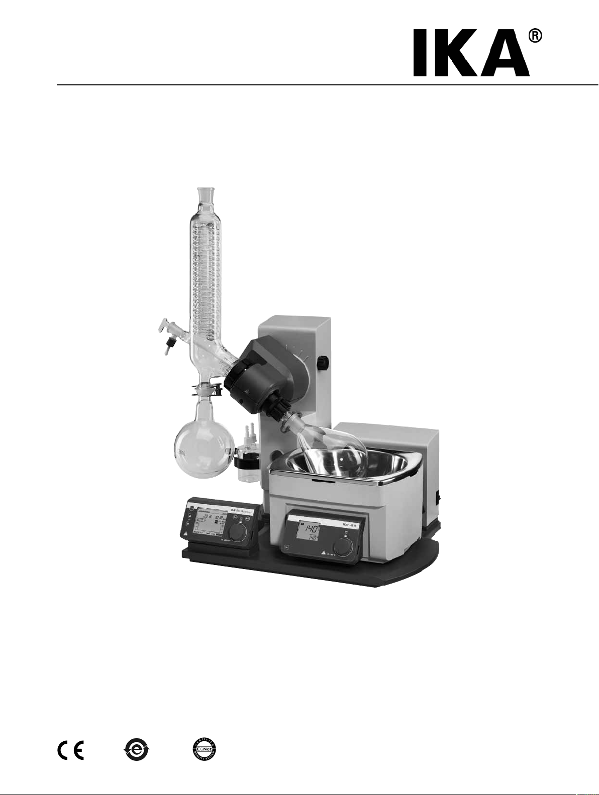
RV 10 control
IKA
Komplettaufbau mit Zubehör Schutzschild HB 10.1 und Schutzhaube HB 10.2
Device complete, incl. accessories HB 10.1 spray guard and HB 10.2 cover
L’appareil complet, incl. les accessoires HB 10.1 bouclier anti-projections et HB 10.2 capot de protection
Aparato completo, incl. accesorios HB 10.1 placa de protección y HB 10.2 cubierta de protección
Комплектная установка с дополнительным защитным экраном HB 10.1 и защитным колпаком HB 10.2
Pos. Bezeichung
A HB 10.2 Schutzhaube (nicht im Lieferumfang enthalten)
B HB 10.1 Schutzschild (nicht im Lieferumfang enthalten)
C Heizbad HB 10
D Antrieb RV 10 control
E Glassatz
F Halter
G Woulff’sche Flasche
Item Designation
A HB 10.2 Cover (not included in delivery)
B HB 10.1 Spray guard (not included in delivery)
C Heating bath HB 10
D Drive RV 10 control
E Glassware
F Bracket
G Woulff bottle
Pos. Désignation
A HB 10.2 Capot de protection
B HB 10.1 Bouclier anti-projections
C Bain chauffant HB 10
D Entraînement RV 10 control
E Verrerie
F Support
G Flacon de Woulfe
G
F
E
D
Pos. Designación
A HB 10.2 Cubierta de protección
B HB 10.1 Placa de protección
C Baño calefactor HB 10
D Accionamiento RV 10 control
E Equipo de vidrio
F Soporte
G Botella de Woulfe
(no incluido en volumen de entrega)
A
B
C
Fig. 1
(no incluido en volumen de entrega)
(pas compris dans la volume de livraison)
(pas compris dans la volume de livraison)
Поз. Наименование
A Защитный колпак HB 10.2 (не входит в комплект поставки)
B Защитный экран HB 10.1 (не входит в комплект поставки)
C Нагревательная баняt HB 10
D Привод RV 10 control
E Стеклянная посуда
F Держатель
G Склянка Вульфа
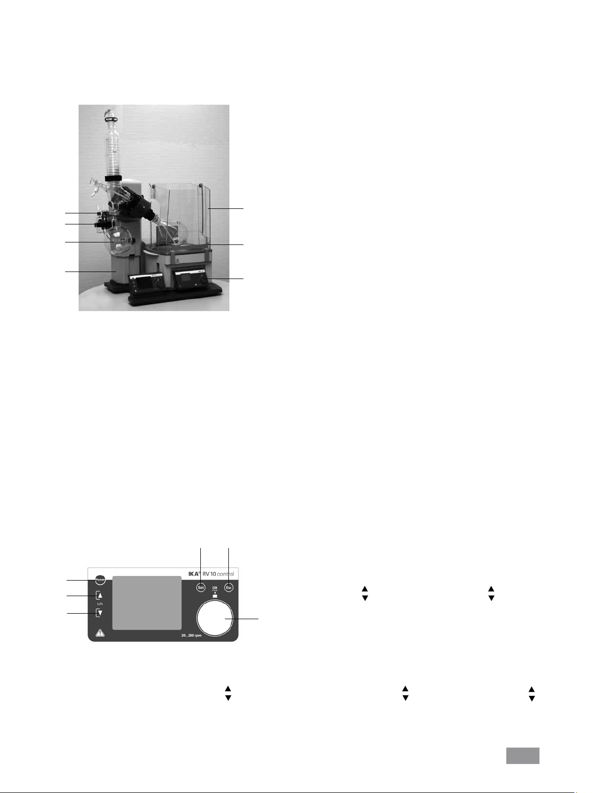
Funktionstasten / Function keys / Touches de fonction / Teclas de función / Функциональные кнопки
6
5
1
2
3
Pos. Designation
1 Touche "Power"
2 Touche de position du dispositif de levage "
3 Touche de position du dispositif de levage " "
4 Bouton rotatif/ Bouton-poussoir
5 Touche "Set"
6 Touche "Esc"
Pos. Bezeichung
1 Taste "Power"
2 Taste Liftposition " "
3 Taste Liftposition " "
4 Dreh-/ Drückknopf
5 Taste "Set"
4
6 Taste "Esc"
Fig. 2
Pos. Designación
"
1 Tecla "Power"
2 Tecla de la posición del elevador " "
3 Tecla de la posición del elevador " "
4 Dreh-/ Drückknopf
5 Tecla "Set"
6 Tecla "Esc"
Item Designation
1 "Power" key
2 Lift position " " key
3 Lift position " " key
4 Rotating/ Pressing knob
5 "Set" key
6 "Esc" key
Поз. Наименование
1 Кнопка питания «Power»
2 Кнопка положения подъемника « »
3 Кнопка положения подъемника « »
4 Dreh-/ Drückknopf
5 Кнопка питания "Set"
6 Кнопка питания "Esc"
4
Page 5
Ursprungssprache
DE
Inhaltsverzeichnis
Seite
EG-Konformitätserklärung 3
Zeichenerklärung 5
Gewährleistung 5
Sicherheitshinweise 6
Bestimmungsgemäßer Gebrauch 7
Auspacken 8
Wissenswertes 8
Vakuum-Regelung: 2-Punkt- und Drehzahlregelung 8
Aufstellung 10
Antrieb RV 10 control
Heizbad HB 10
Glassatz
Verschlauchung
Schnittstellen und Ausgänge 18
Inbetriebnahme 20
Wartung und Reinigung 32
Zubehör 32
Fehlercodes 35
Technische Daten 36
Lösemitteltabelle (Auswahl) 37
Zeichenerklärung
Allgemeiner Gefahrenhinweis
Verbrennungsgefahr!
Gewährleistung
Entsprechend den IKA®-Verkaufs- und Lieferbedingungen beträgt die
Gewährleistungzeit 24 Monate. Im Gewährleistungsfall wenden Sie sich
bitte an Ihren Fachhändler. Sie können aber auch das Gerät unter Beifügung der Lieferrechnung und Nennung der Reklamationsgründe direkt
an unser Werk senden. Frachtkosten gehen zu Ihren Lasten.
Die Gewährleistung erstreckt sich nicht auf Verschleißteile und gilt nicht
für Fehler, die auf unsachgemäße Handhabung und unzureichende Pflege und Wartung, entgegen den Anweisungen in dieser Betriebsanleitung, zurückzuführen sind.
5
Page 6
Sicherheitshinweise
Zu Ihrem Schutz
• Beachten Sie, dass nur geschultes Personal mit dem Gerät arbeitet.
• Beachten Sie die Sicherheitshinweise, Richtlinien, Arbeitsschutz-und
Unfallverhütungsvorschriften. Insbesondere bei Arbeiten unter
Vakuum!
• Tragen Sie Ihre persönliche Schutzausrüstung entsprechend der Ge-
fahrenklasse des zu bearbeitenden Mediums. Ansonsten besteht eine
Gefährdung durch:
- Spritzen von Flüssigkeiten,
- Erfassen von Körperteilen, Haaren, Kleidungsstücken und Schmuck,
- Verletzung durch Glasbruch.
• Beachten Sie eine Gefährdung des Anwenders durch Kontakt mit /
Einatmen von Medien, z.B. giftige Flüssigkeiten, Gase, Nebel, Dämpfe
oder Stäube oder biologische bzw. mikrobiologische Stoffe.
• Stellen Sie das Gerät frei auf einer ebenen, stabilen, sauberen, rutsch-
festen, trockenen, und feuerfesten Fläche auf.
• Achten Sie auf genügende Höhenfreiheit, da der Glasaufbau die Ge-
rätehöhe überschreiten kann.
•
Prüfen Sie vor jeder Verwendung Gerät, Zubehör und insbesondere
Glasteile auf Beschädigungen. Verwenden Sie keine beschädigten Teile.
• Achten Sie auf einen spannungsfreien Glasaufbau! Berstgefahr durch:
- Spannungen infolge von fehlerhaftem Zusammenbau,
- mechanische Einwirkungen von außen,
- durch örtliche Temperaturspitzen.
• Achten Sie darauf, dass das Gerät aufgrund von Vibrationen bzw. Un-
wucht nicht zu wandern beginnt.
• Beachten Sie eine Gefährdung durch:
- entzündliche Materialien
- brennbare Medien mit niedriger Siedetemperatur.
Die eingestellte Sicherheitstemperaturbegrenzung des Heizbades muss
immer mindestens 25 °C unterhalb des Brennpunktes des verwendeten
Mediums liegen.
• Betreiben Sie das Gerät nicht in explosionsgefährdeten Atmosphären,
mit Gefahrstoffen und unter Wasser.
• Bearbeiten Sie nur Medien, bei denen der Energieeintrag durch das
Bearbeiten unbedenklich ist. Dies gilt auch für andere Energieeinträge,
z.B. durch Lichteinstrahlung.
• Arbeiten mit dem Gerät dürfen nur im überwachten Betrieb durchge-
führt werden.
• Der Betrieb mit Überdruck ist nicht zulässig (Kühlwasserdruck siehe
“Technische Daten”).
• Decken Sie die Lüftungsschlitze zur Kühlung des Gerätes nicht zu.
• Zwischen Medium und Antriebseinheit können elektrostatische Vor-
gänge ablaufen und zu einer Gefährdung führen.
• Das Gerät ist nicht für den Handbetrieb geeignet.
• Sicheres Arbeiten ist nur mit Zubehör, das im Kapitel “Zubehör” be-
schrieben ist, gewährleistet.
• Beachten Sie die Betriebsanleitung des Heizbades HB 10.
• Beachten Sie die Betriebsanleitung des Zubehörs z.B. Vakuumpumpe.
• Verlegen Sie den druckseitigen Ausgang der Vakuumpumpe in den
Laborabzug.
• Verwenden Sie die Schutzhaube HB 10.2 bzw. das Spritzschutzschild
HB 10.1.
• Betreiben Sie das Gerät nur unter einem allseitig geschlossenen Abzug
oder vergleichbaren Sicherheitseinrichtungen.
• Lesen Sie die Betriebsanleitung vor Inbetriebnah me vollständig und beachten Sie die Sicherheits hinweise.
• Bewahren Sie die Betriebsanleitung für Alle zugänglich
auf.
• Achtung! Mit diesem Gerät dürfen nur Medien be-
arbeitet bzw. erhitzt werden, deren Flammpunkt über
der eingestellten Sicherheitstemperaturbegrenzung des
Heizbades liegt.
• Passen Sie die Menge und Art des Destillationsgutes an die Größe der
Destillationsapparatur an. Der Kühler muss ausreichend wirksam sein.
Überwachen sie den Kühlmitteldurchfluss am Ausgang des Kühlers.
• Belüften Sie immer den Glasaufbau bei Arbeit unter Normaldruck (z.B.
offener Ausgang am Kühler), um einen Druckaufbau zu verhindern.
• Beachten Sie, dass Gase, Dämpfe oder Schwebstoffe in gefährlicher
Konzentration durch den offenen Ausgang am Kühler entweichen können. Stellen Sie sicher, dass eine Gefährdung ausgeschlossen ist, z.B.
durch nachgeschaltete Kühlfallen, Gaswaschflaschen oder eine wirksame Absaugung.
• Erhitzen Sie evakuierte Glasgefässe nicht einseitig. Der Verdampferkolben muss während der Heizphase rotieren.
• Der Glassatz ist für einen Vakuumbetrieb bis zu 1 mbar ausgelegt. Evakuieren Sie die Apparaturen vor Beginn des Aufheizens (siehe Kapitel
“Inbetriebnahme”). Belüften Sie die Apparaturen erst wieder nach dem
Abkühlen. Nicht kondensierte Dämpfe müssen auskondensiert oder
gefahrlos abgeführt werden. Besteht die Gefahr, dass sich der Destillationsrückstand in Gegenwart von Sauerstoff zersetzt, darf nur Inertgas
zum Entspannen eingelassen werden.
• Achtung! Vermeiden Sie Peroxidbildung. In den Destillations- und
Abdampfrückständen können sich organische Peroxide anreichern und
explosionsartig zersetzen!
Bewahren Sie Flüssigkeiten die zur Bildung organischer Peroxide nei-
gen, vor Licht - insbesondere UV-Strahlung - geschützt auf und untersuchen Sie sie vor der Destillation und dem Abdampfen auf Anwesenheit von Peroxiden. Vorhandene Peroxide müssen entfernt werden.
Zur Bildung von Peroxiden neigen zahlreiche organische Verbindungen,
z.B. Dekalin, Diethylehter, Dioxan, Tetrahydrofuran, ferner ungesättigte
Kohlenwasserstoffe, wie Tetralin, Diene, Cumol sowie Aldehyde, Ketone, und Lösungen dieser Stoffe.
• Verbrennungsgefahr! Das Heizbad, das Temperiermedium sowie der
Verdampferkolben und Glasaufbau können während dem Betrieb und
längere Zeit danach heiß sein! Lassen Sie die Komponenten vor weiteren Arbeiten am Gerät abkühlen.
• Achtung! Vermeiden Sie Siedeverzug. Das Aufheizen des Verdampfer-
kolbens im Heizbad ohne Zuschalten des Rotationsantriebes ist nicht
zulässig! Zeigen sich durch plötzliches Schäumen oder Ausgasen Anzeichen für eine beginnende Zersetzung des Kolbeninhaltes, schalten
Sie sofort die Beheizung aus. Heben Sie den Verdampferkolben durch
die Hubvorrichtung aus dem Heizbad. Räumen Sie den gefährdeten
Bereich und warnen Sie die Umgebung!
• Achtung! Betreiben Sie das Gerät niemals mit rotierendem Verdamp-
ferkolben und angehobenem Lift. Starten Sie mit niedriger Drehzahl
und senken Sie den Verdampferkolben in das Heizbad, erhöhen Sie
dann auf die gewünschte Drehzahl. Ansonsten besteht eine Gefährdung durch Herausspritzen von heißem Temperiermedium!
• Stellen Sie die Drehzahl des Antriebes so ein, dass durch den drehenden Verdampferkolben im Heizbad kein Temperiermedium herausgeschleudert wird und reduzieren Sie gegebenenfalls wieder die Drehzahl.
• Fassen Sie während des Betriebes nicht an rotierende Teile.
Unwuchten können zu unkontrolliertem Resonanzverhalten des Gerä-
•
tes, bzw. des Aufbaus führen. Glasapparaturen können beschädigt oder
zerstört werden. Schalten Sie das Gerät bei Unwucht oder außergewöhnlichen Geräuschen sofort aus oder reduzieren Sie die Drehzahl.
• Unterdruck im Glassatz nach Stromausfall möglich! Gerät belüftet automatisch bei erneutem Einschalten!
• Nach einer Unterbrechung der Stromzufuhr läuft das Gerät nicht von
selbst wieder an.
• Eine Trennung vom Stromversorgungsnetz erfolgt bei dem Gerät nur
über das Betätigen des Geräteschalters bzw. das Ziehen des Netz - bzw.
Gerätesteckers.
• Die Steckdose für die Netzanschlussleitung muss leicht erreichbar und
zugänglich sein.
6
Page 7

• Automatisiertes Arbeiten: Verifizieren und überprüfen Sie Verdampfungsprozesse bevor Sie sie automatisiert ablaufen lassen. Unbekannte
Verdampfungsprozesse dürfen nicht automatisiert ablaufen!
Sicherheitsanhebung
Durch Abschalten des Gerätes oder durch Trennen der Stromversorgung
tritt die interne Sicherheitsanhebung in Kraft und hebt den Verdampferkolben aus dem Heizbad.
Die Sicherheitsanhebung im stromlosen Zustand ist für ein maximales
Gesamtgewicht (Glassatz plus Lösemittel) von 3,1 kg ausgelegt.
Beispiel für die Berechnung der maximalen Zuladung bei einem vertikalen
Glassatz mit 1 Liter Kolben:
Kühler + Auffangkolben + Verdampferkolben + Kleinteile =
1200 g
+ 400 g + 280 g + 100 g = 1980 gr
Maximale Zuladung an Lösemittel = 3100 g – 1980 g = 1320 g
Eine Sicherheitsanhebung bei höheren Zuladungen kann bauartbedingt
nicht sichergestellt werden!
Bei Verwendung anderer Kühlerarten wie z.B. Trockeneis- oder Intensivkühler, sowie bei Verwendung von Rückflussdestillation-Verteilerstücken
mit Aufsteckkühler kann es notwendig sein, die Zuladung entsprechend
dem Mehrgewicht dieser Glasaufbauten zu reduzieren!
Überprüfen Sie deshalb vor Destillationsbeginn, ob der mit Glassatz und
Destillationsgut bestückte Lift im stromlosen Zustand nach oben fährt.
Die Sicherheitsanhebung muss vor dem Betrieb täglich überprüft werden. Fahren Sie den Lift motorisch in die untere Endlage und betätigen
Sie die „Power“ Taste auf dem Frontschild oder den Netzhauptschalter
Neben dem manuellen Betrieb können folgende automatisierten Modi
gewählt werden:
- 100% Destillation,
- Volumen- bzw. mengenabhängige Destillation.
an der hinteren rechten Geräteseite mit dem maximalen Gesamtgewicht
von 3,1 kg.
Der Verdampferkolben wird aus dem Heizbad gehoben.
Bei Erstinbetriebnahme sowie nach längerem Stillstand gehen Sie bitte
folgendermaßen vor: Fahren Sie den Lift mehrmals motorisch in die untere und obere Endlage durch Betätigen der Liftfunktionstasten, bevor Sie
die Netzspannung unterbrechen.
Hinweis: Das Abschalten und der Wegbrechen der Netzspannung zeigt
ein zeitlich verzögertes Verhalten gegenüber dem Abschalten an dem
„Power“ Schalter auf der Frontfolie.
Sollte die Sicherheitsanhebung nicht funktionieren, kontaktieren Sie bitte
®
- Serviceabteilung.
die IKA
Verdampferseitig (Verdampferkolben plus Inhalt) beträgt das maximale
zulässige Gewicht 3,0 kg! Größere Zuladungen bergen die Gefahr von
Glasbruch am Dampfdurchführungsrohr!
Beachten Sie, dass hierbei die Sicherheitsanhebung ausser Kraft gesetzt
ist.
Arbeiten Sie bei großen Zuladungen immer mit langsamen Drehzahlen.
Große Unwuchtskräfte führen zum Bruch des Dampdurchführungsrohres!
Zum Schutz des Gerätes
• Spannungsangabe des Typenschildes muss mit der Netzspannung
übereinstimmen.
• Steckdose muss geerdet sein (Schutzleiterkontakt).
• Das Gerät darf nur von einer Fachkraft geöffnet werden.
Bestimmungsgemäßer Gebrauch
• Verwendung
Das Gerät ist in Verbindung mit dem von IKA® empfohlenen Zubehör
geeignet für:
- Schnelle und schonende Destillation von Flüssigkeiten
- Eindampfen von Lösungen und Suspensionen
- Kristallisation, Synthese oder Reinigung von Feinchemikalien
- Pulver- und Granulattrocknung
- Recycling von Lösungsmittel
Betriebsart: Tischgerät
• Abnehmbare Geräteteile müssen wieder am Gerät angebracht werden,
um das Eindringen von Fremdkörpern, Flüssigkeiten etc. zu verhindern.
• Vermeiden Sie Stöße und Schläge auf das Gerät oder Zubehör.
• Verwendungsgebiet
- Laboratorien - Schulen
- Apotheken - Universitäten
Der Schutz für den Benutzer ist nicht mehr gewährleistet, wenn das Gerät mit Zubehör betrieben wird, welches nicht vom Hersteller geliefert
oder empfohlen wird oder wenn das Gerät in nicht bestimmungsgemäßem Gebrauch entgegen der Herstellervorgabe betrieben wird oder
wenn Veränderungen an Gerät oder Leiterplatte durch Dritte vorgenommen werden.
7
Page 8

• Auspacken
- Packen Sie das Gerät vorsichtig aus
- Nehmen Sie bei Beschädigungen sofort den Tatbestand auf
(Post, Bahn oder Spedition)
• Lieferumfang
siehe Tabelle
Auspacken
Antrieb RV 10 control
Heizbad HB 10
Glassatz vertikal RV 10.1
Glassatz vertikal RV 10.10 beschichtet
Woulff’sche Flasche
Halterung
Kühlersicherung kompl.
Vakuumschlauch (2 x 0,55 m)
Wasserablassschlauch (1 x 1 m)
Betriebsanleitung
Ringschlüssel
RV 10 control V x x x x x x x x x x x x
RV 10 control V-C x x x x x x x x x x x x
RV 10 control FLEX x x x x x x x x x x x
RV 10 control V auto x x x x x x x x x x x x
RV 10 control V-C auto x x x x x x x x x x x x
RV 10 control FLEX auto x x x x x x x x x x x
Griff
RV 10.4002 Vakuumventil für Laborvakuum
Vakuumpumpe N 920 speed controlled
Wissenswertes
Destillation ist ein thermisches Trennverfahren für flüssige Stoffverbindungen auf Grundlage stoffspezifischer, druckabhängiger Siedepunkte
durch Verdampfen und anschließender Kondensation.
Die Siedepunkttemperatur verringert sich mit sinkendem äußerem Druck,
so dass in der Regel bei vermindertem Druck gearbeitet wird. So kann
das Heizbad bei konstanter Temperatur (z.B. 60 °C) gehalten werden.
Über das Vakuum wird nun der Siedepunkt bei einer Dampftemperatur
von ca. 40 °C eingestellt. Das Kühlwasser für den Kondensationskühler
sollte nicht wärmer als 20 °C sein (60-40-20 Regel).
Zur Vakuumerzeugung sollte eine chemiefeste Membranpumpe mit
Vakuumcontroller eingesetzt werden, die durch Vorschalten einer
Woulff’schen Flasche und/oder eines Vakuumabscheiders vor Lösemittelrückständen geschützt wird.
Das Arbeiten mit einer Wasserstrahlpumpe zur Vakuumerzeugung kann
nur bedingt empfohlen werden, da bei diesen Systemen eine Kontamination der Umwelt durch Lösemittel stattfinden kann.
Die Verdampferleistung wird durch Drehzahl, Temperatur, Kolbengröße
und Systemdruck beeinflusst.
Die optimale Auslastung des Durchlaufkühlers liegt bei ca. 60%.
Dies entspricht einer Kondensation an ca. 2/3 der Kühlwendel. Bei größerer Auslastung besteht die Gefahr, dass nicht kondensierter Lösemitteldampf abgesaugt wird.
Um dies zu verhindern, könnnen Sie die Sicherheitsüberwachung der
Kühlerauslastung aktivieren. Führen Sie hierzu mehrere Destillationen
durch und nehmen Sie den Wert aus dem Menü “Einstellungen, Menüpunkt “Antrieb”, Punkt “Maximale Kühlleistung”. Berechnen Sie die Kühlerleistung nach folgender Formel:
Grenzwert Kühlerleistung = Maximale Kühlerleistung * 1.3
Tragen sie diesen Wert in das Menü “Einstellungen”, Menüpunkt “Destillation”, Punkt “Grenzwert Kühlerleistung” ein. Das Gerät beendet anschließend bei Überschreitung des Grenzwertes des Kühlers die Messung
und gibt eine Fehlermeldung aus. Eine Veränderung der Konfiguration
des Kühleraufbaues oder der Destillationskonfiguration erfordert eventuell eine neue Anpassung der maximalen Kühlerauslastung.
Das Gerät ist mit einer Kolbenhub-Sicherheitsvorrichtung ausgestattet.
Der Glasaufbau kann nach Stromausfall evakuiert sein, und wird bei
Wiedereinschalten belüftet. Bei Stromausfall wird der Verdampferkolben
durch eine integrierte Gasdruckfeder automatisch aus dem Heizbad angehoben.
ACHTUNG! Die Sicherheitsanhebung muss vor dem Betrieb täglich
überprüft werden. Siehe hierzu Kapitel "Sicherheitshinweise - Sicherheitsanhebung"!
Mit dem Rotationsverdampfer RV 10 control können neben allen manuellen sowie halbautomatischen Verdampfungsoperationen auch vollautomatische und mengengesteuerte Verdampfungsprozesse gefahren
werden. Dazu ist das Gerät standardmäßig mit einem Vakuumcontroller,
Kühlwasserdifferenztemperaturmessfühler und einem Kühlwasserdurchflussmesser ausgestattet. Mit dem integrierten Vakuumcontroller kann
das Vakuum im 2-Punkt wie auch im drehzahlgeregelten Pumpen-Betrieb
geregelt werden. Das Gerät ist für den Betrieb an einer Kühlwasserversorgung (z.B. Laborthermostat) ausgelegt, kann jedoch auch an der Wasserleitung betrieben werden. Beachten Sie hierzu die Technischen Daten
hinsichtlich Kühlwasserdruck, -temperaturkonstanz und Durchfluss, wie
auch länderspezifische Vorschriften.
Bei Betrieb an einer Wasserleitung empfehlen wir das Wasserdrosselventil RV 10.5001!
Mit diesem Ventil kann der Kühlwasserdurchfluss eingestellt, sowie die
Kühlwasserzufuhr nach einer Destillation automatisch unterbrochen werden.
Mit dem Wasserfilter RV 10.5002 können Schmutzpartikel aus der Wasserleitung vor der Ventiltechnik zurückgehalten werden.
Zur Druckreduzierung empfehlen wir das Druckregelventil RV 10.5003
direkt nach der Abnahmestelle in die Leitung zu setzen.
Automatisierte volumenabhängige Destillation: Die Apparatur
muss auf Betriebstemperatur gebracht werden. Dies erreichen Sie durch
eine Probedestillation.
Die Werkseinstellung für diesen Wert sind 900 W.
8
Page 9
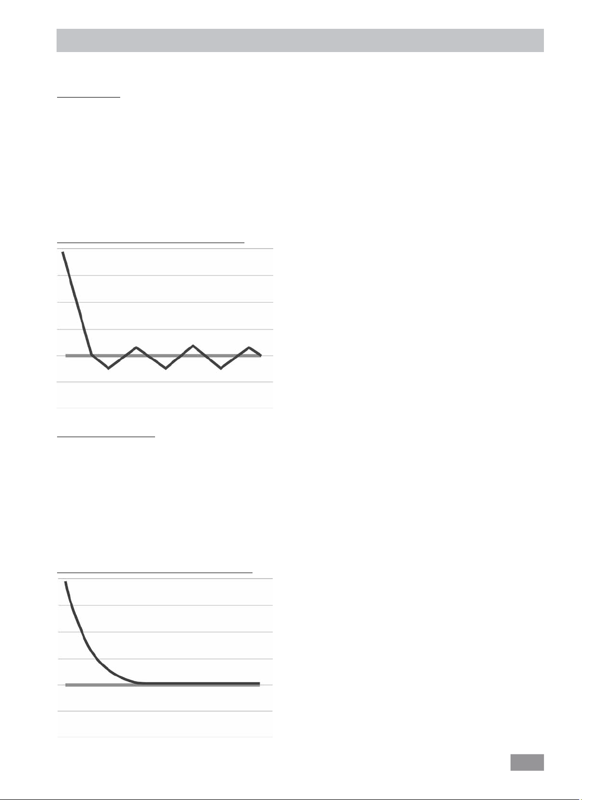
Vakuum-Regelung: 2-Punkt- und Drehzahlregelung
Der Rotationsverdampfer RV10 control bietet mit dem integrierten Vakuumcontroller und Drucksensor die Möglichkeit das gewünschte Vakuum mittels 2-Punkt Regelung oder per Drehzahlregelung einzustellen.
2-Punkt Regelung
Mittels Vakuumpumpe wird der Glassatz evakuiert. Die Vakuumpumpe läuft mit einer konstanten Drehzahl, die in der Regel auch nicht einstellbar ist.
Wird der eingestellte Sollwert erreicht, unterbricht das Vakuumventil RV 10.4002 die Saugleitung (Lieferumfang). Wird zusätzlich das automatische
An- und Abschalten der Vakuumpumpe gewünscht, benützen Sie bitte die Pumpensteuerung RV 10.4003 (Zubehör).
Bedingt durch die zeitliche Differenz von der Detektion des Vakuumwertes, Sollwertvergleich und Schalten des Vakuumventiles im Millisekundenbereich, wird der eingestellte Sollwert leicht unterschritten. Natürliche Leckage der Apparatur verursacht nun wieder ein Ansteigen des Druckwertes im
System, das wiederum durch den integrierten Drucksensor detektiert wird.
Bei Überschreiten des Sollwertes wird das Vakuumventil wieder geöffnet und die laufende Vakuumpumpe senkt den Druck wiederum ab. Die im Display angezeigte Druckkurve schwankt um den eingestellten Sollwert.
Die Druckdifferenz zwischen Zu- und Wegschalten des Ventiles kann über den Vakuum-Hysteresewert eingestellt werden (siehe Einstellung: Vakuum).
Standardmäßig ist der Wert auf 10 mbar eingestellt.
Die Güte der Regelung ist abhängig von der Saugleistung der Pumpe (Drehzahl), Dichtheit des Systems, und Signallaufzeiten der verwendeten Elektronik.
Mit der 2-Punkt Regelung ist keine automatische Siedepunkterkennung möglich.
Schematische Darstellung einer 2-Punkt Vakuumregelung
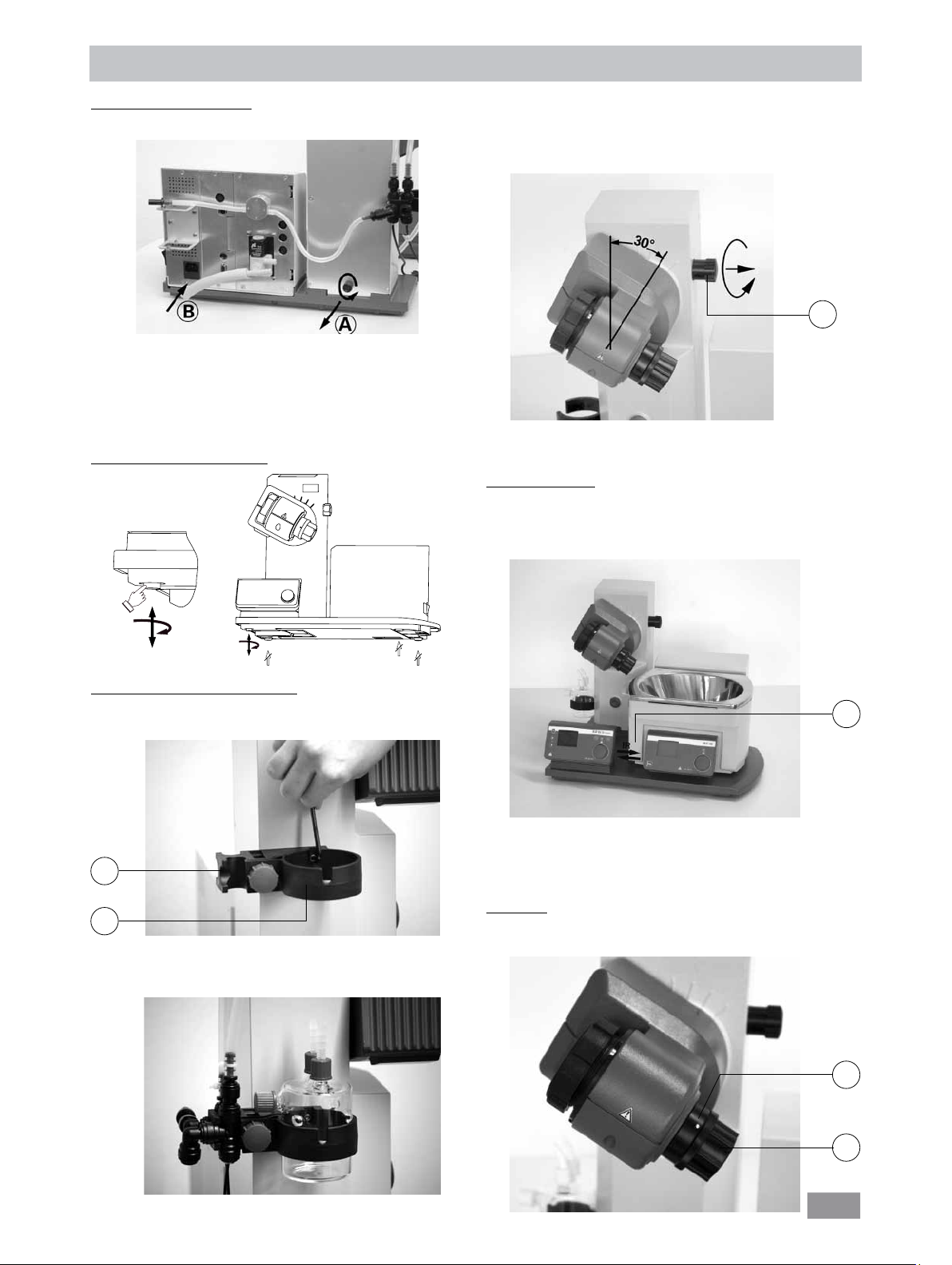
Drehzahl-Vakuum-Regelung
Die Ungenauigkeiten der 2-Punkt Regelung werden bei der Drehzahl-Vakuum-Regelung vermieden.
Für die Drehzahl-Vakuum-Regelung ist jedoch eine in der Drehzahl ansteuerbare Vakuumpumpe erforderlich, das Vakuumventil RV10.4002 wird nicht
benötigt und darf nicht angeschlossen werden!
Schließen Sie dafür die Vakuumpumpe (z.B. KNF N920 speed controlled pump) an der rückseitigen Schnittstelle an den Rotationsverdampfer an.
Bei dieser Regelungsart wird die Drehzahl der Pumpe, und damit ihre Saugleistung reduziert je näher der gemessene Druckwert bei dem Sollwert liegt.
Ist der Sollwert erreicht, läuft die Pumpe nur noch entsprechend der Leckrate.
Leiseres Arbeiten und genauere Vakuumregelung sind möglich.
Die Drehzahl-Vakuum-Regelung wird am RV 10 control automatisch eingestellt, sobald eine geeignete Vakuumpumpe angeschlossen ist.
Mit dieser Regelungsart ist eine automatische Siedepunkterkennung möglich, d.h das System sucht und hält im automatischen Modus den Siedepunkt
des Lösemittels.
Da im Gegensatz zur Volumenabhängigen Destillation das Lösemittel bei der automatischen Siedepunktserkennung nicht bekannt sein muss, schließen
sich diese unterschiedlichen Arbeitsmodi gegenseitig aus.
Schematische Darstellung einer Drehzahl-Vakuum-Regelung
9
Page 10
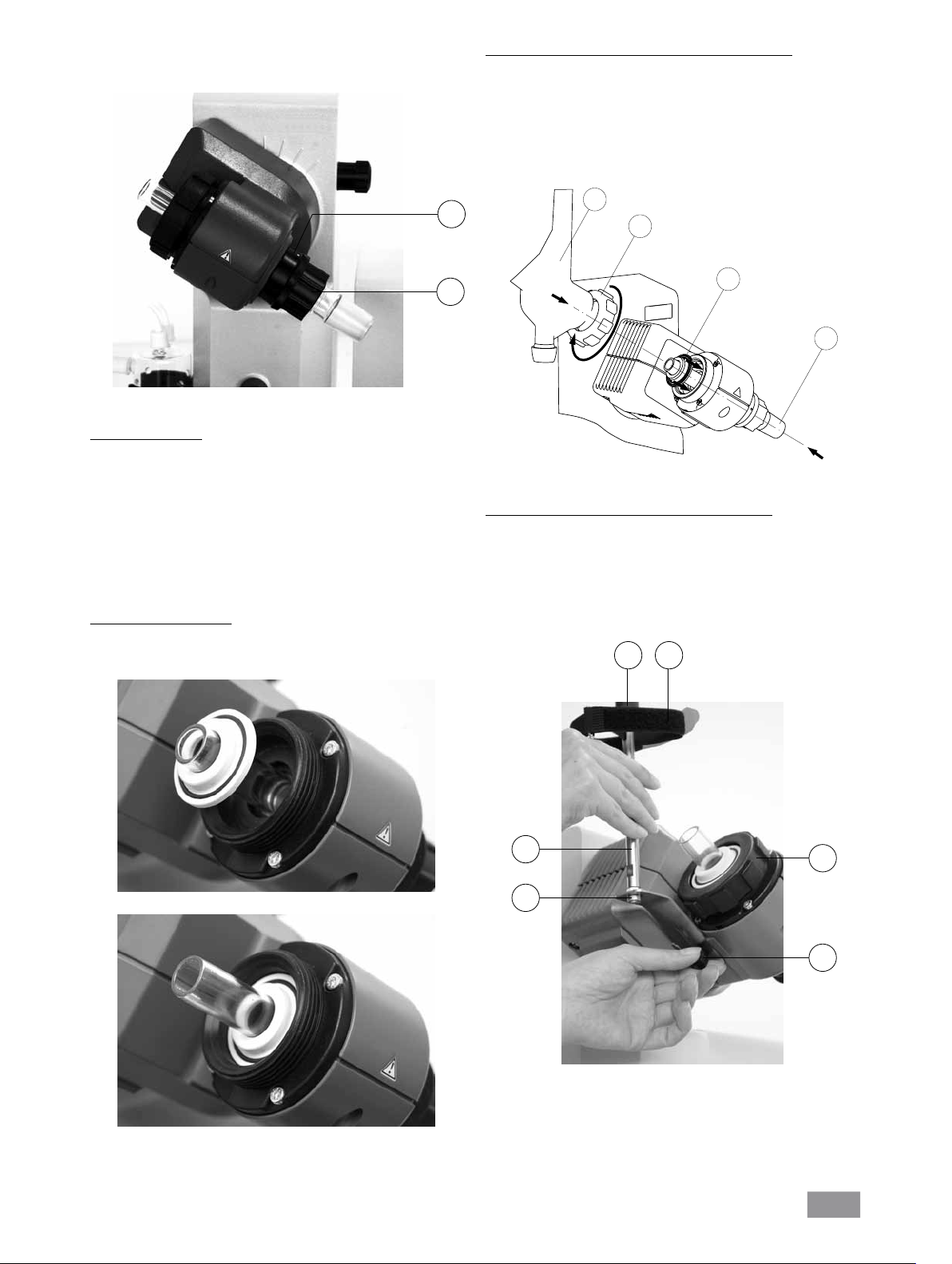
Aufstellung
Antrieb RV 10 control
Achtung! Transportsicherung lösen (Fig. 4a)!
Fig. 4a
Drücken Sie den Lift mit der Hand und entfernen Sie die Rändelschrau-
be auf der Geräterückseite (A).
Der Lift fährt nach Entfernen der Transsportsicherung langsam in seine
obere Endlage. Der Hub beträgt ca. 140 mm.
Schließen Sie das Gerät mit der mitgelieferten Netzanschlussleitung an
die Spannungsversorgung an (B).
Einstellbarer Gerätefuß (Fig. 4b)
Lösen Sie die Klemmvorrichtung zur Winkeleinstellung des Rotations-
antriebes auf der rechten Liftseite durch Drehen der Griffschraube (E)
gegen den Uhrzeigersinn (durch leichtes Drücken und gleichzeitiges
Drehen lässt sich die Griffschraube (E) weiter aus- bzw. einfahren).
Stellen Sie den Antrieb auf einen Winkel von ca. 30° (Fig. 7).
E
Sichern Sie anschließend den Rotationsantrieb gegen Verdrehung
durch Anziehen der Griffschraube im Uhrzeigersinn.
Fig. 7
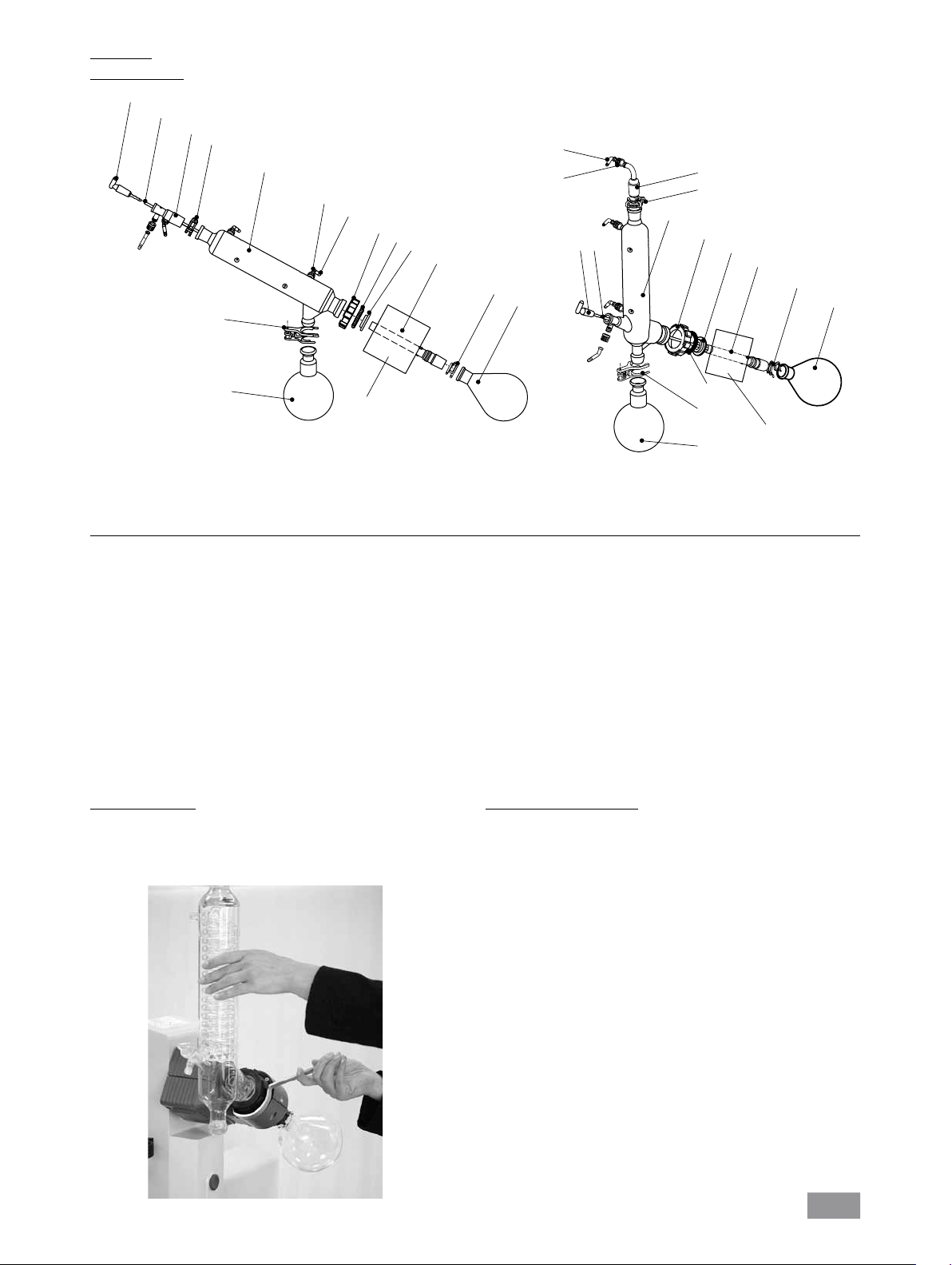
Heizbad HB 10
Achtung! Beachten Sie die Betriebsanleitung des Heizbades, Kapitel “In-
betriebnahme”!
Stellen Sie das Heizbad auf die Stellfläche des Rotationsantriebes und
schieben sie es in die linke Position (Fig. 8).
Fig. 4b
Montage Woulff’sche Flasche (Fig. 5)
Montieren Sie das Schlauchverbindungsstück (C) an die linke Liftseite.
Montieren Sie den Halter (D) an das Schlauchverbindungsstück (C).
C
D
Fig. 5
Setzen Sie die Flasche ein und montieren Sie die mitgelieferten
Schlauchanschlüsse an die Flasche (Fig. 6).
F
Fig. 8
Hinweis: Der Datenaustausch zwischen Antriebseinheit und Heizbad findet mittels einer Infrarot- Schnittstelle (F) statt. Beachten Sie, dass die
Kommunikation nur bei freier, nicht unterbrochener Lichtstrecke gewährleistet ist!
Glassatz
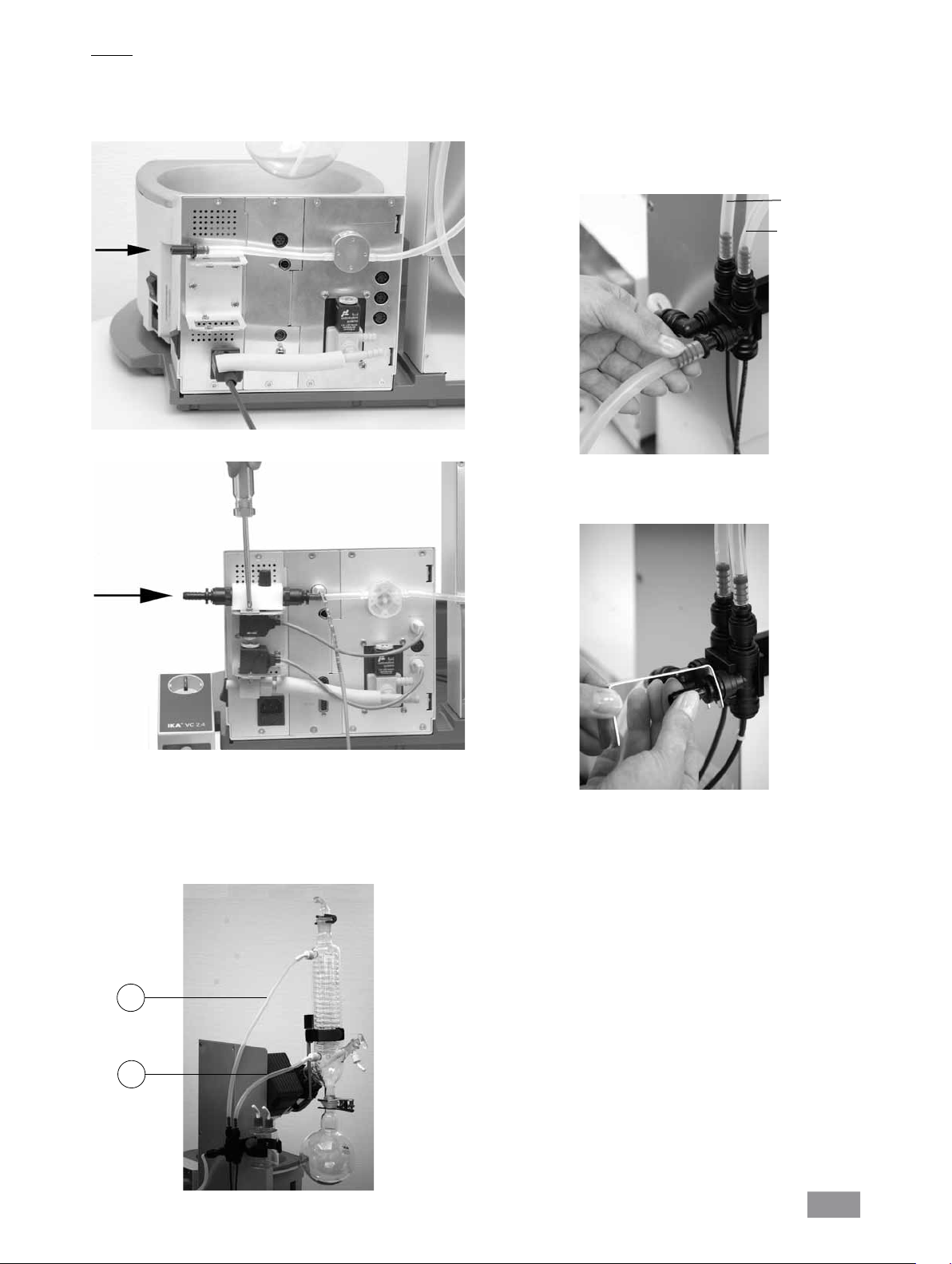
Öffnen Sie die Arretierung des Dampfdurchführungsrohres (G) durch
Drehung um 60° gegen den Uhrzeigersinn (Fig. 9).
G
Fig. 6
Fig. 9
H
10
Page 11
Führen Sie das Dampfdurchführungsrohr bis auf Anschlag ein.
Verriegeln Sie anschließend diese Arretierung durch Drehen um 60°
im Uhrzeigersinn (Fig. 10).
G
Erstinbetriebnahme - Montage der Dichtung RV 10.8001
Dampfdurchführungsrohr einsetzen (1).
Dichtung RV 10.8001 einsetzen (2).
Überwurfmutter (3b) über den Flansch des Kühlers (3a) schieben.
Ringfeder (3c) ebenfalls über den Flansch des Kühlers (3a) schieben
Kühlers (3a) auf die Dichtung (2) aufsetzen.
Überwurfmutter handfest anziehen (3b).
Hinweis: Beachten Sie die Montageanleitung des Glassatzes.
3a
3b
H
Fig. 10
Überprüfen Sie die axiale Arretierung des Dampfdurchführungsrohres.
Abdrückvorrichtung
Die Kunststoffmutter (H) dient als Abdrückhilfe für festsitzende Kol-
benschliffverbindungen (Fig. 10).
Halten Sie die Arretierung (G) und lösen Sie die Kunststoffmutter (H).
Halten Sie hierzu den festsitzenden Verdampferkolben und drehen Sie
die Kunststoffmutter (H) bis zum Verdampferkolbenhals.
Hinweis: Ziehen Sie vor Inbetriebnahme die Kunststoffmutter (H) links-
bündig handfest an. Dabei halten Sie die Arretierung (G) des Dampfdurchführungsrohres fest.
Kühlerdichtung einsetzen
Setzen Sie die Kühlerdichtung RV 10.8001 in die Kühleraufnahme und
montieren Sie nun den Glassatz entsprechend seiner Montageanleitung an das Gerät (Fig. 11 a,b und c ).
2
1
Fig. 11c
Montage Kühlersicherung des vertikalen Glassatzes
Montieren Sie die Kühlersicherung gemäß der Abbildung (Fig. 12).
Montieren Sie das Blech (I) mit der Rändelschraube (J).
Stecken Sie den Stativstab (L) auf das Blech (I) und fixieren Sie es mit
der Mutter (K).
Bringen Sie den Gummischutz (M) an.
Befestigen Sie das Klettband (N) am Stativstab (L).
Sichern Sie den vertikalen Glassatz mit dem Klettband (N).
M N
Fig. 11a
Fig. 11b
L
I
K
J
Fig. 12
11
Page 12
Glassatz
Montage Glassatz
4
5
Glassatz
RV 10.2 diagonal
7
RV 10.20 diagonal, beschichtet
8
6
12
13
15
16
9
3
2
10
Glassatz
RV 10.1 vertikal
RV 10.10 vertikal, beschichtet
13
12
5
4
7
8
6
15
9
3
2
10
11
1
Rotationsantrieb
NS29/32
ml
0
0
10
16
11
NS29/32
Rotationsantrieb
ml
0
0
10
1
Pos. Bezeichnung Menge Menge
Glassatz diagonal Glassatz vertikal
1 Auffangkolben 1 1
2 Klemme NS 29 1 1
3 Dampfdurchführungsrohr 1 1
4 Absperrhahn 1 1
5 Rohr 1 1
6 Kühler 1 Diagonalkühler 1 Vertikalkühler
7 Anschluss 1 Einleithülse 1 Vakuumanschluss
8 Klemme NS 29 1 1
9 Dichtung RV 10.8001 1 1
10 Verdampferkolben 1000 ml 1 1
11 Kugelschliff-Klammer RV 05.10 1 1
12 Schraubverbindung Kappe 4 4
13 Schlauchanschluss 4 4
15 Sicherungsmutter 1 1
16 Federring 1 1
Demontage Kühler
Verwenden Sie den mitgelieferten Ringschlüssel zum Lösen festsitzen-
der Überwurfmuttern.
Lösen Sie die Überwurfmutter durch Drehen gegen den Uhrzeigersinn.
Lösen Sie das Klettband.
Beschreibung Sonderkühler
• RV 10.3 Vertikal-Intensivkühler mit Verteilerstück
Mit Doppelmantel ausgeführter Vertikal-Intensivkühler, ermöglicht be-
sonders effiziente Kondensationen.
Auch in beschichteter Ausführung erhältlich (RV10.30).
Fig. 13
• RV 10.4 Trockeneiskühler
Trockeneiskühler zur Destillation von tiefsiedenden Lösungsmitteln.
Kühlung durch Trockeneis, kein Kühlwasser notwendig, maximale Kon-
densation durch tiefe Temperaturen.
Auch in beschichteter Ausführung erhältlich (RV10.40).
Nicht einsetzbar im automatischen Modus des RV10 control.
• RV 10.5 Vertikalkühler mit Verteilerstück und Absperrventil für die
Rückflussdestillation
Auch in beschichteter Ausführung erhältlich (RV10.50).
• RV 10.6 Vertikal-Intensivkühler mit Verteilerstück und Absperr-
ventil für die Rückflussdestillation
Mit Doppelmantel ausgeführter Vertikal-Intensivkühler, ermöglicht be-
sonders effiziente Rückflussdestillationen.
Auch in beschichteter Ausführung erhältlich (RV10.60).
12
Page 13
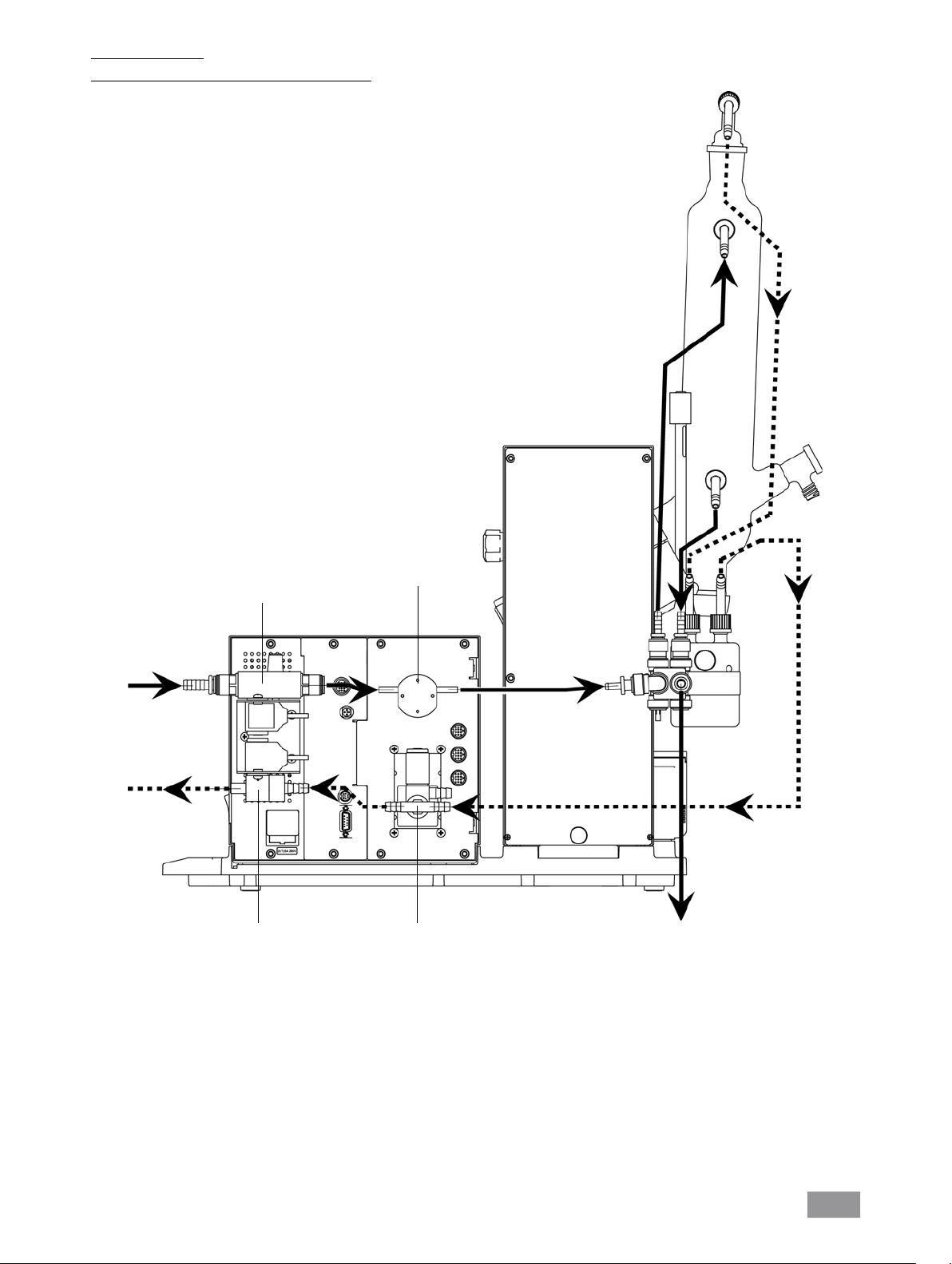
Verschlauchung
Schematische Darstellung Verschlauchung (Rückansicht)
Wasser
Vakuum
RV 10.5001
Drosselventil
Wasser
optional
RV 10.4002
Vakuumventil
Durchfluss-
messer
und
Belüftungsventil
WasserDrucksensor
Fig. 14
13
Page 14
Vakuum - 2-Punkt-Regelung
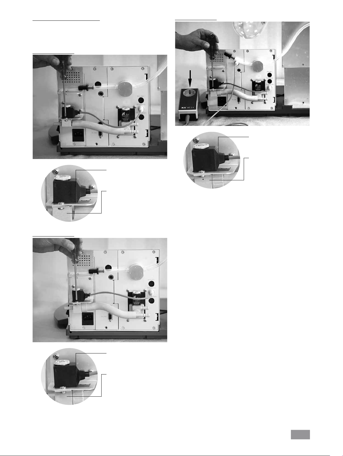
Montieren Sie eines der optionalen Vakuumventile RV 10.4001 bzw.
RV 10.4002 oder RV 10.4003 entsprechend Ihrer Vakuumanlage in die
dafür vorgesehene Halterung und verbinden Sie den Vakuumschlauch
mit dem Ventil (Fig. 15a,b,c).
Anschluss RV 10.4001
Anschluss RV 10.4003
Netzversorgung
Pumpe
Fig. 15c
Spule frei drehbar
Anschluss RV 10.4002
Fig. 15a
Spule frei drehbar
Saugrichtung entspricht der
Kennzeichnung durch den
Pfeil!
Achten Sie auf die Einbaulage!
Saugrichtung entspricht der
Kennzeichnung durch den
Pfeil!
Achten Sie auf die Einbaulage!
Fig. 15b
Spule frei drehbar
Saugrichtung entspricht der
Kennzeichnung durch den
Pfeil!
Achten Sie auf die Einbaulage!
14
Page 15
Vakuum - Drehzahlgeregelter Betrieb
Für einen Vakuum Regelbetrieb mit drehzahlgeregelter Pumpe wird
kein zusätzliches Ventil benötigt. Schließen Sie den Saugschlauch der
Pumpe direkt an den Schlauchanschluss des Drucksensors an.
Verbinden Sie die elektrische Steuerleitung mit dem RV10 control (Fig. 15e).
Fig. 15d
Fig. 15e
Anschluss RV10 Temperaturmessfühler (dT)
Schließen Sie den Temperaturmessfühler an der unteren Buchse (dT) an.
Achten Sie auf die Pfeilkennzeichnung.
Fig. 15f
dT
15
Page 16
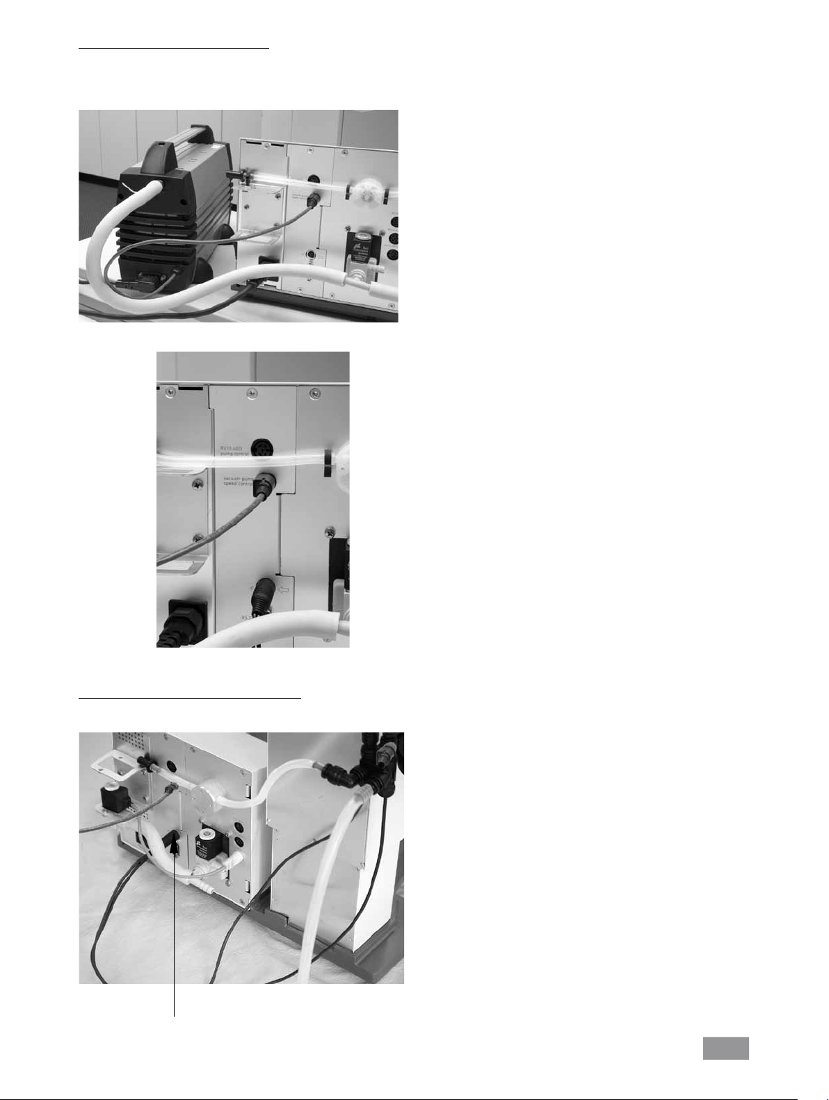
Wasser
Schließen Sie den Wasserzulauf an Ihre Wasserversorgung an (Fig. 16a;
Fig. 16b mit optionalem Drosselventil Wasser RV 10.5001). Beachten Sie
die technischen Daten zur Wasserversorgung.
Das Drosselventil Wasser RV 10.5001 ist nicht geeignet für den Betrieb
am Kühlaggregat, da der Durchfluss zu stark reduziert wird.
Wasserzulauf
Fig. 16a
Schließen Sie den mitgelieferten Wasserablassschlauch durch Stecken
des Nippels bis zum Anschlag in die Anschlussbuchse (Fig. 18).
Achtung! Achten Sie auf den korrekten Anschluss von Zu- und Ablauf
des Kühlers.
Werden die Wasserzulauf- bzw. Wasserablaufschläuche nicht entspre-
chend der Beschreibung bzw. Abbildung Fig. 14 montiert, sind automatische Destillationen nicht durchführbar, da die Temperaturwerte für
Zu- bzw. Ablauf falsch ermittelt werden.
Zulauf Kühler
Ablauf Kühler
Fig. 18
Lösen Sie die Schlauchverbindung mit dem im Lieferumfang enthalte-
nen Griff.
Wasserzulauf
Fig. 16b
Schließen Sie die Wasserschläuche am Glaskühler an (Kurzer Schlauch
(O) = Ablauf unten, langer Schlauch (P) = Zulauf oben) und fixieren Sie
die Schläuche (Fig. 17).
Hinweis: Sonderkühler siehe Abschnitt “Beschreibung Sonderkühler”.
P
Fig. 19
O
Fig. 17
16
Page 17
Schematische Darstellung Anschluss Rückseite
Stecken Sie das Ventilanschlusskabel (RV 10.5001 oder RV 10.4001/2, bzw. RV 10.4003 Valve) bzw. das Anschlusskabel (RV 10.4003 Pump control)
in die vorgesehene Buchse (Fig. 20) oder schließen Sie die drehzahlgeregelte Vakuumpumpe an. Damit wechselt der RV10 control automatisch in den
Drehzahl-Vakuum-Regelbetrieb.
Fig. 20
Verbinden Sie den Drucksensor und die Woulff’sche Flasche, sowie die
Woulff’sche Flasche und den Vakuumanschluss des Kühlers mit den im
Lieferumfang enthaltenen Vakuumschläuchen. Beachten Sie, dass das
Vakuum immer am höchsten Anschlusspunkt des Kühlers angeschlossen
wird (Fig. 21).
Fig. 21
17
Page 18
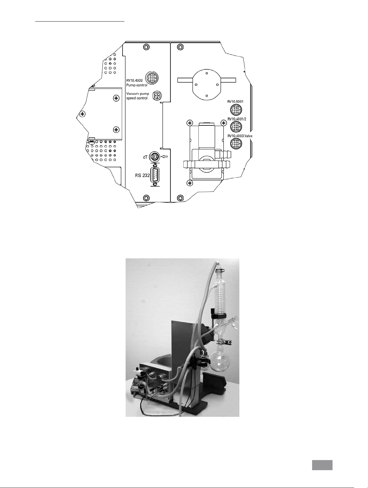
Schnittstellen und Ausgänge
HB 10
Die Datenkommunikation zwischen Heizbad und Antriebseinheit erfolgt
durch die IR-Schnittstelle. Diese befinden sich an der linken Displayseite des Heizbades bzw. an der rechten Displayseite der Antriebseinheit.
Stellen Sie keine Gegenstände zwischen die zwei Bedieneinheiten, da
ansonsten die Datenübertragung gestört ist (Fig. 22)!
IR
Fig. 22
RV10 control
Das Gerät kann im Modus “Remote” über RS 232 oder USB-Schnittstelle
mit der Laborsoftware labworldsoft® betrieben werden.
Die Schnittstelle RS 232 auf der Geräterückseite, siehe Fig. 20, ausgerüstet mit einem 9-poligen SUB-D-Buchse, kann mit einem PC verbunden
werden. Die Pins sind mit seriellen Signalen belegt.Die USB-Schnittstelle
befindet sich an der linken Displayseite der Antriebseinheit und kann mit
dem im Lieferumfang enthaltenen USB-Kabel mit einem PC verbunden
werden.
Hinweis: Beachten Sie hierzu die Systemvoraussetzungen sowie die Betriebsanleitung und Hilfestellungen der Software.
USB Schnittstelle
Der Universal Serial Bus (USB) ist ein serielles Bussystem zur Verbindung
des RV 10 control mit dem PC (Fig. 23). Mit USB ausgestattete Geräte
können im laufenden Betrieb miteinander verbunden (Hot-Plugging) und
angeschlossene Geräte und deren Eigenschaften automatisch erkannt
werden.
Die USB-Schnittstelle dient in Verbindung mit labworldsoft®
zum”Remote”-Betrieb und für das Update der Lösemittelbibliothek. Zum
Updaten wählen Sie http://www.ika.net/ika/lws/download/RV10.cfg.
Serielle Schnittstelle RS 232 (V24)
Konfiguration
- Die Funktion der Schnittstellen-Leitungen zwischen Gerät und Automatisierungssystem sind eine Auswahl aus den in der EIA-Norm RS232 C,
entsprechend DIN 66 020 Teil 1 spezifizierten Signale.
- Für die elektrischen Eigenschaften der Schnittstellen- Leitungen und die
Zuordnung der Signalzustände gilt die Norm RS 232 C, entsprechend
DIN 66 259 Teil 1.
- Übertragungsverfahren: Asynchrone Zeichenübertragung im Start-Stop
Betrieb.
- Übertragungsart: Voll Duplex.
- Zeichenformat: Zeichendarstellung gemäß Datenformat in DIN 66 022
für Start-Stop Betrieb. 1 Startbit; 7 Zeichenbits; 1Paritätsbit (gerade =
Even); 1 Stopbit.
- Übertragungsgeschwindigkeit: 9600 Bit/s.
- Datenflusssteuerung: none
- Zugriffsverfahren: Eine Datenübertragung vom Gerät zum Rechner erfolgt nur auf Anforderung des Rechners.
Befehlssyntax und Format
Für den Befehlssatz gilt folgendes:
- Die Befehle werden generell vom Rechner (Master) an das Gerät (Slave)
geschickt.
- Das Gerät sendet ausschließlich auf Anfrage des Rechners. Auch Fehlermeldungen können nicht spontan vom Gerät an den Rechner (Automatisierungssystem) gesendet werden.
- Die Befehle werden in Großbuchstaben übertragen.
- Befehle und Parameter sowie aufeinanderfolgende Parameter werden
durch wenigstens ein Leerzeichen getrennt (Code: hex 0x20).
- Jeder einzelne Befehl (incl. Parameter und Daten) und jede Antwort werden mit Blank CR LF abgeschlossen (Code: hex 0x20 hex 0x0d hex 0x0A)
und haben eine maximale Länge von 80 Zeichen.
- Das Dezimaltrennzeichen in einer Fließkommazahl ist der Punkt (Code:
hex 0X20E).
Die vorhergehenden Ausführungen entsprechen weitestgehend den Empfehlungen des NAMUR-Arbeitskreises (NAMUR-Empfehlungen zur Ausführung von elektrischen Steckverbindungen für die analoge und digitale
Signalübertragung an Labor-MSR-Einzelgeräten, Rev. 1.1.
Die NAMUR-Befehle und die zusätzlichen
nen nur als Low Level Befehle zur Kommunikation zwischen Gerät und PC.
Mit einem geeigneten Terminal bzw. Kommunikationsprogramm können
diese Befehle direkt an das Gerät übertragen werden. Labworldsoft ist ein
komfortables
Gerätes und zur Erfassung der Gerätedaten, das auch grafische Eingaben
von z.B. Drehzahlrampen erlaubt.
IKA®-Software Paket unter MS Windows zur Steuerung des
IKA®- spezifischen Befehle die-
Fig. 23
Installation
Nachdem der RV 10 control durch das USB-Datenkabel mit dem PC
verbunden wurde, teilt er dem Windows-Betriebssystem mit, welchen
Device-Treiber er benötigt:
- der Treiber wird geladen,
- ist der Treiber noch nicht installiert, wird er installiert,
- der Nutzer wird zur Installation aufgefordert.
Wählen Sie http://www.ika.net/ika/lws/download/stmcdc.inf.
Nachfolgend sehen Sie eine Übersicht der von den
verstandenen (NAMUR)-Befehlen.
IKA® Control- Geräten
18
Page 19
Verwendete Abkürzungen:
m = Variablenwert, Integerzahl
X = 2 Temperatur
X = 3 Sicherheitstemperatur
X = 4 Drehzahl
X = 60 Intervallzeit (1-100 Sekunden, 1 <= m >= 100)
X = 61 Timer (1-200 Minuten, 1 <= m >= 200)
X = 62 Liftposition oben (OUT_SP_62 1-> drive lift up)
X = 63 Liftposition unten (OUT_SP_62 1-> drive lift down)
X = 66 Wert Vakuumkontroller
X = 70 Hysterese Vakuumkontroller
X = 74 Temperiermedium (OUT_SP_74 0=Öl, OUT_SP_74 1=Wasser)
NAMUR Befehle Funktion
IN_NAME Anforderung der Bezeichnung
IN_PV_X Lesen des Ist-Wertes
X = 4
IN_SOFTWARE Anforderung der Software Identnummer,
Datum, Vers.
IN_SP_X Lesen des gesetzten Soll-Wertes
X = 4
OUT_SP_X m Setzen des Soll-Wertes auf m
X = 1,60,61,62
RESET Umschalten auf Normalbetrieb.
START_X Einschalten der Geräte -(Remote) Funktion
X = 4,60,61,62
STATUS Ausgabe des Status
0:Manueller Betrieb ohne Störung
1:Automatischer Betrieb Start (o.Störung)
ERROR z (z Fehlernummer siehe Tabelle)
STOP_X Ausschalten der Gerätefunktion. Die mit
X = 1,60, 61, 62 OUT_SP_X gesetzte Variable bleibt erhalten
Heizbad
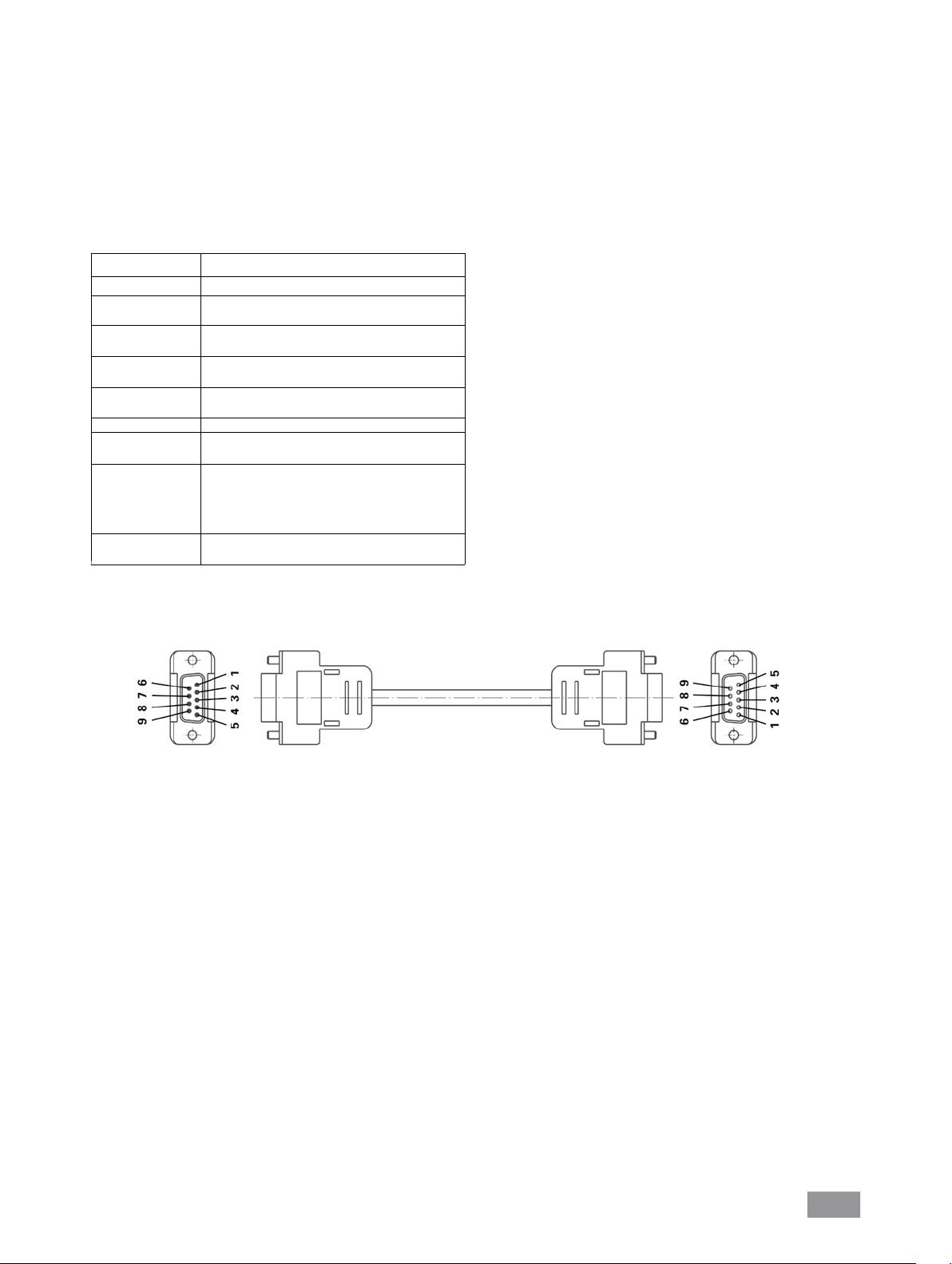
Heizbad
PC 1.1 Kabel (Fig. 24)
Erforderlich zur Verbindung der 9poligen Buchse mit einem PC.
.
Fig. 24
19
Page 20
Inbetriebnahme
Allgemeine Informationen zur Menüführung
Menü wählen
Wählen Sie durch Drehen des Dreh-/ Drückknopfes nach links/ rechts
den gewünschten Menüpunkt aus.
Hinweis: Auf der Displayanzeige sind aktive Menüpunkte schwarz hinterlegt.
Werte editieren
Drücken Sie den Dreh-/ Drückknopf
Drehen Sie den Dreh-/ Drückknopf um den Wert zu ändern (die Größe
der Veränderung ist abhängig von der Drehgeschwindigkeit).
Drücken Sie erneut den Dreh-/ Drückknopf, um den Vorgang zu be-
enden.
Menü verlassen
Drücken Sie die Taste SET.
Aktuelle Werte werden gespeichert.
Das darüberliegende Menü wird angezeigt.
Drücken Sie die Taste ESC.
Aktuelle Werte werden nicht gespeichert.
Das darüberliegende Menü wird angezeigt.
Hinweis: Einige Menüpunkte enthalten keine zu speichernde Werte. Zum
Verlassen des Menüs wählen Sie die Taste SET oder ESC.
Hinweis: Es gibt Änderungen und Ergänzungen dieses Schemas bei einzelnen Menüpunkten.
Displayanzeige während des Prozesses
Für jeden Arbeitsmodus wird eine spezielle Displayanzeige verwendet.
Allen Displayanzeigen sind folgende Eigenschaften gemeinsam:
- Wenn eine Destillation läuft, kann diese Displayanzeige nicht verlassen
werden.
- Wenn keine Destillation läuft, kann durch Drücken der Tasten SET oder
ESC die Displayanzeige verlassen werden. Es erscheint das Hauptmenü.
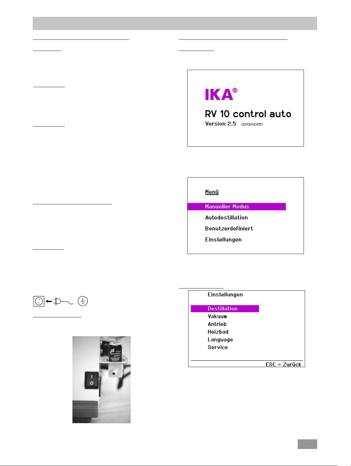
Funktionsbeschreibung (Zustand bei Auslieferung)
Werkseinstellung
Die im Folgenden abgebildeten Werte entsprechen dem Zustand bei
Auslieferung (Displayanzeigen bzw. Sprache der Werkseinstellung ist
englisch).
Während der Anzeige des Startbildschirmes wird der Systemcheck
durchgeführt, Dauer max. 30 Sekunden.
Nach einigen Sekunden erscheint das Hauptmenü.
Fehlermeldung
Wenn in der Displayanzeige eine Fehlermeldung erscheint, quittieren
Sie den Fehler m it der ESC Taste.
Die Fehleranzeige im Fehlerfall wird gelöscht.
Hinweis: Bei schweren Fehlern erscheint eine zusätzliche Anzeige, die
darauf hinweist, dass das Gerät auszuschalten ist und erst nach Beseitigung der Störung wieder eingeschaltet werden darf.
Das Gerät ist nach Einstecken des Netzsteckers betriebsbereit.
Einschalten des Gerätes
Schalten Sie das Gerät auf der rechten Geräteseite mit dem Netzschal-
ter (Fig. 25) ein.
Gerätefunktionen werden aktiviert.
Wählen Sie durch Drehen des Dreh-/ Drückknopfes nach rechts/ links
einen Menüpunkt aus.
Bestätigen Sie die Auswahl durch Drücken des Dreh-/ Drückknopfes.
Menü “Einstellungen“
Vom Menü „Einstellungen“ aus erreichen Sie die im Folgenden aufgeführten Menüpunkte.
Wählen Sie durch Drehen des Dreh-/ Drückknopfes nach rechts/ links
einen Menüpunkt aus.
Bestätigen Sie die Auswahl durch Drücken des Dreh-/ Drückknopfes.
Fig. 25
Hinweis: Beachten Sie, dass auch das Heizbad eingeschaltet sein muss.
20
Page 21
Einstellungen Destillation
Einstellungen Vakuum
Wählen Sie durch Drehen des Dreh-/ Drückknopfes nach rechts/ links
den gewünschten Menüpunkt aus.
Drücken Sie den Dreh-/ Drückknopf.
Drehen Sie den Dreh-/ Drückknopf um den Wert bzw. die Einstellung
zu ändern (die Größe der Veränderung ist abhängig von der Drehgeschwindigkeit).
Drücken Sie erneut den Dreh-/ Drückknopf, um die Änderung zu
beenden.
Taste SET: Sie verlassen das Menü und speichern die Änderungen
Taste ESC: Sie verlassen das Menü, ohne die Änderungen zu speichern.
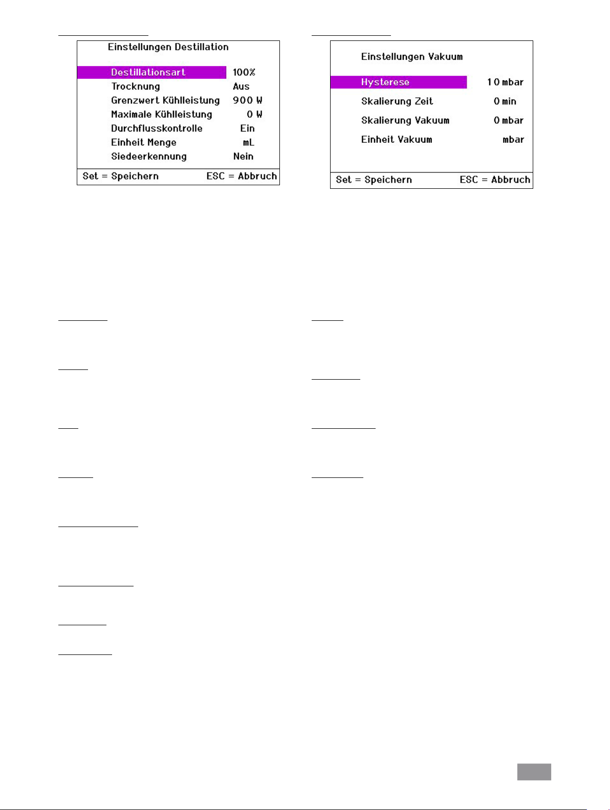
Destillationsart
Sie können zwischen den automatischen Destillationsarten „Volumen“
und „100%“ wählen. Diese Auswahl hat nur Bedeutung für die Autodestillation.
Volumen
Auf der Grundlage der gemessenen Werte Kühlwasserdurchfluss und
Kühlwassertemperaturdifferenz wird für jeden Zeitschritt der Destillation über eine Wärmebilanz die Destillatmenge errechnet. Die Destillation
wird beendet, wenn die vorgegebene Destillatmenge erreicht ist.
100%
Die Destillation wird beendet, wenn die gemessene Kühlwassertemperaturdifferenz einen Schwellwert unterschreitet d.h. sobald ein Lösungsmittel vollständig abdestilliert ist.
Trocknung
Wenn diese Option aktiviert ist, erfolgt keine Überwachung der Kühlwassertemperaturdifferenz z.B. für Trocknungsprozesse pulverförmiger
Medien.
Wählen Sie durch Drehen des Dreh-/ Drückknopfes nach rechts/ links
den gewünschten Menüpunkt aus.
Drücken Sie den Dreh-/ Drückknopf.
Drehen Sie den Dreh-/ Drückknopf um den Wert bzw. die Einstellung
zu ändern (die Größe der Veränderung ist abhängig von der Drehgeschwindigkeit).
Drücken Sie erneut den Dreh-/ Drückknopf, um die Änderung zu be-
enden.
Taste SET: Sie verlassen das Menü und speichern die Änderungen
Taste ESC: Sie verlassen das Menü, ohne die Änderungen zu speichern.
Hysterese
Die Standardeinstellungen für die Hysterese (wie abgebildet) können für
die meisten Anwendungsfälle übernommen werden. Der (Vakuum-) Hysteresenwert beschreibt die Druckdifferenz zwischen Zu- bzw. Wegschalten des Vakuumventils.
Skalierung Zeit
Die Zeitachse des Vakuum-Rotation-Zeit Diagramms wird mit dem angegebenen Wert skaliert. Ist der Wert = 0, wird eine automatische Skalierung der Zeitachse verwendet.
Skalierung Vakuum
Die Vakuumachse des Vakuum-Rotation-Zeit Diagramms wird mit dem
angegebenen Wert skaliert. Ist der Wert = 0, wird eine automatische
Skalierung der Vakuumachse verwendet.
Einheit Vakuum
Sie können zwischen den Vakuumeinheiten mBar, Torr und hPascal wählen.
Grenzwert Kühlleistung
Für den verwendeten Kühler kann eine Grenzleistung angegeben werden, siehe Kapitel “Wissenswertes”. Bei allen Destillationen wird die tatsächliche Leistung berechnet und bei Überschreiten des Grenzwertes die
Destillation mit einer Fehlermeldung abgebrochen.
Maximale Kühlleistung
Es wird die bei der letzten Destillation erreichte maximale Kühlleistung
angezeigt. Dieser Wert ist nur zur Information.
Einheit Menge
Sie können zwischen den Mengeneinheiten mLiter und Gramm wählen.
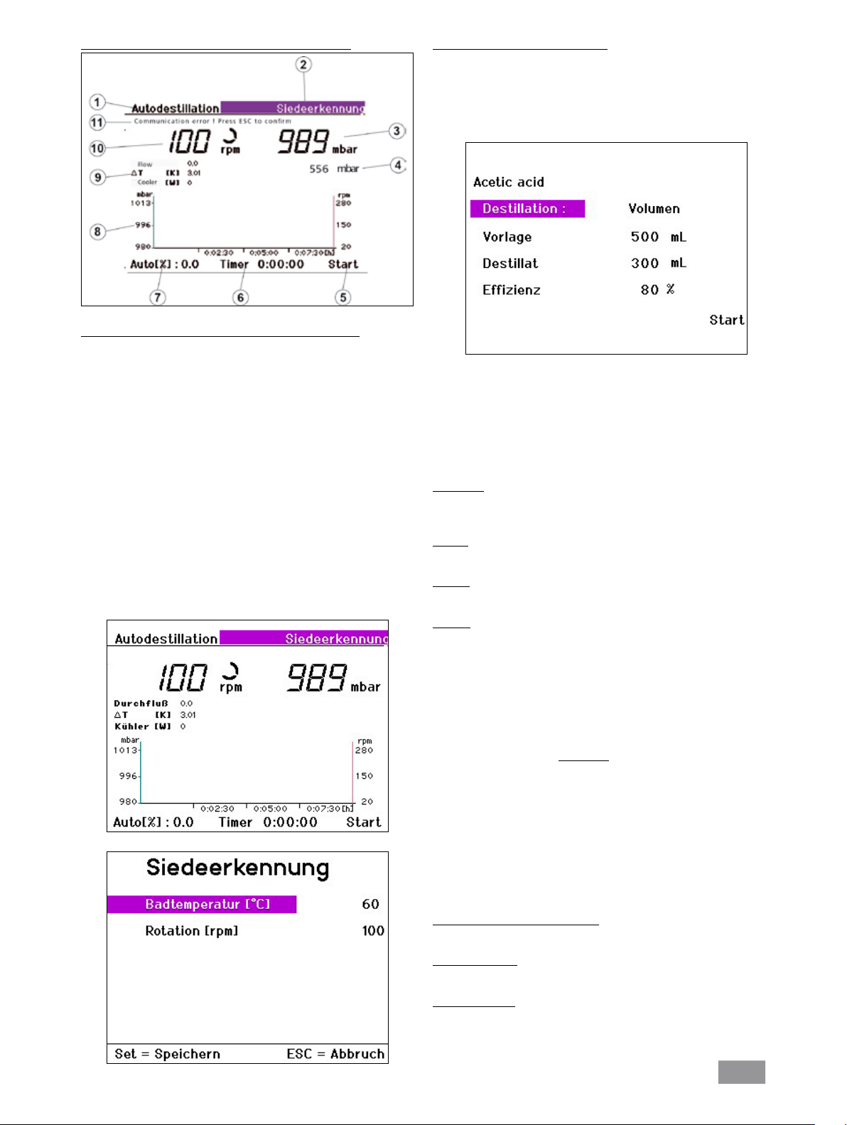
Siedeerkennung
Sie können die Siedeerkennung aktivieren bzw. deaktivieren. Die Siedeerkennung ist nur bei der Destillationsart "100%" möglich!
Mit der Funktion Siedeerkennung wird der Siedepunkt eines Lösemittels
automatisch detektiert.
21
Page 22

Einstellungen Antrieb
Einstellungen Bad
Wählen Sie durch Drehen des Dreh-/ Drückknopfes nach rechts/ links
den gewünschten Menüpunkt aus.
Drücken Sie den Dreh-/ Drückknopf.
Drehen Sie den Dreh-/ Drückknopf um den Wert bzw. die Einstellung
zu ändern (die Größe der Veränderung ist abhängig von der Drehgeschwindigkeit).
Drücken Sie erneut den Dreh-/ Drückknopf, um die Änderung zu
beenden.
Taste SET: Sie verlassen das Menü und speichern die Änderungen
Taste ESC: Sie verlassen das Menü, ohne die Änderungen zu speichern.
Rechts/Links Intervall
Stellen Sie für den Rechts/ Links- Intervall einen bestimmten Wert X ein,
so ändert der Antrieb alle X Sekunden seine Drehrichtung.
Hinweis: Im Intervall- Betrieb ist die max. Drehzahl auf 200 rpm beschränkt.
Timer
Der Timerwert bestimmt, nach welcher Zeit eine manuelle Destillation
beendet wird.
Skalierung Zeit
Die Zeitachse des Vakuum-Rotation-Zeit Diagramms wird mit dem angegebenen Wert skaliert. Ist der Wert = 0, wird eine automatische Skalierung der Zeitachse verwendet.
Skalierung Rotation
Die Rotationsachse des Vakuum-Rotation-Zeit Diagramms wird mit dem
angegebenen Wert skaliert. Ist der Wert = 0, wird eine automatische
Skalierung der Rotationsachse verwendet.
Wählen Sie durch Drehen des Dreh-/ Drückknopfes nach rechts/ links
den gewünschten Menüpunkt aus.
Drücken Sie den Dreh-/ Drückknopf.
Drehen Sie den Dreh-/ Drückknopf um den Wert bzw. die Einstellung
zu ändern (die Größe der Veränderung ist abhängig von der Drehgeschwindigkeit).
Drücken Sie erneut den Dreh-/ Drückknopf, um die Änderung zu
beenden.
Taste SET: Sie verlassen das Menü und speichern die Änderungen
Taste ESC: Sie verlassen das Menü, ohne die Änderungen zu speichern.
Badmedium
Wählen Sie Wasser oder Öl als Medium für das Heizbad.
Sprache
Wählen Sie die gewünschte Sprache durch Drehen des Dreh-/ Drück-
knopfes nach rechts/ links.
Bestätigen Sie die Auswahl mit SET.
22
Page 23
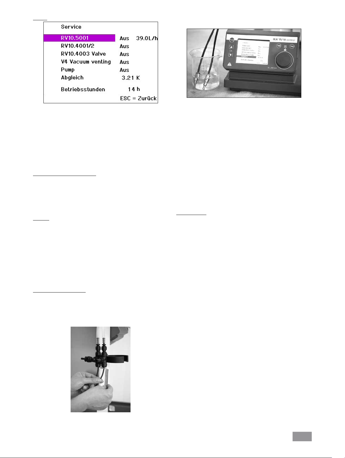
Service
Wählen Sie durch Drehen des Dreh-/ Drückknopfes nach rechts/ links
den gewünschten Menüpunkt aus.
Drücken Sie den Dreh-/ Drückknopf.
Drehen Sie den Dreh-/ Drückknopf um den Wert bzw. die Einstellung
zu ändern (die Größe der Veränderung ist abhängig von der Drehgeschwindigkeit).
Drücken Sie erneut den Dreh-/ Drückknopf, um die Änderung zu
beenden.
Taste ESC: Sie verlassen das Menü. Alle Schaltvorgänge werden zurück-
gesetzt, der Abgleich bleibt erhalten.
Schalten von Ventilen und Pumpe
Im Servicefall verwenden Sie das Servicemenü zur Funktionsprüfung für
das direkte Schalten der im Lieferumfang enthaltenen oder optionalen
Ventile und der Pumpe z. B. RV 10.5001.
Das Ventil RV 10.5001 schaltet den Wasserkreislauf. In dieser Zeile wird
zusätzlich der aktuelle Kühlwasserdurchfluss angezeigt.
Abgleich
Der Menüpunkt „Abgleich“ dient zum Abgleichen der Temperaturmessfühler.
Füllen Sie raumtemperiertes Wasser in ein Becherglas (ca. 500 ml).
Tauchen Sie beide Fühler vollständig in das Wasser, siehe Fig. 27.
Fig. 27
Warten Sie bis sich die Temperaturanzeige im Menü “Service”, Menü-
punkt “Abgleich” stabilisiert hat z.B. 0,2K.
Drücken Sie den Dreh-/ Drückknopf.
Die angezeigte Temperaturdifferenz wird auf Null abgeglichen.
Ein Abgleich ist nur in einem Temperaturbereich zwischen + 0,5 K und
-0,5 K möglich. Sollte die Temperatur außerhalb dieses Bereiches sein, ist
der Temperaturfühler defekt oder nicht korrekt gesteckt. Kontaktieren Sie
bite die Serviceabteilung.
Falls Ihre Kühlwasserversorgung deutlich von den Vorgaben der “Technischen Daten” abweicht und Sie dadurch die Startbedingungen für die
der automatischen Destillation nicht erreichen, ist eventuell ein neuer
Abgleich der Temperaturmessfühler notwendig. Dies kann jedoch im
Modus “Autodestillation” zu einer reduzierten Messgenauigkeit der Destillatmenge führen.
Betriebsstunden
Dieser Wert dient der Information und kann nicht verändert werden.
Die angezeigte Temperaturdifferenz wird auf Null abgeglichen. Die Aktion kann nicht rückgängig gemacht werden.
Ein Abgleich der Temperaturmessfühler muss bei Austausch, Wechsel
bzw. Einbau neuer Temperaturmessfühler durchgeführt werden.
Kontaktieren Sie die Serviceabteilung.
Die im Lieferumfang enthaltenen Temperaturmessfühler sind werkseitig
abgeglichen.
Durchführen des Abgleiches
Aktivieren Sie den Menüpunkt “Abgleich” durch Drehen des Dreh-/
Drückknopfes
Demontieren Sie beide Fühler, indem Sie die Arretierung der Steckver-
bindung durch Zurückziehen des äußeren Ringes lösen und gleichzeitig den Temperaturfühler aus dem Steckverbinder herausziehen, siehe
Fig. 26.
Fig. 26
Zur erneuten Montage stecken Sie den Temperaturmessfühler über
ein anfängliches Widerstandsmoment hinaus, bis auf Anschlag in die
Steckverbindung.
23
Page 24

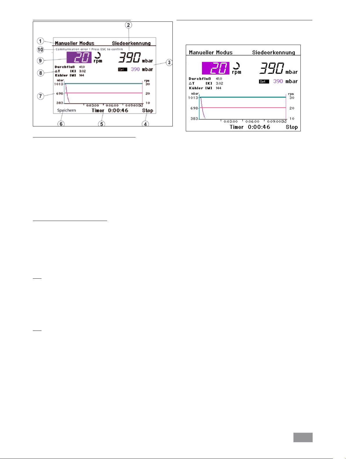
Menü "Manueller Modus ohne Siedeerkennung"
Speichern des Destillationsverlaufs als Prozedur nach beendeter Destillation
Wählen Sie durch Drehen des Dreh-/ Drückknopfes nach links/ rechts
„Speichern“ aus.
Drücken Sie den Dreh-/ Drückknopf, so wird die Bildschirmanzeige
„Prozeduren” angezeigt.
Displayanzeige "Manueller Modus ohne Siedeerkennung"
1. Anzeige des Betriebsmodus
2. Vakuumanzeige (Istwert)
3. Vakuumanzeige (Sollwert)
4. Navigationsfeld „Start/ Stop“ der Destillation
5. Timeranzeige
6. Navigationsfeld für Speichern des Destillationsverlaufs
7. Vakuum-Rotation-Zeit-Diagramm
8. Anzeigen für Durchfluss, Differenztemperatur und Leistung des
Kühlers
9. Navigationsfeld für Rotationsanzeige (Sollwert) und
Rotationssymbol
10. Fehleranzeige im Fehlerfall, sonst Statusanzeige
Einstellen der Rotationsgeschwindigkeit
Drücken Sie den Dreh-/ Drückknopf, um den Sollwert zu ändern.
Drehen Sie den Dreh-/ Drückknopf nach links/ rechts, um den Sollwert
zu verändern. Die Größe der Veränderung ist abhängig von der Drehgeschwindigkeit.
Drücken Sie den Dreh-/ Drückknopf, um den Vorgang zu speichern
und beenden.
Hinweis: Wählen Sie die Drehzahl > 100 rpm ist automatisch der Sanftanlauf aktiviert.
Einstellen des Vakuums
Drücken Sie den Dreh-/ Drückknopf, um den Sollwert zu ändern.
Drehen Sie den Dreh-/ Drückknopf nach links/ rechts, um den Sollwert
zu verändern. Die Größe der Veränderung ist abhängig von der Drehgeschwindigkeit.
Drücken Sie den Dreh-/ Drückknopf, um den Vorgang zu speichern
und beenden.
Wählen Sie eine von zehn Prozeduren durch Drehen des Dreh-/ Drück-
knopfes nach rechts/links. Der Verlauf wird visualisiert.
Drücken Sie SET, um die ausgewählte Prozedur mit der aktuellen Pro-
zedur (die Prozedur, die gerade beendet wurde) zu überschreiben und
das Menü zu verlassen.
Drücken Sie ESC, wird die ausgewählte Prozedur nicht überschrieben.
Hinweis: Den derart gespeicherten Destillationsverlauf können Sie später
im Benutzerdefinierten Modus durch Auswahl der entsprechenden Prozedur wiederholt ausführen.
Start
Wählen Sie durch Drehen des Dreh-/ Drückknopfes nach rechts/ links
„Start“ aus.
Drücken Sie den Dreh-/ Drückknopf und die Destillation beginnt.
Die Displayanzeige wechselt auf „Stop“.
Hinweis: Wurde der Timer gesetzt, beginnt dieser rückwärts zu laufen.
Wurde kein Timer gesetzt, wird die seit dem Start verstrichene Zeit angezeigt.
Stop
Wählen Sie durch Drehen des Dreh-/ Drückknopfes nach links/ rechts
„Stop“ aus.
Drücken Sie den Dreh-/ Drückknopf und die Destillation wird beendet.
Die Displayanzeige wechselt auf „Start“.
24
Page 25
Menü "Manueller Modus mit Siedeerkennung"
Speichern des Destillationsverlaufs als Prozedur nach beendeter Destillation
Wählen Sie durch Drehen des Dreh-/ Drückknopfes nach links/ rechts
„Speichern“ aus.
Drücken Sie den Dreh-/ Drückknopf, so wird die Bildschirmanzeige
„Prozeduren” angezeigt.
Displayanzeige "Manueller Modus mit Siedeerkennung"
1. Anzeige des Betriebsmodus
2. Vakuumanzeige (Istwert)
3. Vakuumanzeige (Sollwert)
4. Navigationsfeld „Start/ Stop“ der Destillation
5. Timeranzeige
6. Navigationsfeld für Speichern des Destillationsverlaufs
7. Vakuum-Rotation-Zeit-Diagramm
8. Anzeigen für Durchfluss, Differenztemperatur und Leistung des
Kühlers
9. Navigationsfeld für Rotationsanzeige (Sollwert) und
Rotationssymbol
10. Fehleranzeige im Fehlerfall, sonst Statusanzeige
Einstellen der Rotationsgeschwindigkeit
Drücken Sie den Dreh-/ Drückknopf, um den Sollwert zu ändern.
Drehen Sie den Dreh-/ Drückknopf nach links/ rechts, um den Sollwert
zu verändern. Die Größe der Veränderung ist abhängig von der Drehgeschwindigkeit.
Drücken Sie den Dreh-/ Drückknopf, um den Vorgang zu speichern
und beenden.
Hinweis: Wählen Sie die Drehzahl > 100 rpm ist automatisch der Sanftanlauf aktiviert.
Start
Wählen Sie durch Drehen des Dreh-/ Drückknopfes nach rechts/ links
„Start“ aus.
Drücken Sie den Dreh-/ Drückknopf und die Destillation beginnt.
Die Displayanzeige wechselt auf „Stop“.
Hinweis: Wurde der Timer gesetzt, beginnt dieser rückwärts zu laufen.
Wurde kein Timer gesetzt, wird die seit dem Start verstrichene Zeit angezeigt.
Wählen Sie eine von zehn Prozeduren durch Drehen des Dreh-/ Drück-
knopfes nach rechts/links. Der Verlauf wird visualisiert.
Drücken Sie SET, um die ausgewählte Prozedur mit der aktuellen Pro-
zedur (die Prozedur, die gerade beendet wurde) zu überschreiben und
das Menü zu verlassen.
Drücken Sie ESC, wird die ausgewählte Prozedur nicht überschrieben.
Hinweis: Den derart gespeicherten Destillationsverlauf können Sie später
im Benutzerdefinierten Modus durch Auswahl der entsprechenden Prozedur wiederholt ausführen.
Stop
Wählen Sie durch Drehen des Dreh-/ Drückknopfes nach links/ rechts
„Stop“ aus.
Drücken Sie den Dreh-/ Drückknopf und die Destillation wird beendet.
Die Displayanzeige wechselt auf „Start“.
25
Page 26
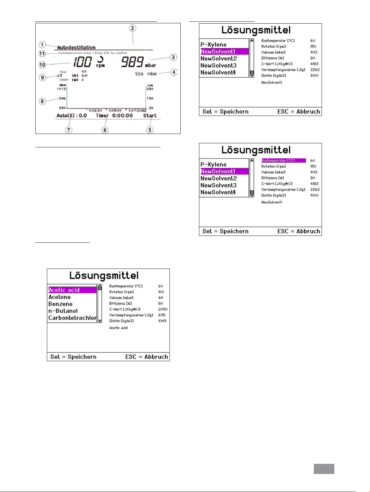
Menü "Modus Autodestillation ohne Siedeerkennung"
Displayanzeige “Modus Autodestillation ohne Siedeerkennung”
1. Anzeige des Betriebsmodus
2. Navigationsfeld Lösungsmittel
3. Vakuumanzeige (Istwert)
4. Vakuumanzeige (Sollwert)
5. Navigationsfeld „Start/ Stop“ der Destillation
6. Timeranzeige
7. Fortschrittsanzeige der Destillation
(% der geforderten Destillatmenge)
8. Vakuum-Rotation-Zeit-Diagramm
9. Anzeigen für Durchfluss, Differenztemperatur und Leistung des
Kühlers
10. Rotationsanzeige (Sollwert) und Rotationssymbol
11. Fehleranzeige im Fehlerfall, sonst Statusanzeige
Benutzerdefinierte Lösungsmittel
Wählen Sie in der Displayanzeige für Lösungsmittel den Bereich NewSolvent1 ... NewSolvent5.
Wählen Sie eines dieser Lösungsmittel aus und drücken Sie den Dreh-/
Drückknopf.
Auswahl Lösemittel ändern
Wählen Sie durch Drehen des Dreh-/ Drückknopfes nach links/ rechts
das Navigationsfeld „Lösemittel“ aus.
Drücken Sie den Dreh-/ Drückknopfes, so erscheint auf dem Display
die Auswahl für Lösungsmittel.
Wählen Sie durch Drehen des Dreh-/ Drückknopfes nach links/ rechts
ein Lösungsmittel.
Drücken Sie die Taste SET.
Das gewählte Lösungsmittel wird für die folgende Destillation ver-
wendet.
Hinweis: Für jedes Lösungsmittel werden die Parameter angezeigt. Diese
Parameter können Sie nur für die von Ihnen definierten Lösungsmittel
UserSolvent1 ... UserSolvent5 ändern. Dies wird im folgenden Abschnitt
beschrieben.
Sie können jetzt alle dargestellten Parameter des Lösungsmittels verändern.
Wählen Sie durch Drehen des Dreh-/ Drückknopfes nach links/ rechts
den zu ändernden Parameter aus.
Drücken Sie den Dreh-/ Drückknopf.
Ändern Sie den gewählten Parameter durch Drehen des Dreh-/ Drück-
knopfes nach links/ rechts.
Drücken Sie den Dreh-/ Drückknopf.
Speichern Sie alle Werte mit der Taste SET.
NewSolvent1 ist als aktuelles Lösungsmittel ausgewählt.
Hinweis: Eine Rückkehr in die Auswahlbox ist nicht möglich.
26
Page 27
Menü "Modus Autodestillation mit Siedeerkennung"
Displayanzeige “Modus Autodestillation mit Siedeerkennung”
1. Anzeige des Betriebsmodus
2. Navigationsfeld Lösungsmittel
3. Vakuumanzeige (Istwert)
4. Vakuumanzeige (Sollwert)
5. Navigationsfeld „Start/ Stop“ der Destillation
6. Timeranzeige
7. Fortschrittsanzeige der Destillation
(% der geforderten Destillatmenge)
8. Vakuum-Rotation-Zeit-Diagramm
9. Anzeigen für Durchfluss, Differenztemperatur und Leistung des
Kühlers
10. Rotationsanzeige (Sollwert) und Rotationssymbol
11. Fehleranzeige im Fehlerfall, sonst Statusanzeige
Beginn der automatischen Destillation
Drücken Sie den Dreh-/Drückknopf auf dem Feld „Start“ bzw. „Weiter“. Wenn die Optionen „100% Destillation“ oder „Trocknung“ aktiviert
sind, startet die Destillation, wenn die notwendigen Bedingungen erfüllt
sind.
Bei der Destillationsart „Volumen“ werden in einem weiteren Bildschirm
zusätzliche Destillationparameter eingegeben.
Wählen Sie durch Drehen des Dreh-/ Drückknopfes nach links/ rechts
den gewünschten Menüpunkt aus.
Drücken Sie den Dreh-/ Drückknopf.
Drehen Sie den Dreh-/ Drückknopf um den Wert bzw. die Einstellung
zu ändern (die Größe der Veränderung ist abhängig von der Drehgeschwindigkeit).
Drücken Sie erneut den Dreh-/ Drückknopf, um die Änderung zu
beenden.
Destillation
Die unter Einstellungen/Destillation gewählte Destillationsart wird hier
angezeigt und kann nicht mehr geändert werden.
Hinweis: Volumendestillation ist nicht möglich da in diesem Modus das
Lösemittel bekannt sein muss.
In diesem Modus kann statt einer Auswahl des Lösungsmittels die Bad
temperatur und die Drehzahl des Rotationsantriebs über das Navigationsfeld "Siedeerkennung" eingestellt werden.
Vorlage
Geben Sie die Menge ein, die sich im Vorlagekolben befindet.
Destillat
Geben Sie die Menge ein, die abdestilliert werden soll.
Effizienz
Für die Bilanzierung ist die Eingabe einer exakten thermischen Effizienz
notwendig.
Die Effizienz ist von der Gesamtheit der Destillationsbedingungen abhängig und zunächst ein Schätzwert. Deshalb dient der erste Destillationslauf zur Kalibrierung. Nach dem Ende der Destillation ermitteln Sie die
tatsächlich abdestillierte Menge und berechnen die tatsächliche Effizienz
nach der Formel :
m
ηth . m
ηP =
(calc)
(gem)
ηP tatsächlicher Wirkungsgrad
η
geschätzter Wirkungsgrad
th
m
gemessene Destillatmenge
(gem)
m
vorgegebene (berechnete) Destillatmenge
(calc)
Für die folgenden Destillationen geben Sie die so ermittelte tatsächliche Effizienz ein und die folgenden Destillationen werden bei gleichen
Destillations- und Standortbedingungen automatisch mit ausreichender
Genauigkeit durchgeführt.
Ende der automatischen Destillation
Die automatische Destillation wird nach folgenden Kriterien beendet:
Volumengesteuert
Die vorgegebene Destillatmenge wurde bilanziert.
100% Destillation
Die gemessene Kühlwassertemperaturdifferenz unterschreitet einen Sollwert, das Lösungsmittel ist vollständig verdampft.
Zusätzlich kann die Destillation auch manuell beendet werden:
Drücken Sie den Dreh-/ Drückknopf auf dem Anzeigefeld „Stop”.
27
Page 28
Menü „Benutzerdefinierte Destillation“
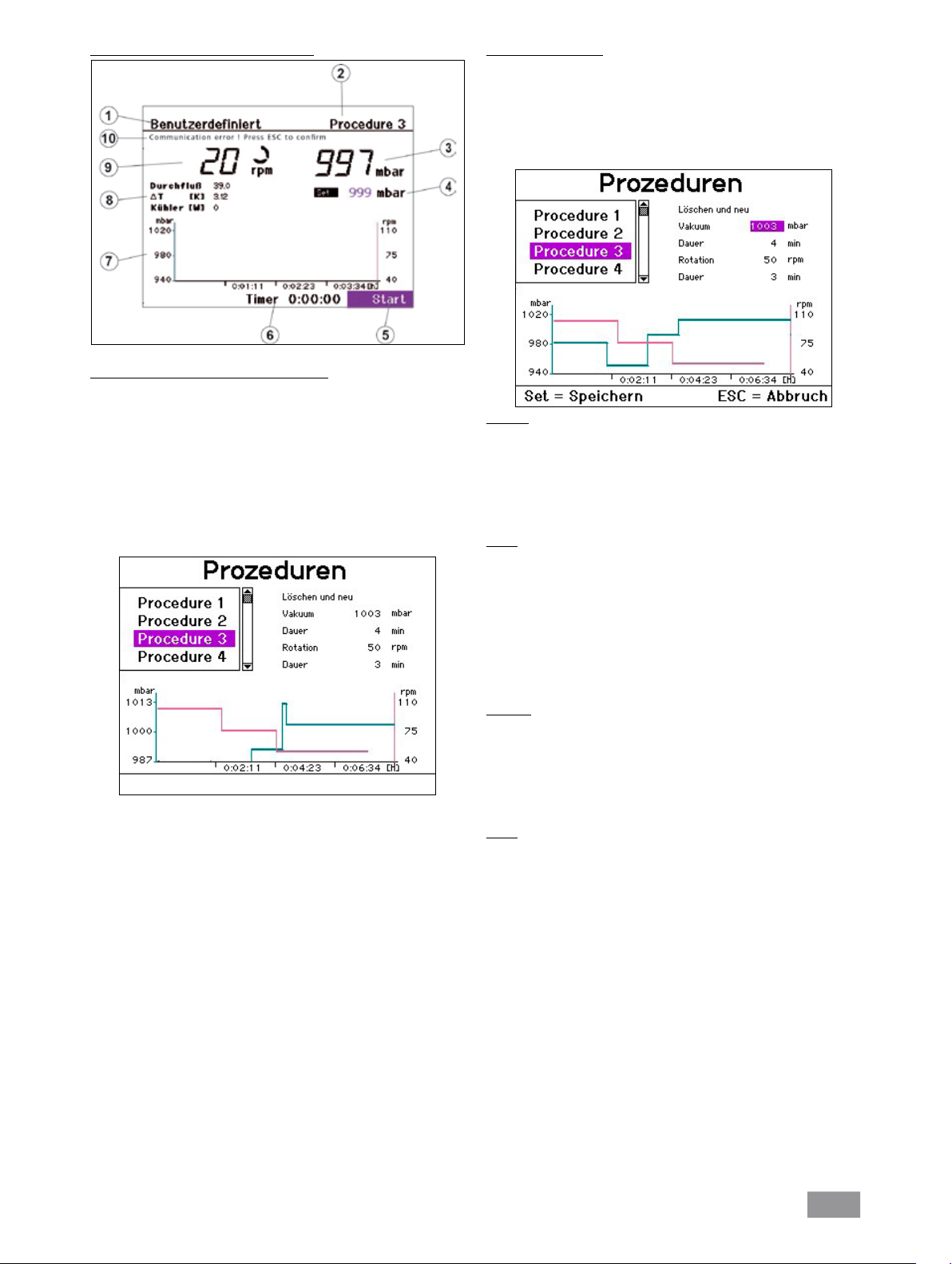
Displayanzeige “Benutzerdefinierte Destillaton”
1. Anzeige des Betriebsmodus
2. Navigationsfeld für Destillationsprozedur
3. Vakuumanzeige (Istwert)
4. Vakuumanzeige (Sollwert)
5. Navigationsfeld „Start/ Stop“ der Destillation
6. Timeranzeige
7. Vakuum-Rotation--Zeit-Diagramm
8. Anzeigen für Durchfluss, Differenztemperatur und
Leistung des Kühlers
9. Rotationsanzeige (Sollwert) und Rotationssymbol
10. Fehleranzeige im Fehlerfall, sonst Statusanzeige/
Ändern einer Prozedur
Wählen Sie die zu ändernde Prozedur aus und drücken Sie den Dreh-/
Drückknopf. Das Anzeigefeld „Löschen und neu“ wird aktiviert.
Wenn Sie den Dreh-/Drückknopf auf dem Anzeigefeld „Löschen und
neu“ drücken, wird die Prozedur gelöscht.
Sie können jetzt neue Prozedurschritte für Vakuum und Rotation hinzufügen.
Vakuum
Wählen Sie durch Drehen des Dreh-/ Drückknopfes nach links/rechts
in der Displayanzeige „Vakuum“.
Drücken Sie den Dreh-/ Drückknopf.
Geben Sie einen Wert ein durch Drehen des Dreh-/ Drückknopfes nach
links/ rechts.
Drücken Sie den Dreh-/ Drückknopf.
Dauer
Wählen Sie durch Drehen des Dreh-/ Drückknopfes nach links/rechts
in der Displayanzeige „Dauer“.
Drücken Sie den Dreh-/ Drückknopf.
Geben Sie einen Wert ein durch durch Drehen des Dreh-/ Drückknop-
fes nach links/ rechts.
Drücken Sie den Dreh-/ Drückknopf. Ein neuer Prozedurschritt mit
dem Wertepaar Vakuum-Dauer wird definiert und der Prozedur hinzugefügt. Das Diagramm wird aktualisiert.
Wählen Sie durch Drehen des Dreh-/ Drückknopfes nach links/ rechts
„Procedure“ aus.
Drücken Sie den Dreh-/ Drückknopf.
Es erscheint die Displayanzeige “Prozeduren”.
Wählen Sie durch Drehen des Dreh-/ Drückknopfes nach links/ rechts
eine Prozedur aus.
Drücken Sie die Taste SET.
Die gewählte Prozedur wird für die folgende Destillation verwendet.
Hinweis: Für jede Prozedur wird das Vakuum-Rotation-Zeit-Diagramm
angezeigt. Die Parameter können Sie für jede Prozedur ändern. Dies wird
im folgenden Abschnitt beschrieben. Außerdem können Sie den Verlauf
einer manuellen Destillation als Prozedur speichern, siehe Abschnitt
„Manueller Modus“.
Rotation
Wählen Sie durch Drehen des Dreh-/ Drückknopfes nach links/rechts
in der Displayanzeige „Rotation“.
Drücken Sie den Dreh-/ Drückknopf.
Geben Sie einen Wert ein durch durch Drehen des Dreh-/ Drück-knop-
fes nach links/ rechts.
Drücken Sie den Dreh-/ Drückknopf.
Dauer
Wählen Sie durch Drehen des Dreh-/ Drückknopfes nach links/rechts
in der Displayanzeige „Dauer“.
Drücken Sie den Dreh-/ Drückknopf.
Geben Sie einen Wert ein durch durch Drehen des Dreh-/ Drückknop-
fes nach links/ rechts.
Drücken Sie den Dreh-/ Drückknopf . Ein neuer Prozedurschritt mit
dem Wertepaar Rotation-Dauer wird definiert und der Prozedur hinzugefügt. Das Diagramm wird aktualisiert.
Die Schritte Vakuum, Dauer und Rotation,Dauer können maximal zwanzigmal wiederholt werden.
Taste SET: Das Menü wird verlassen. Die neu erstellte Prozedur wird gespeichert und als die aktuelle Prozedur ausgewählt.
Taste ESC: Das Menü wird verlassen. Alle Änderungen werden rückgängig gemacht
28
Page 29

Beenden der benutzerdefinierten Destillation
Die benutzerdefinierte Destillation wird nach Ablauf aller Prozedurschritte der aktuellen Prozedur automatisch beendet. Zusätzlich ist auch das
manuelle Beenden durch Drücken des Dreh-/Drückknopfes auf dem Anzeigefeld „Stop“ möglich
Stand-by Betrieb
Drücken Sie die Taste „Power“.
Das Gerät wird in Stand-by gesetzt.
Drücken Sie erneut die Taste „Power“
Es erscheint das Hauptmenü und das Gerät ist wieder betriebsbereit
29
Page 30
Menüführung
Prozedur 1
Prozedur 2
Prozedur 3
Prozedur 4
Prozedur 5
Prozedur 6
Prozedur 7
Prozedur 8
Prozedur 9
Prozedur 10
Destillationsart
Trocknung
Grenzwert Kühlleistung
Maximale Kühlleistung
Maximale Kühlleistung
Durchflusskontrolle
Einheit Menge
Siedeerkennung
Einheit Vakuum
Skalierung Zeit
Skalierung Rotation
Aceton
Wasser
Toluon
N-Pantenol
Benzol
Heizbadtemperatur
Rotation
Temperatur Heizbad
Rotation
UserSolvent 1
UserSolvent 2
UserSolvent 3
UserSolvent 4
Vakuum
Wirkungsgrad
C-Wert
UserSolvent 5
Verdampfungsenthalpie
Dichte
Prozedur löschen
Vakuum
Dauer
Rotation
Dauer
Bestätigen
Hysterese
Skalierung Zeit
Skalierung Vakuum
Rechts/Links Intervall
Timer
Wasser
Öl
Prozedur 1
Prozedur 2
Prozedur 3
Prozedur 4
Prozedur 5
Prozedur 6
Prozedur 7
Prozedur 8
Prozedur 9
Anzeige Vakuum-Rotation-Zeit-Diagramm
Start/Stop, weitere Parameter
Anzeige Fehler
Anzeige Durchfluss, Differenztemperatur, Leistung Kühler
Prozedur 10
Badmedium
Destillation
Vakuum
Antrieb
Heizbad
English
Deutsch
Français
RV10.5001
RV10.4001/2
Language
Service
Español
中文
Polski
日本語
RV10.4003 Ventil
V4 Vakuumentlüftung
Pumpe
Abgleich
Betriebsstunden
Vorlagemenge
Destillatmenge
Navigationsfeld Lösemittel / Siedeerkennung
Start/Stop, weitere Parameter
Wirkungsgrad
Sollwert Rotation
Sollwert und Istwert Vakuum
Anzeige Forschritt der Destillation
Anzeige Fehler
Anzeige Durchfluss, Differenztemperatur, Leistung Kühler
Anzeige Vakuum-Rotation-Zeit-Diagramm
Anzeige Timer
Navigationsfeld Destillationsprozedur
Siederkennung nein
Siederkennung ja
Start/Stop
Sollwert Rotation
Speichern, Navigation Prozeduren
Sollwert und Istwert Vakuum
Anzeige Timer
Siedeerkennung ein?
Anzeige Fehler
Anzeige Durchfluss, Differenztemperatur, Leistung Kühler
Anzeige Vakuum-Rotation-Zeit-Diagramm
Sollwert Rotation
Sollwert und Istwert Vakuum
Anzeige Timer
Hauptmenü
Modus manuell
Modus Autodestillation
Modus benutzdefiniert
Startbildschirm
Einstellungen
30
Page 31

Einstellen des unteren Endanschlages
Achtung! In Abhängigkeit von Kolbengröße, Einstellwinkel des Rotati-
onsantriebes sowie Heizbad- und Liftposition kann der Verdampferkolben am Heizbad aufstehen. Glasbruchgefahr!
Begrenzen Sie mit dem variablen Endanschlag die untere Liftposition.
Im manuellen Modus ist eine beliebige Positionierung des Liftes mittels
der Tasten “ ” und “ ” möglich. Es erfolgt keine automatische Abschaltung bei Kollision.
Drücken Sie die Taste " " bis der Lift die gewünschte Position erreicht.
Hinweis: Der Verdampferkolben sollte zu 2/3 im Heizbad eintauchen.
Zur Verstellung des Anschlagelementes (Q) drücken Sie den zentralen
Knopf (R) an der Liftvorderseite (Fig. 18).
Schieben Sie den Anschlag (Q) in die gewünschte Position (Fig. 19).
Drücken Sie die Taste " " bis der Lift den oberen Endanschlag erreicht.
Hinweis: Der Weg ist von 0 – 6 cm begrenzt.
R
Q
Befüllen des Verdampferkolbens
Vor Befüllen des Verdampferkolbens wird mittels Vakuumsteuerung die
Glasapparatur auf Soll-Druck geregelt.
Befüllen Sie nun über die Nachspeiseleitung den Verdampferkolbens,
siehe Fig. 30.
Aufgrund des vorhandenen Unterdrucks wird das Lösemittel in den
Verdampferkolben gesaugt. Dadurch können Sie die Lösemittelverluste durch Absaugen so gering wie möglich halten.
Sie können auch vor Anlegen des Vakuums den Verdampferkolben
manuell befüllen. Der Verdampferkolben sollte nicht über die Hälfte
seines Volumens gefüllt werden.
Hinweis: Achtung! Maximal zulässige Zuladung (Verdampferkolben
und Inhalt) beträgt 3 kg.
Fig. 28
Fig. 29
Überprüfen Sie die Funktion der Endabschaltung:
Fahren Sie den Lift durch dauerhaftes Drücken der Taste " " nach
unten.
Der Antrieb stellt bei Erreichen der eingestellten unteren Endlage au-
tomatisch ab.
Fahren Sie den Antrieb wieder in die obere Position.
Zur Aktivierung der Lift Sicherheitsanhebung nach längerem Stillstand,
fahren Sie den Lift vor Destillationsbeginn mehrmals motorisch in die
unterste bzw. oberste Endlage. (siehe Kapitel Sicherheitshinweise -
Sicherheitsanhebung)!
Aufstellung Heizbad
Beachten Sie auch die Betriebsanleitung des Heizbades IKA® HB 10!
Fahren Sie den Lift in die untere Position und überprüfen Sie die Heiz-
badposition zur Lage des Verdampferkolbens. Bei Verwendung von
größeren Verdampferkolben (2 bzw. 3 Liter) bzw. je nach eingestelltem Winkel des Rotationsantriebs können Sie das Heizbad um 50 mm
nach rechts verschieben.
Befüllen Sie das Heizbad mit dem Temperiermedium bis der Verdamp-
ferkolben zu 2/3 seines Volumens mit Temperiermedium umgeben ist.
Schalten Sie den Rotationsantrieb ein und erhöhen Sie die Drehzahl
langsam.
Hinweis: Vermeiden Sie Wellenbildung.
Schalten Sie das Heizbad am Hauptschalter ein.
Hinweis: Vermeiden Sie Spannungen am Glas durch unterschiedliche
Verdampferkolben- und Heizbadtemperatur beim Absenken des Verdampferkolbens in das Heizbad!
Hinweis: Verwenden Sie anderes Zubehör als das originale Zubehör von
IKA®, ist der Verschiebeweg des Heizbades von 50 mm eventuell nicht
mehr ausreichend, insbesondere beim Einsatz von 3 l - Verdampferkolben und Schaumbremse.
Verwenden Sie die IKA® Anbauplatte RV 10.3000, um den Verschiebeweg des Heizbades um 150 mm zu erweitern.
Fig. 30
31
Page 32

Wartung und Reinigung
Das Gerät arbeitet wartungsfrei. Es unterliegt lediglich der natürlichen
Alterung der Bauteile und deren statistischer Ausfallrate.
Die Dichtung am Glaskühler sollte in regelmäßigen Abständen kontrolliert und gegebenenfalls ausgetauscht werden.
Ziehen Sie zum Reinigen den Netzstecker.
Für die Reinigung des Gerätes ist ausschließlich Wasser mit einem tensidhaltigen Waschmittelzusatz oder bei stärkerer Verschmutzung Isopropylalkohol zu verwenden.
Ersatzteilbestellung
Bei Ersatzteilbestellungen geben Sie bitte Folgendes an:
- Gerätetyp,
- Fabrikationsnummer des Gerätes, siehe Typenschild,
- Positionsnummer und Bezeichnung des Ersatzteiles, siehe Ersatzteilbild
und -liste unter www.ika.com.
Zubehör
Reparaturfall
Im Reparaturfall muss das Gerät gereinigt und frei von gesundheitsgefährdenden Stoffen sein. Verwenden Sie hierzu das Formular “Unbe-
denklichkeitsbescheinigung“, Download-Ausdruck des Formulares
auf der IKA® Website www.ika.com.
Senden Sie das Gerät in der Originalverpackung zurück. Lagerverpackungen sind für den Rückversand nicht ausreichend. Verwenden Sie zusätzlich eine geeignete Transportverpackung.
Sicherheitsanhebung
Die Sicherheitsanhebung muss täglich vor dem Betrieb überprüft werden!
Bei längerem Stillstand (ca. vier Wochen) fahren Sie den Lift vor Destillationsbeginn mehrmals motorisch in die unterste bzw. oberste Endlage.
(siehe Kapitel Sicherheitshinweise - Sicherheitsanhebung)! Funktioniert
die Sicherheitsanhebung nicht mehr, kontaktieren Sie sich bitte die IKA®
Serviceabteilung.
RV 10.1 NS 29/32 Glassatz vertikal (1)
RV 10.10 NS 29/32 Glassatz vertikal ,beschichtet (1)
RV 10.2 NS 29/32 Glasatz diagonal (2)
RV 10.20 NS 29/32 Glasatz diagonal, beschichtet (2)
RV 10.700 NS 29/42 Glassatz vertikal (1)
RV 10.710 NS 29/42 Glassatz vertikal ,beschichtet (1)
RV 10.800 NS 29/42 Glassatz diagonal (2)
RV 10.810 NS 29/42 Glassatz diagonal, beschichtet (2)
RV 10.900 NS 24/40 Glassatz vertikal (1)
RV 10.910 NS 24/40 Glassatz vertikal ,beschichtet (1)
RV 10.1000 NS 24/40 Glassatz diagonal (2)
RV 10.1010 NS 24/40 Glassatz diagonal, beschichtet (2)
RV 10.3 Vertikal-Intensivkühler mit Verteilerstück (1)
RV 10.30
RV 10.4 Trockeneiskühler (2)
RV 10.40 Trockeneiskühler, beschichtet (2)
RV 10.5 Rückflussdestillation mit Vertikalkühler (o. Abb.)
RV 10.50
RV 10.6 Rückflussdestillation mit Intensivkühler (3)
RV 10.60 Rückflussdestillation mit Intensivkühler, beschichtet (3)
HB 10.1 Schutzschild (Heizbad HB 10) (1)
HB 10.2 Schutzhaube (Heizbad HB 10) (2)
RV 10.70 NS 29/32 Dampfdurchführungsrohr
RV 10.71 NS 24/29 Dampfdurchführungsrohr
RV 10.72 NS 29/42 Dampfdurchführungsrohr
RV 10.73 NS 24/40 Dampfdurchführungsrohr
RV 10.74 NS 29/32 Dampfdurchführungsrohr, kurz,
für Rückflussdestillation
RV 10.75 NS 24/29 Dampfdurchführungsrohr, kurz,
für Rückflussdestillation
RV 10.76 NS 29/42 Dampfdurchführungsrohr, kurz,
für Rückflussdestillation
RV 10.77 NS 24/40 Dampfdurchführungsrohr, kurz,
für Rückflussdestillation
Vertikal-Intensivkühler mit Verteilerstück, beschichtet (1)
Rückflussdestillation mit Vertikalkühler, beschichtet (o. Abb.)
32
Page 33

RV 10.80 NS 29/32 Verdampferkolben 50 ml
RV 10.81 NS 29/32 Verdampferkolben 100 ml
RV 10.82 NS 29/32 Verdampferkolben 250 ml
RV 10.83 NS 29/32 Verdampferkolben 500 ml
RV 10.84 NS 29/32 Verdampferkolben 1000 ml
RV 10.85 NS 29/32 Verdampferkolben 2000 ml
RV 10.86 NS 29/32 Verdampferkolben 3000 ml
RV 10.90 NS 24/32 Verdampferkolben 50 ml
RV 10.91 NS 24/32 Verdampferkolben 100 ml
RV 10.92 NS 24/32 Verdampferkolben 250 ml
RV 10.93 NS 24/32 Verdampferkolben 500 ml
RV 10.94 NS 24/32 Verdampferkolben 1000 ml
RV 10.95 NS 24/32 Verdampferkolben 2000 ml
RV 10.96 NS 24/32 Verdampferkolben 3000 ml
RV 10.97 NS 24/40 Verdampferkolben 1000 ml
RV 10.2001 NS 29/42 Verdampferkolben 50 ml
RV 10.2002 NS 29/42 Verdampferkolben 100 ml
RV 10.2003 NS 29/42 Verdampferkolben 250 ml
RV 10.2004 NS 29/42 Verdampferkolben 500 ml
RV 10.87 NS 29/42 Verdampferkolben 1000 ml
RV 10.2005 NS 29/42 Verdampferkolben 2000 ml
RV 10.2006 NS 29/42 Verdampferkolben 3000 ml
RV 10.2007 NS 24/40 Verdampferkolben 50 ml
RV 10.2008 NS 24/40 Verdampferkolben 100 ml
RV 10.2009 NS 24/40 Verdampferkolben 250 ml
RV 10.2010 NS 24/40 Verdampferkolben 500 ml
RV 10.2011 NS 24/40 Verdampferkolben 1000 ml
RV 10.2012 NS 24/40 Verdampferkolben 2000 ml
RV 10.2013 NS 24/40 Verdampferkolben 3000 ml
RV 10.100 KS 35/20 Auffangkolben 100 ml
RV 10.101 KS 35/20 Auffangkolben 250 ml
RV 10.102 KS 35/20 Auffangkolben 500 ml
RV 10.103 KS 35/20 Auffangkolben 1000 ml
RV 10.104 KS 35/20 Auffangkolben 2000 ml
RV 10.105 KS 35/20 Auffangkolben 3000 ml
RV 10.200 KS 35/20 Auffangkolben beschichtet 100 ml
RV 10.201 KS 35/20 Auffangkolben beschichtet 250 m
RV 10.202 KS 35/20 Auffangkolben beschichtet 500 ml
RV 10.203 KS 35/20 Auffangkolben beschichtet 1000 ml
RV 10.204 KS 35/20 Auffangkolben beschichtet 2000 ml
RV 10.205 KS 35/20 Auffangkolben beschichtet 3000 ml
RV 10.300 NS 29/32 Pulverkolben 500 ml
RV 10.301 NS 29/32 Pulverkolben 1000 ml
RV 10.302 NS 29/32 Pulverkolben 2000 ml
RV 10.303 NS 24/29 Pulverkolben 500 ml
RV 10.304 NS 24/29 Pulverkolben 1000 ml
RV 10.305 NS 24/29 Pulverkolben 2000 ml
RV 10.2014 NS 29/32 Pulverkolben 500 ml
RV 10.2015 NS 29/32 Pulverkolben 1000 ml
RV 10.2016 NS 29/32 Pulverkolben 2000 ml
RV 10.217 NS 24/40 Pulverkolben 500 ml
RV 10.218 NS 24/40 Pulverkolben 1000 ml
RV 10.219 NS 24/40 Pulverkolben 2000 ml
RV 10.400 NS 29/32 Verdampfungszylinder 500 ml
RV 10.401 NS 29/32 Verdampfungszylinder 1500 ml
33
Page 34

RV 10.402 NS 24/29 Verdampfungszylinder 500 ml
RV 10.403 NS 24/29 Verdampfungszylinder 1500 ml
RV 10.2020 NS 29/42 Verdampfungszylinder 500 ml
RV 10.2021 NS 29/42 Verdampfungszylinder 1500 ml
RV 10.2022 NS 24/40 Verdampfungszylinder 500 ml
RV 10.2023 NS 24/40 Verdampfungszylinder 1500 ml
RV 10.500 NS 29/32 Schaumbremse
RV 10.501 NS 24/29 Schaumbremse
RV 10.2024 NS 29/42 Schaumbremse
RV 10.2025 NS 24/40 Schaumbremse
RV 10.600 NS 29/32 Destillationsspinne mit 6 Destillierhülsen
RV 10.601 NS 29/32 Destillationsspinne mit 12 Destillierhülsen
RV 10.602 NS 29/32 Destillationsspinne mit 20 Destillierhülsen
RV 10.603 NS 24/29 Destillationsspinne mit 6 Destillierhülsen
RV 10.604 NS 24/29 Destillationsspinne mit 12 Destillierhülsen
RV 10.605 NS 24/29 Destillationsspinne mit 20 Destillierhülsen
RV 10.2026 NS 29/42 Destillationsspinne mit 6 Destillierhülsen
RV 10.2027 NS 29/42 Destillationsspinne mit 12 Destillierhülsen
RV 10.2028 NS 29/42 Destillationsspinne mit 20 Destillierhülsen
RV 10.2029 NS 24/40 Destillationsspinne mit 6 Destillierhülsen
RV 10.2030 NS 24/40 Destillationsspinne mit 12 Destillierhülsen
RV 10.2031 NS 24/40 Destillationsspinne mit 20 Destillierhülsen
RV 10.610 Destillierhülse 20 ml
RV 10.606 NS 29/32 Destillationsspinne mit 5 Flaschen 50 ml
RV 10.607 NS 29/32 Destillationsspinne mit 5 Flaschen 100 ml
RV 10.608 NS 24/29 Destillationsspinne mit 5 Flaschen 50 ml
RV 10.609 NS 24/29 Destillationsspinne mit 5 Flaschen 100 ml
RV 10.2032 NS 29/42 Destillationsspinne mit 5 Flaschen 50 ml
RV 10.2033 NS 29/42 Destillationsspinne mit 5 Flaschen 100 ml
RV 10.2034 NS 24/40 Destillationsspinne mit 5 Flaschen 50 ml
RV 10.2035 NS 24/40 Destillationsspinne mit 5 Flaschen 100 ml
RV 10.3000 Anbauplatte
RV 10.4001 Magnetventil Hausvakuum (1)
RV 10.4002 Magnetventil Laborvakuum (2)
RV 10.4003 Pumpensteuerung inkl. Magnetventil (3)
RV 10.5001 Drosselventil Wasser (4), nur für an Betrieb an
Wasserleitung!
RV 10.5002 Filter (5)
RV 10.5003 Druckregelventil (6)
RV 10.8001 Dichtung, PTFE compound
PC 1.1 Kabel
Labworldsoft
®
34
Page 35

Fehlercodes
Eine Störung während des Betriebes wird durch eine Fehlermeldung im Display angezeigt.
Nach Anzeigen einer schwerwiegenden Fehlermeldung fährt der Lift in die obere Endlage und die Gerätebedienung ist gesperrt. Der Lift lässt sich
weiterbedienen.
Gehen Sie dann wie folgt vor:
Gerät am Geräteschalter ausschalten
Korrekturmaßnahmen treffen
Gerät erneut starten
Fehler- Folge Ursache Korrektur
Kommunikations- Die Destillation wird im Modus „Auto- IR-Schnittstelle blockiert -Bestätigen Sie mit ESC
fehler Bad destillation“ abgebrochen Heizbad ausgeschaltet -Heizbad einschalten
IR-Schnittstelle prüfen und reinigen
Keine Rotation Die Destillation wird abgebrochen
Kein Rotationsantrieb
Keine Die Destillation wird im Modus „Auto- Kein Differenztemperaturanstieg -Bestätigen Sie mit ESC
Temperatur- destillation“ abgebrochen des Kühlwassers -Überprüfen Sie den Kühlwasserdurchfluss
differenz -Überprüfen Sie, ob die Kühlwasserschläuche
richtig verschraubt sind
Temperatur Die Destillation wird abgebrochen
außer Bereich Messbereiches (>7 K) -Überprüfen Sie, ob die Kühlwasserschläuche
richtig verschraubt sind
Kein Vakuum Die Destillation wird abgebrochen
Vakuum kann nicht geregelt werden -Prüfen Sie Glassatz und Schlauchverbindungen
auf Dichtigkeit
-Schalten Sie die Pumpe ein
-Überprüfen Sie den Anschluss der Vakuumventile
Keine Entlüftung Vakuum kann nicht belüftet werden Keine Belüftung des Kühlers -Schalten Sie das Gerät aus
-Vakuumsensor ist defekt
-Belüften Sie den Glassatz manuell über den
Absperrhahn
Wasserventil Wasser läuft ständig im Kühlkreislauf Wasserventil nicht geschlossen -Bestätigen Sie mit ESC
nicht geschlossen -Überprüfen Sie den Anschluss
Durchfluss Die Destillation wird im Modus „Auto- Kühlwasserdurchfluss außerhalb -Bestätigen Sie mit ESC
außer destillation“ abgebrochen des Bereiches -Stellen Sie den Durchfluss neu ein
Bereich -Schalten Sie die Durchflusskontrolle aus
(für Trockeneiskühler)
Kühler Die Destillation wird abgebrochen Kühler überlastet -Bestätigen Sie mit ESC
überlastet Destillat kann in die Vakuumpumpe -Ändern Sie die Prozessparameter, z.B.
gelangen Druck erhöhen
Badtemperatur senken
Destillation Die Destillation wird abgebrochen Während der Destillation wurde -Bestätigen Sie mit ESC
trocken erkannt, dass sich im Verdampfer- -Oder schalten Sie den Menüpunkt “Trocknung”
Lift nicht in Die Destillation wird abgebrochen Liftweg blockiert -Bestätigen Sie mit ESC
Endlage Liftmotor schaltet ab -Prüfen Sie den Liftweg
-Entfernen Sie Blockierungen
Abgleichfehler Abgleich wird auf Werkseinstellung
zurückgesetzt (max. +/- 0,5K) -Prüfen Sie, ob der Fühler korrekt gesteckt ist
-Führen Sie einen erneuten Abgleich durch
Speicherfehler Kalibrierwert Vakuum wird auf Werks- Fehler beim Überprüfen des -Vakuum muß neu kalibriert werden
einstellung gesetzt Speicherinhaltes
Vakuum Leck Die Destillation wird abgebrochen Leck im Vakuumsystem -Bestätigen Sie mit ESC
-Lecksuche
Kein Siedepunkt Die Destillation wird abgebrochen Siedepunkt konnte nicht -Hochsiendendes Lösemittel: Neustart
gefunden gefunden werden -Heizbad kontrollieren
Keine analoge Die Destillation wird nicht gestartet Es wurde keine analoge -Bestätigen Sie mit ESC
Pumpe gefunden Pumpe erkannt -Pumpe und Anschlüsse prüfen
Rotationsantrieb läuft nicht an oder
hat sehr große Drehzahlabweichung
Differenztemperatur außerhalb des
Vakuum-Sollwert wird nicht erreicht -
kolben kein Medium mehr befindet
Abgleich ist außerhalb der Bereiches
-Gerät am Netzschalter aus- und wieder einschalten
-Bestätigen Sie mit ESC
im Menü “Einstellungen” ein
-Bestätigen Sie mit ESC
Bestätigen Sie mit ESC
Kühlerdurchfluss im angegebenen Rahmen erhöhen
Lässt sich der Fehler durch die beschriebenen Maßnahmen nicht beseitigen oder bei einem anderen Fehler:
- wenden Sie sich bitte an die IKA® Serviceabteilung,
- senden Sie das Gerät mit einer kurzen Fehlerbeschreibung ein.
35
Page 36

Technische Daten
Betriebsspannungsbereich Vac 100 - 230 ±10%
Nennspannung Vac 100 - 230
Frequenz Hz 50 / 60
Anschlussleistung ohne Heizbad W 100
Anschlussleistung im Stand by-Betrieb W 3,3
Drehzahl rpm 20-280
Drehzahlanzeige digital
Display Abmessung Sichtbereich (B x H) mm 70 x 52
Anzeige TFT-Display
Mehrsprachig ja
Rechts-Linkslauf / Intervallbetrieb ja
Sanftanlauf ja
Lift automatisch
Hubgeschwindigkeit mm/s 50
Hub mm 140
Einstellung unterer Endanschlag mm 60, berührungslos
Kopfneigung, verstellbar 0° - 45°
Timer min 1-200
Intervall sek 1-100
Vakuumcontroller integriert ja
Messbereich Vakuum mbar (hPa) 1050 - 1
Regelbereich Vakuum mbar (hPa) 1012 - 1
Messgenauigkeit Vakuum mbar + 2 (+ 1 Digit) nach erfolgtem Abgleich bei konstanter
Temperatur
Regelgenauigkeit Vakuum mbar Hysterese einstellbar
Messbereich Differenztemperatur K 7
Offsetabgleichbereich K +0,5
Schnittstelle USB, RS 232
Rampenprogrammierung ja
Destillationsabläufe programmierbar ja
Fernbedienung mit Zubehör labworldsoft
Kühlfläche cm2 1200
(Standardkühler RV 10.1,10.10,10.2,10.20)
Kühlwasserdurchfluss min. l/h 30
Kühlwasserdurchfluss max. l/h 100
Kühlwasserdruck max. bar 1
Kühlwassertemperaturbereich, empfohlen °C 18 - 22, konstant
®
Sicherung 2xT1, 6A 250V 5x20
Zul. Einschaltdauer % 100
Zul. Umgebungstemperatur °C 5-40
Zul. relative Feuchte % 80
Schutzart nach DIN EN 60529 IP 20
Schutzklasse I
Überspannungskategorie II
Verschmutzungsgrad 2
Gewicht (ohne Glassatz; ohne Heizbad) kg 18,6
Abmessung (B x T x H) mm 500 x 440 x 430
Geräteeinsatz über NN m max. 2000
Technische Änderung vorbehalten!
36
Page 37

Lösemitteltabelle (Auswahl)
Lösemittel Formel Druck für Siede punkt bei 40 °C
in mbar
Acetic acid C2H4O2 44
Acetone C3H6O 556
Acetonitrile C2H3N 226
N-Amylalcohol, C5H12O 11
n-Pentanol
n-Butanol C4H10 25
tert. Butanol, C4H10O 130
2-Methyl-2-Propanol
Butylacetate C6H12O2 39
Chlorobenzene C6H5CI 36
Chloroform CHCI3 474
Cyclohexane C6H12 235
Dichloromethane, CH2CI2 atm.press.
Methylenechloride
Diethylether C4H10O atm.press.
1,2,-Dichloroethylene (trans) C2H2CI2 751
Diisopropylether C6H14O 375
Dioxane C4H8O2 107
Dimethylformamide (DMF) C3H7NO 11
Ethanol C2H6O 175
Lösemittel Formel Druck für Siede punkt bei 40 °C
in mbar
Ethylacetate C
Ethylmethylketone C4H8O 243
Heptane C7H16 120
Hexane C6H14 335
Isopropylalcohol C3H8O 137
Isoamylalcohol, C5H12O 14
3-Methyl-1-Butanol
Methanol CH4O 337
Pentane C5H12 atm.press.
n-Propylalcohol C3H8O 67
Pentachloroethane C2HCI5 13
1,1,2,2,-Tetrachloroethane C2H2CI4 35
1,1,1,-Trichloroethane C2H3CI3 300
Tetrachloroethylene C2CI4 53
Tetrachloromethane CCI4 271
Tetrahydrofurane (THF) C4H8O 357
Toluene C7H8 77
Trichloroethylene C2HCI3 183
Water H2O 72
Xylene C8H10 25
240
4H8O2
37
Page 38

Source language: German
EN
Contents
Page
EC-Declaration of conformity 3
Explication of warning symbols 38
Warranty 38
Safety instructions 39
Correct use 40
Unpacking 41
Useful information 41
Vacuum control: two-position and speed-control 42
Setting up 43
Drive RV 10 control
Heating bath
Glassware
Hose system
Interfaces and outputs 51
Commissioning 53
Maintenance and cleaning 65
Accessories 65
Error codes 68
Technical data 69
Solvent table (excerpt) 70
Explication of warning symbols
General hazard
Danger of being burnt!
Warranty
In accordance with IKA® warranty conditions, the warranty period is 24
months. For claims under the warranty please contact your local dealer. You may also send the machine direct to our factory, enclosing the
delivery invoice and giving reasons for the claim. You will be liable for
freight costs.
The warranty does not cover worn out parts, nor does it apply to faults
resulting from improper use, insucient care or maintenance not carried
out in accordance with the instructions in this operating manual.
38
Page 39

Safety instructions
For your protection
• Read the operating instructions in full before starting up and follow the safety instructions.
• Keep the operating instructions in a place where they can be accessed
by everyone.
• Ensure that only trained staff work with the appliance.
• Follow the safety instructions, guidelines, occupational health and
safety and accident prevention regulations. When working under a
vacuum in particular!
• Wear your personal protective equipment in accordance with the hazard category of the medium to be processed. Otherwise there is a
risk of:
- splashing liquids,
- body parts, hair, clothing and jewellery getting caught,
- injury as a result of glass breakage.
• Caution! Inhalation of or contact with media such as poisonous li-
quids, gases, spray mist, vapours, dusts or biological and microbiological materials can be hazardous to user.
• Set up the device in a spacious area on an even, stable, clean, non-slip,
dry and fireproof surface.
• Ensure that there is sufficient space above the device as the glass assembly may exceed the height of the device.
•
Prior to each use, always check the device, accessories and especially
the glass parts for damage. Do not use damaged components.
• Ensure that the glass assembly is tension-free! Danger of cracking as
a result of:
- stress due to incorrect assembly,
- external mechanical hazards,
- local temperature peaks.
• Ensure that the stand does not start to move due to vibrations respectively unbelance.
• Caution! Only process and heat up media that has a flash point higher than
the adjusted safe temperature limit of the heating bath that has been set.
The safe temperature limit of the heating bath must always be set to at
least 25 °C lower than the fire point of the media used.
• Do not operate the appliance in explosive atmospheres, with hazar-
dous substances or under water.
• Only process media that will not react dangerously to the extra energy produced through processing. This also applies to any extra energy
produced in other ways, e.g. through light irradiation.
• Tasks with the device must only be performed when operation is monitored.
• Operation with excess pressure is not permitted (for cooling water
pressure see "Technical Data")
• Do not cover the ventilation slots of the device in order to ensure adequate cooling of the drive.
• There may be electrostatic discharges between the medium and the
drive which could pose a direct danger.
• The appliance is not suitable for manual operation.
• Safe operation is only guaranteed with the accessories described in the
”Accessories” chapter.
• Refer to the operating instructions for the HB 10 heating bath.
• Refer to the operating instructions for the accessories, e.g. vacuum
pump.
• Position the positive pressure outlet of the vacuum pump under a fume
hood.
• Use the HB 10.2 cover or the HB 10.1 spray guard.
• Beware of hazards due to:
- flammable materials,
- combustible media with a low boiling temperature.
• Only use the device under an all side-closed exhaust, or a compa rable
protective device.
• Adapt the quantity and the type of distilland to the size of the distillation equipment. The cooler must work properly. Monitor the coolant
flow rate at the cooler outlet.
• The glass equipment must always be ventilated when working under
normal pressure (e.g. open outlet at cooler) in order to prevent a pressure build-up.
• Please note that dangerous concentrations of gases, vapours or particulate matter can escape through the outlet at the cooler. Take appropriate action to avoid this risk, for example, downstream cold traps, gas
wash bottles or an effective extraction system.
• Evacuated glass vessels must not be heated on one side; the evaporating flask must rotate during the heating phase.
• The glassware is designed for operation under a vacuum of up to 1
mbar. The equipment must be evacuated prior to heating (see chapter ”Commissioning”). The equipment must only be aired again after
cooling. When carrying out vacuum distillation, uncondensed vapours
must be condensed out or safely dissipated. If there is a risk that the
distillation residue could disintegrate in the presence of oxygen, only
inert gas must be admitted for stress relief
• Caution! Avoid peroxide formation. Organic peroxides can accumula-
te in distillation and exhaust residues and explode while decomposing!
Keep liquids that tend to form organic peroxides away from light, in
particular from UV rays and check them prior to distillation and exhaust
for the presence of peroxides. Any existing peroxides must be eliminated. Many organic compounds are prone to the formation of peroxides
e.g. dekalin, diethyl ether, dioxane, tetrahydrofuran, as well as unsaturated hydrocarbons, such as tetralin, diene, cumene and aldehydes,
ketones and solutions of these substances.
• Danger of burning! The heating bath, tempering medium, evapo-
rator piston and glass assembly can become hot during operation and
remain so for a long time afterwards! Let the components cool off
before continuing work with the device.
• ATTENTION! Avoid delayed boiling! Never heat the evaporating flask
in the heating bath without switching on the rotary drive!Sudden foaming or exhaust gases indicate that flask content is beginning to decompose. Switch off heating immediately. Use the lifting mechanism to
lift the evaporator piston out of the heating bath. Evacuate the danger
zone and warn those in the surrounding area!
• Caution! Never operate the device when the evaporator piston is rota-
ting and the lift is raised. Start at low speed and lower the evaporating
flask into the heating bath, increase to desired speed. Otherwise hot
tempering medium may be sprayed out!
• Set the speed of the drive so no tempering medium is sprayed out as a
result of the evaporator piston rotating in the heating bath. If necessary
reduce the speed.
• Do not touch rotating parts during operation.
•
Imbalance may result in uncontrolled resonance behaviour of the de-
vice or assembly. Glass apparatus may be damaged or destroyed. In the
event of unbalance or unusual noises, switch off the appliance immediately or reduce the speed.
• A vacuum may form inside the glassware in case of power outage. The
device will vent automatically when it is switched on again.
• The appliance does not start up again automatically following a cut in
the power supply.
• The device is only disconnected from the power supply network if the
device power switch is off or the plug is pulled out.
• The socket for the mains cord must be easily accessible.
39
Page 40

• Automatic operation: Always check evaporation processes before
starting automatic operation. Automatic operation must not be used
for unfamiliar evaporation processes.
The following automatic modes are available in addition to manual
mode:
- 100% distillation,
- Volume-/quantity-dependent distillation.
Safety lift
When the device is switched off or the power supply disconnected, the
internal safety lift removes the evaporating flask from the heating bath.
When the safety lift is powered off, it is designed for a maximum total
weight (glassware and solvent) of 3.1 kg.
Sample calculation of total weight with vertical glassware and a 1 litre
flask:
Condenser + receiving flask + evaporating flask + fittings =
1200 g + 400 g + 280 g + 100 g = 1980 g
Maximum solvent load = 3100 g – 1980 g = 1320 g
Due to the design, the safety lift cannot be guaranteed for higher loads!
When using other types of condensers such as dry ice or intensive condensers as well as when using return distillation distributors with slip-on
condensers, it may be necessary to reduce the load by the added weight
of the glass apparatus.
Thus, prior to distillation, check whether the lift goes up without power
when laden with the glassware and distillation material.
The safety lift must be checked daily prior to operation. Use the motor
to move the lift to the lowest position and press the "Power" key on the
For protection of the equipment
• The voltage stated on the type plate must correspond to the mains
voltage.
• Socket must be earthed (protective ground contact).
• The appliance may only be opened by experts.
front plate or the main switch on the back right side of the device using
the maximum total weight of 3.1 kg.
The evaporating flask is lifted out of the heating bath.
When using for the first time or after a long period of inactivity, proceed
as follows: use the motor to move the lift several times to the top and
bottom positions by pressing the lift function keys prior to interrupting
the power supply.
Note: Switching off and disconnecting the power supply shows a delay
compared to switching off using the "Power" switch on the front panel.
If the safety lift is not working, please contact the IKA® Service department.
For the evaporating equipment (evaporating flask plus contents), the maximum permissible weight is 3.0 kg! With larger loads there is the risk of
broken glass on the steam pipe!
Ensure that the safety lift has been powered down.
When working with large loads, always use low speeds. Unbalanced
loads can result in a broken steam pipe!
• Removable parts must be refitted to the appliance to prevent the infiltration of foreign objects, liquids etc.
• Protect the appliance and accessories from bumps and impacts.
Correct use
• Use
Together with the accessories recommended by IKA®, the device is
suitable for:
- quick and gentle distillation of liquids
- evaporation of solutions and suspensions
- crystallisation, synthesis or cleaning of fine chemicals
- drying of powder and granulate material
- recycling of solvents
Mode of operation: Tabletop device
• Range of use
- Laboratories - Schools
- Pharmacies - Universities
The safety of the user cannot be guaranteed if the appliance is operated with accessories that are not supplied or recommended by the
manufacturer or if the appliance is operated improperly contrary to the
manufacturer’s specifications or if the appliance or the printed circuit
board are modified by third parties.
40
Page 41

• Unpacking
- Please unpack the device carefully
- In the case of any damage a fact report must be sent immediately
(post, rail or forwarder)
• Delivery scope
see table
Unpacking
Drive RV 10 control
Heating bath HB 10
Vertical glassware RV 10.1
Vertical glassware RV 10.10 coated
Woulff bottle
Bracket
Cooler locking device, compl.
Vacuum hose (2 x 0.55 m)
Water discharge hose (1 x 1 m)
Operating instructions
Ring spanner
RV 10 control V x x x x x x x x x x x x
RV 10 control V-C x x x x x x x x x x x x
RV 10 control FLEX x x x x x x x x x x x
RV 10 control V auto x x x x x x x x x x x x
RV 10 control V-C auto x x x x x x x x x x x x
RV 10 control FLEX auto x x x x x x x x x x x
Handhold
RV 10.4002 vacuum valve for laboratory vacuum system
N 920 speed-controlled vacuum pump
Useful information
Distillation is a thermal separating process for liquid compounds based
on substance-specific, pressure-dependent boiling points through evaporation and subsequent condensation.
The boiling point temperature decreases with decreasing external pressure which means that work is usually done under reduced pressure. In this
way the heating bath can be maintained at a constant temperature (e.g.
60 °C). Using the vacuum, the boiling point is set with a steam temperature of approx. 40 °C. The cooling water for the condensation cooler
should not be warmer than 20 °C (60-40-20 rule).
A chemical resistant membrane pump with a vacuum controller should
be used to create the vacuum. The pump is protected from solvent residue by the addition of a Woulff bottle and/or a vacuum separator.
Working with a jet pump to create a vacuum can only be recommended
to a limited extent as the solvents may contaminate the environment
when using these systems.
Speed, temperature, piston size and system pressure all affect the evaporator air capacity.
The optimum capacity of the flow-through condenser is approx. 60%.
This corresponds to condensation on approx. 2/3 of the cooling coil.
With larger capacities there is the risk that the uncondensed solvent vapour will be extracted.
In order to prevent this, the condenser loading safety monitoring system
can be activated. Before activating the safety monitoring, first carry out
several distillations, noting the value given under menu “Settings”, menu
option “Drive”, item “Maximum heat rejection rate”. Now calculate the
heat rejection rate using the following formula:
Heat rejection rate threshold = maximum heat rejection rate * 1.3
Enter this value under menu “Settings”, menu option “Distillation”, item
“Heat rejection rate threshold”. The device will now stop the measurement and issue an error message if the threshold for the condenser is
exceeded. If the configuration of the condenser equipment or the distillation process is modified, then it may be necessary to re-evaluate the
maximum condenser loading.
The factory setting for this value is 900 W.
The device is equipped with a piston-operated safety mechanism. The
glass apparatus may contain a vacuum following interruption to the power supply; vent the system before switching back on. If the power cuts
out, the evaporator piston is automatically lifted out of the heating bath
by an integrated gas spring.
CAUTION! The safety lift must be checked daily prior to operation. For
more information see the section entitled "Safety Instructions - Safety
Lift"!
In addition to offering a full range of manual and semi-automatic evaporation operating modes, the RV 10 control rotary evaporator can also be
used for fully automatic and quantity-controlled evaporation processes.
Standard fittings for fully-automatic operation include a vacuum controller, a cooling water differential temperature measurement sensor and
a cooling water flow rate meter. The vacuum can be controlled in both
two-position and speed-controlled pumping operation with the help of
the integrated vacuum controller The device is designed for operation
with a cooling water supply system (e.g. laboratory thermostat), but can
also be run off a water supply line. Please refer to the Technical Data for
information on cooling water pressure, temperature constancy, flow rate
and local regulations.
We recommend using the RV 10.5001 water regulator valve when operating directly off a water supply line.
This valve allows the cooling water flow rate to be adjusted and automatically cuts off the cooling water supply on completion of the distillation
process.
The RV 10.5002 water filter can be used to prevent particles of dirt passing from the water supply line into the valve mechanism.
If pressure reduction is required, we recommend fitting the RV 10.5003
pressure regulator valve in the pipe immediately downstream of the pickoff point.
Automatic volume-dependent distillation: The apparatus must be
brought up to operating temperature. This is achieved by conducting a
test distillation.
41
Page 42

Vacuum control: two-position and speed control
The RV 10 control rotary evaporator allows you to set the desired vacuum using two-position and speed control with the help of the integrated vacuum controller and pressure sensor.
Two-position control
A vacuum is made in the glassware with the help of a vacuum pump. The vacuum pump operates at constant speed which generally cannot be adjusted. Once the target value setting is reached, the RV 10.4002 vacuum valve interrupts the suction line (included in scope of supply). If additional
switching on and off of the vacuum pump is desired, please use the RV 10.4003 pump control (accessory).
The device will fall slightly short of the target value setting due to the time difference in the millisecond range with the vacuum value, the target value
comparison and the switching of the vacuum valve. Natural leakage from the apparatus now causes another increase in the pressure value of the
system, which in turn is detected by the integrated pressure sensor.
If the target value is exceeded, the vacuum valve is reopened and the vacuum pump in operation lowers the pressure. The pressure curve shown on
the display fluctuates around the set target value.
The pressure difference between activating/deactivating the valve can be set using the vacuum hysteresis value (see Vacuum Settings). The value is set
to 10mbar as standard.
The quality of the control depends on the suction power of the pump (rotation speed), the tightness of the system and signal delay time of the electronics used.
Automatic boiling point recognition is not possible when using two-position control.
Schematic view of a two-position vacuum control
Speed-vacuum control
Imprecision of the two-position control is avoided by using the speed-vacuum control.
However a vacuum pump with a controlled speed is needed for speed-vacuum control; the RV10.4002 vacuum valve is not required and must not
be connected!
To do so, connect the vacuum pump (e.g. KNF N920 speed controlled pump) to the port on the rear of the rotary evaporator.
With this kind of control, the speed of the pump, and therefore its suction power, is reduced the closer the measured pressure reaches the target value.
Once the target value is reached, the pump only operates according to the leakage rate.
It is possible to achieve quieter operation and more exact vacuum control.
The speed-vacuum control on the RV10 is controlled automatically as soon as an appropriate vacuum pump is attached.
Automatic boiling point recognition is possible with this type of control, i.e. the system reaches and keeps the solvent at its boiling point in automatic
mode.
As it is not necessary to know the boiling point of the solvent when in automatic boiling point recognition mode (unlike in the case of volume-dependent distillation), these two operating modes are mutually exclusive.
Schematic view of speed-vacuum control
42
Page 43

Setting up
Drive RV 10 control
Caution! Loosen transportation lock (Fig. 4a)!
Fig. 4a
Hold the lift with your hand and remove the thumb screw on the back
of the appliance (A).
Once the transportation lock has been removed, the lift moves slowly
to its upper end position. The distance is approx. 140 mm.
Connect the device to the power supply (B) using the supplied power
cord (B).
Adjustable base (Fig. 4b)
Remove the clamping device for the angle setting of the rotation drive
on the right side of the lift by rotating the knurled screw counter clockwise (by lightly pressing and turning at the same time, the knurled
screw comes out farther).
Set the drive at an angle of approx. 30° (Fig. 7).
E
Then secure the rotation drive from being accidentally turned by tigh-
tening the knurled screw in a clockwise direction.
Fig. 7
Heating bath HB 10
Caution! Refer to the chapter entitled "Commissioning" in the heating
bath instruction manual!
Place the heating bath on the stand of the rotation drive and push it
into the left position (Fig. 8).
Fig. 4b
Mounting the Woulff bottle (Fig. 5)
Fit the hose connecting piece (C) on the left side of the lift.
Mount the holder (D) onto the hose connecting piece (C).
C
D
Fig. 5
Insert the bottle and attach the supplied hose connectors to the bottle
(Fig. 6).
F
Fig. 8
Note: Data is exchanged between the drive unit and the heating bath by
means of an infrared link (F). Please note that reliable communication is
only guaranteed when the infrared beam has clear line-of-sight to the
detector.
Glassware
Open the locking device of the steam pipe by turning it 60° counter
clockwise (D), (fig. 9).
G
Fig. 6
Fig. 9
H
43
Page 44

Feed the steam pipe in until it stops.
Then lock the locking device by turning it clockwise by 60° (Fig. 10).
G
First use - Fitting the seal RV 10.8001
Insert vapour tube (1).
Insert seal RV 10.8001 (2).
Slide the union nut (3b) over the flange on the condenser (3a).
Also slide the annular spring (3c) over the flange on the condenser (3a).
Position the condenser (3a) on top of the seal (2).
Tighten the cap nut hand-screwed (3b).
Note: Follow the mounting instructions for the glassware
3a
3b
H
Fig. 10
Check the axial locking device on the steam pipe.
Push-off mechanism
The plastic screw nut (H) helps loosen tight-fitting piston ground-in connections (Fig. 10).
Hold the locking device (G) and loosen the plastic screw nut (H).
To do so, hold the tight-fitting evaporator piston and turn the plastic
screw nut (H) until the evaporator piston neck.
Note: Prior to commissioning, hand-tighten the plastic screw nut (H) leftaligned. This will hold the steam pipe locking device (G) firmly in place.
Fitting the condenser seal
Place the RV 10.8001 condenser seal in the condenser receptacle and
fit the glassware to the device according to the assembly instructions
(Fig. 11 a,b, c and d).
2
1
Fig. 11c
Assembling the vertical glassware cooler locking device
Assemble the condenser locking device according to the diagram (fig.
12).
Mount the plate (I) using the thumb screw (J).
Put the support rod (L) on the plate (I) and attach it with the screw
nut (K).
Attach the rubber protector (M).
Fasten the Velcro® band (N) to the support rod (L).
Secure the vertical glassware with the Velcro® band (N).
M N
Fig. 11a
Fig. 11b
L
I
K
J
Fig. 12
44
Page 45

Glassware
Mounting the glassware
4
5
7
8
11
Glassware
RV 10.2 diagonal
RV 10.20 diagonal, coated
6
12
Glassware
RV 10.1 vertical
RV 10.10 vertical, coated
13
12
13
15
16
9
5
4
3
2
10
7
8
6
15
9
3
2
10
1
Rotary head
NS29/32
ml
0
0
10
16
11
NS29/32
Rotary head
ml
0
0
10
1
Item Designation Quantity Quantity
diagonal glassware vertical Glassware
1 Receiving flask 1 1
2 Clamp NS 29 (stainless steel) 1 1
3 Steam pipe 1 1
4 Stopcock 1 1
5 Pipe tube 1 1
6 Condenser 1 Diagonal condenser 1
7 Connection 1 Introduction sleeve 1
Vertical condenser
Vacuum connection
8 Clamp NS 29 (plastic) 1 1
9 Seal RV 10.8001 1 1
10 Evaporator piston 1000 ml 1 1
11 Ball joint clamp RV 05.10 1 1
12 Screw joint cap 4 4
13 Hose connection 4 4
15 Locking nut 1 1
16 Spring ring 1 1
Removing the condenser
Use the ring spanner provided to loosen union nuts that are tightly
fitted.
Loosen the union nut by turning anticlockwise.
Remove the Velcro®.
Description of special condensers
• RV 10.3 Vertical-intensive condenser with manifold
This vertical-intensive condenser features a double jacket design for
particularly efficient condensation.
Also available with coating (RV 10.30)
Fig. 13
• RV 10.4 Dry ice condenser
Dry ice condenser for distilling low-boiling solvents.
Cooling by dry ice, no cooling water required. Maximum condensation
thanks to low temperatures.
Also available with coating (RV 10.40)
(Cannot be used in automatic mode for the RV10 control)
• RV 10.5 Vertical-condenser with manifold and cut-off valve for
reflux distillation
Also available with coating (RV 10.50)
• RV 10.6 Vertical-intensive condenser with manifold and cut-off
valve for reflux distillation
This vertical-intensive action condenser features a double jacket design
for particularly efficient reflux distillation.
Also available with coating (RV 10.60)
45
Page 46

Hose system
Schematic view of hose system (rear view)
Water
Vacuum
RV 10.5001
Water regulator
valve,
optional
2x T1,6A 250V
RV 10.4002
Vacuum valve
Flow meter
WaterPressure sensor
and
bleed valve
Fig. 14
46
Page 47

Fit one of the optional RV 10.4001, RV 10.4002 or RV1 0.4003 vacu-
um valves, as appropriate for the type of vacuum system used, in the
bracket provided for this purpose and connect the vacuum hose to the
valve (Figure 15a, b, c).
Connection RV 10.4001
Connection RV 10.4003Vacuum - two-position control
Power supply
pump
Fig. 15c
Solenoid rotates freely
Connection RV 10.4002
Fig. 15a
Solenoid rotates freely
Direction of suction
corresponds to the arrow
marking.
Always check for correct
orientation!
Direction of suction
corresponds to the arrow
marking.
Always check for correct
orientation!
Fig. 15b
Solenoid rotates freely
Direction of suction
corresponds to the arrow
marking.
Always check for correct
orientation!
47
Page 48

Vacuum - speed-controlled operation
No additional valve is required for vacuum normal operation with a
speed-controlled pump. Connect the pump's vacuum hose directly to
the pressure sensor hose connection.
Connect the electrical RV10 control cable to the controller (Fig. 15e).
Fig. 15d
Fig. 15e
Connection RV 10 temperature sensor ( (dT)
Connect the temperature sensor to the lower socket (dT). Always check
for correct direction of the arrow.
Fig. 15f
dT
48
Page 49

Water
Connect the water inlet to the water supply (Figure 16a; Figure 16b with
optional RV 10.5001 water regulator valve). Please refer to the technical
specifications relating to the water supply.
The RV 10.5001 water regulator valve is not suitable for use on the
condenser unit because it would reduce the flow rate too greatly
Water
inlet
Fig. 16a
Connect the water outlet hose (supplied) by pushing it onto the nipple
until the stop inside the connection socket is reached (fig. 18).
Caution! Ensure that the condenser inlet and condenser outlet are con-
nected correctly.
Automatic distillation cannot be carried out if the water inlet and outlet
hoses are not fitted according to the instructions and illustrations acc.
fig. 14, since this would cause the temperature readings for the inlet and
outlet to be measured incorrectly.
Inlet
condenser
Outlet
condenser
Fig. 18
Release the hose connection using the supplied tool.
Water
inlet
Fig. 16b
Connect the water hoses to the glass condenser (short hose (O) = lower
outlet, long hose (P) = upper inlet) and fix hoses in place (fig. 17).
Note: For special condensers see “Description of special condensers” section.
P
Fig. 19
O
Fig. 17
49
Page 50

Schematic view of connections (rear view)
Insert the valve connector cable (RV 10.5001 or RV 10.4001/2 resp. RV 10.4003 Valve) resp. the network cable (RV 10.4003 pump control) ) into the
appropriate socket (fig. 20) or connect the speed-regulated vacuum pump. As a result, the RV10 control automatically switches to normal speed-vacuum
control operation.
Fig. 20
Connect the pressure sensor to the Woulff bottle and the Woulff bottle
to the vacuum connector on the condenser using the vacuum hoses
supplied. Please note that the vacuum must always be connected to the
highest connection point on the condenser (fig. 21).
Fig. 21
50
Page 51

Interfaces and outputs
HB 10
Data is exchanged between the heating bath and the drive unit by means
of an infrared link. These are located on the left display side of the heating bath or on the right side of the drive unit. Do not place any objects
between the two operating units as otherwise the data transfer may be
interrupted (fig. 22)!
IR
Fig. 22
RV10 control
The device can be operated in “Remote” mode via an RS 232 or USB
interface using labworldsoft® laboratory software.
The RS 232 interface at the back of the device, see fig. 20, is fitted with
a 9-pole SUB-D jack and can be connected to a PC. The pins have serial
signals. The USB interface is located on the left-hand side of the display
on the drive unit and can be connected to a PC using the USB cable
supplied.
Note: Please note the system requirements as well as the operating instructions and help section included with the software.
USB Interface
The Universal Serial Bus (USB) is a serial bus system used to connect the
RV 10 control with the PC (Fig. 23). Devices that support USB can be connected to each other whilst they are running (hot pluggable) and provide
automatic recognition of the connected devices and their properties.
Use the USB interface in conjunction with labworldsoft® for operation in
“Remote” mode to update the solvent library. Navigate to http://www.
ika.net/ika/lws/download/RV10.cfg to update.
Serial interface RS 232 (V24)
Configuration
- The functions of the interface lines between the device and the automation system are a selection from the signals specified in the EIA
standard RS232 C, as per DIN 66 020 Part 1.
- For the electrical characteristics of the interface and the allocation of
signal status, standard RS 232 C applies in accordance with DIN 66
259 part 1.
- Transmission procedure: asynchronous character transmission in startstop mode.
- Type of transmission: full duplex.
- Character format: character representation in accordance with data format in DIN 66 022 for start-stop mode. 1 start bit; 7 character bits; 1
parity bit (even); 1 stop bit.
- Transmission speed: 9600 bit/s.
- Data flow control: none
- Access procedure: data transfer from the device to the computer takes
place only at the computer’s request.
Command syntax and format
The following applies to the command set:
- Commands are generally sent from the computer (Master) to the device
(Slave).
- The Rotary evaporator sends only at the computer’s request. Even fault
indications cannot be sent spontaneously from the Rotary evaporator to
the computer (automation system).
- Commands are transmitted in capital letters.
- Commands and parameters including successive parameters are separated by at least one space (Code: hex 0x20).
- Each individual command (incl. parameters and data) and each response
are terminated with Blank CR LF (Code: hex 0x20 hex 0x0d hex 0x20 hex
0x0A) and have a maximum length of 80 characters.
- The decimal separator in a number is a dot (Code: hex 0X20E).
The above details correspond as far as possible to the recommendations
of the NAMUR working party (NAMUR recommendations for the design of
electrical plug connections for analogue and digital signal transmission on
individual items of laboratory control equipment, rev. 1.1).
The NAMUR commands and the additional specific
only as low level commands for communication between the rotary evaporator and the PC. With a suitable terminal or communications programme these commands can be transmitted directly to the rotary evaporator.
The
IKA® software package, labworldsoft, provides a convenient tool for
controlling rotary evaporator and collecting data under MS Windows, and
includes graphical entry features, for motor speed ramps for example.
IKA® co mmands serve
Fig. 23
Installation
Connect the RV 10 control to the PC using the USB data cable. The RV 10
control will then transmit information to the Windows operating system
to tell it which device drivers are required. Windows will then either:
- Load the driver,
- Install the driver automatically if not already installed,
- Prompt the user to perform a manual installation.
Navigate to http://www.ika.net/ika/lws/download/stmcdc.inf.
The following table summarises the (NAMUR) commands understood by
the
IKA® control equipment.
51
Page 52

Abbreviations used:
m = Numbering parameter (integer)
X = 2 Temperature heating bath
X = 3 Safety temperature heating bath
X = 4 Speed
X = 60 Interval time (1-99 seconds, 1 <= m >=99)
X = 61 Timer (1-199 minutes, 1 <= m >=199)
X = 62 Upper lift position (OUT_SP_62 1-> drive lift up)
X = 63 Lower lift position (OUT_SP_62 1-> drive lift down)
X = 66 Value vacuum controller
X = 70 Vacuum controller hysteresis
X = 74 Tempering medium (OUT_SP_74 0=Öl, OUT_SP_74 1=water)
NAMUR Commands
IN_NAME Request designation
IN_PV_X Read actual value
X = 4
IN_SOFTWARE Request software Id-number,
date and version
IN_SP_X Read target value input
X = 4
OUT_SP_X m Set target value to m
X = 1,60,61,62
RESET Switch to normal operation
START_X Switch on appliance (remote) function
X = 4,60,61,62
STATUS Status output
0:Manual operation without interruption
1:Automatic operation Start
ERROR z (z error number see table)
STOP_X Switch off appliance function. The variable
X = 1,60, 61, 62 set with OUT_SP_X remains
Function
(without interruption)
PC 1.1 Cable (Fig. 24)
This cable is required to connect the 9-pin connector to a PC. (fig. 24).
.
Fig. 24
52
Page 53

Commissioning
Basic guide to using the menu system
Selecting a menu
Turn the Rotating/ Pressing knob to the right/left to select the desired
menu option.
Note: The active menu item is shown with a black background on the
display.
Editing values
Press the Rotating/ Pressing knob
Turn the Rotating/ Pressing knob to change the value (the magnitude
of the change is dependent on the speed at which the knob is turned).
Press the Rotating/ Pressing knob again to complete the process.
Exiting a menu
Press the SET button.
Current values are stored.
Next-highest menu level is displayed.
Press the ESC button.
Current values are not stored.
Next-highest menu level is displayed.
Note: Some menu items do not contain values that can be stored. Select
SET or ESC to exit the menu.
Note: Certain menu items have functionality that varies from or adds to
that described above.
Display screen during the distillation process
Each operating mode has its own dedicated display screen. The following
display characteristics are common:
- When a distillation is in progress it is not possible to leave the active
display indicated.
- Press SET or ESC to exit the active display mode when no distillation is in
progress. This will return the display to the main menu.
Functional description (in as-delivered state)
Factory settings
The values specified below correspond to the as-delivered state (display
output/factory language setting is English)
The system check is performed while the start screen is displayed; this
takes no more than 30seconds.
The main menu will appear after a few seconds.
Error messages
Press ESC to acknowledge the fault if an error message appears on
the display.
The error message will disappear.
Note: In the case of serious faults, an additional display message will
appear indicating that the device must be switched off and only switched back on again when the fault has been rectified.
The unit is ready for service when the
mains plug has been plugged in.
Switching on the device
Switch on the device on the right side of the device by the mains plug
(fig.25).
Device functions activated.
Turn the Rotating/ Pressing knob to the right/left to select a menu
option.
Confirm the selection by pressing the Rotating/ Pressing knob.
“Settings“ menu
The following options are available from the "Settings" menu.
Turn the Rotating/ Pressing knob to the right/left to select a menu
option.
Confirm the selection by pressing the Rotating/ Pressing knob.
Fig. 25
Note: The heating bath must also be switched on.
53
Page 54

Distillation settings
Vacuum settings
Turn the Rotating/ Pressing knob to the right/left to select a menu
option.
Press the Rotating/ Pressing knob.
Turn the Rotating/ Pressing knob to change the value (the magnitude
of the change is dependent on the speed at which the knob is turned).
Press the Rotating/ Pressing knob again to complete the process.
SET key: Exit menu and save changes.
ESC key: Exit menu without saving changes.
Distillation method
Select between the automatic distillation methods “Volume” and
“100%”. This selection only has an effect during auto-distillation.
Volume
The measured values of the cooling water flow rate and the cooling
water temperature difference form the basis for a heat balance calculation used to determine the quantity of distillate at every stage of the
distillation. The distillation process is halted when the specified quantity
of distillate has been reached.
100%
The distillation process is stopped when the measured cooling water
temperature difference falls below a threshold value, i.e. as soon as a
solvent has been completely distilled off.
Drying
The cooling water temperature difference is not monitored if this option
is activated, e.g. use in processes for drying powdered media.
Heat rejection rate threshold
A limit value can be set for the heat rejection rate that is appropriate for the condenser used; see "useful information" section. The actual
heat rejection rate is calculated during every distillation process. If the
threshold is exceeded, the distillation will be stopped and an error message displayed.
Turn the Rotating/ Pressing knob to the right/left to select a menu
option.
Press the Rotating/ Pressing knob.
Turn the Rotating/ Pressing knob to change the value (the magnitude
of the change is dependent on the speed at which the knob is turned).
Press the Rotating/ Pressing knob again to complete the process.
SET key: Exit menu and save changes.
ESC key: Exit menu without saving changes.
Hysteresis
The default settings for the hysteresis (as shown) are suitable for use in
most situations. The (vacuum) hysteresis value describes the difference
between the closing and opening pressures for the vacuum valve.
Time scaling
The time axis of the vacuum-rotation-time graph is scaled using the value
specified here. If the value = 0, then the time axis is scaled automatically.
Vacuum scaling
The vacuum axis of the vacuum-rotation-time graph is scaled using the
value specified here. If the value = 0, then the vacuum axis is scaled
automatically.
Vacuum meas. unit
Select between the units of measurement for a vacuum: mBar, Torr, and
hPascal.
Maximum heat rejection rate
The maximum heat rejection rate achieved during the last distillation is
displayed. This value is for information purposes only.
Quantity meas. unit
Select between millilitre and gram as the unit of quantity.
Boiling point recognition
Boiling point recognition can be either activated or deactivated. Boiling
point recognition is only possible in "100%" mode for the distillation
method.
The boiling point recognition function automatically detects the boiling
point of a solvent.
54
Page 55

Drive settings
Bath settings
Turn the Rotating/ Pressing knob to the right/left to select a menu
option.
Press the Rotating/ Pressing knob.
Turn the Rotating/ Pressing knob to change the value (the magnitude
of the change is dependent on the speed at which the knob is turned).
Press the Rotating/ Pressing knob again to complete the process.
SET key: Exit menu and save changes.
ESC key: Exit menu without saving changes.
Right/left interval
Setting a particular value X for the right/left interval will cause the drive
to change the direction of rotation every X seconds.
Note: In interval mode the maximum speed is limited to 200 rpm.
Timer
The timer value determines the time after which a manual distillation will
be stopped.
Time scaling
The time axis of the vacuum-rotation-time graph is scaled using the value
specified here. If the value = 0, then the time axis is scaled automatically.
Rotation scaling
The rotation axis of the vacuum-rotation-time graph is scaled using the
value specified here. If the value = 0, then the rotation axis is scaled
automatically.
Turn the Rotating/ Pressing knob to the right/left to select a menu
option.
Press the Rotating/ Pressing knob.
Turn the Rotating/ Pressing knob to change the value (the magnitude
of the change is dependent on the speed at which the knob is turned).
Press the Rotating/ Pressing knob again to complete the process.
SET key: Exit menu and save changes.
ESC key: Exit menu without saving changes.
Medium bath
Select either water or oil as the medium for the heating bath.
Language
Turn the Rotating/ Pressing knob to the left/right to select the lan-
guage.
Confirm the selection by pressing SET.
55
Page 56

Service
Fill water at room ambient temperature into a glass beaker (approx.
500 ml). Fully submerge both sensors into the water, see fig. 27.
Turn the Rotating/ Pressing knob to the right/left to select a menu
option.
Press the Rotating/ Pressing knob.
Turn the Rotating/ Pressing knob to change the value (the magnitude
of the change is dependent on the speed at which the knob is turned).
Press the Rotating/ Pressing knob again to complete the process.
ESC key: Exit menu, all changes to switch settings are reset, the calibration remains unaffected.
Switching valves and pump
To check functionality for servicing purposes, use the Service menu to
activate/deactivate directly the valves included in delivery or optional and
the pump, e.g. RV 10.5001.
The RV 10.5001 valve switches the water circuit on and off. This row also
shows the current cooling water flow rate.
Calibrate
The “Calibrate” option is used for calibration of the temperature sensor.
The temperature difference displayed will be calibrated to zero. This action cannot be reversed.
The temperature sensor must be calibrated whenever it is replaced or
changed, or if a new temperature sensor is installed.
Please contact the Service department.
The temperature sensor supplied with the system is calibrated ex-works.
Performing calibration
Activate the “Calibrate” menu option by turning the Rotating/ Pressing
knob.
Remove both sensors. To remove a sensor, push back the outer ring to
release the locking device on the push-in connector, while at the same
time pulling the temperature sensor out of the connector, see fig. 26.
Fig. 27
Wait until the temperature display in the “Service” menu, menu opti-
on “Calibrate” has stabilised, e.g. 0.2K
Press the Rotating/ Pressing knob.
The temperature difference displayed will be calibrated to zero.
Calibration is only possible within the temperature range +0.5 K to -0.5
K. If the temperature is outside this range, then either a temperature
sensor is faulty or connected incorrectly. Please contact the Service department.
If the characteristics of the cooling water supply deviate significantly
from the specifications given in the “Technical specifications”, with the
result that the initial conditions for automatic distillation are not achieved, then it may be necessary to recalibrate the temperature sensors.
This may, however, lead to a reduction in the accuracy with which the
distillate quantity is measured in “Auto-distillation” mode.
Operation hours
This value serves as informaton and cannot be changed.
Fig. 26
To reconnect a temperature sensor, push it into the push-in connector
until the limit stop is reached; an initial resistance will be felt.
56
Page 57

"Manual mode without boiling point recognition" menu
"Manual mode without boiling point recognition" display screen
1. Operating mode display
2. Vacuum display (actual value)
3. Vacuum display (target value)
4. Control field for „Start/ Stop“ distillation
5. Timer display
6. Control field for storing the distillation sequence
7. Vacuum-rotation-time graph
8. Display of flow rate, differential temperature, and condenser heat
rejection rate
9. Control field for rotary speed display (target value) and speed mea surement unit
10. Error message in case of fault, otherwise status indicator
Saving the distillation sequence as a procedure on completion of distillation
Turn the Rotating/ Pressing knob to the right/left to select "Save".
Press the Rotating/ Pressing knob to display the "Procedures" screen.
Turn the Rotating/ Pressing knob to the left/right to select one of the
ten procedures. The sequence will be shown graphically.
Press SET, to overwrite the selected procedure with the current proce-
dure (the procedure that has just been completed) and exit the menu.
Pressing ESC will prevent the selected procedure from being overwrit-
ten.
Note: Distillation sequences saved in this manner can be repeated at
a later dater in the user-defined mode by selecting the corresponding
procedure.
Setting the rotary speed
Press the Rotating/ Pressing knob to change the target value.
Turn the Rotating/ Pressing knob to change the value (the magnitude
of the change is dependent on the speed at which the knob is turned).
Press the Rotating/ Pressing knob again to save and complete the
process.
Note: When you select the speed > 100 rpm, smooth start is automatically activated.
Setting the vacuum
Press the Rotating/ Pressing knob to change the target value.
Turn the Rotating/ Pressing knob to change the value (the magnitude
of the change is dependent on the speed at which the knob is turned).
Press the Rotating/ Pressing knob again to save and complete the
process.
Start
Turn the Rotating/ Pressing knob to the right/left to select "Start".
Press the Rotating/ Pressing knob to start the distillation.
The display field will change to "Stop".
Note: If the timer has been configured, then the time will start to count
backwards. If a timer has not been configured then the time elapsed
since the start is shown.
Stop
Turn the Rotating/ Pressing knob to the right/left to select "Stop".
Press the Rotating/ Pressing knob to stop the distillation.
The display field will change to "Start".
57
Page 58

"Manual mode with boiling point recognition" menu
"Manual mode with boiling point recognition" display screen
1. Operating mode display
2. Vacuum display (actual value)
3. Vacuum display (target value)
4. Control field for „Start/ Stop“ distillation
5. Timer display
6. Control field for storing the distillation sequence
7. Vacuum-rotation-time graph
8. Display of flow rate, differential temperature, and condenser heat
rejection rate
9. Control field for rotary speed display (target value) and speed mea surement unit
10. Error message in case of fault, otherwise status indicator
Saving the distillation sequence as a procedure on completion of distillation
Turn the Rotating/ Pressing knob to the right/left to select "Save".
Press the Rotating/ Pressing knob to display the "Procedures" screen.
Turn the Rotating/ Pressing knob to the left/right to select one of the
ten procedures. The sequence will be shown graphically.
Press SET, to overwrite the selected procedure with the current proce-
dure (the procedure that has just been completed) and exit the menu.
Pressing ESC will prevent the selected procedure from being overwrit-
ten.
Note: Distillation sequences saved in this manner can be repeated at
a later dater in the user-defined mode by selecting the corresponding
procedure.
Setting the rotary speed
Press the Rotating/ Pressing knob to change the target value.
Turn the Rotating/ Pressing knob to change the value (the magnitude
of the change is dependent on the speed at which the knob is turned).
Press the Rotating/ Pressing knob again to save and complete the
process.
Note: When you select the speed > 100 rpm, smooth start is automatically activated.
Start
Turn the Rotating/ Pressing knob to the right/left to select "Start".
Press the Rotating/ Pressing knob to start the distillation.
The display field will change to "Stop".
Note: If the timer has been configured, then the time will start to count
backwards. If a timer has not been configured then the time elapsed
since the start is shown.
Stop
Turn the Rotating/ Pressing knob to the right/left to select "Stop".
Press the Rotating/ Pressing knob to stop the distillation.
The display field will change to "Start".
58
Page 59

"Auto-distillation mode without boiling point recognition" menu
"Auto-distillation mode without boiling point recognition" display screen
1. Operating mode display
2. Control field for solvent
3. Vacuum display (actual value)
4. Vacuum display (target value)
5. Control field for „Start/ Stop“ distillation
6. Timer display
7. Distillation progress indicator
(% of required quantity of distillate)
8. Vacuum-rotation-time graph
9. Display of flow rate, differential temperature, and condenser heat
rejection rate.
10. Rotary speed display (target value) and speed measurement unit
11. Error message in case of fault, otherwise status indicator
User defined solvents
Select one of the options NewSolvent1 ... NewSolvent5 from the "Sol vents" screen.
Select one of these solvents and press the Rotating/ Pressing knob.
Changing the selected solvent
Turn the Rotating/ Pressing knob to the right/left to select the control
field "Solvent".
Press the Rotating/ Pressing knob to display a list of the various solvents
available.
Turn the Rotating/ Pressing knob to the right/left to select a "Solvent".
Press the SET key.
The solvent selected will be used for the subsequent distillation.
Note: The display shows the parameters for each of the solvents. The
parameters can only be changed for the user-definable solvents UserSolvent1 ... UserSolvent5. Please refer to the next section for instructions
on how to do this.
All the parameters displayed for the solvent can now be modified.
Turn the Rotating/ Pressing knob to the right/left to select the para-
meter to be changed.
Press the Rotating/ Pressing knob.
Turn the Rotating/ Pressing knob to the right/left to change the selec-
ted parameter.
Press the Rotating/ Pressing knob.
Press SET to save all values.
This action selects NewSolvent1 as the current solvent.
Note: It is not possible to return to the selection list.
59
Page 60

"Auto-distillation mode with boiling point recognition" menu
"Auto-distillation mode with boiling point recognition" display screen
1. Operating mode display
2. Control field for solvent
3. Vacuum display (actual value)
4. Vacuum display (target value)
5. Control field for „Start/ Stop“ distillation
6. Timer display
7. Distillation progress indicator
(% of required quantity of distillate)
8. Vacuum-rotation-time graph
9. Display of flow rate, differential temperature, and condenser heat
rejection rate
10. Rotary speed display (target value) and speed measurement unit
11. Error message in case of fault, otherwise status indicator
Note: volume distillation is not possible as the solvent must be known
in this mode.
This mode allows selection of the bath temperature and speed of rotation via the "Boiling point recognition" control field instead of selection
of the solvent.
Starting automatic distillation
Press the Rotating/ Pressing knob with the “Start” or “Continue” field
selected. If the “100% distillation” or “Drying” options are active, then
the distillation will start immediately, provided that the necessary conditions are fulfilled.
When the “Volume” distillation method is used, a further screen with
additional distillation parameters will be displayed.
Turn the Rotating/ Pressing knob to the right/left to select a menu
option.
Press the Rotating/ Pressing knob.
Turn the Rotating/ Pressing knob to change the value (the magnitude
of the change is dependent on the speed at which the knob is turned)
Press the Rotating/ Pressing knob again to complete the process.
Distillation
This field indicates the distillation method selected in Settings/Distillation
and cannot be changed.
Amount
Enter the amount, which the flask contains.
Distillate
Enter the amount, which you want to distill off.
Efficiency
Balancing requires a precise thermal efficiency to be entered.
The efficiency is dependent on a combination of factors that affect the
distillation process, so it must initially be estimated. The first time a distillation process is carried out should therefore be used for calibration.
Following completion of the distillation process, determine the quantity
of distillate produced and calculate the actual heat rejection rate according to the following formula:
m
ηth . m
ηP =
(calc)
(gem)
ηP Actual efficiency
ηth Estimated efficiency
Measured quantity of distillate
m
(gem)
m
Specified (calculated) distillate quantity
(calc)
For subsequent distillations, the actual calculated efficiency should be
entered; this will ensure that subsequent automatic distillations under
the same distillation and ambient conditions are performed with sufficient precision.
End of automatic distillation
Automatic distillation will stop when the following conditions are met:
- Volume controlled
The specified quantity of distillate has been reached.
- 100% Distillation
The measured cooling water temperature has fallen below a target value, indicating that the solvent is fully evaporated.
The distillation can also be stopped manually:
Press the Rotating/ Pressing knob with the “Stop” display field selected.
60
Page 61

"User-defined Distillation" menu
"User-defined Distillation" display screen
Changing a procedure
Select the procedure to be changed and press the Rotating/ Pressing
knob. The “Delete and create” display field will be activated.
Press the Rotating/ Pressing knob with the "Delete and create" field
selected to delete the procedure.
New vacuum and rotation values can now be entered to define a new
step in procedure.
1. Operating mode display
2. Control field for distillation procedure
3. Vacuum display (actual value)
4. Vacuum display (target value)
5. Control field for „Start/ Stop“ distillation
6. Timer display
7. Vacuum-rotation-time graph
8. Display of flow rate, differential temperature, and condenser heat
rejection rate
9. Rotary speed display (target value) and speed measurement unit
10. Error message in case of fault, otherwise status indicator
Turn the Rotating/ Pressing knob to the right/left to select „Procedure“.
Press the Rotating/ Pressing knob.
The display will show the "Procedures" screen.
Turn the Rotating/ Pressing knob to the right/left to select a proce-
dure.
Press the SET button.
The procedure selected will be used for the subsequent distillation.
Note: The vacuum-rotation-time graph is displayed for each procedure.
The parameters can be changed for each procedure. Please refer to the
next section for instructions on how to do this. The sequence used for
a manual distillation process can also be saved as a procedure. see
"Manual Mode" section.
Vacuum
Turn the Rotating/ Pressing knob to the right/left to select "Vacuum"
from the on-screen options.
Press the Rotating/ Pressing knob.
Turn the Rotating/ Pressing knob to the right/left to enter a value.
Press the Rotating/ Pressing knob.
Duration
Turn the Rotating/ Pressing knob to the right/left to select "Duration"
from the on-screen options.
Press the Rotating/ Pressing knob.
Turn the Rotating/ Pressing knob to the right/left to enter a value.
Press the Rotating/ Pressing knob. This will define a new step in the
procedure with the pair of values vacuum-duration and add it to the
procedure. The diagram will be updated.
Rotation
Turn the Rotating/ Pressing knob to the right/left to select "Rotation"
from the on-screen options.
Press the Rotating/ Pressing knob.
Turn the Rotating/ Pressing knob to the right/left to enter a value.
Press the Rotating/ Pressing knob.
Duration
Turn the Rotating/ Pressing knob to the right/left to select "Duration"
from the on-screen options.
Press the Rotating/ Pressing knob.
Turn the Rotating/ Pressing knob to the right/left to enter a value.
Press the Rotating/ Pressing knob. This will define a new step in the
procedure with the pair of values rotation-duration and add it to the
procedure. The diagram will be updated.
The vacuum-duration and rotation-duration steps can be repeated a maximum of twenty times.
SET key: Exit menu, store the newly created procedure and activate it as
the current procedure.
ESC key: Exit menu and reset all changes.
61
Page 62

Stopping user-defined distillation
The user-defined distillation will stop automatically once all steps in the
currently active procedure have been completed. It is also possible to
stop the process manually by pressing the Rotating/ Pressing knob with
the “Stop” display field selected.
Stand-by operation
Press the "Power" button.
The device will enter stand-by.
Press the "Power" button again.
The screen will display “Start” to indicate that the device is ready for
use again.
62
Page 63
Menu system
Procedure 1
Procedure 2
Procedure 3
Procedure 4
Procedure 5
Procedure 6
Procedure 7
Procedure 8
Procedure 9
Procedure10
Distillation method
Drying
Heat rejection rate threshold
Maximum heat rejection rate
Maximum heat rejection rate
Flow rate control
Quantity meas. units
Boiling point recognition
Scaling vacuum
Vacuum meas. units
Timer
Scaling time
Saling rotation
Aceton
Water
Toluon
N-Pantenol
Heating bath temperature
Rotation
Vacuum
Benzol
UserSolvent 1
UserSolvent 2
UserSolvent 3
UserSolvent 4
UserSolvent 5
Initial quantity
Distillate quantity
Efficiency
100% Distillation
Efficiency
C-Value
Evaporation enthalpy
Density
Hysteresis
Scaling time
Right/left interval
Rotation, target value
Vacuum, target and actual value
Timer Display
Start/Stop
Confirmation, Control field of procedures
Error display
Vacuum-rotation-time graph display
Boiling point recognition on?
Heating bath temperature
Rotation
Boiling point recognition no
Boiling point recognition yes
Vacuum-rotation-time graph display
Rotation, target value
Vacuum, target and actual value
Timer Display
Control field of solvents/Boiling point recognition
Distillation progress display
Start/Stop, more parameter
Error display
Display of flow rate, differential temperature, cooling capacity
Delete procedure
Vacuum
Duration
Procedure 1
Procedure 2
Procedure 3
Procedure 4
Procedure 5
Procedure 6
Procedure 7
Procedure 8
Rotation
Start
Rotation, target value
Vacuum, target and actual value
Timer Display
Control field of distillation procedure
Start/Stop, more parameter
Error display
Rotation
Duration
Confirmation
Water
Oil
Procedure 9
Procedure 10
Bath medium
English
Distillation
Vacuum
Drive
Heating bath
Vacuum-rotation-time graph display
Display of flow rate, differential temperature, cooling capacity
Language
Deutsch
Français
RV10.5001
RV10.4001/2
Service
Español
中文
RV10.4003 Valve
V4 Vacuum venting
Polski
日本語
Pump
Calibration
Operating hours
Main menu
Manual mode
Auto-distillation mode
User-defined mode
Settings
Start up-screen
63
Page 64

Setting the lower end stop
Caution! Depending on the size of the piston, the setting angle of the
rotation drive and the position of the heating bath and lift, the evaporator piston can be in contact with the bottom of the heating bath.
Caution - glass may break!
Limit the lower lift position with the variable end stop.
The lift can be moved to any desired position in manual mode using the
“ ” and “ ” keys. There is no automatic cut-off if a collision occurs.
Press the “ ” key until the lift reaches the desired position.
Note: The evaporator piston should be 2/3 immersed in the heating
bath.
To adjust the stop element (Q), press the centre button (R) on the front
of the lift (Fig. 18).
Move the stop (Q) to the desired position (Fig. 19)
Press the “ ” key until the lift has reached the upper end stop.
Note: The path is limited from 0 – 6 cm.
R
Q
Filling the evaporator piston
Prior to filling the evaporator piston, a vacuum controller is used to regulate the glass apparatus to the target pressure.
Now fill the evaporator piston using the backfeed line, see fig. 30.
Due to the vacuum present, the solvent is suctioned into the evapo-
rator piston. This enables you to keep solvent loss due to suctioning
to a minimum.
You can also fill the evaporator piston manually prior to creating the
vacuum. The evaporator piston should not be filled more than half its
volume.
Note: Caution! The maximum allowed load (evaporator piston and
contents) is 3 kg.
Fig. 28
Fig. 29
Check that the limit stop is functioning properly:
Lower the lift by holding down the “ ” key.
The drive stops automatically when the preset desired lower end po-
sition has been reached.
Move the drive back to the upper position.
To activate the safety lift following a long period of inactivity, use the
motor to move the lift to the top or bottom position several times prior
to starting distillation. (See the section entitled Safety Instructions - Safety Lift)!
Setting up the heating bath
Refer also to the operating instructions for the heating bath IKA®
HB 10!
Move the lift to the bottom position and check the position of the
heating bath in relation to the evaporator piston. When using larger
evaporator pistons (2 or 3 litres) or depending on the angle of the
rotation drive, you can move the heating bath 50 mm to the right.
Fill the heating bath with the tempering medium until the evaporator
piston is surrounded by tempering medium to 2/3 of its volume.
Switch on the rotation drive and slowly increase the speed
Note: Avoid creating waves.
Switch on the heating bath using the main on/off switch.
Note: Avoid stress on the glass due to different evaporator piston and
heating bath temperatures when lowering the evaporator piston into
the heating bath!
Note: If non-original accessories are used that are not supplied by IKA®,
then it is possible that the 50 mm travel range provided by the heating
bath will not be sufficient. This applies in particular when using 3 L evaporator flasks with foam brake.
Use the IKA® RV 10.3000 mounting plate to extend the heating bath
travel range by 150 mm.
Fig. 30
64
Page 65

Maintenance and cleaning
The device is maintenance-free. It is subject only to the natural wear and
tear of components and their statistical failure rate.
The seal on the glass condenser should be checked at regular intervals
and replaced if necessary.
For cleaning disconnect the main plug.
To clean the device use only water with a detergent that contains tensides, or use isopropylalcohol for stubborn soiling.
Spare parts order
When ordering spare parts, please give:
- Machine type
- Manufacturing number, see type plate
- Item and designation of the spare part,
see www.ika.com, spare parts diagram and spare parts list.
Accessories
Repair
In case of repair the device has to be cleaned and free from any materials
which may constitute a health hazard. For this use the "certificate of
compliance", download the form from the IKA
com.
If you require servicing, return the appliance in its original packaging.
Storage packaging is not sucient. Please also use suitable transport
packaging.
Safety lift
The safety lift must be checked daily prior to operation!
After a long period of inactivity (approx. four weeks), use the motor to
move the lift to the top or bottom position several times prior to starting
distillation. (See the section entitled Safety Instructions - Safety Lift)! If the
safety lift is not working, please contact the IKA
RV 10.1 NS 29/32 Vertical glassware (1)
RV 10.10 NS 29/32 Vertical glassware, coated (1)
RV 10.2 NS 29/32 Diagonal glassware (2)
RV 10.20 NS 29/32 Diagonal glassware, coated (2)
RV 10.700 NS 29/42 Vertical glassware (1)
RV 10.710 NS 29/42 Vertical glassware, coated (1)
RV 10.800 NS 29/42 Diagonal glassware (2)
RV 10.810 NS 29/42 Diagonal glassware, coated (2)
®
website www.ika.
®
Service department.
RV 10.900 NS 24/40 Vertical glassware (1)
RV 10.910 NS 24/40 Vertical glassware, coated (1)
RV 10.1000 NS 24/40 Diagonal glassware (2)
RV 10.1010 NS 24/40 Diagonal glassware, coated (2)
RV 10.3
RV 10.30
RV 10.4
RV 10.40
RV 10.5
RV 10.50
RV 10.6
for reflux distillation (
RV 10.60
HB 10.1 Protection shield (Heating bath HB 10) (1)
HB 10.2 Protection cover (Heating bath HB 10) (2)
RV 10.70 NS 29/32 Steam pipe
RV 10.71 NS 24/29 Steam pipe
RV 10.72 NS 29/42 Steam pipe
RV 10.73 NS 24/40 Steam pipe
RV 10.74 NS 29/32 Steam pipe, short,
for reflux distillation
RV 10.75 NS 24/29 Steam pipe, short,
for reflux distillation
RV 10.76 NS 29/42 Steam pipe, short,
for reflux distillation
RV 10.77 NS 24/40 Steam pipe, short,
for reflux distillation
Vertical-intensive condenser with manifold(
Vertical-intensive condenser with manifold, coated (1)
Dry ice condenser
Dry ice condenser, coated
Vertical-condenser with manifold and cut-off valve (no picture)
Vertical-condenser with manifold and cut-off valve, coated (no picture)
Vertical-intensive condenser with manifold and cut-off valve
Vertical-intensive condenser with manifold and cut-off
for reflux distillation (
(2)
(2)
3)
3)
1)
valve
65
Page 66

RV 10.80 NS 29/32 Evaporator piston 50 ml
RV 10.81 NS 29/32 Evaporator piston 100 ml
RV 10.82 NS 29/32 Evaporator piston 250 ml
RV 10.83 NS 29/32 Evaporator piston 500 ml
RV 10.84 NS 29/32 Evaporator piston 1000 ml
RV 10.85 NS 29/32 Evaporator piston 2000 ml
RV 10.86 NS 29/32 Evaporator piston 3000 ml
RV 10.90 NS 24/32 Evaporator piston 50 ml
RV 10.91 NS 24/32 Evaporator piston 100 ml
RV 10.92 NS 24/32 Evaporator piston 250 ml
RV 10.93 NS 24/32 Evaporator piston 500 ml
RV 10.94 NS 24/32 Evaporator piston 1000 ml
RV 10.95 NS 24/32 Evaporator piston 2000 ml
RV 10.96 NS 24/32 Evaporator piston 3000 ml
RV 10.97 NS 24/40 Evaporator piston 1000 ml
RV 10.2001 NS 29/42 Evaporator piston 50 ml
RV 10.2002 NS 29/42 Evaporator piston 100 ml
RV 10.2003 NS 29/42 Evaporator piston 250 ml
RV 10.2004 NS 29/42 Evaporator piston 500 ml
RV 10.87 NS 29/42 Evaporator piston 1000 ml
RV 10.2005 NS 29/42 Evaporator piston 2000 ml
RV 10.2006 NS 29/42 Evaporator piston 3000 ml
RV 10.2007 NS 24/40 Evaporator piston 50 ml
RV 10.2008 NS 24/40 Evaporator piston 100 ml
RV 10.2009 NS 24/40 Evaporator piston 250 ml
RV 10.2010 NS 24/40 Evaporator piston 500 ml
RV 10.2011 NS 24/40 Evaporator piston 1000 ml
RV 10.2012 NS 24/40 Evaporator piston 2000 ml
RV 10.2013 NS 24/40 Evaporator piston 3000 ml
RV 10.100 KS 35/20 Receiving flask 100 ml
RV 10.101 KS 35/20 Receiving flask 250 ml
RV 10.102 KS 35/20 Receiving flask 500 ml
RV 10.103 KS 35/20 Receiving flask 1000 ml
RV 10.104 KS 35/20 Receiving flask 2000 ml
RV 10.105 KS 35/20 Receiving flask 3000 ml
RV 10.200 KS 35/20 Receiving flask, coated 100 ml
RV 10.201 KS 35/20 Receiving flask, coated 250 m
RV 10.202 KS 35/20 Receiving flask, coated 500 ml
RV 10.203 KS 35/20 Receiving flask, coated 1000 ml
RV 10.204 KS 35/20 Receiving flask, coated 2000 ml
RV 10.205 KS 35/20 Receiving flask, coated 3000 mll
RV 10.300 NS 29/32 Powder piston 500 ml
RV 10.301 NS 29/32 Powder piston 1000 ml
RV 10.302 NS 29/32 Powder piston 2000 ml
RV 10.303 NS 24/29 Powder piston 500 ml
RV 10.304 NS 24/29 Powder piston 1000 ml
RV 10.305 NS 24/29 Powder piston 2000 ml
RV 10.2014 NS 29/32 Powder piston 500 ml
RV 10.2015 NS 29/32 Powder piston 1000 ml
RV 10.2016 NS 29/32 Powder piston 2000 ml
RV 10.217 NS 24/40 Powder piston 500 ml
RV 10.218 NS 24/40 Powder piston 1000 ml
RV 10.219 NS 24/40 Powder piston 2000 ml
RV 10.400 NS 29/32 Evaporator cylinder 500 ml
RV 10.401 NS 29/32 Evaporator cylinder 1500 ml
66
Page 67

RV 10.402 NS 24/29 Evaporator cylinder 500 ml
RV 10.403 NS 24/29 Evaporator cylinder 1500 ml
RV 10.2020 NS 29/42 Evaporator cylinder 500 ml
RV 10.2021 NS 29/42 Evaporator cylinder 1500 ml
RV 10.2022 NS 24/40 Evaporator cylinder 500 ml
RV 10.2023 NS 24/40 Evaporator cylinder 1500 ml
RV 10.500 NS 29/32 Foam brake
RV 10.501 NS 24/29 Foam brake
RV 10.2024 NS 29/42 Foam brake
RV 10.2025 NS 24/40 Foam brake
RV 10.600 NS 29/32 Distillation spider with 6 sleeves
RV 10.601 NS 29/32 Distillation spider with 12 sleeves
RV 10.602 NS 29/32 Distillation spider with 20 sleeves
RV 10.603 NS 24/29 Distillation spider with 6 sleeves
RV 10.604 NS 24/29 Distillation spider with 12 sleeves
RV 10.605 NS 24/29 Distillation spider with 20 sleeves
RV 10.2026 NS 29/42 Distillation spider with 6 sleeves
RV 10.2027 NS 29/42 Distillation spider with 12 sleeves
RV 10.2028 NS 29/42 Distillation spider with 20 sleeves
RV 10.2029 NS 24/40 Distillation spider with 6 sleeves
RV 10.2030 NS 24/40 Distillation spider with 12 sleeves
RV 10.2031 NS 24/40 Distillation spider with 20 sleeves
RV 10.610 Distilling sleeve 20 ml
RV 10.606 NS 29/32 Distillation spider with 5 flasks 50 ml
RV 10.607 NS 29/32 Distillation spider with 5 flasks 100 ml
RV 10.608 NS 24/29 Distillation spider with 5 flasks 50 ml
RV 10.609 NS 24/29 Distillation spider with 5 flasks 100 ml
RV 10.2032 NS 29/42 Distillation spider with 5 flasks 50 ml
RV 10.2033 NS 29/42 Distillation spider with 5 flasks 100 ml
RV 10.2034 NS 24/40 Distillation spider with 5 flasks 50 ml
RV 10.2035 NS 24/40 Distillation spider with 5 flasks 100 ml
RV 10.3000 Extension plate
RV 10.4001 Solenoid valve (central vacuum system) (1)
RV 10.4002 Solenoid valve (laboratory vacuum system) (2)
RV 10.4003 Pump controller, including solenoid valve (3)
RV 10.5001
line!
RV 10.5002 Filter (5)
RV 10.5003 Pressure control valve (6)
Water regulator valve (4), only for use on water supply
RV 10.8001 Seal, PTFE compound
PC 1.1 Cable
Labworldsoft
®
67
Page 68

Error codes
Any malfunctions during operation will be identified by an error message on the display.
Once a serious error message has been displayed, the lift moves to the top end position and the device can no longer be operated. The lift can be
operated again.
Proceed as follows in such cases:
Switch off device using the main switch
Carry out corrective measures
Restart device
Error Effect Cause Correction
Communication Distillation cancelled in IR interface obstructed - Press ESC to confirm
error bath "Auto-distillation" mode Heating bath switched off - Switch on heating bath
- Check and clean IR interface
No rotation Distillation stopped, Rotary drive does not start or - Switch device off and on at mains switch
no rotary drive exhibits very large speed variation
No temperature Distillation cancelled in No differential temperature increase - Press ESC to confirm
difference "Auto-distillation" mode of cooling water - Check flow of cooling water
- Check that the cooling water hoses are fitted correctly
Temperature Distillation stopped Differential temperature outside - Press ESC to confirm
out of range measurement range (> 7 K) - Check that the cooling water hoses are fitted correctly
No vacuum Distillation stopped Vacuum target value not reached - Press ESC to confirm
Vacuum cannot be controlled - Check that the glassware and hose connections
are properly sealed
- Switch on the pump
- Check the solenoid valve connections
No venting Vacuum cannot be vented No venting of condenser - Switch off the device
- Vacuum sensor faulty
- Manually vent the glassware using the stop
valve
Water valve Water runs continuously into Water valve not closed - Press ESC to confirm
not closed cooling circuit - Check the connection
Flow rate Distillation cancelled in
out of range "Auto-distillation" mode - Readjust flow rate
- Switch off flow rate control (for dry ice coolers)
Condenser Distillation stopped Condenser overload - Press ESC to confirm
overload Distillate may be able to enter the - Change process parameters, e.g.
vacuum pump - Increase pressure
- Reduce bath temperature
- Increase condenser flow rate within specified range
Distillation Distillation stopped The system detected that there was - Press ESC to confirm
dry no more medium in the evaporating - Alternatively, activate the “Drying” option
flask during the distillation. in the “Settings” menu
Lift not in Distillation stopped Obstruction in path of lift - Press ESC to confirm
end position Lift motor switches off - Check the path of the lift.
- Remove any obstructions.
Calibration error Calibration reset to factory setting Out of calibration range - Press ESC to confirm
(max. +/-0.5 K) - Check that the sensor is connected correctly
- Carry out a new calibration procedure
Memory error Calibration parameter for vacuum reset
to factory setting
Flow rate of cooling water out of range
Error by checking contents of memory
- Press ESC to confirm
Vacuum must be recalibrated
Vacuum leak Distillation stopped Leak in vacuum system Press ESC to confirm
Locate leak
68
Page 69

Error Effect Cause Correction
No boiling point Distillation stopped The boiling point could not be - High-boiling solvent: restart
found determined - Check heating bath
No analogue The distillation was not started No analogue pump was found - Confirm with ESC
pump found - Check pump and connections
If the actions described fail to resolve the fault or another error code is displayed then take one of the following steps:
- contact the IKA® service department,
- send the device for repair, including a short description of the fault.
Technical Data
Operating voltage range Vac 100 - 230 ±10%
Rated voltage Vac 100 - 230
Frequence Hz 50 / 60
Power input without heating bath W 100
Power input operation “stand by” W 3,3
Speed rpm 20-280
Speed display digital
Dimensions of visible display area (W x H) mm 70 x 52
Display TFT-Display
Multiple languages yes
Right and left movement/ interval operation yes
Smooth start yes
Lift automatic
Lifting speed mm/s 50
Stroke mm 140
Setting of lower end stop mm 60, contactless
Head angle adjustable 0° - 45°
Timer min 1-200
Interval sec 1-100
Integrated vacuum controller yes
Measurement range vacuum mbar (hPa) 1050 - 1
Adjustment range vacuum mbar (hPa) 1012 - 1
Measurement accuracy vacuum mbar
Adjustment accuracy vacuum mbar adjustable hysteresis
Measurement range of differential temperature K 7
Offset balancing range K +0,5
Interface USB, RS 232
Ramp programming yes
Distillation processes programmable yes
Remote control with accessory labworldsoft
Cooling surface cm2 1200
(Standard condenser RV 10.1,10.10,10.2,10.20)
Minimum cooling water flow rate l/h 30
Maximum cooling water flow rate l/h 100
Cooling water pressure bar 1
Cooling water temperature range °C 18 - 22, constantly
+ 2 (+ 1 Digit) if calibritation is done at a constant temperature
®
Fuse 2xT1, 6A 250V 5x20
Perm. On- time % 100
Perm. ambient temperature °C 5-40
Perm. humidity % 80
Protection acc. to DIN EN 60529 IP 20
Protection class I
Overvoltage category II
Contamination level 2
Weight (no glassware; no heating bath) kg 18,6
Dimensions (W x D x H) mm 500 x 440 x 430
Operation at a terrestrial altitude m max. 2000 above sea level
Subject to technical changes!
69
Page 70

Solvent table (excerpt)
Solvent Formula Pressure for
boiling point
40 °C in mbar
Acetic acid C2H4O2 44
Acetone C3H6O 556
Acetonitrile C2H3N 226
N-Amylalcohol, C5H12O 11
n-Pentanol
n-Butanol C4H10 25
tert. Butanol, C4H10O 130
2-Methyl-2-Propanol
Butylacetate C6H12O2 39
Chlorobenzene C6H5CI 36
Chloroform CHCI3 474
Cyclohexane C6H12 235
Dichloromethane, CH2CI2 atm.press.
Methylenechloride
Diethylether C4H10O atm.press.
1,2,-Dichloroethylene (trans) C2H2CI2 751
Diisopropylether C6H14O 375
Dioxane C4H8O2 107
Dimethylformamide (DMF) C3H7NO 11
Ethanol C2H6O 175
Solvent Formula Pressure for
boiling point
40 °C in mbar
Ethylacetate C
Ethylmethylketone C4H8O 243
Heptane C7H16 120
Hexane C6H14 335
Isopropylalcohol C3H8O 137
Isoamylalcohol, C5H12O 14
3-Methyl-1-Butanol
Methanol CH4O 337
Pentane C5H12 atm.press.
n-Propylalcohol C3H8O 67
Pentachloroethane C2HCI5 13
1,1,2,2,-Tetrachloroethane C2H2CI4 35
1,1,1,-Trichloroethane C2H3CI3 300
Tetrachloroethylene C2CI4 53
Tetrachloromethane CCI4 271
Tetrahydrofurane (THF) C4H8O 357
Toluene C7H8 77
Trichloroethylene C2HCI3 183
Water H2O 72
Xylene C8H10 25
240
4H8O2
70
Page 71

Langue d'origine: allemand
FR
Sommaire
Page
Déclaration de conformité CE 3
Explication des symboles 71
Garantie 71
Conseils de sécurité 72
Utilisation selon des directives 73
Déballage 74
Conseils pratiques 74
Régulation du vide: mode de régulation à 2 points et à vitesse de rotation régulée 75
Installation 76
Entraînement RV 10 control
Bain chauffant
Verrerie
Gainage
Interfaces et sorties 84
Mise en service 86
Entretien et nettoyage 98
Accessoires 98
Messages d’erreurs 101
Caractéristiques techniques 102
Tableau des solvants (sélection) 103
Explication des symboles
Remarque générale sur un danger
Risque de brûlure!
Garantie
En conformité avec les conditions de vente et de livraison de IKA®, la
garantie sur cet appareil est de 24 mois. En cas de problème entrant dans
le cadre de la garantie, veuillez contacter votre revendeur spécialisé. Mais
vous pouvez également envoyer directement l'appareil accompagné du
bon de livraison et un descriptif de votre réclamation à notre usine. Les
frais de transport restent alors à votre charge.
La garantie ne s’étend pas aux pièces d’usure et n’est pas valable en cas
de défauts dus à une utilisation non conforme et un soin et un entretien
insusants, allant à l’encontre des recommandations du présent mode
d’emploi.
71
Page 72

Conseils de sécurité
Pour votre protection
• Attention, seul le personnel formé est autorisé à utiliser l'appareil.
• Respectez les consignes de sécurité, les directives, ainsi que les prescrip-
tions pour la prévention des accidents du travail. En particulier lors
des travaux sous vide!
• Portez votre équipement de protection personnel selon la classe de
danger du milieu à traiter. Sinon, vous vous exposez à des dangers:
- aspersion de liquides,
- happement de parties du corps, cheveux, habits et bijoux.
- bris de verre
• Attention au risque pour l'utilisateur en cas de contact avec/d'inhalation
des milieux, par ex. les liquides, gaz, nuages, vapeurs ou poussières toxiques, matières biologiques ou microbiologiques.
• Placez l’appareil en aire spacieuse sur une surface plane, stable, propre,
non glisssante, sèche et inflammable.
• Prévoyez un espace en hauteur suffisant, car la structure en verre peut
dépasser la hauteur de l'appareil.
• Avant chaque utilisation, contrôlez l'état de l'appareil, des accessoires
et en particulier des pièces en verre. N'utilisez pas les pièces endommagées.
• Veillez à obtenir une structure en verre libre de contrainte ! Risque
d'éclatement par :
- les tensions dues à un assemblage défectueux,
- les influences mécaniques externes,
- les pics de températures sur place.
• Veiller à ce que le statif ne commence pas à se dérégler en cas de
décentrage ou vibrations.
• Vous vous exposez à des dangers par
- les matériaux inflammables
- les milieux combustibles à faible température d'ébullition
• N'utilisez pas l'appareil dans les atmosphères explosives, avec des
matières dangereuses et sous l'eau.
• Ne traitez que des milieux pour lesquels l'apport d'énergie pendant
l'opération ne pose pas problème. Cela vaut aussi pour les autres apports d'énergie, comme la radiation lumineuse par ex..
• Travaillez seulement en mode surveillé avec l’appareil.
• Le fonctionnement avec une surpression est interdit (pression de l'eau
de refroidissement, voir "Caractéristiques techniques").
• Ne pas couvrir les fentes d'aération servant au refroidissement de
l'entraînement.
• Il peut se produire des décharges électrostatiques entre le milieu et
l'appareil qui constituent un risque direct.
• L'appareil n'est pas adapté à un fonctionnement manuel.
• La sécurité de l'appareil n'est assurée qu'avec les accessoires décrits
dans le chapitre "Accessoires".
• Suivez le mode d'emploi du bain chauffant du HB 10 basic/digital.
•
Respectez le mode d'emploi des accessoires, par ex. de la pompe à vide.
• Placez la sortie côté pression de la pompe à vide dans la hotte de
laboratoire.
•
Utilisez le capot de protection HB 10.2 ou le bouclier anti-projections HB 10 1.
• Utilisez seulement l’appareil sous un système d’aspiration ou un dispo-
sitif de protection équivalent.
• Adaptez la quantité et le type de produit distillé à la taille de l’appareil
de distillation. Le refroidisseur doit être assez performant. Le flux de
l’agent refroidissant doit être surveillé à la sortie du refroidisseur.
• Lisez intégralement la notice d'utilisation avant
la mise en service et respectez les consignes de sécurité.
• Laissez la notice à portée de tous.
• Attention ! Traiter et chauffer avec cet appareil unique-
ment des produits dont le point éclair est supérieur à la
température limite de sécurité du bain chauffant choisie.
La limite de température de sécurité du bain chauffant
réglée doit toujours rester environ 25 °C au moins sous
le point d'inflammation du milieu utilisé.
• Lors des travaux sous pression normale, la structure en verre doit toujours être ventilée (par ex. sortie ouverte du refroidisseur) pour éviter la
montée en pression.
• Attention, les gaz, vapeurs ou matières suspendues peuvent s’évacuer
à des concentrations dangereuses par la sortie ouverte du refroidisseur.
Vérifiez l’absence de tout danger par ex. avec un piège cryogénique en
aval, un flacon laveur de gaz ou une aspiration efficace.
•
Les récipients en verre sous vide ne doivent pas être chauffés d’un seul
côté; le piston évaporateur doit tourner pendant la phase de chauffage.
• L’appareil est conçu pour fonctionner sur un vide de 1 mbar maximum.
En cas de distillations à vide, les appareils doivent être évacués avant le
début du réchauffement (voir le chapitre ”Mise en service”). Ne ventilez
à nouveau les appareils qu’après le refroidissement. En cas de distillations à vide, les vapeurs non condensées doivent être condensées ou
évacuées en évitant tout risque. S’il peut arriver que le résidu de distillation se décompose en présence d’oxygène, seul du gaz inerte peut être
autorisé pour décharger la pression.
• Attention ! Evitez la formation de peroxydes. Dans les résidus de dis-
tillation et d'évaporation, des peroxydes organiques peuvent s'enrichir
et se décomposer de façon explosive !
Préservez de la lumière, et en particulier des rayons UV, les liquides qui
ont tendance à la formation de peroxydes organiques et examinez-les
avant la distillation et l'évaporation pour constater l'absence de peroxydes. Les peroxydes présents doivent être éliminés. De nombreuses
liaisons organiques tendent à fabriquer des peroxydes, par ex. décaline,
diéthyléther, dioxanne, tétrahydrofuranne, ainsi que des hydrocarbures
insaturés, comme la tétraline, le diène, le cumène et l’aldéhyde, la cétone et les solutions faites à partir de ces matières.
• Risque de brûlure ! Le bain chauffant, l'agent de mise à tempéra-
ture, ainsi que le ballon d'évaporation et la structure en verre peuvent
chauffer pendant l'utilisation et rester chauds longtemps après! Avant
de poursuivre sur l'appareil, laissez les éléments refroidir.
• ATTENTION ! Evitez le retard à l’ébullition! Le réchauffement du
piston évaporateur dans le bain chauffant sans fonctionnement de
l’entraînement de rotation est interdit !Si des signes de décomposition du contenu du ballon sont visibles (moussage ou dégagement de
gaz soudain), éteignez immédiatement le chauffage. Retirez le ballon
d'évaporation du bain chauffant avec le dispositif de levage. Évacuez la
zone en danger et prévenez l’entourage !
• Attention ! Ne faites jamais fonctionner l'appareil avec le ballon
d'évaporation en rotation et le dispositif de levage levé. Démarrez à
une vitesse de rotation faible et plongez le ballon d'évaporation dans le
bain chauffant. Augmentez ensuite la vitesse de rotation pour atteindre
la vitesse souhaitée. Sinon, il y a danger par projection de l'agent de
mise à température !
• Réglez la vitesse de rotation de l'entraînement de manière que le ballon
d'évaporation en rotation dans le bain chauffant ne provoque pas de
projections de l'agent de mise à température et réduisez éventuellement la vitesse de rotation.
• Ne touchez pas les pièces en rotation pendant l’utilisation.
• Les balourds peuvent causer un comportement à la résonance in con-
trôlé de l'appareil et de la structure. Les appareillages en verre peuvent
être endommagés ou détruits. En cas de décentrage ou d’apparition
de bruits inhabituels éteignez immédiatement l’appareil ou reduisez la
vitesse de rotation.
• Dépression possible dans la verrerie après une panne de courant !
L'appareil ventile automatiquement après une nouvelle mise en marche.
• Après une coupure de l'alimentation électrique, l'appareil ne re-démarre pas seul.
• La coupure de l'alimentation au niveau de l'appareil a lieu uniquement
en actionnant l'interrupteur ou en débranchant la fiche du secteur ou
de l'appareil.
• La prise de courant utilisée pour le branchement sur secteur doit être
facile d’accès.
72
Page 73

• Fonctionnement automatisé : vérifiez les procédés d'évaporation
avant de les laisser s'effectuer de manière automatisée. Les procédés
d'évaporation inconnus ne doivent pas être automatisés!
Outre le fonctionnement manuel, les modes automatisés suivants peu-
vent être sélectionnés:
- distillation 100%,
- distillation en fonction du volume ou de la quantité.
Dispositif de levage de sécurité
L'extinction de l'appareil ou la coupure de l'alimentation entraîne la mise
en marche du dispositif de levage interne de sécurité qui retire le ballon
d'évaporation du bain chauffant.
Lorsque le dispositif de levage de sécurité n'est pas alimenté en courant,
il est conçu pour supporter un poids total maximum (verrerie et solvant)
de 3,1kg.
Exemple de calcul du poids total pour une verrerie verticale avec un ballon de 1 litre:
Condenseur + ballon récepteur + ballon d'évaporation + petites pièces =
1200 g
Charge maximale en solvant = 3100g – 1980g = 1320g
Un dispositif de levage de sécurité avec des charges plus lourdes ne peut
être garanti pour des raisons de conception!
En cas d'utilisation d'autres types de condenseurs, par ex. à neige carbonique ou intensifs, et en cas d'utilisation de répartiteurs pour distillation
à reflux avec condenseur à rapporter, il peut être nécessaire de réduire la
charge maximale en fonction du poids supplémentaire de ces structures
en verre!
C'est pourquoi, il faut vérifier avant le début de la distillation si le dispositif de levage doté de verre et de matière à distiller peut remonter sans
alimentation en courant.
Le dispositif de levage de sécurité doit être contrôlé quotidiennement
Pour la protection de l’appareil
• L'indication de tension de la plaque d’identification doit corres-pondre
• La prise de courant utilisée doit être mise à la terre (contact de la masse
+ 400 g + 280 g + 100 g = 1980 gr
avec la tension du réseau.
mécanique).
avant utilisation. Mettez le levage motorisé en butée inférieure et appuyez sur la touche «Power» sur la plaque avant ou sur l'interrupteur
principal du côté arrière droit de l'appareil, avec un poids total maximum
en place de 3,1kg.
Le ballon d'évaporation est retiré du bain chauffant.
Lors de la première mise en service et après un arrêt prolongé, veuillez
procéder ainsi: mettez le levage motorisé plusieurs fois en butée inférieure et en butée supérieure en appuyant sur les touches de fonction de
levage avant de mettre l'appareil hors tension.
Remarque: en cas de coupure d'alimentation ou de débranchement,
l'appareil réagit avec un délai par rapport à l'extinction via le bouton
«Power» sur la face avant.
Si le dispositif de levage de sécurité ne fonctionnent pas, veuillez contacter le service après-vente IKA®.
Concernant l'évaporateur (ballon d'évaporation plus contenu), le poids
maximum admis est de 3,0kg! Des charges plus lourdes entraînent un
risque de bris de verre au niveau du conduit de vapeur!
Veuillez à ce que le dispositif de levage de sécurité soit désactivé.
Avec de lourdes charges, travaillez toujours à des vitesses de rotation
lentes. De grandes forces de déséquilibre peuvent entraîner le bris du
conduit de vapeur!
• Les pièces démontables de l'appareil doivent être reposées sur l'appareil
pour empêcher la pénétration de corps étrangers, de liquides, etc..
• Evitez les coups sur l'appareil et les accessoires.
• Seules les personnes spécialisées sont autorisées à ouvrir l'appareil.
Utilisation selon des directives
• Application
L'appareil est conçu, en combinaison avec les accessoires recomman-
dés par IKA®, pour:
- une distillation rapide et douce des liquides
- la réduction par ébullition des solutions et suspensions
- la cristallisation, la synthèse ou le nettoyage des produits
chimiques fins
- le séchage des poudres et granulés
- le recyclage des solvants
Mode de fonctionnement: Appareil de table
• Secteur d’utilisation
- Laboratoires - Écoles
- Pharmacies - Universités
La protection de l’utilisateur n’est plus garantie si l’appareil est utilisé
avec un accessoire n’ayant pas été fourni ou conseillé par le fabricant
ou si l’appareil est utilisé de manière non conforme aux prescriptions
du fabricant ou si l’appareil ou le circuit imprimé sont modifié par tiers.
73
Page 74

• Déballage
- Déballez l'appareil avec précaution
- En cas de dommage, établiez immédiatement un constat correspondant (poste, chemins de fer ou transporteur)
• Volume de livraison
voir tableau
Conseils pratiques
Déballage
Entraînement RV 10 control
Bain chauffant HB 10
Verrerie verticale RV 10.1
Verrerie verticale RV 10.10 avec revêtement
Woulff’sche Flasche
Fixation
ixation de condenseur compl.
Flexible de vide (2 x 0,55 m)
Flexible de vidange d'eau (1 x 1 m)
Mode d'emploi
Clé à œil
Poignée
RV 10 control V x x x x x x x x x x x x
RV 10 control V-C x x x x x x x x x x x x
RV 10 control FLEX x x x x x x x x x x x
RV 10 control V auto x x x x x x x x x x x x
RV 10 control V-C auto x x x x x x x x x x x x
RV 10 control FLEX auto x x x x x x x x x x x
RV 10.4002 vanne de vide de laboratoire
Pompe à vide N 920 speed controlled
La distillation est un processus thermique de séparation par évaporation
suivie de condensation, pour les compositions de matières liquides sur
la base de points d'ébullition spécifiques à la matière et dépendant de
la pression.
La température du point d'ébullition baisse avec la pression externe, on
travaille donc en général avec une pression réduite. Ainsi, le bain chauffant peut être maintenu à température constante (par ex.
60 °C). Le point d'ébullition est réglé via le vide avec une température de
la vapeur de 40 °C environ.L'eau de refroidissement pour le condenseur
ne doit pas dépasser 20 °C (la règle est 60-40-20).
Pour générer du vide, utilisez une pompe à membrane résistant aux produits chimiques avec contrôleur de vide, protégée des résidus de solvants grâce à la présence en amont d'un flacon de Woulfe et/ou d'un
collecteur à vide.
L'utilisation d'un éjecteur à eau pour générer le vide n'est conseillée que
dans certaines conditions, car ces systèmes peuvent entraîner une contamination de l'environnement par les solvants.
L'efficacité de l'évaporateur dépend de la vitesse de rotation, de la température, de la taille du ballon et de la pression du système.
La charge optimale du condenseur en continu est de 60 % env..
Cela correspond à une condensation aux 2/3 du serpentin réfrigérant
environ. En cas de charge plus importante, il y a un risque que la vapeur
de solvant non condensée soit aspirée.
Pour prévenir ce problème, vous pouvez activer la sécurité anti-surcharge
du refroidisseur. Pour cela, effectuez plusieurs distillations et prenez la
valeur du menu “Réglages, rubrique “Entraînement", point “Puissance
frigorifique maximale”. Calculez la puissance frigorifique avec la formule
suivante:
Valeur limite de puissance frigorifique = puissance frigorifique maximale * 1.3
Saisissez cette valeur dans le menu “Réglages", rubrique “Distillation”,
point “Valeur limite de puissance frigorifique". L'appareil arrête ensuite
la mesure au dépassement de la valeur limite du refroidisseur et émet un
message d'erreur. Une modification de la configuration de la structure du
refroidisseur ou de la configuration de la distillation peut nécessiter un
nouvel ajustement de la charge maximale du refroidisseur.
L'appareil est doté d'un dispositif de sécurité à piston. La structure en
verre peut être évacuée après une panne de courant. Ventilez-la lors de la
remise en marche. En cas de panne, le ballon d'évaporation est retiré automatiquement du bain chauffant grâce à un amortisseur à gaz intégré.
ATTENTION! Le dispositif de levage de sécurité doit être contrôlé quotidiennement avant utilisation. Voir pour cela le chapitre «Consignes de
sécurité - Dispositif de levage de sécurité»!
Avec l'évaporateur rotatif RV 10 control, il est possible d'effectuer, outre toutes les opérations d'évaporation manuelles et semi-automatiques,
également les procédés d'évaporation entièrement automatiques et en
fonction de la quantité. Pour cela, l'appareil est équipé par défaut d'un
contrôleur de vide, d'une sonde de mesure de la température du réfrigérant et d'un débitmètre de réfrigérant. Grâce au contrôle de vide
intégré, le vide peut être régulé en mode à 2 points comme en mode
pompe à vitesse de rotation régulée. L'appareil est conçu pour le fonctionnement sur une alimentation en réfrigérant (p.ex. thermostat de
laboratoire), mais peut aussi être branché sur une conduite d'eau. Suivez
les caractéristiques techniques concernant la pression du réfrigérant, la
constance de la température et le débit, tout comme d'autres prescriptions nationales.
Pour le fonctionnement sur une conduite d'eau, nous recommandons
l'utilisation de la vanne d'étranglement d'eau RV105001!
Cette vanne permet de régler le débit du réfrigérant ainsi que
d'interrompre automatiquement l'alimentation en réfrigérant après une
distillation.
Avec le filtre à eau RV 105002, il est possible de retenir les particules de
saletés hors de la conduite d'eau en amont de la technique de soupape.
Pour réduire la pression, nous recommandons de placer la vanne de régulation de pression RV 105003 dans la conduite, directement après le
point de prélèvement.
Distillation automatisée en fonction du volume : l'appareil doit
être amené à la température de fonctionnement. C'est ce que permet de
faire une distillation d'essai.
Le réglage par défaut pour cette valeur est 900W.
74
Page 75

Régulation du vide: régulation à 2 points et régulation de la vitesse de rotation
L'évaporateur rotatif RV10 control permet, grâce au contrôleur de vide et au capteur de pression intégrés, de régler le vide souhaité à l'aide de la
régulation à 2 points ou par régulation de la vitesse de rotation.
Régulation à 2 points
La verrerie est évacuée à l'aide de la pompe à vide. La pompe à vide fonctionne à vitesse de rotation constante, qui en général n'est pas réglable.
Si la valeur de consigne n'est pas atteinte, la vanne de vide RV 10.4002 interrompt la conduite d'aspiration (fournie). Pour la mise en marche et l'arrêt
automatiques de la pompe à vide, utiliser la commande de pompe RV 10.4003 (accessoires).
En raison du décalage dans le temps, de l'ordre de quelques millisecondes, entre la détection de la valeur de vide, la comparaison avec la valeur de
consigne et la commutation de la vanne de vide, la valeur de consigne définie n'est pas tout à fait atteinte.
La fuite naturelle de l'appareil provoque à nouveau la montée de la valeur de pression dans le système, elle-même détectée par le capteur de pression
intégré.
En cas de dépassement de la valeur de consigne, la vanne de vide s'ouvre à nouveau et la pompe à vide en marche abaisse à nouveau la pression. La
courbe de pression affichée oscille autour de la valeur de consigne définie.
La différence de pression entre la connexion et la déconnexion de la vanne peut être réglée via la valeur d'hystérèse de vide (voir Réglage: vide). Par
défaut, la valeur est réglée sur 10 mbar.
La qualité de la régulation dépend de la puissance d'aspiration de la pompe (vitesse de rotation), de l'étanchéité du système et des temps de propagation des signaux de l'électronique utilisée.
Avec la régulation à 2 points, la détection automatique du point d'ébullition n'est pas possible..
Illustration schématique d'une régulation du vide à 2 points
Régulation du vide en fonction de la vitesse de rotation
Les imprécisions de la régulation à 2 points sont évitées avec la régulation du vide en fonction de la vitesse de rotation.
Toutefois, pour la régulation du vide en fonction de la vitesse de rotation, il faut une pompe à vide à vitesse de rotation réglable, la vanne de vide
RV10.4002 n'est pas nécessaire et ne doit pas être raccordée!
Pour cela, raccorder la pompe à vide (p. ex. KNF N920 speed controlled pump) au raccord situé au dos de l'évaporateur rotatif.
Avec ce type de régulation, la vitesse de rotation de la pompe, et donc sa puissance d'aspiration, baisse à mesure que la valeur de pression mesurée
s'approche de la valeur de consigne. Une fois la valeur de consigne atteinte, la pompe ne tourne plus qu'en fonction du taux de fuite.
Un travail plus silencieux et une régulation plus précise sont possibles.
La régulation du vide en fonction de la vitesse de rotation se règle automatiquement sur le RV 10 control, dès qu'une pompe à vide adaptée est
raccordée..
Avec ce type de régulation, la détection automatique du point d'ébullition est impossible, ce qui signifie que le système recherche et maintient en
mode automatique le point d'ébullition du solvant.
Comme, contrairement à la distillation en fonction du volume, le solvant ne doit pas forcément être connu pour la détection automatique du point
d'ébullition, ces modes de travail s'excluent mutuellement..
Illustration schématique d'une régulation du vide en fonction de la vitesse de rotation
75
Page 76

Entraînement RV 10 control
Attention ! Desserrez la sécurité de transport (fig. 4a) !
Installation
Desserrez le dispositif de serrage pour régler l'angle de l'entraînement de ro-
tation du côté droit du dispositif de levage en tournant la vis à poignée (E)
dans le sens inverse des aiguilles d'une montre (en appuyant légèrement et en
tournant simultanément, la vis à poignée (E) peut être sortie encore plus loin).
Placez l'entraînement à un angle de 30° env. (fig. 7).
Fig. 4a
Appuyez sur le dispositif de levage avec la main et retirez la vis mole-
tée au dos de l'appareil (A).
Une fois la sécurité de transport retirée, le dispositif de levage monte
lentement en butée supérieure. La course est de 140 mm environ.
Raccordez l'appareil à l'alimentation avec le câble fourni (B).
Pied réglable (Fig. 4b)
Fig. 4b
Montage du flacon de Woulfe (Fig. 5)
Montez le raccord flexible (C) sur le côté gauche du dispositif de levage.
Montez le support (D) sur le raccord flexible (C).
E
Bloquez ensuite l'entraînement de rotation en serrant la vis à poignée
dans le sens horaire.
Fig. 7
Bain chauffant HB 10
Attention ! Suivez le mode d'emploi du bain chauffant, chapitre "Mise
en service" !
Placez le bain chauffant sur la surface d'appui de l'entraînement de
rotation et poussez-le en position gauche (fig. 8).
F
C
D
Placez le flacon et montez les raccords de flexibles fournis sur le flacon
(fig. 6).
Fig. 5
Fig. 6
Fig. 8
Remarque : l'échange de données entre l'unité d'entraînement et le bain
chauffant se fait à l'aide d'une interface infrarouge (F). Veillez à ce que
la communication ait lieu alors que le parcours de la lumière est sans
obstacles et ininterrompu !
Verrerie
Ouvrez le dispositif d'arrêt de la traversée de vapeur (G) en tournant à
60° dans le sens inverse des aiguilles d'une montre, (fig. 9).
G
H
Fig. 9
76
Page 77

Insérez la traversée de vapeur jusqu'en butée.
VVerrouillez ensuite ce dispositif d'arrêt en tournant à 60° dans le sens
des aiguilles d'une montre (Fig. 10).
G
Avant la mise en service - Montage du joint RV 10.8001
Montez le conduit de vapour (1).
Montez le joint RV 10.8001 (2).
Poussez l'écrou d'accouplement (3b) sur la bride du refroidisseur (3a).
Poussez également le ressort-bague (3c) sur la bride du refroidisseur (3a).
Placez le refroidisseur (3a) sur le joint (2).
Serrez l'écrou d'accouplement (3b) à la main (3b).
Remarque: suivez les instructions de montage de la verrerie.
3a
3b
H
Fig. 10
Contrôlez le dispositif d'arrêt axial de la traversée de vapeur.
Dispositif de déblocage
L'écrou en plastique (H) sert d'aide au déblocage des joints rodés de
ballon coincés (Fig. 9).
Maintenez le dispositif d'arrêt (G) et desserrez l'écrou en plastique (H).
Pour ce faire, maintenez le ballon d'évaporation coincé et tournez
l'écrou en plastique (H) jusqu'au col du ballon d'évaporation.
Remarque : avant la mise en service, serrez à la main l'écrou en plastique
(H) en butée gauche. Ce faisant, fixez le dispositif d'arrêt (G) de la traversée de vapeur.
Montez le joint du refroidisseur
Placez le joint du condenseur RV 10.8001 dans le logement du con-
denseur et montez la verrerie sur l'appareil en suivant les instructions
de montage correspondantes (fig. 11 a, b et c).
2
1
Fig. 11c
Montage de la fixation de condenseur de la verrerie verticale
Montez la fixation de condenseur comme illustré (fig. 12).
Montez la tôle (I) avec la vis moletée (J).
Insérez la tige du statif (L) sur la tôle (I) et fixez-la avec l'écrou (K).
Posez la protection en caoutchouc (M).
Fixez la bande Velcro® (N) sur la tige du statif (L).
Bloquez la verrerie verticale avec la bande Velcro® (N).
M N
Fig. 11a
Fig. 11b
L
I
K
J
Fig. 12
77
Page 78

Verrerie
Montage de la verrerie
4
5
7
Verrerie
RV 10.2 diagonale
RV 10.20 diagonale, avec revêtement
8
6
11
1
12
13
15
16
9
3
Entraînement de rotation
Verrerie
RV 10.1 verticale
RV 10.10 verticale, avec revêtement
13
12
5
4
2
10
NS29/32
ml
0
0
10
7
8
6
15
9
3
2
10
16
11
1
NS29/32
0 ml
0
10
Entraînement de rotation
Pos. Désignation Quantité Quantité
Verrerie diagonale Verrerie verticale
1 Ballon récepteur 1 1
2 Pince NS 29 1 1
3 Traversée de vapeur 1 1
4 Robinet d'arrêt 1 1
5 Tube 1 1
6 Refroidisseur 1 Refroidisseur diagonal 1 Refroidisseur vertical
7 Raccord 1 Douille d'emmanchement 1 Raccord de vide
8 Pince NS 29 1 1
9 Joint d'étanchéité RV 10.8001 1 1
10 Ballon d'évaporation 1000 ml 1 1
11 Patte à rodage sphérique RV 05.10 1 1
12 Raccord vissé de capuchon 4 4
13 Raccord de flexible 4 4
15 Contre-écrou 1 1
16 Rondelle-ressort 1 1
Démontage du condenseur
Utilisez la clé à œil fournie pour desserrer les écrous d'accouplement
coincés.
Desserrez les écrous d'accouplement en tournant dans le sens inverse
des aiguilles d'une montre.
Retirez la bande Velcro
®
.
Fig. 13
Description des condenseurs spéciaux
• RV 10.3 Condenseur intensif vertical avec distributeur
Condenseur intensif vertical à double paroi permettant des condensa-
tions particulièrement efficaces.
Version disponible avec revêtement (RV 10.30)
• RV 10.4 Condenseur à neige carbonique
Condenseur à neige carbonique pour la distillation de solvants à bas
point d'ébullition.
Refroidissement par neige carbonique, pas d'eau de refroidissement
nécessaire. Condensation maximale par des températures basses.
Version disponible avec revêtement (RV 10.40)
(Non utilisable en mode automatique du RV 10 control)
• RV 10.5 Condenseur vertical avec distributeur et soupape d'arrêt
pour la distillation à reflux
Version disponible avec revêtement (RV 10.50)
• RV 10.6 Condenseur vertical intensif avec distributeur et soupape
d'arrêt pour la distillation à reflux
Condenseur intensif vertical à double paroi permettant des distillations
à reflux particulièrement efficaces
Version disponible avec revêtement (RV 10.60)
78
Page 79

Gainage
Schématisation du gainage (vue arrière)
Eau
Vide
RV 10.5001
Vanne d'étranglement
d'eau
optionnelle
2x T1,6A 250V
RV 10.4002
Vanne de vide
Débitmètre
et
vanne de mise à l'air libre
EauCapteur de pression
Fig. 14
79
Page 80

Vide - régulation à 2 points
Montez l'une des vannes de vide en option RV 104001, RV 104002
ou RV 104003 en fonction de votre installation dans la fixation prévue
à cet effet et reliez le flexible de vide à la vanne (fig. 15a, b, c).
Raccord RV 10.4001
Raccord RV RV 10.4003
Alimentation
secteur pompe
Fig. 15c
La bobine tourne
librement
Raccord RV 10.4002
Fig. 15a
La bobine tourne
librement
Le sens d'aspiration correspond au fléchage! Attention
à la position de montage!
Le sens d'aspiration correspond au fléchage! Attention
à la position de montage!
Fig. 15b
La bobine tourne
librement
Le sens d'aspiration correspond au fléchage! Attention
à la position de montage!
80
Page 81

Vide - mode à régulation de la vitesse de rotation
Pour le mode de régulation du vide avec une pompe à vitesse de
rotation régulée, une vanne additionnelle n'est pas nécessaire. Relier
directement le flexible d'aspiration de la pompe au raccord de flexible
du capteur de pression.
Relier le câble de commande au RV10 control (fig. 15e).
Fig. 15d
Fig. 15e
Raccord RV10 de la sonde de température (dT)
Relier la sonde de température à la prise inférieure (dT).
Respecter le fléchage.
dT
Fig. 15f
81
Page 82

Eau
Reliez l'arrivée d'eau à votre alimentation en eau (fig. 16a; fig. 16b avec
la vanne d'étranglement d'eau optionnelle RV 105001). Tenez compte
des caractéristiques techniques sur l'alimentation en eau.
La vanne d'étranglement d'eau RV 105001 n'est pas indiquée pour un
fonctionnement sur le refroidisseur, car le débit s'en trouve trop réduit.
Arrivée
de l'eau
Raccordez le flexible de vidange d'eau fourni en enfonçant le raccord
fileté jusqu'en butée dans la prise (fig. 18).
Attention! Veillez au bon branchement de l'arrivée et de la sortie du
refroidisseur.
Si les flexibles d'arrivée et de vidange d'eau ne sont pas montés comme
dans la description et sur la figure 14, les distillations automatiques ne
sont pas possibles car les valeurs de température d'arrivée et de vidange
ne peuvent être déterminées correctement.
Arrivée du
refroidisseur
Sortie du
refroidisseur
Fig. 16a
Arrivée
de l'eau
Fig. 16b
Reliez les flexibles d'eau sur le refroidisseur en verre (flexible court (O)
= sortie vers le bas, flexible long (P) = arrivée vers le haut) et fixez les
flexibles (fig. 17).
Remarque: pour les refroidisseurs spéciaux, voir le chapitre “Description
des refroidisseurs spéciaux".
Détachez le raccord flexible avec la poignée fournie.
Fig. 18
Fig. 19
P
O
Fig. 17
82
Page 83

Schématisation du raccord, à l'arrière
Insérez le câble de raccordement de vanne (RV 105001 ou RV 104001/2, et RV 104003) ou le câble de raccordement (RV 104003 Pump control) dans
la prise prévue (fig. 20) ou raccorder la pompe à vide à régulation de la vitesse de rotation. Ainsi, le RV10 control passe automatiquement au mode de
régulation du vide en fonction de la vitesse de rotation.
Fig. 20
Reliez le capteur de pression et le flacon de Woulfe, ainsi que le flacon
de Woulfe et le raccord de vide du refroidisseur avec les flexibles à vide
fournis. Veillez à relier toujours le vide au point de raccordement du
refroidisseur le plus haut (fig. 21).
Fig. 21
83
Page 84

Interfaces et sorties
HB 10
La communication de données entre le bain chauffant et l'unité
d'entraînement se fait via l'interface IR. Ceux-ci se trouvent à gauche de
l'écran du bain chauffant et à droite de l'écran de l'unité d'entraînement.
Ne placez pas d'objet entre les deux unités de commande pour ne pas
entraver la transmission des données (fig. 22) !
IR
Fig. 22
RV10 control
L'appareil peut fonctionner en mode “Remote” via les ports RS 232 ou
USB avec le logiciel de laboratoire labworldsoft®.
Le port RS 232 au dos de l'appareil, voir fig. 20, doté d'une prise SUB-D à
9 pôles, peut être relié à un PC. Les broches sont affectées de signaux en
série. Le port USB se trouve à gauche de l'écran de l'unité d'entraînement
et peut être relié avec le câble USB fourni à un PC.
Remarque : pour ce faire, respectez la configuration minimale requise et
le mode d'emploi et les aides du logiciel.
Port USB
L'Universal Serial Bus (USB) est un système de bus en série permettant de
relier le RV 10 control au PC (fig. 23). Les appareils dotés d'un port USB
peuvent être reliés entre eux au cours du fonctionnement (hot-plugging)
et les appareils reliés, ainsi que leurs caractéristiques, être détectés automatiquement.
Le port USB sert en combinaison avec labworldsoft® pour le fonctionnement en mode "Remote" et la mise à jour de la bibliothèque des solvants.
Pour la mise à jour, sélectionnez http://www.ika.net/ika/lws/download/
RV10.cfg.
Interface série RS 232 (V24)
Configuration
- La fonction des câbles d'interface entre l'appareil et le système
d'automatisation est une sélection des signaux précisés dans la norme
EIA RS232 C, conforme à la partie 1 de la norme DIN 66 020.
- Pour les caractéristiques électriques des câbles d’interface et l’affectation
des états des signaux s’applique la norme RS 232 C, conforme à la norme DIN 66 259 Partie 1.
- Procédure de transmission: transmission asynchrone des caractères en
mode start - stop.
- Mode de transmission: bidirectionnelle simultanée.
- Format des caractères: représentation des caractères conforme au format de données prescrit par la norme DIN 66 022 pour le mode start
- stop, 1 bit de start, 7 bits de caractères, 1 bit de parité (pair = even);
1 bit de stop.
- Vitesse de transmission: 9600 bit/s.
- Commande du flux de données : aucune
- Procédure d’accès: la transmission de données de l’appareil à l’ordinateur s’effectue uniquement à la demande de ce dernier.
Syntaxe et format des instrucions
Pour le bloc d’instructions, la règle suivante s’applique:
- Les instructions sont envoyées généralement de l’ordinateur (maître) à
l’appareil (esclave).
- L’appareil émet exclusivement à la demande de l’ordinateur. Même les
messages de panne ne peuvent être envoyés spontanément de l’appareil
à l’ordinateur (système d’automatisation).
- Les instructions sont transmises en lettres capitales.
- Instructions et paramètres, ainsi que les paramètres successifs sont séparés au moins par un caractère vide (code: hex 0x20).
- Chaque instruction distincte (y compris les paramètres et les données) et
chaque réponse se terminent par Blank CR LF (code: hex 0x20 hex 0x0d
hex 0x20 hex 0x0A) et ont une longueur maximale de 80 caractères.
- Le caractère de séparation de la décimale dans un chiffre à virgule flottante est le point (code: hex 0X20E).
Les versions précédentes correspondent largement aux recommandations
du groupe de travail NAMUR (recommandations NAMUR pour l’exécution
des connecteurs électriques pour la transmission analogique et numérique
des signaux aux appareils de laboratoire MSR, Rév. 1.1.
Fig. 23
Installation
Une fois le RV 10 control relié au PC à l'aide du câble de données USB, il
indique au système d'exploitation Windows quel pilote il lui faut:
- le pilote est chargé,
- si le pilote n'est pas encore installé, il va s'installer,
- le système demande à l'utilisateur de l'installer.
Sélectionnez http://www.ika.net/ika/lws/download/stmcdc.inf.
Les instructions NAMUR et les instructions supplémentaires IKA® spécifiques
servent uniquement d’instructions Low level pour la communication entre
l’appareil et le PC. Avec un programme adapté de terminal ou de communication, ces instructions peuvent être transmises directement à l’appareil.
Avec labworldsoft, vous disposez d'un pack logiciel IKA® confortable sous MS
Windows pour commander l'agitateur et saisir les données de l'agitateur, qui
permet également les saisies graphiques comme les rampes de régime par ex..
Voici ci-après un résumé des instructions NAMUR comprises par les contrôleurs
IKA®.
84
Page 85

Abréviations utilisées:
m = Valeur de variable, nombre entier
X = 2 Température de la
X = 3 Température de sécurité de la
X = 4 Vitesse de rotation
X = 60 Durée d'intervalle (1-99 Sekunden, 1 <= m >=99)
X = 61 Minuteur (1-199 Minuten, 1 <= m >=199)
X = 62 Dispositif de levage en haut (OUT_SP_62 1-> drive lift up)
X = 63 LDispositif de levage en bas (OUT_SP_62 1-> drive lift down)
X = 66 Valeur du contrôleur de vide
X = 70 Hystérèse du contrôleur de vide
X = 74 Milieu de mise en température (OUT_SP_74 0=Öl, OUT_SP_74 1=eau)
Bain chauffant
Bain chauffant
nstructions NAMUR
IN_NAME Demande de désignation
IN_PV_X Lecture de la valeur réelle
X = 4
IN_SOFTWARE Demande du référence du logiciel,
date, version
IN_SP_X Lecture de la valeur de consigne réglée
X = 4
OUT_SP_X m Réglage de la valeur de consigne à m
X = 1,60,61,62
RESET Passage au fonctionnement normal
START_X Démarrage du fonctionnement (remote)
X = 4,60,61,62 d’appareil
STATUS Edition de l’état
0:Fonctionnement manueller sans panne
1:Fonctionnement automatique début
ERROR z (z numéro d’erreur voir tableau)
STOP_X Arrêt du fonctionnement d’appareil. La
X = 1,60, 61, 62 variable fixée par OUT_SP_X reste inchangée
PC 1.1 Câble
Ce câble est utilisé pour la liaison du connecteur 9 pôles à un PC (fig. 24).
.
Fonction
Fig. 24
85
Page 86

Mise en service
Informations générales sur le guidage par menus
Sélectionner le menu
Sélectionnez la rubrique en tournant le bouton rotatif/bouton-pous-
soir vers la gauche ou la droite.
Remarque: les rubriques actives sont sur fond noir à l'écran.
Editer les valeurs
Appuyez sur le bouton rotatif/bouton-poussoir.
Tournez le bouton rotatif/bouton-poussoir pour modifier la valeur (la
taille de la modification dépend de la vitesse de rotation).
Appuyez à nouveau sur le bouton-poussoir/bouton rotatif pour ter-
miner la procédure.
Quitter le menu
Appuyez sur la touche SET.
Les valeurs actuelles sont mémorisées.
Le menu en amont s'affiche.
Appuyez sur la touche ESC.
Les valeurs actuelles ne sont pas mémorisées.
Le menu en amont s'affiche.
Remarque: certaines rubriques ne contiennent aucune valeur à mémoriser. Pour quitter le menu, sélectionnez la touche SET ou ESC.
Remarque : certaines rubriques présentent des modifications et des
compléments à ce schéma.
Affichage durant le processus
Un affichage spécial est utilisé pour chaque mode de fonctionnement.
Tous les affichages ont les caractéristiques suivantes en commun:
- En cours de distillation, cet affichage ne peut être quitté.
- En dehors d'une distillation, il est possible de quitter l'affichage en appuyant sur la touche SET ou ESC. Le menu principal s'affiche.
Description des fonctions (état à la livraison)
Réglage d'usine
Les valeurs illustrées ci-après correspondent à l'état à la livraison (les affichages sont en anglais par défaut).
Le contrôle du système a lieu pendant l'affichage de l'écran de démar-
rage et dure 30s au maximum.
Au bout de quelques secondes, le menu principal s'affiche.
Message d'erreur
En cas de message d'erreur à l'écran, validez l'erreur avec la touche ESC.
L'affichage de l'erreur est supprimé.
Remarque : en cas d'erreur grave, un autre affichage demande
d'éteindre l'appareil et de ne le rallumer qu'une fois la panne résolue.
L’appareil est prêt à fonctionner après
avoir connecté la prise de secteur.
Mise en marche de l'appareil
Allumez l'appareil avec l'interrupteur situé à droite (fig. 25).
Fonctions de l'appareil activées.
Fig. 25
Remarque: le bain chauffant doit aussi être allumé
Sélectionnez une rubrique en tournant le bouton rotatif/bouton-pous-
soir vers la gauche ou la droite.
Validez votre sélection en appuyant sur le bouton rotatif/bouton-
poussoir.
Menu "Réglages"
A partir du menu "Réglages", vous rejoignez les rubriques développées
ci-après.
Sélectionnez une rubrique en tournant le bouton rotatif/bouton-pous-
soir vers la gauche ou la droite.
Validez votre sélection en appuyant sur le bouton rotatif/bouton-
poussoir.
86
Page 87

Réglages distillation
Réglages du vide
Sélectionnez la rubrique souhaitée en tournant le bouton rotatif/bou-
ton-poussoir vers la gauche ou la droite.
Appuyez sur le bouton rotatif/bouton-poussoir.
Tournez le bouton rotatif/bouton-poussoir pour modifier la valeur ou le
réglage (la taille de la modification dépend de la vitesse de rotation).
Appuyez à nouveau sur le bouton-poussoir/bouton rotatif pour termi-
ner la modification.
Touche SET: vous quittez le menu en mémorisant les modifications.
Touche ESC: vous quittez le menu sans mémorisation des modifications.
Type de distillation
Vous avez le choix entre les types de distillation automatiques "Volume"
et "100%". Ce choix n'a de sens que pour la distillation automatique.
Volume
Sur la base des valeurs mesurées du débit et de la différence de température du réfrigérant, la quantité de distillat est établie pour chaque étape
de la distillation à l'aide d'un bilan thermique. La distillation s'achève
lorsque la quantité de distillat est atteinte.
100%
La distillation s'arrête lorsque la différence de température du réfrigérant
mesurée passe sous un seuil, signifiant que le solvant a été complètement distillé.
Séchage
Si cette option est activée, aucune surveillance de la différence de température du réfrigérant n'a lieu, p.ex. pour les processus de séchage des
milieux en poudre.
Sélectionnez la rubrique souhaitée en tournant le bouton rotatif/bou-
ton-poussoir vers la gauche ou la droite.
Appuyez sur le bouton rotatif/bouton-poussoir.
Tournez le bouton rotatif/bouton-poussoir pour modifier la valeur ou le
réglage (la taille de la modification dépend de la vitesse de rotation).
Appuyez à nouveau sur le bouton-poussoir/bouton rotatif pour termi-
ner la modification.
Touche SET: vous quittez le menu en mémorisant les modifications.
Touche ESC: vous quittez le menu sans mémorisation des modifications.
Hystérèse
Les réglages par défaut pour l'hystérèse (comme illustré) peuvent être
repris pour la plupart des utilisations. La valeur d'hystérèse (de vide) décrit la différence de pression entre la fermeture et l'ouverture de la vanne
de vide.
Graduation du temps
L'axe de temps du diagramme vide-rotation-temps est gradué avec la
valeur indiquée. Si la valeur = 0, une graduation automatique de l'axe
du temps est utilisée.
Graduation du vide
L'axe de vide du diagramme vide-rotation-temps est gradué avec la valeur indiquée. Si la valeur = 0, une graduation automatique de l'axe du
vide est utilisée.
Unité de vide
Vous pouvez choisir entre mBar, Torr et hPascal.
Valeur limite de la puissance frigorifique
Il est possible d'indiquer une puissance limite pour le refroidisseur utilisé,
voir le chapitre “Conseils pratiques”. Lors de chaque distillation, la puissance réelle est calculée et la distillation est stoppée avec un message
d'erreur en cas de dépassement de la valeur limite.
Puissance frigorifique maximale
La puissance frigorifique maximale atteinte lors de la dernière distillation
s'affiche. Cette valeur a un caractère informatif uniquement.
Unité de quantité
Vous pouvez choisir entre le millilitre et le gramme.
Détection de l'ébullition
La détection de l'ébullition peut être activée ou désactivée. La détection
de l'ébullition n'est possible qu'avec le type de distillation "100%"!
Avec la fonction de détection de l'ébullition, le point d'ébullition d'un
solvant est détectée automatiquement.
87
Page 88

Réglages de l'entraînement
Réglages du bain
Sélectionnez la rubrique souhaitée en tournant le bouton rotatif/bou-
ton-poussoir vers la gauche ou la droite.
Appuyez sur le bouton rotatif/bouton-poussoir.
Tournez le bouton rotatif/bouton-poussoir pour modifier la valeur ou le
réglage (la taille de la modification dépend de la vitesse de rotation).
Appuyez à nouveau sur le bouton-poussoir/bouton rotatif pour termi-
ner la modification.
Touche SET: vous quittez le menu en mémorisant les modifications.
Touche ESC: vous quittez le menu sans mémorisation des modifications.
Intervalle droite/gauche
Pour l'intervalle droite/gauche, réglez une valeur définie X pour que
l'entraînement change de sens de rotation toutes les X secondes
Remarque: en mode intervalle, la vitesse de rotation maximale est limitée à 200 rpm.
Minuteur
La valeur du minuteur définit au bout de combien de temps une distillation manuelle doit être interrompue.
Graduation du temps
L'axe de temps du diagramme vide-rotation-temps est gradué avec la
valeur indiquée. Si la valeur = 0, une graduation automatique de l'axe
du temps est utilisée.
Graduation de la rotation
L'axe de rotation du diagramme vide-rotation-temps est gradué avec la
valeur indiquée. Si la valeur = 0, une graduation automatique de l'axe de
rotation est utilisée.
Sélectionnez la rubrique souhaitée en tournant le bouton rotatif/bou-
ton-poussoir vers la gauche ou la droite.
Appuyez sur le bouton rotatif/bouton-poussoir.
Tournez le bouton rotatif/bouton-poussoir pour modifier la valeur ou le
réglage (la taille de la modification dépend de la vitesse de rotation).
Appuyez à nouveau sur le bouton-poussoir/bouton rotatif pour termi-
ner la modification.
Touche SET: vous quittez le menu en mémorisant les modifications.
Touche ESC: vous quittez le menu sans mémorisation des modifications.
Milieu du bain
Sélectionnez l'eau ou l'huile comme milieu pour le bain chauffant
Langue
Sélectionnez la langue en tournant le bouton rotatif/bouton-poussoir
vers la droite/la gauche.
Validez votre choix avec SET.
88
Page 89

Entretien
Sélectionnez la rubrique souhaitée en tournant le bouton rotatif/bou-
ton-poussoir vers la gauche ou la droite.
Appuyez sur le bouton rotatif/bouton-poussoir.
Tournez le bouton rotatif/bouton-poussoir pour modifier la valeur ou le
réglage (la taille de la modification dépend de la vitesse de rotation).
Appuyez à nouveau sur le bouton-poussoir/bouton rotatif pour termi-
ner la modification.
Touche ESC: vous quittez le menu. Tous les cycles d'activation sont réinitialisés, l'alignement est maintenu.
Activation des vannes et de la pompe
En cas de maintenance, utilisez le menu Entretien pour le contrôle du
fonctionnement d'activation directe des vannes fournies ou en option et
de la pompe z. B. RV 105001.
La vanne RV 105001 active le circuit de l'eau. Sur cette ligne le débit
actuel de réfrigérant s'affiche.
Alignement
La rubrique "Alignement" sert à aligner les sondes de mesure de la température.
Versez de l'eau à température ambiante dans un Becher (env. 500ml).
Immergez les deux sondes complètement dans l'eau, voir fig. 27.
Fig. 27
Patientez jusqu'à ce que l'affichage de la température soit stabilisé
dans le menu “Entretien”, rubrique “Alignement”, pex. 0,2K.
Appuyez sur le bouton rotatif/bouton-poussoir.
La différence de température affichée est alignée sur zéro.
L'alignement n'est possible que dans la plage de températures entre +
0,5 K et -0,5 K. Si la température est hors de cette plage, la sonde est
défectueuse ou mal mise. Veuillez contacter le département entretien.
Si votre alimentation en réfrigérant s'écarte nettement des prescriptions
des “Caractéristiques techniques” et que vous n'obtenez pas les conditions de démarrage pour la distillation automatique, un nouvel alignement des sondes de température peut s'avérer nécessaire. Toutefois,
cela peut conduire en mode “Distillation automatique” à une précision
réduite de la mesure de la quantité de distillat.
Heures de fonctionnement
Cette valeur est informative et ne peut être modifiée.
La différence de température affichée est alignée sur zéro. Cette action
ne peut pas être annulée.
Un alignement des sondes de mesure de la température doit être effectué lors de l'échange, du remplacement ou du montage de nouvelles
sondes de mesure de la température.
Veuillez contacter le département du service.
Les sondes de mesure de la température fournies sont alignées en usine.
Procédure d'alignement
Activez la rubrique “Alignement” en tournant le bouton rotatif/bou-
ton-poussoir.
Démontez les deux sondes en détachant le dispositif d'arrêt de la
connexion par le retrait de la bague extérieure et de la sonde de température du connecteur, voir fig. 26.
.
Fig. 26
Pour remonter, enfoncez la sonde température jusqu'en butée dans la
connexion, après avoir passé une résistance.
89
Page 90

Menu "Mode manuel sans détection de l'ébullition"
Affichage “Mode manuel sans détection de l'ébullition"
1. Affichage du mode de fonctionnement
2. Affichage du vide (valeur réelle)
3. Affichage du vide (valeur de consigne)
4. Champ de navigation "Start/Stop" de la distillation
5. Affichage du minuteur
6. Champ de navigation pour la mémorisation du déroulement de la
distillation
7. Diagramme vide-rotation-temps
8. Affichage du débit, de la température différentielle et de la puissance
du refroidisseur
9. Champ de navigation pour l'affichage de la rotation (valeur de consi gne) et du symbole de rotation
10. Affichage de l'erreur en cas d'erreur, sinon affichage de l'état
Mémorisation du procédé de distillation en tant que procédure après la
fin de la distillation
Sélectionnez "Mémoriser" en tournant le bouton rotatif/bouton-pous-
soir vers la gauche ou la droite.
Appuyez sur le bouton rotatif/bouton-poussoir pour afficher "Procé-
dures".
Sélectionnez l'une des dix procédures en tournant le bouton rotatif/
bouton-poussoir vers la droite/la gauche. La procédure est visualisée.
Appuyez sur SET pour écraser la procédure sélectionnée par la procé-
dure actuelle (celle qui vient de se terminer) et quitter le menu.
Si vous appuyez sur ESC, la procédure sélectionnée n'est pas écrasée.
Remarque: la procédure de distillation ainsi mémorisée peut être réexécutée ultérieurement en mode personnalisé en la sélectionnant.
Réglage de la vitesse de rotation
Appuyez sur le bouton rotatif/bouton-poussoir pour modifier la valeur
de consigne.
Tournez le bouton rotatif/bouton-pression vers la gauche/la droite
pour modifier la valeur de consigne. La taille de la modification dépend de la vitesse de rotation.
Appuyez sur le bouton-poussoir/bouton rotatif pour mémoriser et ter-
miner la procédure
Remarque: si votre réglage de vitesse de rotation > 100 tr/min, le démarrage progressif s'active automatiquement.
Réglage du vide
Appuyez sur le bouton rotatif/bouton-poussoir pour modifier la valeur
de consigne.
Tournez le bouton rotatif/bouton-pression vers la gauche/la droite
pour modifier la valeur de consigne. La taille de la modification dépend de la vitesse de rotation.
Appuyez sur le bouton-poussoir/bouton rotatif pour mémoriser et ter-
miner la procédure
Démarrer
Sélectionnez "Start" en tournant le bouton rotatif/bouton-poussoir
vers la gauche ou la droite.
Appuyez sur le bouton rotatif/bouton-poussoir pour lancer la distil-
lation.
L'affichage passe sur "Stop".
Remarque: si le minuteur s'est déclenché, il commence à compter à
rebours. Si le minuteur ne s'est pas déclenché, le temps écoulé depuis le
démarrage s'affiche.
Stop
Sélectionnez "Stop" en tournant le bouton rotatif/bouton-poussoir
vers la gauche ou la droite.
Appuyez sur le bouton rotatif/bouton-poussoir pour stopper la dis-
tillation.
L'affichage passe sur "Start".
90
Page 91

Menu "Mode manuel avec détection de l'ébullition"
Affichage “Mode manuel sans détection de l'ébullition"
1. Affichage du mode de fonctionnement
2. Affichage du vide (valeur réelle)
3. Affichage du vide (valeur de consigne)
4. Champ de navigation "Start/Stop" de la distillation
5. Affichage du minuteur
6. Champ de navigation pour la mémorisation du déroulement de la
distillation
7. Diagramme vide-rotation-temps
8. Affichage du débit, de la température différentielle et de la puissance
du refroidisseur
9. Champ de navigation pour l'affichage de la rotation (valeur de consi gne) et du symbole de rotation
10. Affichage de l'erreur en cas d'erreur, sinon affichage de l'état
Mémorisation du procédé de distillation en tant que procédure après la
fin de la distillation
Sélectionnez "Mémoriser" en tournant le bouton rotatif/bouton-pous-
soir vers la gauche ou la droite.
Appuyez sur le bouton rotatif/bouton-poussoir pour afficher "Procé-
dures".
Sélectionnez l'une des dix procédures en tournant le bouton rotatif/
bouton-poussoir vers la droite/la gauche. La procédure est visualisée.
Appuyez sur SET pour écraser la procédure sélectionnée par la procé-
dure actuelle (celle qui vient de se terminer) et quitter le menu.
Si vous appuyez sur ESC, la procédure sélectionnée n'est pas écrasée.
Remarque: la procédure de distillation ainsi mémorisée peut être réexécutée ultérieurement en mode personnalisé en la sélectionnant.
Réglage de la vitesse de rotation
Appuyez sur le bouton rotatif/bouton-poussoir pour modifier la valeur
de consigne.
Tournez le bouton rotatif/bouton-pression vers la gauche/la droite
pour modifier la valeur de consigne. La taille de la modification dépend de la vitesse de rotation.
Appuyez sur le bouton-poussoir/bouton rotatif pour mémoriser et ter-
miner la procédure
Remarque: si votre réglage de vitesse de rotation > 100 tr/min, le démarrage progressif s'active automatiquement.
Démarrer
Sélectionnez "Start" en tournant le bouton rotatif/bouton-poussoir
vers la gauche ou la droite.
Appuyez sur le bouton rotatif/bouton-poussoir pour lancer la distil-
lation.
L'affichage passe sur "Stop".
Remarque: si le minuteur s'est déclenché, il commence à compter à
rebours. Si le minuteur ne s'est pas déclenché, le temps écoulé depuis le
démarrage s'affiche.
Stop
Sélectionnez "Stop" en tournant le bouton rotatif/bouton-poussoir
vers la gauche ou la droite.
Appuyez sur le bouton rotatif/bouton-poussoir pour stopper la dis-
tillation.
L'affichage passe sur "Start".
91
Page 92
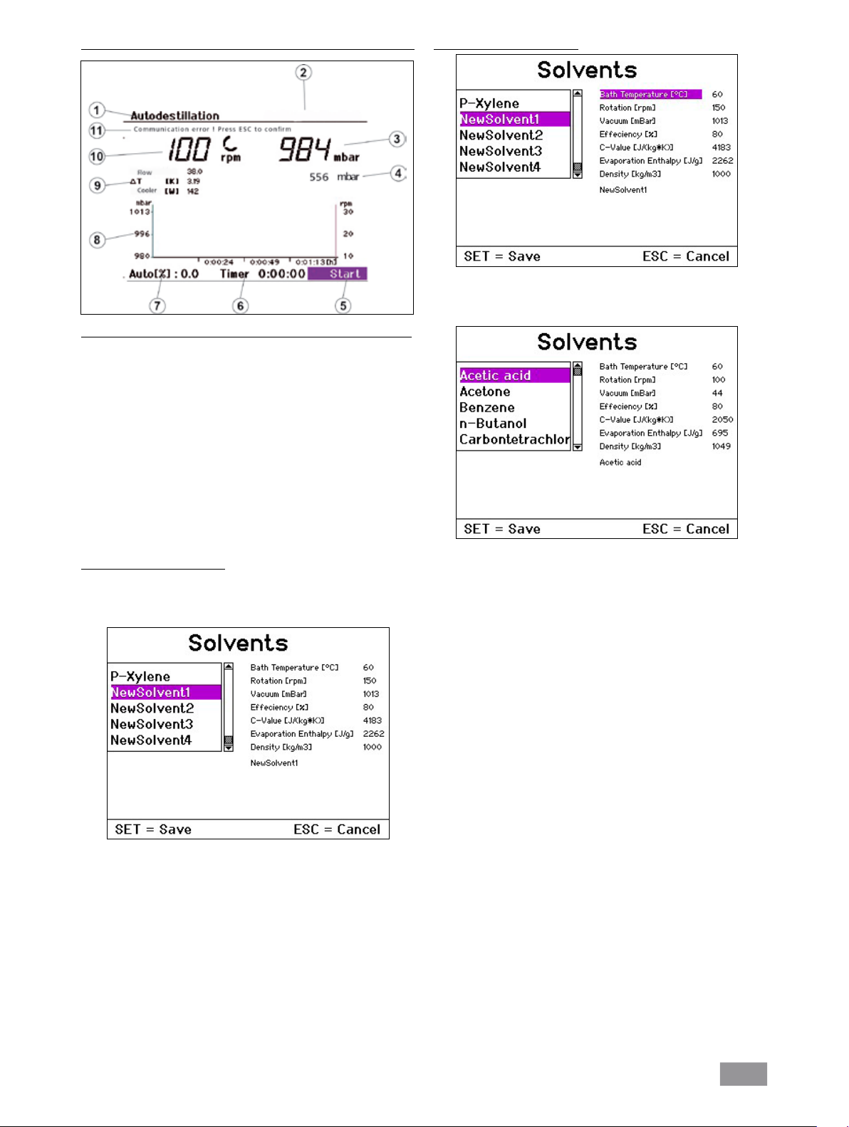
Menu "Mode distillation automatique sans détection de l'ébullition"
Affichage "Mode distillation automatique sans détection de l'ébullition"
1. Affichage du mode de fonctionnement
2. Champ de navigation Solvants
3. Affichage du vide (valeur réelle)
4. Affichage du vide (valeur de consigne)
5. Champ de navigation "Start/Stop" de la distillation
6. Affichage du minuteur
7. Affichage de la progression de la distillation
(% de la quantité du distillat nécessaire)
8. Diagramme vide-rotation-temps
9. Affichage du débit, de la température différentielle et de la
puissance du refroidisseur
10. Affichage de la rotation (valeur de consigne) et du symbole de
rotation
11. Affichage de l'erreur en cas d'erreur, sinon affichage de l'état
Solvants définis par l'utilisateur
Dans l'affichage des solvants, choisissez la plage NewSolvent1 ...
NewSolvent5.
Choisissez l'un des solvants et appuyez sur le bouton rotatif/bouton-
poussoir.
Modifier la sélection du solvant
Sélectionnez le champ de navigation "Solvants" en tournant le bouton
rotatif/bouton-poussoir vers la gauche ou la droite.
Appuyez sur le bouton rotatif/bouton-poussoir pour afficher le choix
de solvants.
Sélectionnez un solvant en tournant le bouton rotatif/bouton-poussoir
vers la gauche ou la droite.
Appuyez sur la touche SET.
Le solvant choisi est utilisé pour la distillation suivante.
Remarque : les paramètres s'affichent pour chaque solvant. Vous ne
pouvez modifier ces paramètres que pour les solvants que vous avez définis UserSolvent1 ... UserSolvent5. Ceci est décrit à la section suivante.
Vous pouvez maintenant modifier tous les paramètres du solvant affichés.
Sélectionnez le paramètre à changer en tournant le bouton rotatif/
bouton-poussoir vers la gauche ou la droite.
Appuyez sur le bouton rotatif/bouton-poussoir.
Modifiez le paramètre choisi en tournant le bouton rotatif/bouton-
poussoir vers la gauche/la droite.
Appuyez sur le bouton rotatif/bouton-poussoir.
Mémorisez toutes les valeurs avec la touche SET.
NewSolvent1 est sélectionné comme solvant actuel.
Remarque: un retour dans la fenêtre de sélection n'est pas possible.
92
Page 93

Menu "Mode distillation automatique avec détection de l'ébullition"
Menu "Mode distillation automatique sans détection de l'ébullition"
1. Operating mode display
2. Control field for solvent
3. Vacuum display (actual value)
4. Vacuum display (target value)
5. Control field for „Start/ Stop“ distillation
6. Timer display
7. Distillation progress indicator
(% of required quantity of distillate)
8. Vacuum-rotation-time graph
9. Display of flow rate, differential temperature, and condenser heat
rejection rate
10. Affichage de la rotation (valeur de consigne) et du symbole de
rotation
11. Affichage de l'erreur en cas d'erreur, sinon affichage de l'état
Remarque: la distillation en fonction du volume n'est pas possible car le
solvant doit être connu dans ce mode.
Dans ce mode, il est possible de définir la température du bain et la
vitesse de rotation de l'entraînement rotatif au lieu d'une sélection du
solvant via le champ de navigation 'Détection de l'ébullition'.
Début de la distillation automatique
Appuyez sur le bouton rotatif/bouton-poussoir sur le champ "Start"
ou "Continuer". Si les options "Distillation 100%" ou "Séchage" sont activées, la distillation démarre immédiatement dès lors que les conditions
sont remplies.
Avec le type de distillation "Volume", des paramètres de distillation sont
saisis dans un autre écran.
Sélectionnez la rubrique souhaitée en tournant le bouton rotatif/bou-
ton-poussoir vers la gauche ou la droite.
Appuyez sur le bouton rotatif/bouton-poussoir.
Tournez le bouton rotatif/bouton-poussoir pour modifier la valeur ou le
réglage (la taille de la modification dépend de la vitesse de rotation).
Appuyez à nouveau sur le bouton-poussoir/bouton rotatif pour termi-
ner la modification.
Distillation
Le type de distillation, sélectionné sous Réglages/Distillation, s'affiche ici
et ne peut plus être modifié.
Modèle
Saisissez la quantité qui se trouve dans le ballon modèle.
Distillat
Saisissez la quantité qui doit être distillée.
Efficacité
Pour le bilan, la saisie d'une efficacité thermique exacte est nécessaire.
L'efficacité dépend de la totalité des conditions de distillation et n'est
d'abord qu'une estimation. C'est pourquoi, le premier tour de distillation
ne sert qu'à l'étalonnage. A la fin de la distillation, déterminez la quantité
réellement distillée et calculez l'efficacité réelle avec la formule suivante :
m
ηth . m
ηP =
(calc)
(gem)
ηP Degré d'efficacité réel
ηth Degré d'efficacité estimé
m
Quantité de distillat mesurée
(gem)
Quantité de distillat prescrite (calculée)
m
(calc)
Pour les distillations suivantes, saisissez l'efficacité réelle ainsi définie et
les distillations suivantes seront exécutées automatiquement avec une
précision suffisante dans les mêmes conditions de distillation et de lieu.
Fin de la distillation automatique
La distillation automatique se termine selon les critères suivants :
En fonction du volume
Le bilan de la quantité de distillat prescrite a été fait.
100% Distillation
La différence de température du réfrigérant mesurée est inférieure à une
valeur de consigne, le solvant est totalement évaporé.
En outre, la distillation peut aussi être arrêtée manuellement:
Appuyez sur le bouton rotatif/le bouton poussoir sur le champ d'affi-
chage "Stop".
93
Page 94

Menu "Distillation définie par l'utilisateur"
Affichage "Distillation définie par l'utilisateur"
1. Affichage du mode de fonctionnement
2. Champ de navigation pour la procédure de distillation
3. Affichage du vide (valeur réelle)
4. Affichage du vide (valeur de consigne)
5. Champ de navigation "Start/Stop" de la distillation
6. Affichage du minuteur
7. Diagramme vide-rotation-temps
8. Affichage du débit, de la température différentielle et de la puissance
du refroidisseur
9.
Affichage de la rotation (valeur de consigne) et du symbole de rotation
10. Affichage de l'erreur en cas d'erreur, sinon affichage de l'état
Modifier une procédure
Sélectionnez la procédure à modifier et appuyez sur le bouton rotatif/
bouton-poussoir. Le champ d'affichage "Supprimer et nouveau" est
activé.
Si vous appuyez sur le bouton rotatif/bouton-poussoir dans le champ
d'affichage "Supprimer et nouveau", la procédure est supprimée.
Vous pouvez maintenant ajouter de nouvelles étapes de procédure pour
le vide et la rotation.
Vide
En tournant le bouton rotatif/bouton-poussoir vers la gauche/la droi-
te, sélectionnez "Vide".
Appuyez sur le bouton rotatif/bouton-poussoir.
Saisissez une valeur en tournant le bouton rotatif/bouton-poussoir
vers la gauche/la droite.
Appuyez sur le bouton rotatif/bouton-poussoir.
Durée
En tournant le bouton rotatif/bouton-poussoir vers la gauche/la droi-
te, sélectionnez "Durée".
Appuyez sur le bouton rotatif/bouton-poussoir.
Saisissez une valeur en tournant le bouton rotatif/bouton-poussoir
vers la gauche/la droite.
Appuyez sur le bouton rotatif/bouton-poussoir. Une nouvelle étape de
procédure est définie avec la paire de valeurs vide-durée et ajoutée à la
procédure. Le diagramme est actualisé.
Sélectionnez "Procédure" en tournant le bouton rotatif/bouton-pous-
soir vers la gauche ou la droite.
Appuyez sur le bouton rotatif/bouton-poussoir.
“Procédures” s'affiche.
Sélectionnez une procédure en tournant le bouton rotatif/bouton-
poussoir vers la gauche ou la droite.
Appuyez sur la touche SET.
La procédure choisie est utilisée pour la distillation suivante.
Remarque: pour chaque procédure, le diagramme vide-rotation-temps
s'affiche. Vous pouvez modifier les paramètres pour chaque procédure.
Ceci est décrit à la section suivante. En outre, vous pouvez mémoriser
le déroulement d'une distillation manuelle comme procédure, voir le
paragraphe "Mode manuel".
Rotation
En tournant le bouton rotatif/bouton-poussoir vers la gauche/la droi-
te, sélectionnez "Rotation".
Appuyez sur le bouton rotatif/bouton-poussoir.
Saisissez une valeur en tournant le bouton rotatif/bouton-poussoir
vers la gauche/la droite.
Appuyez sur le bouton rotatif/bouton-poussoir.
Durée
En tournant le bouton rotatif/bouton-poussoir vers la gauche/la droi-
te, sélectionnez "Durée".
Appuyez sur le bouton rotatif/bouton-poussoir.
Saisissez une valeur en tournant le bouton rotatif/bouton-poussoir
vers la gauche/la droite.
Appuyez sur le bouton rotatif/bouton-poussoir Une nouvelle étape de
procédure est définie avec la paire de valeurs rotation-durée et ajoutée
à la procédure. Le diagramme est actualisé.
Les étapes vide, durée et rotation ne peuvent être répétées que vingt
fois maximum.
Touche SET: pour quitter le menu. La nouvelle procédure créée est mémorisée et sélectionnée comme procédure actuelle.
Touche ESC: pour quitter le menu. Toutes les modifications sont annulées.
94
Page 95

Arrêt de la distillation définie par l'utilisateur
La distillation définie par l'utilisateur s'arrête automatiquement à la fin
de toutes les étapes de la procédure actuelle. En outre, l'arrêt manuel
est possible en appuyant avec le bouton rotation/bouton-poussoir sur
le champ "Stop".
Mode Stand-by
Appuyez sur la touche "Power".
L'appareil se met en Stand-by.
Appuyez à nouveau sur la touche "Power".
Le menu principal apparaît et l'appareil est prêt à fonctionner.
95
Page 96

Guidage par menus
Procedure 1
Procedure 2
Procedure 3
Procedure 4
Procedure 5
Procedure 6
Procedure 7
Procedure 8
Procedure 9
Procedure 10
Puissance frigorifique maximale
Puissance frigorifique maximale
Contrôle du débit
Unité de quantité
Détection de l'ébullition
Graduation du vide
Unité de vide
Minuteur
Graduation du temps
Graduation de la rotation
Acétone
Eau
Toluène
N-panthénol
Benzol
UserSolvent 1
UserSolvent 2
Temérature bain chauffant
Rotation
Rotation
Vide
Degré d'efficacité
Valeur C
Température du bain chauffant
UserSolvent 3
UserSolvent 4
UserSolvent 5
Quantité du modèle
Quantité de distillat
Degré d'efficacité
Enthalpie de l'évaporation
Densité
Type de distillation
Séchage
Valeur limite de la puissance frigorifique
Hystérèse
Graduation du temps
Suppression de la procédure
Vide
Durée
Rotation
Durée
Confirmer
Intervalle droite/gauche
Détection de l'ébullition non
Détection de l'ébullition oui
Valeur de consigne et valeur réelle de rotation
Valeur de consigne de vide
Affichage du minuteur
Start/Stop
Mémorisation, navigation dans les procédures
Affichage des erreurs
Affichage du diagramme vide-rotation-temps
Détection de l'ébullition activée ?
Valeur de consigne de rotation
Valeur de consigne et valeur réelle de vide
Affichage du minuteur
Champ de navigation Solvants/ Détection de l'ébullition
Start/Stop, autres paramètres
Procedure 1
Procedure 2
Procedure 3
Procedure 4
Procedure 5
Procedure 6
Procedure 7
Procedure 8
Procedure 9
Procedure 10
Valeur de consigne de rotation
Valeur de consigne et valeur réelle de vide
Affichage du diagramme vide-rotation-temps
Affichage de la progression de la distillation
Affichage des erreurs
Affichage du débit, de la température différentielle et de la puissance du refroidisseur
Affichage du minuteur
Affichage du diagramme vide-rotation-temps
Champ de navigation de la procédure de distillation
Start/Stop, autres paramètres
Affichage des erreurs
Affichage du débit, de la température différentielle et de la puissance du refroidisseur
Distillation
Vide
Entraînement
Eau
Huile
Milieu du bain
English
Deutsch
Français
RV10.5001
RV10.4001/2
Bain chauffant
Langue
Service
Español
中文
Polski
日本語
RV10.4003 Vanne
V4 Mise à l'air libre
Pompe
Alignement
Heures de fonctionnement
Menu principal
Mode manuel
Mode distillation automatique
Mode défini par l'utilisateur
Réglages
Ecran de démarrage
96
Page 97

Réglage de la butée finale inférieure
Attention ! En fonction de la taille du ballon, de l'angle de réglage de
l'entraînement de rotation, ainsi que la position du bain chauffant et
du dispositif de levage, le ballon d'évaporation peut se lever sur le bain
chauffant. Risque de bris de verre !
Limitez la position inférieure du dispositif de levage avec la butée finale variable.
En mode manuel, un positionnement au choix du dispositif de levage est
possible avec les touches “ ” et “ ”. Il n'y a pas de coupure automatique
en cas de collision.
Appuyez sur la touche “ ” jusqu'à ce que le dispositif de levage att-
eigne la position souhaitée.
Remarque : le ballon d'évaporation doit s'immerger aux 2/3 dans le
bain chauffant.
Pour déplacer l'élément de butée (Q), appuyez sur le bouton central
(R) à l'avant du dispositif de levage (fig. 18).
Poussez la butée (Q) dans la position souhaitée (fig. 19).
Appuyez sur la touche “ ” jusqu'à ce que le dispositif de levage att-
eigne la butée finale supérieure.
Remarque : la course est limitée de 0 à 6 cm.
R
Remplissage du ballon d'évaporation
Avant de remplir le ballon d'évaporation, l'appareillage en verre est réglé
sur la pression théorique via la commande de vide (controller).
Remplissez maintenant le ballon d'évaporation avec la conduite de
réapprovisionnement, voir fig. 30.
En raison de la dépression présente, le solvant est aspiré dans le bal-
lon d'évaporation. Ceci permet de réduire au maximum les pertes de
solvants par aspiration.
Avant d'appliquer le vide, vous pouvez aussi remplir manuellement le
ballon d'évaporation. Le ballon d'évaporation ne doit pas être rempli
au-delà de la moitié de son volume.
Remarque : Attention ! La charge maximale autorisée (ballon
d'évaporation et son contenu) est de 3 kg.
Q
Fig. 28
Fig. 29
Vérifiez le fonctionnement de la coupure en fin de course :
Abaissez le dispositif de levage en appuyant en continu sur la touche
“ ”.
L'entraînement s'arrête automatiquement dès qu'il a atteint sa posi-
tion inférieure définie.
Ramenez l'entraînement en position supérieure.
Pour activer le levage de sécurité après un arrêt prolongé, avant de com-
mencer la distillation, mettez le levage motorisé plusieurs fois en butée
inférieure ou en butée supérieure (voir chapitre Consignes de sécurité Dispositif de levage de sécurité)!
Installation du bain chauffant
Lisez également le mode d'emploi du bain chauffant IKA® HB 10!
Abaissez le dispositif de levage dans sa position inférieure et vérifiez la
position du bain chauffant par rapport à celle du ballon d'évaporation.
En cas d'utilisation d'un ballon d'évaporation plus grand (2 ou 3 litres)
et selon l'angle de l'entraînement de rotation, vous pouvez décaler le
bain chauffant de 50 mm vers la droite.
Remplissez le bain chauffant d'agent de mise à température jusqu'à ce
que le ballon d'évaporation soit immergé aux 2/3.
Allumez l'entraînement de rotation et augmentez lentement la vitesse
de rotation.
Remarque : évitez la formation de rides.
Allumez le bain chauffant au niveau de l'interrupteur principal.
Remarque : évitez les tensions sur le verre par l'utilisation de températures différentes pour le ballon d'évaporation et le bain chauffant lors de
la descente du ballon d'évaporation dans le bain chauffant !
Remarque : si vous utilisez des accessoires autres que des accessoires
d'origine IKA®, la course de déplacement de 50 mm du bain chauffant
peut ne plus être suffisante, en particulier en cas d'utilisation d'un ballon
d'évaporation de 3 l et d'un dispositif anti-mousse.
Utilisez la plaque IKA® RV 10.3000 pour étendre la course de déplacement du bain chauffant de 150 mm.
Fig. 30
97
Page 98

Entretien et nettoyage
Le fonctionnement de l’appareil ne nécessite pas d’entretien. Il est simplement
soumis au vieillissement naturel des pièces et à leur taux de défaillances statistique.
Le joint d'étanchéité du condenseur en verre doit être contrôlé à intervalle régulier et remplacé si nécessaire.
Débranchez la prise secteur pour la nettoy-age.
Pour nettoyer la commande, il faut utiliser uniquement de l’eau avec un
produit d’addition au détergent contenant un dérivé tensio-actif ou de
l’alcool isopropylique si l’encrassement est plus important.
La commande de pièces de rechange
Lors de la commande de pièces de rechange, veuillez indiquer:
- le type de l’appareil,
- le numéro de fabrication, voir la plaque d’identification,
- le numéro de position et la désignation de la pièce de rechange, voir
www.ika.com, le tableau des pièces de rechange et catalogue des
pièces de rechange.
Accessoires
Réparation
En cas de réparation n’envoyez que des appareils nettoyés et exempts de
matières nocives pour la santé. Utilisez pour cela le formulaire «Certi-
ficat de régularité», imprimez le formulaire téléchargeable sur le site
Web d'IKA®: www.ika.com.
Renvoyez l’appareil dans son emballage d’origine. Les emballages de
stockage ne sont pas susants pour le renvoi. Utilisez un emballage de
transport supplémentaire adapté.
Dispositif de levage de sécurité
Le dispositif de levage de sécurité doit être contrôlé quotidiennement
avant utilisation!
Après un arrêt prolongé (env. quatre semaines), mettez plusieurs fois le
levage motorisé en butée inférieure ou supérieure avant de commencer
la distillation (voir chapitre Consignes de sécurité - Dispositif de levage de
sécurité)! Si le dispositif de levage de sécurité ne fonctionne plus, veuillez
contacter le service après-vente IKA®.
RV 10.1 NS 29/32 Verrerie verticale (1)
RV 10.10 NS 29/32 Verrerie verticale, avec revêtement (1)
RV 10.2 NS 29/32 Verrerie diagonale (2)
RV 10.20 NS 29/32 Verrerie diagonale, avec revêtement (2)
RV 10.700 NS 29/42 Verrerie verticale (1)
RV 10.710 NS 29/42 Verrerie verticale, avec revêtement (1)
RV 10.800 NS 29/42 Verrerie diagonale (2)
RV 10.810 NS 29/42 Verrerie diagonale, avec revêtementt (2)
RV 10.900 NS 24/40 Verrerie verticale (1)
RV 10.910 NS 24/40 Verrerie verticale, avec revêtement (1)
RV 10.1000 NS 24/40 Verrerie diagonale (2)
RV 10.1010 NS 24/40 Verrerie diagonale, avec revêtement (2)
RV 10.3 Réfrigérant intensif vertical avec distributeur (1)
RV 10.30
RV 10.4 Réfrigérant à neige carbonique (2)
RV 10.40 Réfrigérant à neige carbonique, avec revêtment (2)
RV 10.5 Réfrigérant vertical avec distributeur et soupape d’arrêt
pour la distillation à reflux (3)
RV 10.50
la distillation à reflux, avec revêtment (3) (pas d'illustration)
RV 10.6 Réfrigérant intensif vertical avec distributeur et soupa pe (3)
RV 10.60 Réfrigérant intensif vertical avec distributeur et soupa pe, avec revêtment (3)
HB 10.1 Écran de protection (Bain chauffant HB 10)
HB 10.2 Capot de protection (Bain chauffant HB 10)
RV 10.70 NS 29/32 Traversée de vapeur
RV 10.71 NS 24/29 Traversée de vapeur
RV 10.72 NS 29/42 Traversée de vapeur
RV 10.73 NS 24/40 Traversée de vapeur
Réfrigérant intensif vertical avec distributeur, avec revêtment (1)
(pas d'illustration)
Réfrigérant vertical avec distributeur et soupape d’arrêt pour
RV 10.74 NS 29/32 Traversée de vapeur, court,
pour distillation à reflux
RV 10.75 NS 24/29 Traversée de vapeur, court,
pour distillation à reflux
RV 10.76 NS 29/42 Traversée de vapeur, court,
pour distillation à reflux
RV 10.77 NS 24/40 Traversée de vapeur, court,
pour distillation à reflux
98
Page 99

RV 10.80 NS 29/32 Ballon d'évaporation 50 ml
RV 10.81 NS 29/32 Ballon d'évaporation 100 ml
RV 10.82 NS 29/32 Ballon d'évaporation 250 ml
RV 10.83 NS 29/32 Ballon d'évaporation 500 ml
RV 10.84 NS 29/32 Ballon d'évaporation 1000 ml
RV 10.85 NS 29/32 Ballon d'évaporation 2000 ml
RV 10.86 NS 29/32 Ballon d'évaporation 3000 ml
RV 10.90 NS 24/32 Ballon d'évaporation 50 ml
RV 10.91 NS 24/32 Ballon d'évaporation 100 ml
RV 10.92 NS 24/32 Ballon d'évaporation 250 ml
RV 10.93 NS 24/32 Ballon d'évaporation 500 ml
RV 10.94 NS 24/32 Ballon d'évaporation 1000 ml
RV 10.95 NS 24/32 Ballon d'évaporation 2000 ml
RV 10.96 NS 24/32 Ballon d'évaporation 3000 ml
RV 10.97 NS 24/40 Ballon d'évaporation 1000 ml
RV 10.2001 NS 29/42 Ballon d'évaporation 50 ml
RV 10.2002 NS 29/42 Ballon d'évaporation 100 ml
RV 10.2003 NS 29/42 Ballon d'évaporation 250 ml
RV 10.2004 NS 29/42 Ballon d'évaporation 500 ml
RV 10.87 NS 29/42 Ballon d'évaporation 1000 ml
RV 10.2005 NS 29/42 Ballon d'évaporation 2000 ml
RV 10.2006 NS 29/42 Ballon d'évaporation 3000 ml
RV 10.2007 NS 24/40 Ballon d'évaporation 50 ml
RV 10.2008 NS 24/40 Ballon d'évaporation 100 ml
RV 10.2009 NS 24/40 Ballon d'évaporation 250 ml
RV 10.2010 NS 24/40 Ballon d'évaporation 500 ml
RV 10.2011 NS 24/40 Ballon d'évaporation 1000 ml
RV 10.2012 NS 24/40 Ballon d'évaporation 2000 ml
RV 10.2013 NS 24/40 Ballon d'évaporation 3000 ml
RV 10.100 KS 35/20 Ballon de récupération 100 ml
RV 10.101 KS 35/20 Ballon de récupération 250 ml
RV 10.102 KS 35/20 Ballon de récupération 500 ml
RV 10.103 KS 35/20 Ballon de récupération 1000 ml
RV 10.104 KS 35/20 Ballon de récupération 2000 ml
RV 10.105 KS 35/20 Ballon de récupération 3000 ml
RV 10.200 KS 35/20 Ballon de récupération, avec revêtement 100 ml
RV 10.201 KS 35/20 Ballon de récupération, avec revêtement 250 m
RV 10.202 KS 35/20 Ballon de récupération, avec revêtement 500 ml
RV 10.203 KS 35/20 Ballon de récupération, avec revêtement1000 ml
RV 10.204 KS 35/20 Ballon de récupération, avec revêtement 2000 ml
RV 10.205 KS 35/20 Ballon de récupération, avec revêtement 3000 m
RV 10.300 NS 29/32 Ballon de poudre 500 ml
RV 10.301 NS 29/32 Ballon de poudre 1000 ml
RV 10.302 NS 29/32 Ballon de poudre 2000 ml
RV 10.303 NS 24/29 Ballon de poudre 500 ml
RV 10.304 NS 24/29 Ballon de poudre 1000 ml
RV 10.305 NS 24/29 Ballon de poudre 2000 ml
RV 10.2014 NS 29/32 Ballon de poudre 500 ml
RV 10.2015 NS 29/32 Ballon de poudre 1000 ml
RV 10.2016 NS 29/32 Ballon de poudre 2000 ml
RV 10.217 NS 24/40 Ballon de poudre 500 ml
RV 10.218 NS 24/40 Ballon de poudre 1000 ml
RV 10.219 NS 24/40 Ballon de poudre 2000 ml
RV 10.400 NS 29/32 Cylindre d'évaporation 500 ml
RV 10.401 NS 29/32 Cylindre d'évaporation 1500 ml
99
Page 100

RV 10.402 NS 24/29 Cylindre d'évaporation 500 ml
RV 10.403 NS 24/29 Cylindre d'évaporation 1500 ml
RV 10.2020 NS 29/42 Cylindre d'évaporation 500 ml
RV 10.2021 NS 29/42 Cylindre d'évaporation 1500 ml
RV 10.2022 NS 24/40 Cylindre d'évaporation 500 ml
RV 10.2023 NS 24/40 Cylindre d'évaporation 1500 ml
RV 10.500 NS 29/32 Dispositif anti-mousse
RV 10.501 NS 24/29 Dispositif anti-mousse
RV 10.2024 NS 29/42 Dispositif anti-mousse
RV 10.2025 NS 24/40 Dispositif anti-mousse
RV 10.600 NS 29/32 Araignée de distillation avec 6 douilles de distillation
RV 10.601 NS 29/32 Araignée de distillation avec 12 douilles de distillation
RV 10.602 NS 29/32 Araignée de distillation avec 20 douilles de distillation
RV 10.603 NS 24/29 Araignée de distillation avec 6 douilles de distillation
RV 10.604 NS 24/29 Araignée de distillation avec 12 douilles de distillation
RV 10.605 NS 24/29 Araignée de distillation avec 20 douilles de distillation
RV 10.2026 NS 29/42 Araignée de distillation avec 6 douilles de distillation
RV 10.2027 NS 29/42 Araignée de distillation avec 12 douilles de distillation
RV 10.2028 NS 29/42 Araignée de distillation avec 20 douilles de distillation
RV 10.2029
RV 10.2030 NS 24/40 Araignée de distillation avec 12 douilles de distillation
RV 10.2031 NS 24/40 Araignée de distillation avec 20 douilles de distillation
RV 10.610
RV 10.606 NS 29/32 raignée de distillation avec 5 ballons 50 ml
RV 10.607 NS 29/32 raignée de distillation avec 5 ballons 100 ml
RV 10.608 NS 24/29 raignée de distillation avec 5 ballons 50 ml
RV 10.609 NS 24/29 raignée de distillation avec 5 ballons 100 ml
RV 10.2032 NS 29/42 raignée de distillation avec 5 ballons 50 ml
RV 10.2033 NS 29/42 raignée de distillation avec 5 ballons 100 ml
RV 10.2034 NS 24/40 raignée de distillation avec 5 ballons 50 ml
RV 10.2035 NS 24/40 raignée de distillation avec 5 ballons 100 ml
RV 10.3000 Plaque
RV 10.4001 Electrovanne vide de maison (1)
RV 10.4002 Electrovanne vide de laboratoire (2)
RV 10.4003 Commande de pompe avec électrovanne (3))
RV 10.5001 Vanne d'étranglement d'eau (4), uniquement pour le
fonctionnement sur conduite d'eau!
RV 10.5002 Filtre (5)
RV 10.5003 Vanne de régulation de pression (6)
NS 24/40 Araignée de distillation avec 6 douilles de distillation
Douille de distillation 20 ml
RV 10.8001 Joint d’étanchéité, PTFE compound
PC 1.1 Câble
Labworldsoft
®
100
 Loading...