

IKA Rotavisc lo-vi, Rotavisc me-vi, Rotavisc hi-vi I, Rotavisc hi-vi II Operating Instructions Manual
Page 1
20000009673
Rotavisc lo-vi_me-vi_hi-vi I_hi-vi II_042018
IKA Rotavisc lo-vi
IKA
IKA
IKA
Rotavisc me-vi
Rotavisc hi-vi I
Rotavisc hi-vi II
Page 2
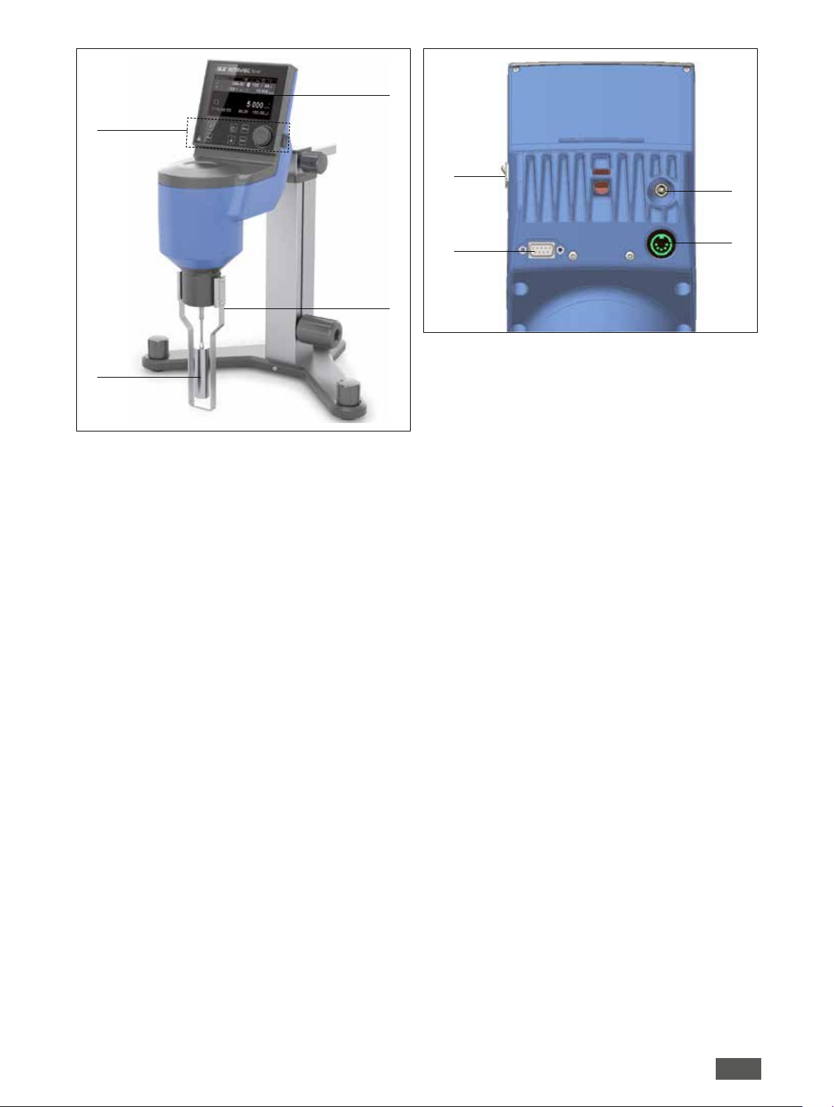
Fig. 1
1
Fig. 2
4
5
8
6
3
1 Control panel
2
2 Spindle
3 Guard rail
4 Display
5 USB interface
6 RS 232 interface
7 Connection socket for temperature sensor
8 Connection socket for power cord
7
2
Page 3
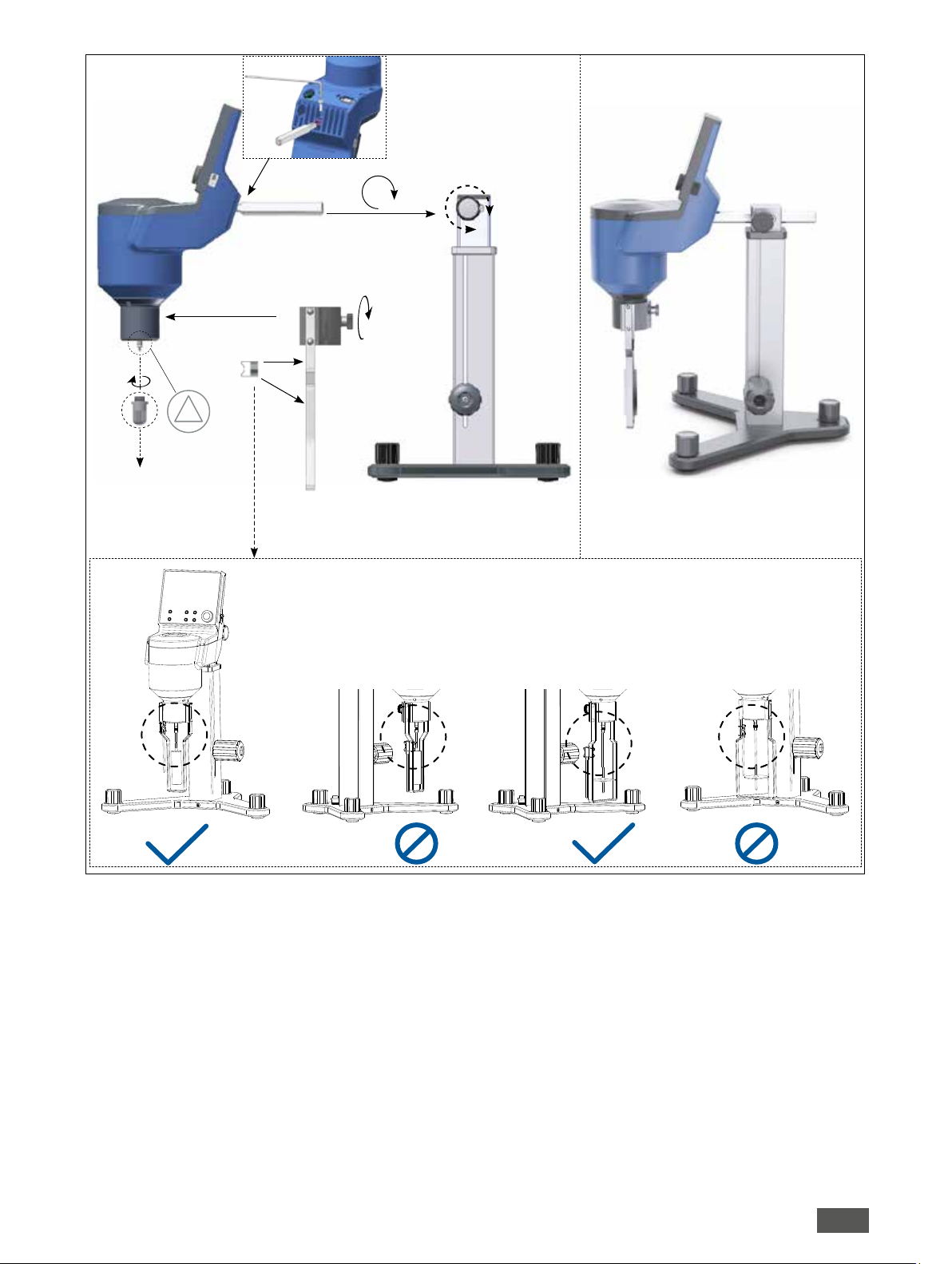
Fig. 3
lo-vi
!
me-vi
lo-vi
lo-vi me-vi me-vi
3
Page 4
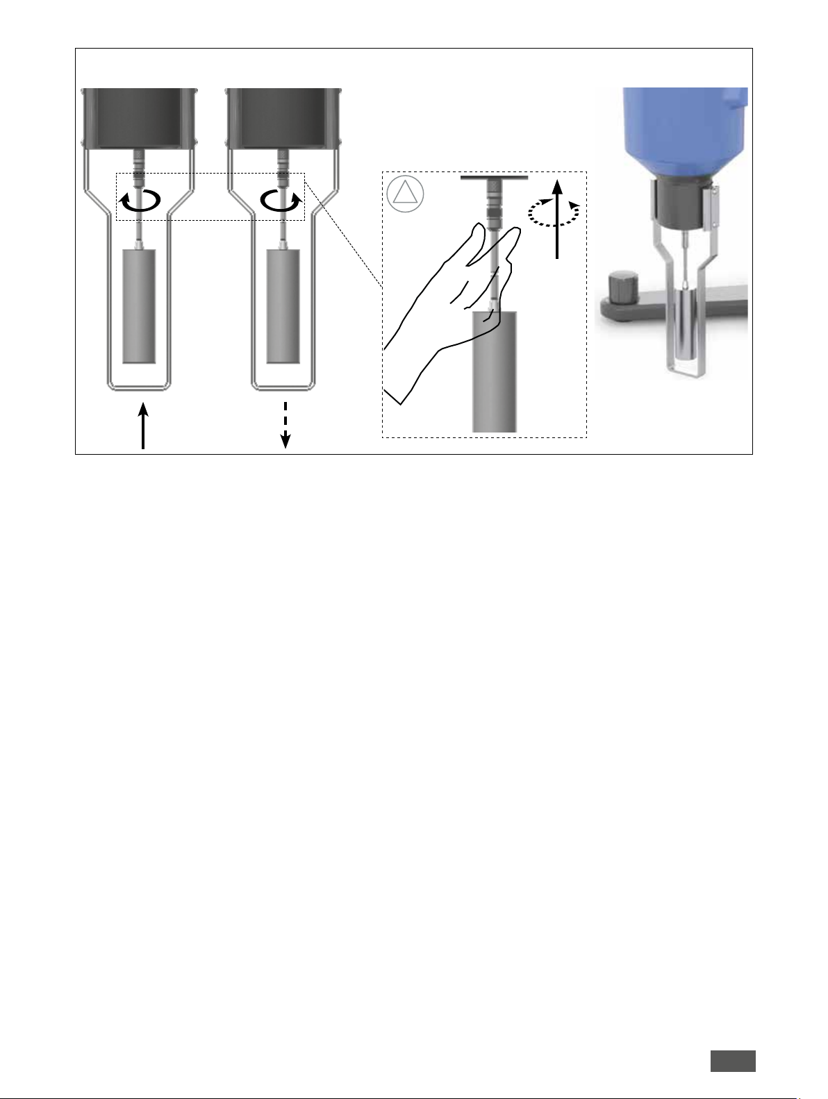
Fig. 4
!
4
Page 5

Source language: German
Contents
Page
Declaration of conformity 5
Safety instructions 5
Correct use 6
Unpacking 7
Mounting 7
Switching on the device 8
Useful information 9
Operation 10
Interfaces and outputs 16
Declaration of conformity
EN
Maintenance and cleaning 17
Accessories 17
Error message 17
Warranty 18
Technical data 18
Appendix A “Range coecient“ 19
Appendix B “ASTM specifications“ 21
We declare under our sole responsibility that this product corresponds to the regulations 2014/35/EU, 2006/42/EC, 2014/30/EU and
2011/65/EU and conforms with the standards or standardized documents: EN 61010-1 and EN 61326-1.
A copy of the complete EU Declaration of Conformity can be requested at sales@ika.com.
Safety instructions
Explication of warning symbols
Indicates an (extremely) hazardous situation, which, if not avoided, will result in death, serious injury.
Indicates a hazardous situation, which, if not avoided, can result in death, serious injury.
Indicates a potentially hazardous situation, which, if not avoided, can result in injury.
Indicates practices which, if not avoided, can result in equipment damage.
!
General information
Read the operating instructions completely before starting up and follow the safety instructions.
Keep the operating instructions in a place where it can be accessed by everyone.
Ensure that only trained staff work with the device.
Follow the safety instructions, guidelines, occupational health, safety and accident prevention regulations.
The viscometer is designed to to be operated indoors!
Device configuration
Set up the stand in a spacious area on an even, stable, clean, non-slip, dry and fireproof surface.
5
Page 6

Work with the device
Danger! ( )
› Wear your personal protective equipment in accordance with the hazard category of the medium to be processed, otherwise there
is a risk of:
- splashing of liquids
- projectile parts
- body parts, hair, clothing and jewelry getting caught.
› Do not operate the device in explosive atmospheres, with hazardous substances or under water.
Warning! (
› There may be electrostatic activity between the medium and the spindle which could cause a direct danger.
Caution! (
› The user should ensure that the substances under testing do not release poisonous, toxic or flammable gases at the temperatures
)
)
which they are subjected to during the testing.
› Protect the device and accessories from bumping and impacting.
Note! ( )
› Covering or parts that are capable of being removed from the unit without accessory reattached to the unit for safe operation in
order to prevent, for example, the ingress of fluids, foreign matter, etc.
› The spindle connector (left-hand thread M2.5 LH) is a sensitive coupling! No impact force action is allowed!
› Always hold the spindle connector by hand while attaching or loosening the measurment spindle, otherwise it will damage the pivot
and the jewel bearing inside the viscometer.
Do not put the viscometer in direct contact with sunlight or in the middle of any air flow (the temperature of the sample can be easily
influenced by the surrounding conditions).
Check the device and accessories for damage before each use. Do not use damaged components.
Only process media that will not react dangerously to the extra energy produced through processing. This also applies to any extra
energy produced in other ways, e.g. through light irradiation.
Process pathogenic materials only in closed vessels under a suitable fume hood.
If this device is used in a manner not specified by the manufacturer, the protection provided by the device may be impaired.
Do not use the device for any other purpose that is not described in this manual.
Accessories
Safe operation is only guaranteed with the accessories described in the ”Accessories” section.
Always disconnect the device from the mains supply before fitting accessories.
Observe the operating instructions of the accessories.
Power supply/Switching off the device
The device can only be disconnected from the mains supply by pulling out the mains plug or the connector plug.
The socket for the mains cord must be easily accessible.
The voltage stated on the type plate must correspond to the mains voltage.
Maintenance
Warning! ( )
› The machine must only be opened by trained specialists, even during repair. The device must be unplugged from the power supply
before opening. Live parts inside the device may still be live for some time after unplugging from the power supply.
Correct use
Use
The IKA Rotavisc must be used in conjunction with the IKA Rotastand to measure the viscosity of a fluid at the given temperature
and shear rate. The viscosity is a measure of resistance against the
fluid to flow.
Intended use: Stand device
Area of use (only indoors)
- Laboratories - Schools
- Pharmacies - Universities
The device is suitable for use in residential areas and all other areas
The safety of the user cannot be guaranteed:
- If the device is operated with accessories that are not supplied or
recommended by the manufacturer;
- If the device is operated improperly or contrary to the manufacturer’s specifications;
-
If the device or the printed circuit board are modified by the third
parties.
.
6
Page 7
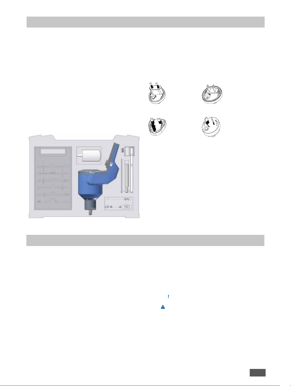
Unpacking
Unpacking
- Unpack the device carefully.
- Any damage should be notified immediately to the shipping
agent (post, rail or logistics company).
Delivery scope
Rotavisc (lo-vi/me-vi/hi-vi I/hi-vi II)
Spindle series lo-vi or me-vi
Temperature probe PT 100
PT 100 clamper
USB cable A – micro B 2.0.
Guard rail
Rod
Wrench
AC/DC adapter
Carrying case
- Operating instructions
- Warranty card
AC/DC adapter (
Adapter
Europe, Switzerland
Adapter
England
):
Adapter
USA, China
Adapter
Australia
Mounting
Secure the rod to the viscometer (see , Fig. 3 )
• Insert the rod to the viscometer and secure it by turning the
screw clockwise to the end position.
Secure the viscometer to the stand (see
• Insert the viscometer to the stand and fasten it by turning the
knob clockwise to the end position.
Secure the guard rail to the viscometer (see
• Place the guard rail on the viscometer and secure it by turning
the screw clockwise to the end position.
• Insert the PT 100 into the clamper. Mount the PT 100 with clam-
per onto the guard rail. For lo-vi rail, clamp at the upper portion,
while for me-vi rail, at the lower portion.
Remove the protection cap from the viscometer (see ,
Fig. 3)
• The protection cap protects the spindle connector from bump-
ing and impacting.
• Besides, the protection cap lifts the inside pivot up from the
, Fig. 3)
, Fig. 3)
jewel bearing when it is tightened to the end position, which
is also a good way to protect the jewel bearing from damage
during transportation.
• Remove the protection cap from the viscometer by carefully
turning it counterclockwise, and then place it in the hole of the
bottom plate .
Attach the spindle to the viscometer (see Fig. 4)
Caution! (
Protect the device and accessories from bumping and impacting.
Note! ( )
The spindle connector (left-hand thread M2.5 LH) is a sensitive coupling! No impact force action is allowed!
Always hold the spindle connector by hand while attaching or
loosening the measurment spindle, otherwise it will damage the
pivot and the jewel bearing inside the viscometer.
• With one hand, hold the spindle connector of the viscometer.
• With the other hand, insert the spindle into the spindle connector and turn the spindle counterclockwise to attach it to the
viscometer. To detach, turn it clockwise.
)
7
Page 8
Switching on the device
Check that the power supply matches the data on the rating plate.
Plug the AC adapter into a standard mains socket in order to supply the device with power.
Introduction
After switching on the viscometer, the information screen is displayed for 4-5 seconds, showing the device name, software version and series of the viscometer.
To cover a wide range of viscosity, 4 different types of devices are
available.
Depending on the used measurment spindle and the selected
speed, the viscosity range of the specific type varies, which you
may find it via:
lo-vi = low viscosity
me-vi = medium viscosity
hi-vi I = high viscosity I
hi-vi II = high viscosity II
Firmware update screen
The “Firmware update screen“ screen will be shown for 5 seconds.
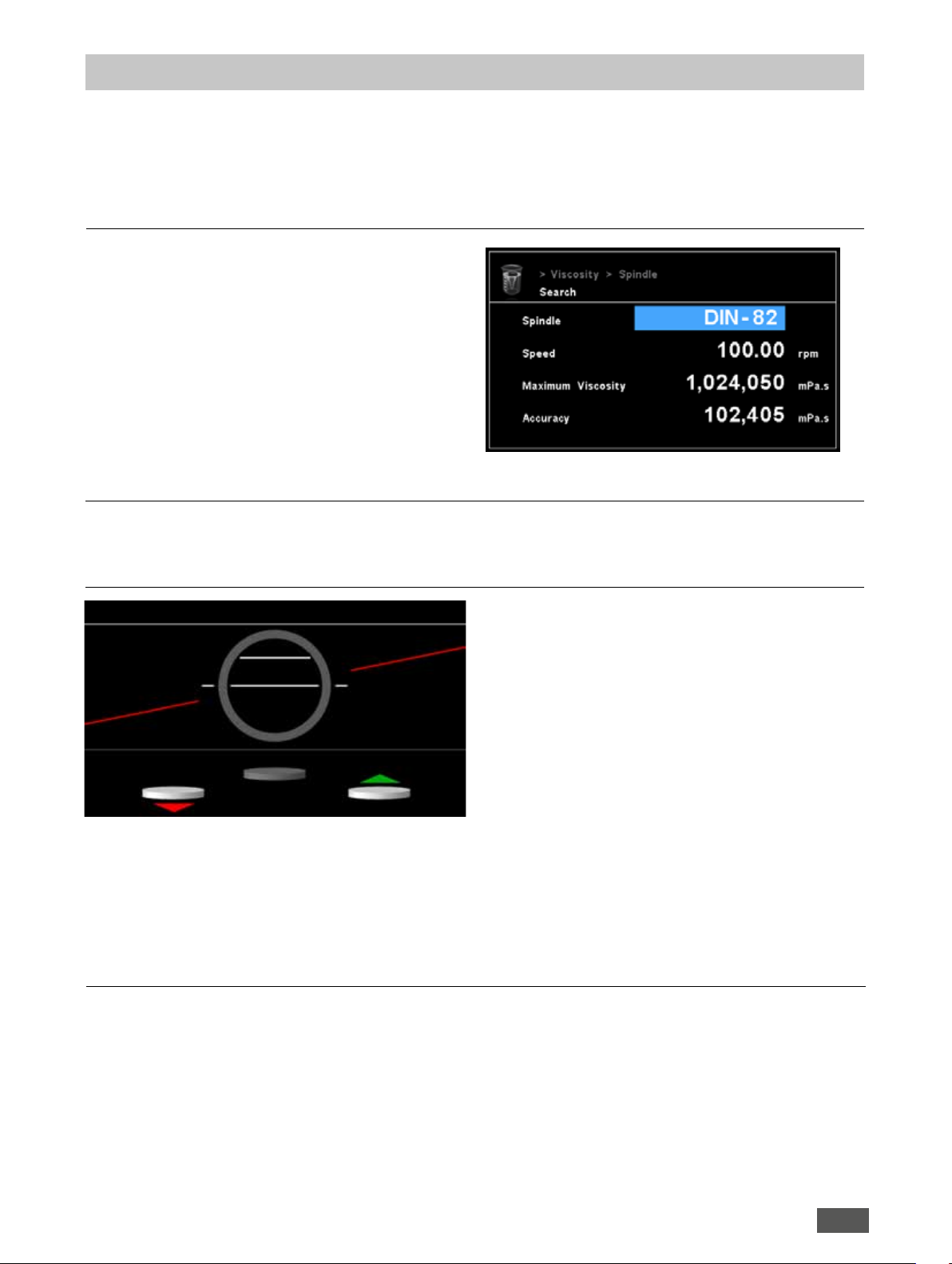
Level meter
Menu -> Viscosity -> Spindle -> Search
Observe the connection values and the ambient conditions (temperature, humidity, etc.) listed under “Technical data”.
Once these conditions are satisfied, and the mains plug has been
plugged in, the device is ready to operate.
Note: Firmware update screen can be modified by:
Menu -> Settings -> Display -> Firmware update screen
There are two moving lines:
• The red angular line pivoting around the center of the circle,
represents the rotation of the device around the X-axis. When
the line is horizontal (matching the white line), the device will be
in balance with the X-axis, and then the line color will turn from
red to green.
Device self checking
• Remove the spindle Press the knob
During this period, the spindle icon will move from the top to
the bottom.
Note: Remove the protection cap from the device.
Remove the spindle from the device.
• Device self checking...
During this period, the spindle icon will rotate.
• The small horizontal white line inside the circle, is moving vertically and it represents the rotation around the Y-axis. When it
matches the white line, the device will be in balance with the
Y-axis, then the line color will turn from white to green.
The three buttons represent the three stand levelers. The arrows
show in which direction they have to be adjusted (green = up;
red = down).
The adjustment steps are as follows:
• It is recommended that you adjust the X-axis first and the Y-axis
afterwards.
• After successfully aligning the X-axis, you can adjust the Y-axis.
If the X-axis gets out of balance while adjusting the Y-axis, go
back to the previous step.
• As soon as the small horizontal red line inside the circle matches
the center line, all the lines will turn green.
Always two possibilities of knob adjusting are shown, because the
knob position could be already at the limit.
When X-axis and Y-axis are both centered, the device is leveled.
Press the knob to confirm OK.
• Device self checking is done. After this step, the screen will
switch to the main screen.
Note: Device self checking will take approx. 30 seconds.
8
Page 9

Measurement principle
Useful information
The measuring principle of IKA Rotavisc is to use the stepping motor to drive a measuring spindle (which is immersed in the test fluid)
through a linearity calibrated spring sensor. The viscous resistance of
the fluid against the spindle is detected by the spring deflection. The
spring deflection is measured with a rotary transducer. The measurement range of IKA Rotavisc is determined by the spring, the spindle
and the speed. Please refer to Appendix B for “Range coefficient”.
There are four basic spring torque series offered by IKA:
Notes
• The viscosity is shown in units of centipoise (shown as “cP”) or
milliPascal-seconds (shown as“mPa•s“).
• The shear stress is shown in units of dynes/square centimeter (“D/
2
cm
”) or Newton/square meter (“N/m2”).
• The shear rate is shown in units of reciprocal seconds (“1/s”).
• The torque is shown in units of dyne-centimeters or Newton-meters.
• The torque percentage is shown as “xx.x %”.
The equivalent units of measurement in the CGS system are calculated using the following conversions:
Torque
Spindle
dyne•cm mNm
lo-vi 673.7 0.0673
me-vi 7187.0 0.7187
hi-vi I 14374.0 1.4374
hi-vi II 57496.0 5.7496
The device measurement range depends on the calibrated torque,
the higher torque means the wider range. All units of measurement
are displayed to either the CGS system or the SI system, which you
can choose via the menu.
SI CGS
Viscosity: 1 mPa•s = 1 cP
Shear stress: 1 Newton/m
2
= 10 Dyne/cm
2
Torque: 1 Newton-m = 107 dyne-cm
References to viscosity throughout this manual are done in SI units.
The IKA Rotavisc provides equivalent information in CGS units.
Base for reliable viscosity measurements is laminar flow! If the measurement spindle turns too fast, turbulence occurs. The result is not
valid.
Always consider a shown torque >10% and less 90%. Smaller and
bigger values will also show non valid viscosity values too.
Effect on accuracy when using accessory devices
The IKA Rotavisc has a stated accuracy of ±1 % of the full scale range
in use. This stated accuracy applies when the viscometer is used in
accordance with the operating instructions and the calibration test
fluid is used in accordance with the instructions provided by the fluid
supplier (including the critical parameters of temperature control and
stated fluid accuracy). IKA’s accuracy statement of ±1 % of the range in use applies to the IKA Rotavisc when used with the standard
spindles supplied with the device in a 600 ml Grin beaker.
IKA offers a range of accessories for use with the IKA Rotavisc to accommodate special measurement circumstances. These accessories,
while offering added capability to you, also contribute to an expanded measurement tolerance beyond the device accuracy of ±1 % of
Guard rail
IKA provides an lo-vi guard rail for lo-vi device and an me-vi guard rail
for me-vi/hi-vi I/hi-vi II devices.
The spindle guard rail protects the spindle from damage and provide
a higher accurancy.
the range in use. This expanded measurement tolerance is a function
of many parameters including spindle geometry, accessory alignment
accuracy, sample volume requirement, and sample introduction techniques. The effect of these elements on measurement tolerance must
be considered when verifying the calibration of your IKA Rotavisc.
Sample temperature in all test circumstances is very important, and
will also add an additional expanded tolerance depending on the
temperature control system and the calibration verification tests begin with the standard viscometer spindles as detailed above.
Viscosity calibration fluids often show an accuracy of ±1% of the nominal volume!
Sample container size
For measurements with standard viscometer models we recommend
a container with an inside diameter of no less than 83 mm. The usual
vessel for this purpose is a 600 ml Grin beaker. Using a smaller container will result in an increase in viscosity readings.
lo-vi
me-vi
9
Page 10

Control panel
A
CB D E F G H
Explanation of symbols on the working screen
Operation
Item Designation Function
A Standby LED Power supply connected.
B “Power” key Power on/off.
C ”Lock” key Enable or disable other keys and the knob function.
D “Graph” key Go to the graph option.
E “Spindle” key Go to select the spindle.
F “Back” key Return to the previous menu level.
G “Menu” key Press it once: main menu is displayed
Press it a second time: back to the working screen
H Rotary/push knob Stop/start the motor during measurements by
pushing the knob;
Change the speed by rotating the knob;
Change the spindle by rotating the knob when the
”Spindle” key is pressed first.
Symbol Description
Ramp controlled
or
PC controlled
Symbol Description
Text next to the profile icons indicates the active profile
Accuracy mode
Level broken
By pressing the ”Lock” key on the control panel, the
”Lock” key icon will be displayed on the main screen
and only the “Power” key is operational. Other keys
or encoder will not be operational
By pressing the ”Lock” key again, the ”Lock” key icon
will disappear from the main screen and all the keys
will be operational
Navigation menu
Communication via USB
User selected spindle
Function “Stop condition”
Shear stress
Shear rate
Temperature value
Density value
Rotation activated
Timer activated
- - - Torque out of measurement range, you need to decrease speed or choose a smaller measuring spindle
• Press the “Menu” key.
• Select the desired menu or sub-menu by turning the rotary/push knob and confirm
by pushing it.
• Press or turn the rotary/push knob again to select the desired menu option and
edit the values or settings, or activate/deactivate a function.
• Turn the rotary/push knob to OK or press the “Back” key or “Menu” key to end the
procedure and return to the previous menu.
Note: The menu option activated is highlighted blue on the display.
Navigation menu: Press the “Menu” key and turn the rotary/push knob
Press the “Back” key or the “Menu” key
Note:
If you press the “Menu” key, the system skips directly back to the working screen.
If you press the “Back” key, the system skips back to the previous display.
10
Page 11

Menu structure
Viscosity
Accuracy
Control mode
Density Value
Accurate
Balanced
Fast
Automatic
Manual
Factory settings
-
-
-
1.000
Menu
Temperature
Spindle
Probe temperature
Display
Calibration
List
Search
me-vi
hi-vi I
hi-vi II
lo-vi
lo-vi-
Spiral
T
ELVAS
DIN
VOL
CPA-CPE
VAN
Actual Temperature
Measuring Temperature
SP-6, SP-7, SP-8, SP-9, SP-10, SP-11, SP-12
SP-6, SP-7, SP-8, SP-9, SP-10, SP-11, SP-12
SP-6, SP-7, SP-8, SP-9, SP-10, SP-11, SP-12
SP-1, SP-2, SP-3, SP-4, SP-5
SP-2C, SP-3C
S-SP
T-A, T-B, T-C, T-D, T-E, T-F
ELVAS-SP
DIN-SP-1, DIN-SP-2, DIN-SP-3, DIN-SP-5, DIN-SP-6,
DIN-SP-7
VOL-SP-2.1, VOL-SP-3.8, VOL-SP-4.2, VOL-SP-6.7,
VOL-SP-7.1, VOL-SP-16.1, VOL-SP-10.4, VOL-SP-11.0,
VOL-SP-13.5, VOL-SP-9.0, VOL-SP-9.4
CP-40, CP-41, CP-42, CP-51, CP-52
VAN-SP-1, VAN-SP-2, VAN-SP-3, VAN-SP-4, VAN-SP-5
Spindle
Speed
Maximum viscosity
Accuracy
-
-
-
SP-1
-
-
-
-
-
-
-
-
-
-
-
-
-
-
-
-
Display
Graph
Programs
Temperature
Level meter
Axis assignment
Axis scale
Program
Shear rate
Shear stress
Speed
Temperature
Torque
Viscosity
Time
Program 1-5
Start
Edit
Delete
View
Rename
Infinite loop
Loop count
Edit
Delete
Insert
Save
Speed
Time
-
-
-
-
-
-
-
-
-
-
-
-
-
-
-
-
-
-
11
Page 12

Factory settings
Profile
Safety
Settings
Ramp
Stop condition
Profile 1-5
Password
Language
Unit
Ramp 1-5
Timer
Torque
Temperature
Viscosity
None
Temperature
Viscosity
Load
Delete
Rename
English
Deutsch
Français
Español
Italiano
日本語
한국어
中文
Portuguese
русский язык
···
Start
Edit
Delete
hh:mm:ss
Value
Value
Value
Mode
Start
End
Step
Loop back
Total time
ºC
ºF
mPa·s (SI) - Dyn Visc
m2/s (SI) - Kin Visc
cP - Dyn Visc
cSt - Kin Visc
-
-
-
-
-
-
-
-
-
-
-
-
-
-
-
000
-
-
-
-
-
-
-
-
-
-
-
-
-
Display
Sound
Factory settings
Communication
Information
Volume
KeyTone
Background
Firmware update screen
Device name
USB
Viscosity Control mode
Spindle
Software Version
Firmware update screen
Black
White
Density
-
100
-
-
-
-
-
-
-
-
12
Page 13

Menu details
1. Viscosity
Accuracy
For detail information please refer to the ”Programs” part follow.
Control mode
Automatic: In automatic mode, you select the spindle, and the
viscometer will find a suitable motor speed and start measurement.
Manual: In manual mode, you can select the spindle and speed.
2. Temperature
Density
Set the density for kinematic viscosity:
Range: 0-9.999 g/cm3
Steps: 0.001
Spindle
List: Select the spindle from the list.
Search:
- Spindle: Select the spindle by searching
- Speed: Enter speed values for range calculation
Range: 0 - 200.00;
Steps: 0.01 up to 1; 0.10 afterwards
- Maximum viscosity: Available measurement range depends on
the combination of speed and spindle you selected.
Note:
The maximum viscosity (full scale range) can be automatically
calculated basing on the selected spindle, the settled speed and
the integrated spring series (lo-vi/me-vi/hi-vi I/hi-vi II).
- Accuracy: ±1% of full scale range
calibration will be disabled.
Display
The option allows you to specify that the “Probe temperature” is
shown on the display.
Calibration
The option is used for calibration of the temperature sensor.
The temperature difference displayed will be calibrated to zero,
and this action cannot be reversed.
The temperature sensor must be calibrated whenever it is replaced
or changed, or if a new temperature sensor is installed.
Probe temperature
When the temperature probe is not connected, then the probe
temperature will not be displayed on the main screen and the
3. Display 4. Graph
Please contact the Service department.
The temperature sensor supplied with the system is calibrated
exworks.
Temperature
The option allows you to specify that the “Temperature” is shown
on the display.
Level meter
The option allows you to specify that the “Level meter” is shown
on the display.
Axis assignment
In this menu you can select 2 options from the 7 options (shear
rate, shear stress, speed, temperature, torque, viscosity or time)
for axis assignment.
Axis scale
If you select “Time“ as one axis, then “Axis scale” gets enabled
and will be shown as white texts.
If “Time“ is not selected, then it is disabled and texts of ”Axis
scale” will show greyed.
13
Page 14

5. Programs
Program
Program start:
If the selected program is saved, you can run the test. By selecting
START, you can select the number of loops.
Two options will be given here, “Infinite Loop“ & “Loop Count“.
Once you accept the information, program validation will happen
before experiment is started.
Program validation includes:
- Total segment greater than one
- First segment time greater than zero
Note:
If you select “Infinite Loop“, the test runs until you stop it manually
or by other uncontrolled scenarios.
If you select “Loop Count“, he is provided with selection for
number of counts he wishes to run the test. You can select the
loop count from “1“ to “99“.
Program Edit:
If user selects EDIT, he is taken to the screen of segments to enter
the required test conditions.
Different parameters available:
Speed: Set the speed
Time: You can select the segment test time ranging 00:01 to
10:00 hours with resolution of 1 minute.
Edit: You can navigate along the chosen line and edit by selecting
the field. An edit symbol will appear on the screen and the
corresponding field can be changed.
To reset back to navigation one, you have to press the right
encoder button. The edit symbol disappears and the navigation
on the line is activated.
Delete: If “Delete“ is selected, the selected segment with yellow
bar will be deleted and the below segments will be moved one
step above.
Insert: If “Insert“ is selected, a new segment with time vale 00:01
is added below the selected segment. And the segments below
the selected segment will be moved one step below.
A warning is popped, saying “all the segments are full“.
Save: This option allows you to save the edited segment.
If the “Back“ key is pressed after deleting, inserting or editing the
segments, a pop-up warning is displayed to save the changes for
that program.
Program delete:
In program list screen, if “Delete“ is selected, that particular
program data is cleared and the tick mark before it will be deleted.
All the contents of program segments in “EEPROM“ will be reset
to default values.
Program view:
If the selected program is saved and if user selects “View“, he will
be navigated to another screen where he will see the performance
graph of the selected program.
If you press the “enter“ key on this screen, a window will pop
up in view graph screen with the details of the segments of the
program selected.
By rotating the right knob, you can navigate the information
regarding the segments stored. Exceptions:
- It is not allowed to insert a program segment into a program
that has already 10 program segments, as the program is full.
- It is not allowed to delete a program segment from a program
which has only one segment. However, you can delete the
whole program, irrespective of the number of segments.
Program rename:
You can rename the program as needed.
Ramp
Mode:
• Accurate mode:
Take at least 4 signals (1 revolution) for calculation. You can get
more accurate measurement, but this requires more time.
• Balanced mode:
Take at least 2 signals (1/2 revolution) for calculation.
• Fast mode:
Take first signal (1/4 revolution) for calculation. You can get fast
measurement, but this results in lower accuracy.
Start:
0.01 rpm to 200 rpm
End:
0.01 rpm to 200 rpm
Step:
1 to 20 Steps
Loop back:
Option to loop back the ramp
Total time:
Minimum time is decided based on the rpm and the step
Stop condition
Timer:
The option allows you to set a specific time that at which the
measurement will stop.
Torque:
The option allows you to set a specific torque value that at which
the measurement will stop. The display will show the obtained
viscosity at this moment.
Temperature:
The option allows you to set a specific temperature value that
at which the measurement will stop. The display will show the
obtained viscosity at this moment.
Viscosity:
The option allows you to set a specific viscosity value that at which
the measurement will stop. The display will show the obtained
viscosity at this moment.
None:
If this option is activated, the function of “stop condition“ will be
disabled.
14
Page 15

6. Profile
7. Safety
Load
Load the designated profiles as the active profile.
Delete
Delete the profile values and load them with the default ones (Factory settings).
Rename
With this option you can edit the name for the profiles and load
the customized names.
You have to press the encoder to active the keyboard for editing.
You can select the name for the profile, or scroll across the keyboard and select the letters.
This option also informs you about the number of the characters
left to include.
Password is used to protect you from entering into menu screens.
When a user presses the “Menu” key on the main screen, a pass
word screen will pop up if password is enabled.
The password is formed of 3 digital numbers. User can try pass
word any number of times.
Note:
0 0 0 – Will disable the password
Default: 0 0 0
-
-
8. Settings
Language
The “Languages“ option allows you to select the desired language
by turning and pressing the rotary/push knob.
Unit
The ”Units“ option allows you to select the desired units for
displaying the temperature and viscosity. The choice is made by
turning and pushing the rotary/push knob.
Display
The ”Display“ option allows you to change the background color
between ”Black“ and ”White“, and display ”Firmware update
screen“.
Sound
The ”Sound” option allows the user to adjust the sound volume or
activate/deactivate the key tone.
Factory settings
Select the
push knob. The system requests confirmation to restore the factory
settings. Pressing the ”OK” button resets all the system settings to
the original values set at time of delivery (see “Menu structure“).
Communication
Device name: The ”Device name” option allows you to change
the device name.
USB: The ”USB” option allows you to connect the device to PC.
Information
The ”Information” option offers you an overview of the most
important system settings of the device as well as display
”Software version” and ”Firmware update screen“.
”Factory settings” option by turning and pushing the rotary/
15
Page 16

Interfaces and outputs
9
9
6
7
8
9
The device can be operated by computer via an RS 232 or USB
interface using the laboratory software labworldsoft®.
Note! ( )
Please comply with the system requirements together with the
operating instructions and help section included with the software.
USB interface
The Universal Serial Bus (USB) is a serial bus for connecting the
device to the PC. Equipped with USB devices can be connected to
a PC during operation (hot plugging).
Connected devices and their properties are automatically recognized.
Use the USB interface in conjunction with labworldsoft® for operation in “Remote” mode and also to update the firmware.
USB device drivers
First, download the latest driver for IKA devices with USB interface from:
http://www.ika.com/ika/lws/download/usb-driver.zip.
Install the driver by running the setup file. Connect the IKA device
through the USB data cable to the PC. The data communication
runs through a virtual COM port.
Configuration, command syntax and commands of the virtual
COM ports are as described in RS 232 interface.
Serial RS 232 interface
Configuration
• The functions of the interface circuit between the laboratory
device and the automation system are a selection from the
signals specified in the EIA standard RS 232 as per DIN 66020
Part 1.
• Standard RS 232, corresponding to DIN 66259 Part 1 is valid
for the electronic characteristics of the interface circuits and
assignment of signal states.
• Transmission process: asynchronous character transmission in
start-stop operation.
• Transmission type: full duplex
• Character format: character composition according to data
format in DIN 66022 for start-stop operation. 1 start bit,
7character bits, 1 parity bit (even), 1 stop bit.
• Transmission speed: 9,600bit/s
• Data flow control: none
• Access method: data transmission from the device to the
computer only occurs after a request from the computer.
Command syntax and format
The following points should be noted for the instruction set:
• Commands are generally sent from the computer (master) to
the lab device (slave).
• The lab device only responds to requests from the computer.
• Commands and parameters, as well as consecutive parameters,
must be separated by at least one space (code: hex 0x20).
• Each individual command including parameters and data and
all responses are completed with CR LF (code: hex 0x0D and
0x0A) and can have a maximum length of 80 characters.
• The dot is used for decimal separators in a floating-point
value (code: hex 0x2E).
The details given above generally comply with the
recommendations of NAMUR (NAMUR recommendations for the
design of electrical plug-in connectors for analogue and digital
signals in laboratory MSR devices. Rev. 1.1).
The NAMUR commands and the additional specific IKA
commands serve only as low level commands for communication
between the device machine and the PC. With a suitable terminal
or communications program these commands can be transmitted
directly to the device. The IKA software package, labworldsoft
®
,
provides a convenient tool for controlling device and collecting
data under MS Windows, and includes graphical entry features,
for motor speed ramps for example.
The following table summarises the (NAMUR) commands
understood by the IKA equipment.
NAMUR Commands Function
IN_PV_3
IN_PV_4
IN_PV_5
IN_PV_80
IN_PV_82
IN_PV_83
IN_PV_84
Read external actual temperature
Read actual speed (rpm)
Read actual torque (%)
Read viscocity
Read shear rate
Read shear stress
Read density
OUT_SP_4 n Set speed (rpm)
OUT_SP_81 n Set spindle
START_4 Start motor
STOP_4 Stop motor
PC 1.1 cable
The PC 1.1 cable is used to connect the 9-pin plug to a PC.
1
2
3
4
5
1
RxD 2
TxD 3
4
GND 5
6
RTS 7
CTS 8
1
2 RxD
3 TxD
4
5 GND
6
7 RTS
8 CTS
5
9
4
8
3
7
2
6
1
PC
USB cable A - micro B 2.0
This cable is required to connect USB interface to a PC.
USB Micro B
USB A
16
Page 17

Maintenance and cleaning
The device is maintenance-free. It is only subject to the natural
wear and tear of components and their statistical failure rate.
Cleaning:
Remove the device from the mains before cleaning.
Dirt Cleaning agent
Dyes Isopropyl alcohol
Building materials
Cosmetics
Food Water containing detergent
Fuels Water containing detergent
Other materials Please consult IKA
- Wear protective gloves during cleaning the devices.
- Electrical devices may not be placed in the cleansing agent for
the purpose of cleaning.
- Do not allow moisture to get into the device when cleaning.
- Before using another than the recommended method for cleaning or decontamination, the user must ascertain with IKA that
this method does not destroy the device.
- Regularly check the spindle’s thread and the viscometer shaft.
During the working life of the viscometer, the device will require
certain check-ups. In this case, please contact the local distributor.
- Regular maintenance is important. We recommended an annual
check-up by the service technician of your local distributor.
- Power supply has double insulation or reinforced insulation for
fastening rod, nut and spindle parts.
Water containing detergent/isopropyl alcohol
Water containing detergent/isopropyl alcohol
Note: Always clean all of the parts after each use!
- Clean the spindles and the spindle protector well and then immediately dry them.
- Make sure that there is not any sample remaining especially in
the delicate zones like the spindle connector.
Ordering spare parts:
When ordering spare parts, please indicate:
- device type.
- serial number, see product label (bottom of product).
- line item and description of spare part, see: www.ika.com.
- software version (upon device starting up).
Repairs:
If you need to send your device to IKA for repairs, you have to
make sure that it has been cleaned and is free from any materials which may constitute a health hazard. The package has to be
marked clearly as safe on the outside.
For this purpose request the form “Safety Declaration
or download the form at: https://www.ika.com/laboratory-equip-
ment/service/repair/.
Fill out the form and follow the return instructions. Attach the in
cluded label “No Danger” to the transport packaging of the unit, so
it is clearly visible to IKA employees.
If you require servicing, return the equipment in its original packaging. Storage packaging is not sucient for shipment. Additionally
use suitable transport packaging.
Due to safety reasons, IKA reserves the right to refuse to service
devices which are not labeled suciently and return them to sender
unopened.
” from IKA
-
Accessories
Rotavisc lo-vi standard spindle series
Rotavisc me-vi standard spindle series
Rotavisc DIN adapter
Rotavisc ELVA adapter
Rotavisc vane spindles
Rotavisc VOL adapter
Rotavisc spiral adapter
For further accessories see www.ika.com.
Error message
The fault is shown by an error code on the display as following if the error occurs.
Proceed as follows in such cases:
- Switch the device off.
- Carry out corrective measures.
- Restart the device.
Error message Cause Effect Correction
Motor error Pivot damaged. Device can’t work.
If the actions described fails to resolve the fault or another error code is displayed then take one of the following steps:
- Contact the service department.
- Send the device for repair, including a short description of the fault.
Send back for repair.
17
Page 18

Warranty
In accordance with IKA warranty conditions, the warranty period
is 24 months. For claims under the warranty please contact your
local dealer. You may also send the machine directly to our factory,
enclosing the delivery invoice and giving reasons for the claim.
You will be liable for freight costs.
The warranty does not cover worn out parts, nor does it apply
to faults resulting from improper use, insufficient care or
maintenance not carried out in accordance with the instructions
in this operating manual.
Technical data
Dynamic viscosity range (lo-vi/me-vi/hi-vi I/hi-vi II) mPa•s 15...6M, 100...40M, 200...80M, 800...320M
(M=106)
Speed range rpm 0.01...200
Speed resolution
0...1 rpm
1...200 rpm
Display TFT
PT 100 interface yes
Temperature display yes
Timer yes
Nominal voltage VAC 100...240
Frequency Hz 50/60
Maximum device power consumption W 24
Maximum motor power consumption W 12
Motor output power W 6
Viscosity accuracy ±1 of full scale range
Viscosity repeatability ±0.2
Fuse (on mains plate) No
Drive Stepping motor
Permissible ambient temperature °C +5...+40
Permissible relative humidity % 80%, +5 °C...+31 °C (50%, +31 °C...+40 °C)
Housing material Coated aluminum casting and thermoplastic plastic
rpm
rpm
0.01
0.1
USB interface Yes
RS 232 interface Yes
Temperature measurement range °C -100...+300
Temperature measurement resolution (-100...+300 °C) K 0.1
Temperature measurement accuracy
-100...+150 °C
150...+300 °C
Dimensions (W x D x H) mm 130x275x305
Weight kg 2.3
Subject to technical changes!
K
K
0.1+tolerance PT 100 (DIN EN 60751 class A)
0.2+tolerance PT 100 (DIN EN 60751 class A)
18
Page 19

Appendix A “Range coecient“
Using the “Range coefficient“, the maximum viscosity that can be measured with a specific spindle can be quickly determined.
1. Identify the selected spindle and the viscometer spring sensor (lo-vi/me-vi/hi-vi l/hi-vi ll).
2. Find the “Range coefficient“ in below table.
3. Divide the range coefficient by the spindle speed.
E.g.: If you choose me-vi viscomter with SP-6 spindle: Range coefficient is 10,000. At speed of 10 rpm, the maximum viscosity (mPa•s)
is 10,000/10=1,000 mPa•s
Spindle lo-vi me-vi hi-vi l hi-vi II
SP-6 937 10,000 20,000 80,000
SP-7 3,750 40,000 80,000 320,000
SP-8 9,375 100,000 200,000 800,000
SP-9 18,750 200,000 400,000 1,600,000
SP-10 37,500 400,000 800,000 3,200,000
SP-11 93,750 1,000,000 2,000,000 8,000,000
SP-12 375,000 4,000,000 8,000,000 32,000,000
SP-1 6,000 64,000 128,000 512,000
SP-2 30,000 320,000 640,000 2,560,000
SP-3 120,000 1,280,000 2,560,000 10,240,000
SP-4 600,000 6,400,000 12,800,000 51,200,000
SP-5 1,200,000 12,800,000 25,600,000 102,400,000
SP-2C 30,000 320,000 640,000 2,560,000
SP-3C 120,000 1,280,000 2,560,000 10,240,000
S-SP 98,400 1,050,000 2,100,000 8,400,000
T-A 18,750 200,000 400,000 1,600,000
T-B 37,440 400,000 800,000 3,200,000
T-C 93,600 1,000,000 2,000,000 8,000,000
T-D 187,200 2,000,000 4,000,000 16,000,000
T-E 468,000 5,000,000 10,000,000 40,000,000
T-F 936,000 10,000,000 20,000,000 80,000,000
S-SP 98,400 1,050,000 2,100,000 8,400,000
ELVAS-SP 600 6,400 12,800 51,200
DIN-SP-1 3,470 37,000 74,000 296,000
DIN-SP-2 3,520 37,500 75,000 300,000
DIN-SP-3 11,330 120,900 241,800 967,200
DIN-SP-5 1,144 12,200 24,400 97,600
DIN-SP-6 3,420 36,500 73,000 292,000
DIN-SP-7 11,340 121,300 242,600 970,400
VOL-SP-2.1 117,200 1,250,000 2,500,000 10,000,000
VOL-SP-3.8 46,880 500,000 1,000,000 4,000,000
VOL-SP-4.2 120,000 1,280,000 2,560,000 10,240,000
VOL-SP-6.7 3,000 32,000 64,000 256,000
VOL-SP-7.1 4,688 50,000 100,000 400,000
VOL-SP-16.1 480,000 5,120,000 10.240,000 40,960,000
19
Page 20

Spindle lo-vi me-vi hi-vi l hi-vi II
VOL-SP-10.4 23,440 250,000 500,000 2,000,000
VOL-SP-11.0 46,880 500,000 1,000,000 4,000,000
VOL-SP-13.5 93,750 1,000,000 2,000,000 8,000,000
VOL-SP-9.0 30,000 320,000 640,000 2,560,000
VOL-SP-9.4 60,000 640,000 1,280,000 5,120,000
VAN-SP-1 2,456 26,200 52,400 459,600
VAN-SP-2 10,404 111,000 222,000 888,000
VAN-SP-3 50,146 535,000 1,070,000 4,280,000
VAN-SP-4 508,954 5,430,000 10,860,000 43,4440,000
VAN-SP-5 199,645 2,130,000 4,260,000 8,520,000
For measuring spindles of SP-1, SP-2, SP-6 and ELVAS-SP, experiment has verified approximate turbulence transition situations in the
following conditions:
1. SP-1 lo-vi spindle, 15 mPas at 60 rpm, rpm/mPas = 4;
2. SP-2 lo-vi spindle, 100 mPas at 200 rpm, rpm/mPas = 2
3. SP-6 me-vi spindle, 100 mPas at 50 rpm, rpm/mPas = 0.5
4. ELVAS-SP, 0.85 mPas at 60 rpm, rpm/mPas = 70.6
If the rpm/mPas ratio exceeds above values, turbulent situation may occur to the spindles listed above.
For measuring spindles ranging from VAN-SP-1 to VAN-SP-5:
Artificially higher viscosity readings may be introduced by turbulence at speeds of above 10 rpm.
20
Page 21

Appendix B “ASTM specifications“
The following ASTM specifications describe the use of IKA
C 965-96 Practices for Measuring Viscosity of Glass Above the Softening Point (Reapproved 2002)
C 1276-94 Standard Test Method for Measuring the Viscosity of Mold Powers Above their Melting Point Using a Rotational
Viscometer
D 115-03 Methods of Testing Varnishes Used for Electrical Insulation
D 789-91 Test Methods for Determination of Relative Viscosity, Melting Point, and Moisture Content of Polyamide (PA)
D 1076-88 Specification for Rubber-Concentrated, Ammonia Preserved, Creamed and Centrifuged Natural Latex
D 1084-97 Test Methods for Viscosity of Adhesives
D 1417-90 Methods of Testing Rubber Latices- Synthetic
D 1439-83a Methods of Testing Sodium Carboxymethyl-cellulose
D 1824-90 Test Method for Apparent Viscosity of Plastisols and Organosols at Low Shear Rates by Brookfield Viscometer
D 2196-86 Test Methods for Rheological Properties on Non-Newtonian Materials by Rotational (Brookfield) Viscometer
D 2364-85 Standard Methods of Testing Hydroxyethyl-cellulose
D 2393-86 Test Method for Viscosity of Epoxy Resins and Related Components
D 2556-97 Test Method for Apparent Viscosity of Adhesives Having Shear Rate Dependent Flow Properties
D 2669-87 Test Method for Apparent Viscosity of Petroleum Waxes Compounded With Additives (Hot Melts)
D 2983-03 Test Method for Low-Temperature Viscosity of Automotive Fluid Lubricants Measured by the Brookfield Viscometer
D 3232-88 Method for Measurement of Consistency of Lubricating Greases at High Temperatures
D 3236-88 Test Method for Apparent Viscosity of Hot Melt Adhesives and Coating Materials (Reapproved 1999)
D 3468-99 Standard Specification for Liquid- Applied Neoprene and Chlorosulfonated Polyethylene Used in Roofing and
Waterproofing
D 3716-99 Method of Testing Emulsion Polymers for Use in Floor Polishes
D 3791-90 Standard Practice for Evaluating the Effects of Heat on Asphalts
D 4016-81 Test Method for Viscosity of Chemical Grouts by the Brookfield Viscometer (Laboratory Method)
D 4889-93 Standard Test Methods for Polyurethane Raw Materials: Determination of Viscosity of Crude or Modified Isocyanates
D 5018-89 Standard Test Method for Shear Viscosity of Coal-Tar and Petroleum Pitches (Reapproved 1999)
D 5133-01 Standard Test Method for Low Temperature, Low Shear Rate, Viscosity/Temperature Dependence of Lubricating Oils
Using a Temperature-Scanning Technique
viscometers and accessories.
21
Page 22

Page 23

Page 24

IKA® - Werke GmbH & Co.KG
Janke & Kunkel-Str. 10
D-79219 Staufen
Tel. +49 7633 831-0
Fax +49 7633 831-98
sales@ika.de
www.ika.com
25000452
 Loading...