

Page 1
33 491 00
IKA
®
IKA®WERKE
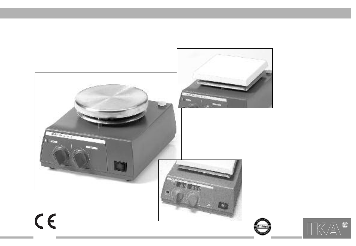
IKA® RH basic 2
IKA® RH basic KT/C
IKA® RH digital KT/C
IKA RH basic 2
IKA RH basic KT/C
BETRIEBSANLEITUNG D 3
OPERATING INSTRUCTIONS GB 11
MODE D’EMPLOI F 19
RH b2dKT0410
IKA RH digital KT/C
Reg.-No. 4343-01
Page 2

CE-KONFORMITÄTSERKLÄRUNG D
Wir erklären in alleiniger Verantwortung, daß dieses Produkt den Bestimmungen der
Richtlinien 89/336/EG; 92/31/EG und 73/23EG entspricht und mit den folgenden
norminativen Dokumenten übereinstimmt: EN 61010-1 (IEC/CEI 61010-1) und EN 61326-1 (IEC
61326-1).
CE-DECLARATION OF CONFORMITY GB
We declare under our sole responsibility that this product corrosponds to the regulations
89/336/EEC; 92/31/EEC and 73/23EEC and conforms with the standards or standardized documents
EN 61010-1 (IEC/CEI 61010-1) and EN 61326-1 (IEC 61326-1).
DÉCLARATION DE CONFORMITÉ CE F
Nous déclarons sous notre propre responsabilité que se produit est conforme aux réglementations 89/336/CEE; 92/31/CEE et 73/23CEE et en conformité avec les normes ou documents
normalisés suivant
EN 61010-1 (IEC/CEI 61010-1) et EN 61326-1 (IEC 61326-1).
Normen und
Gewährleistung
Sie haben ein Original IKA-Laborgerät erworben, das in Technik und
Qualität höchsten Ansprüchen gerecht wird.
Entsprechend den IKA - Verkaufs- und Lieferbedingungen beträgt
die Garantiezeit 24 Monate. Im Garantiefall wenden Sie sich bitte
an Ihren Fachhändler. Sie können aber auch das Gerät unter
Beifügung der Lieferrechnung und Nennung der
Reklamationsgründe direkt an unser Werk senden. Frachtkosten
gehen zu Ihren Lasten.
Warranty
IKA WERKE Janke & Kunkel GmbH & CO. KG
Staufen, Dezember 2003
You have purchased an original IKA laboratory machine which
meets the highest engineering and quality standards.
In accordance with IKA guarantee conditions, the guarantee period is 24 months. For claims under the guarantee please contact
your local dealer. You may also send the machine direct to our
works, enclosing the delivery invoice and giving reasons for the
claim. You will be liable for freight costs.
Garantie
Vous avez fait l’acquisition d’un appareil de laboratoire de conception origi nale IKA, qui répond aux exigences les plus élevées de
technique et de qualité.
Conformément aux conditions de garantie IKA, la durée de garantie s’élève à 24 mois. En cas de recours en garantie, veuillez vous
adresser à votre fournisseur spécialisé. Vous pouvez également
envoyer directement l’appareil à notre usine en joignant votre facture et l’exposé des motifs de réclamation. Les frais d’expédition
sont à votre charge.
2
RH b2dKT
Page 3
RH b2dKT
Inhaltsverzeichnis
Seite
Gewährleistung 2
Sicherheitshinweise 3
Bestimmungsgemäßer Gebrauch 4
Auspacken 4
Inbetriebnahme 4
Einschalten 4
Funktion Rühren 5
Funktion Heizen 5
Sicherheitstemperaturbegrenzung 6
Einstellen der Sicherheitstemperatur “Safe Temp”
Regelung der Mediumstemperatur mit ETC 1
oder Kontaktthermometer (Vers. KT) 7
Error Meldungen 8
Montage - Stativstab H 16 V 8
Wartung und Reinigung 8
Zubehör 9
Technische Daten 10
Ersatzteilliste RH basic 2 / RH basic KT/C / RH digital KT/C
Ersatzteilbild RH basic 2 / RH basic KT/C / RH digital KT/C
(Vers. KT) 6
28
29-31
Sicherheitshinweise
Der IKA RH basic 2; RH basic KT/C und RH digital KT/C wurde
nicht für den Betrieb in gefährlichen Atmosphären, zum Mischen
von Gefahrstoffen und für den Betrieb unter Wasser konstruiert.
Das Gerät darf nicht in explosionsgefährdeten Räumen betrieben
werden. Das Gerät ist auf eine feuerfeste bzw. nicht brennbare
Aufstellfläche zu stellen.
Achtung - Magnetismus! Auswirkungen des Magnetfeldes sind
zu beachten (Herzschrittmacher, Datenträger... ).
Stellen Sie sicher, daß das Netzkabel die Heizplatte nicht berührt!
Das Netzkabel darf nur durch ein gleichwertiges Kabel ersetzt werden.
Version RH basic KT/C und RH digital KT/C: Überprüfen Sie
regelmäßig (wir empfehlen alle 4 Wochen) die Funktion des
Sicherheitstemperaturbegrenzers. Hierzu muss die Sicherheitstemperatur um mindestens 1/4 Umdrehung von dem bereits eingestellten Wert verändert werden und die Einstellung wie unter
Einstellen der Sicherheitstemperaturbegrenzung “Safe Temp”
beschrieben durchgeführt werden. Durch das Überschreiten der
eingestellten Sicherheitstemperatur (z.B. Drehknopf “Temp” auf
Rechtsanschlag gestellt) können Sie die Funktion überprüfen. Die
“Temp” Signalleuchte muss erlöschen und die Heizung muss bleibend ausgeschaltet sein.
Bei Verwendung von PTFE-ummantelten Magnetstäbchen ist folgendes zu beachten: Chemische Reaktionen von PTFE treten ein
im Kontakt mit geschmolzenen oder gelösten Alkali- und
Erdalkalimetallen, sowie mit feinteiligen Pulvern von Metallen aus
der 2. und 3. Gruppe Periodensystems bei Temperaturen über 300400°C.
Nur elementares Fluor, Chlortrifluorid und Alkalimetalle greifen es
an, Halogenkohlenwasserstoffe wirken reversibel quellend.
Quelle: Römpps Chemie-Lexikon und „Ullmann“ Bd.19
Vorsicht beim Berühren der Gehäuseteile und der
Heizplatte!
Verbrennungsgefahr!
Die Heizplatte kann über 300°C heiß werden.
Beachten Sie eine eventuelle Gefährdung durch das Freiwerden
von toxischen (giftigen) oder brennbaren Gasen, die vom erwärmten Material herrühren.
Achten Sie vor Inbetriebnahme darauf, dass der Drehknopf zur
Drehzahlverstellung auf Linksanschlag steht, da das Gerät mit der
zuletzt eingestellten Drehzahl zu laufen beginnt.
Nach einer Unterbrechung der Stromzufuhr während eines Heizoder Rührvorganges läuft das Gerät von selbst wieder an.
Transportieren Sie das Gerät wegen erhöhter Temperatur des
Gehäuses nur im ausgeschalteten und abgekühlten Zustand.
Das Gerät darf nicht am Stativstab H16V oder am Netzkabel transportiert werden.
3
Page 4
Infolge der Materialausdehnung beim Erwärmen und Abkühlen der
Heizplatte kann es zu Knackgeräuschen kommen.
Achtung: Mit diesem Gerät dürfen nur Medien bearbeitet bzw.
erhitzt werden, deren Flammpunkt über der eingestellten Sicherheitstemperaturbegrenzung liegt (max. 400°C für RH basic 2,
100°C bis max. 400°C für RH basic KT/C und RH digital KT/C).
Beachten Sie die einschlägigen Sicherheitshinweise und Richtlinien, sowie Arbeitsschutz- und Unfallverhütungsvorschriften für den
Einsatz im Labor und tragen sie ihre persönliche Schutzausrüstung.
Das Gerät darf nur von einer Fachkraft geöffnet werden.
Verwenden Sie nur Original IKA-Zubehör.
Bestimmungsgemäßer Gebrauch
Der Magnetrührer IKA RH basic 2; RH basic KT/C und RH digital
KT/C ist ein Rührgerät mit Heizfunktion. Seinen Einsatz findet er in
Laboratorien, zum Beispiel in der chemischen Industrie, Schulen
und Apotheken. Das Gerät eignet sich zum Temperieren von
Substanzen, die in Gefäßen auf die Heizplatte gestellt werden. Der
eingebaute Rührantrieb ermöglicht das gleichzeitige Rühren der
Substanzen mit Hilfe eines im Gefäß befindlichen Magnetstäbchens. Die Mischintensität ist abhängig von der Motordrehzahl und
der Größe des Magnetstäbchens. Der RH basic KT/C und RH digital KT/C besitzt zusätzlich einen Kontaktthermometeranschluss
nach DIN 12878 sowie einen einstellbaren Sicherheitskreis.
Auspacken
Bitte packen Sie das Gerät vorsichtig aus und achten Sie auf
Beschädigungen. Es ist wichtig, dass eventuelle Transportschä-den
schon beim Auspacken erkannt werden. Gegebenenfalls ist eine
sofortige Tatbestandsaufnahme erforderlich (Post, Bahn oder
4
Spedition).
Zum Lieferumfang des Gerätes gehören:
Ein RH basic 2, RH basic KT/C oder RH digital KT/C und eine
Betriebsanleitung.
Inbetriebnahme
Überprüfen Sie, ob die auf dem Typenschild angegebene Spannung mit der verfügbaren Netzspannung übereinstimmt. Die verwendete Steckdose muß geerdet sein (Schutzleiterkontakt). Stellen Sie vor dem Einschalten des Gerätes die beiden Drehknöpfe
auf Linksanschlag. Wenn diese Bedingungen erfüllt sind, ist das
Gerät nach Einstecken des Netzsteckers betriebsbereit. Andernfalls ist sicherer Betrieb nicht gewährleistet oder das Gerät kann
beschädigt werden. Beachten Sie die in den Technischen Daten
angegebenen Umgebungsbedingungen (Temperatur, Feuchte).
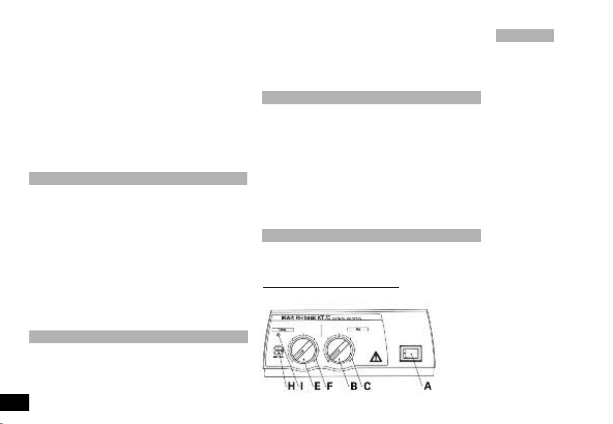
Einschalten
Die Funktionen Heizen und Rühren werden durch Betätigen des
Geräteschalters (A) ein- und ausgeschaltet.
Version RH basic 2 und RH basic KT/C:
bzw. der eingeschaltete Zustand des Gerätes werden durch das
Die Betriebsbereitschaft
Leuchten
der grünen
Kontroll-
leuchte
im
Geräte-
schalter
angezeigt.
RH b2dKT
Page 5
RH b2dKT
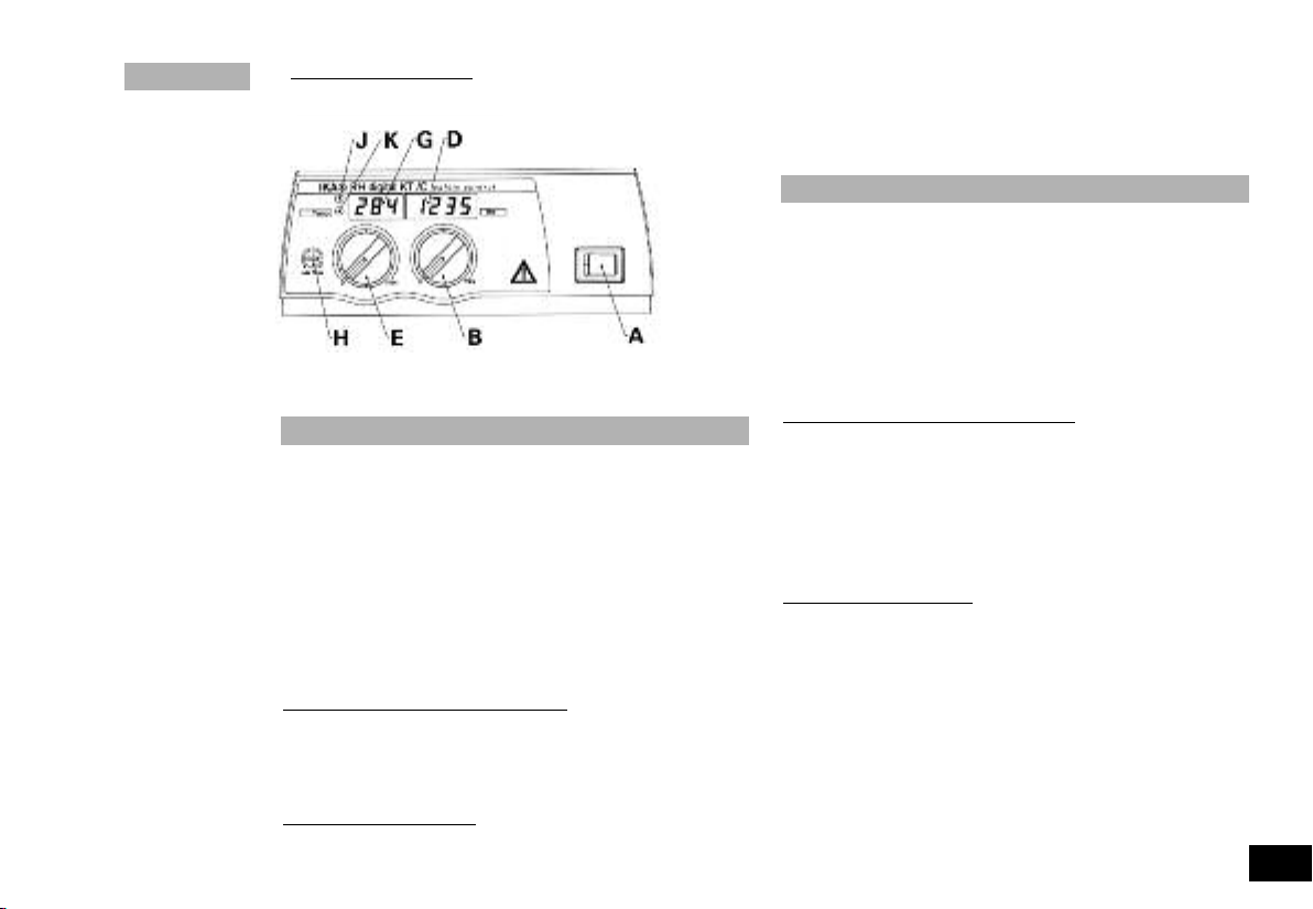
Version RH digital KT/C: Die Betriebsbereitschaft bzw. der ein-
geschaltete Zustand des Gerätes werden durch die LED-Anzei-
gen (D; G) signalisiert. Nach
Einschalten
des Gerätes
leuchten zur
Selbstprü-
fung alle
Segmente
der LED-
Anzeigen
kurz auf.
Funktion Rühren
Das Rührstäbchen im Becherglas, max. 60mm lang, wird von
einem Permanentmagneten angetrieben, der sich dicht unter der
Aufstell- bzw. Heizfläche befindet, die für magnetische Feldlinien
durchlässig ist. Der Permanentmagnet ist direkt auf der
Abtriebswelle des Motors befestigt.
Die tatsächliche Drehzahl ist last- und spannungsabhängig.
Beachten Sie, dass Schwankungen der Netzspannung innerhalb
der zulässigen Toleranz und prozessbedingte Änderungen der Viskosität des zu rührenden Mediums auch geringe Schwankungen
der Drehzahl bewirken.
Version RH basic 2 und RH basic KT/C:
wird am Drehknopf “Mot” (B) mit der dazugehörigen Skala 0 bis 6
(C) eingestellt. Der Skalenwert 0 bis 6 entspricht etwa 0 bis 2000
1/min. Die maximale Drehzahl von 2000 1/min ergibt sich bei
Rechtsanschlag des Drehknopfes im Leerlauf.
Version RH digital KT/C:
Drehknopf “Mot” (B) mit der dazugehörigen Skala 0 bis max. ein-
Die Drehzahl des Motors wird am
Die Drehzahl des Motors
gestellt. Die Drehzahl des Motors wird in der LED-Anzeige (D)
angezeigt. Im Stillstand wird der Wert “0” angezeigt, im Betrieb
die tatsächliche Drehzahl zwischen 100 und 2000 1/min.
Funktion Heizen
Die Heizplattentemperatur des Gerätes wird von dem Regelkreis
konstant gehalten. Der dafür erforderliche Temperatursensor (ein
Thermoelement) ist in der Heizplatte eingebaut.
Das Gerät RH basic 2 hat eine Edelstahlheizplatte mit 400 Watt
Heizleistung.
Die Geräte RH basic KT/C und RH digital KT/C haben eine mit
technischem Email beschichtete Edelstahlheizplatte mit 500 Watt
Heizleistung.
Version RH basic 2 und RH basic KT/C: Am Drehknopf „Temp“
(E) mit der dazugehörigen Skala 0 bis 6 (F) wird die Temperatur der
Heizplatte eingestellt. Der Skalenwert 0 bis 6 entspricht etwa
Raumtemperatur bis max. 320 °C. In Stellung 0 heizt das Gerät bei
normaler Raumtemperatur nicht.
Während der Heizphase leuchtet die Signalleuchte (I) orange auf.
(Orange = Zufuhr von Energie an die Heizplatte; Signalleuchte aus
= keine Energiezufuhr).
Version RH digital KT/C:
Temperatur der Heizplatte eingestellt. Bei einer Änderung der
Stellung des Drehknopfes zeigt die LED-Anzeige (G) die eingestellte SOLL-Temperatur; dabei leuchtet die Signalleuchte (K) auf.
Nach etwa drei Sekunden wechselt die LED-Anzeige auf die ISTTemperatur zurück, die Signalleuchte (K) erlischt.
Die Temperaturanzeige wechselt nun ständig zwischen
Isttemperatur (25 sec) und Solltemperatur (5 sec).
Nach Auswahl der SOLL-Temperatur ist im Heizbetrieb die
Signalleuchte (K) aus und die LED-Anzeige (G) stellt die ISTTemperatur der Heizplatte im Bereich von 0°C bis +320°C dar.
Am Drehknopf „Temp“ (E) wird die
5
Page 6
Während der Heizphase leuchtet die Signalleuchte (J) rot auf. (Rot
= Zufuhr von Energie an die Heizplatte; Signalleuchte aus = keine
Energiezufuhr).
In Stellung “0” heizt das Gerät bei Raumtemperatur nicht.
Ist jedoch die Temperatur der Heizplatte höher als 50°C, zeigt die
LED-Anzeige (G) blinkend den Hinweis “Hot” an.
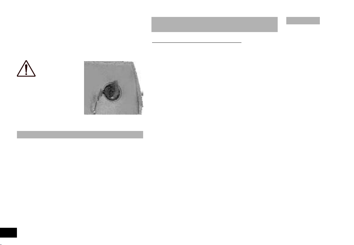
ACHTUNG:
Die Heizplatte
der Version
RH basic KT/C und
RH digital KT/C erwärmt sich
nur, wenn der Kontaktstecker
gesteckt ist (der Kontaktstecker
ist am Gerät unverlierbar befestigt) oder ein Kontaktther-
mometer angeschlossen ist.
Sicherheitstemperaturbegrenzung
Mit der Sicherheitstemperaturbegrenzung lässt sich die maximale
Heizplattentemperatur (Sicherheitstemperatur) einstellen. Damit
wird gewährleistet, dass die Temperatur der Heizplatte den
Flammpunkt des Mediums nicht überschreitet. Der einzustellende
Wert muss experimentell ermittelt werden und sollte in der Regel
etwa 20K unter dem Flammpunkt des Mediums liegen.
Das Gerät RH basic hat einen festeingestellten Sicherheitskreis,
der die Heizplattentemperatur auf 400°C begrenzt.
Bei den Geräten RH basic KT/C und RH digital KT/C ist der
Sicherheitskreis einstellbar. Die maximale Heizplattentemperatur
lässt sich auf einen Bereich von 100°C bis max. 400°C einstellen.
6
Einstellen der Sicherheitstemperatur
“Safe Temp” (Vers. KT)
Version RH basic KT/C und RH digital KT/C: Die Stellschraube
“Safe Temp” (H) befindet sich links neben dem Drehknopf “Temp”
(E) auf der Bedienfront.
Mit der Stellschraube „Safe Temp“ (H) des Sicherheitstemperaturbegrenzers wird die gewünschte Sicherheitstemperatur eingestellt. Sobald die gewünschte Sicherheitstemperatur von einer
höher eingestellten Solltemperatur überschritten wird, oder ein
Defekt des Temperaturreglers auftritt, schaltet die Heizung in diesem Zustand bleibend ab, die Rührfunktion läuft mit der vor der
Störung eingestellten Drehzahl weiter.
• Drehen Sie mit einem Schlitzschraubendreher die Stellschraube
“Safe Temp” (H) auf Rechtsanschlag.
• Drehen Sie die Stellschraube nicht über den Links- bzw.
Rechtsanschlag hinaus, da in diesem Falle das Poti zerstört wird.
• Stellen Sie mit dem Drehknopf “Temp” (E) die Solltemperatur
auf die gewünschte Sicherheitstemperatur (”Safe Temp”) ein und
warten Sie, bis diese erreicht ist.
• Drehen Sie die Stellschraube “Safe Temp” (H) langsam nach
links, bis die Heizfunktion abschaltet und die Signalleuchte (I bzw.
J) erlischt.Schaltet sich die Signalleuchte (I bzw. J) innerhalb die-
ser Zeit wieder an, müssen Sie den Vorgang wiederholen und die
Stellschraube “Safe Temp” (H) erneut wieder langsam nach links
drehen.
Die Sicherheitstemperatur ist korrekt eingestellt, wenn die
Signalleuchte (I bzw. J) nicht innerhalb einer Minute wieder aufleuchtet.
• Drehen Sie danach die Stellschraube “Safe Temp” (H) wieder
geringfügig nach rechts.
• Nach erneutem Aus- und Wiedereinschalten mit dem Geräteschalter (A), ist das Gerät betriebsbereit.
HINWEIS: Wenn die Stellschraube “Safe Temp” (H) auf min.
(Linksanschlag) gestellt wird, ist die Heizung ausgeschaltet.
RH b2dKT
Page 7

Das Ansprechen des Sicherheitskreises wird angezeigt durch
Version RH basic 2 und RH basic KT/C: das Blinken der Signalleuchte (I) etwa zwei Mal je Sekunde (Hinweis: Durch das regelmäßige Blinken kann das Ansprechen des Sicherheitskreises vom
normalen Heizzyklus unterschieden werden).
Version RH digital KT/C:
Anzeige (G).
Regelung
der Mediumstemperatur
die Darstellung von “-S-” in der LED-
mit Kontaktthermometer
Die Regelung der Mediumstemperatur mit Kontaktthermometer
ist zu bevorzugen. Man erhält damit nach Einstellung der
Solltemperatur eine kurze Aufheizzeit, praktisch keine
Temperaturdrift und eine geringe Temperaturwelligkeit.
An der Rückseite des Gerätes befindet sich die Diodenbuchse zum
Anschluß des Kontaktthermometers oder zum Einstecken des
Kontaktsteckers.
Die Elektronik des Gerätes liefert einen Prüfstrom, der über die
Steckerstifte 3 und 5 der Diodenbuchse fließen muß, damit die
Heizplatte heizt.
Sicherheitskontaktthermometer
nach DIN 12 878 Klasse 2 oder nach Gerstel werden mit einem
3-adrigen Kabel angeschlossen, der Prüfstrom fließt durch das
Kontaktthermometer.
Sicherheitsfunktion:
Wird der Prüfstrom z.B. durch Bruch des Kontaktthermometers
oder Herausfallen des Kabelsteckers unterbrochen, schaltet die
Heizung ab.
Kontaktthermometer ohne Sicherheitskreis
nach DIN 12 878 Klasse 0. Das Gerät heizt nur, wenn der
Prüfstromkreis durch eine elektrische Verbindung der
Steckerstifte 3 und 5 geschlossen ist.
2-adrige Anschlußkabel:
Steckerstifte 3 und 5 des geräteseitigen Steckers miteinander
verbinden.
3-adrige Anschlußkabel:
Hier kann der Prüfstromkreis auch im Anschlußkopf des
Kontaktthermometers hergestellt werden (Steckerstift 2 und 3
miteinander verbinden). - Sicherheitsvorteil!
Am Kontaktthermometer wird die Solltemperatur mit dem dreh-
baren Magnetknopf eingestellt, wobei als Bezugspunkt die
Oberkante der Wandermutter auf der Sollwertskala gilt. Am Temp-
Drehknopf des Gerätes wird die erforderliche Ober-flächentem-
peratur der Heizplatte vorgewählt.
Stellt man den Temp-Drehknopf auf die maximal einstellbare
Temperatur, ergibt sich zwar das schnellstmögliche Aufheizen, die
Mediumstemperatur schwingt jedoch über den am Kontaktthermometer eingestellten Sollwert.
Stellt man den Temp-Drehknopf ungefähr auf den doppelten
Sollwert, ergibt sich ein guter Kompromiß zwischen schnellem
Aufheizen und Überschwingen.
Stellt man den Temp-Drehknopf exakt auf die Solltemperatur,
erreicht das Medium die Solltemperatur nicht, da immer etwas
Wärmegefälle zwischen Heizplatte und Medium auftritt.
Am ETS-D wird die Solltemperatur eingestellt.
Bei Verwendung eines ETS-D4 empfiehlt es sich, bei höheren
Mediumstemperaturen den ETS-D4 im On/Off-Modus (ZweiPunkt-Regelung) zu verwenden.
RH b2dKT
7
Page 8
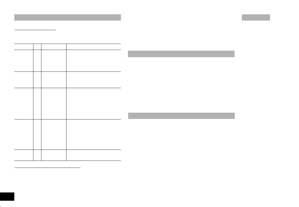
Error - Meldungen
Version RH digital KT/C:
Treten am Gerät Störungen auf, werden diese blinkend in der LEDAnzeige (G bzw. D) dargestellt:
Fehlercode
E 2 G zu hohe Innen- Gerät ausschalten und abkühlen
- S - G Ansprechen Verringern der Solltemperatur
E 2 D keine Impulse Gerät ausschalten und Antrieb
E 6 G Kontaktstecker Kontaktstecker stecken
andere Gerät ausschalten, reinigen und
Version RH basic 2
Eine Störung wird durch das Blinken der Signalleuchte (I) angezeigt. Bitte versuchen Sie zur Behebung der Störungsursache folgende Maßnahmen:
• Gerät ausschalten und abkühlen lassen.
LED Ursache Maßnahme
temperatur lassen. Sicherstellen, dass bo-
denseitige Lüftungsöffnungen
nicht verschlossen sind.
des Sicher- bzw. gegebenenfalls erneutes
heitskreises Einstellen des Sicherheitskreises
an der Lesega- auf äußere Ursache für Blockierbel (Defekt Le- rung untersuchen. Ist keine äussegabel oder sere Ursache feststellbar, Gerät
Motor, Motor reinigen und zur Reparatur
blockiert) geben
nicht gesteckt
Bruch bzw. Kontaktthermometer ausKurzschluss- tauschen
des Kontaktthermometers
zur Reparatur geben.
und RH basic KT/C:
8
• Äußere Ursachen, die zur Störung führen können, beseitigen.
(Kontaktstecker oder Kontaktthermometer stecken)
• Gerät erneut einschalten.
Tritt der Fehler weiterhin auf, geben Sie das Gerät bitte gereinigt
zur Reparatur.
Montage - Stativstab H 16 V
Der Stativstab H 16 V kann wie nachstehend beschrieben in das
Gewinde rechts hinten am Gehäuse eingeschraubt werden:
• Kunststoffkappe und Scheibe von der Stativstange entfernen
und die Sechskantmutter abschrauben
• Scheibe und Sechskantmutter auf den Gewindeansatz am
Gehäuse legen und festhalten
• Stativstab in die Mutter und das Gewinde des Gehäuses ein-
schrauben und Sechskantmutter kontern
Wartung und Reinigung
Der IKA RH basic 2; RH basic KT/C oder RH digital KT/C arbeitet
wartungsfrei. Er unterliegt lediglich der natürlichen Alterung der
Bauteile und deren statistischer Ausfallrate.
Bei Ersatzteilbestellungen geben Sie bitte die auf dem Typenschild angegebene Fabrikationsnummer, den Gerätetyp sowie
die Positiosnummer und die Bezeichnung des Ersatzteiles an.
Bitte senden Sie nur Geräte zur Reparatur ein, die gereinigt und
frei von gesundheitsgefährdenden Stoffen sind. Reinigen Sie IKAGeräte nur mit von IKA freigegebenen Reinigungsmittel.
Verwenden Sie zum Reinigen von:
Farbstoffen Isopropanol
Baustoffen Tensidhaltiges Wasser/Isopropanol
Kosmetika Tensidhaltiges Wasser/Isopropanol
RH b2dKT
Page 9

Nahrungsmittel Tensidhaltiges Wasser
Brennstoffen Tensidhaltiges Wasser
Bei nicht genannten Stoffen fragen Sie bitte bei IKA nach. Tragen
Sie zum Reinigen der Geräte Schutzhandschuhe. Elektrische
Geräte dürfen zu Reinigungszwecken nicht in das Reinigungsmittel gelegt werden. Bevor eine andere als die vom Hersteller empfohlene Reinigungs- oder Dekontaminierungsmethode angewandt
wird, hat sich der Benutzer beim Hersteller zu vergewissern, daß
die vorgesehene Methode das Gerät nicht zerstört.
Version RH basic KT/C und RH digital KT/C:
Pflege- und Wartungshinweise zur Heizplatte mit technischer
Emailbeschichtung
Die technische Emailschicht macht die Heizplatte pflegeleichter
und widerstandsfähiger gegen Säuren und Laugen. Die Heizplatte
wird dadurch aber auch anfälliger auf extreme Temperatur-schwankungen und Anstoßen, was zur Folge haben kann, dass die
Beschichtung abplatzt oder springt.
Achten sie deshalb darauf, dass der Boden des Aufstellgefäs-ses
eben, sauber und trocken ist; der Boden des Aufstellge-fässes darf
keine scharfen Rillen, Ränder oder Kanten aufweisen. Eine regelmäßige Reinigung der Heizplatte wird dringend empfohlen.
Zubehör
RS 1 Rührstäbchenset H 16V Stativstab
H 15 Badaufsatz RSE Rührstäbchenentferner
Nur Vers. KT
H 36 Haltestange ETC 1 IKATRON
H 44 Kreuzmuffe ETS-D IKATRON
Empfohlene IKA-Rührstäbchen
TRIKA-Rührstab PTFE, dreieckig 55mm lang
IKAFLON-Rührstäbe PTFE
ø 8mm Längen 25, 30, 40 und 50 mm
RH b2dKT
9
Page 10
Technische Daten
RH basic 2 RH basic KT/C RH digital KT/C
Bemessungsspannung: VAC 220 - 240 ±10% 220 - 240 ±10% 220 - 240 ±10%
oder VAC 115 ±10% 115 ±10% 115 ±10%
oder VAC 100 ±10% 100 ±10% 100 ±10%
Frequenz: Hz 50/60 50/60 50/60
Motorleistungsaufnahme W 15 15 15
Motorleistungsabgabe W 22 2
Drehzahlbereich: rpm 100 bis 2000 100 bis 2000 100 bis 2000
stufenlos einstellbar stufenlos einstellbar stufenlos einstellbar
Drehzahleinstellung: Drehknopf frontseitig Drehknopf frontseitig Drehknopf frontseitig
Drehzahlanzeige: Skala 0 - 6 Skala 0 - 6 4stellige LED-Anzeige (0 - 2000 1/min)
Antrieb: Spaltpolmotor Spaltpolmotor Spaltpolmotor
Max. Rührmenge (Wasser): ltr 10 15 15
Heizplatte Werkstoff: 1.4301 1.4301 m. Emailbeschichtung 1.4301 m. Emailbeschichtung
Heizplatten-Abmessung: mm Ø 125 130 x 130 130 x 130
Heizleistung: W 400 (230VAC) 500 (230VAC) 500 (230VAC)
W 400 (115VAC) 500 (115VAC) 500 (115VAC)
W 360 (100VAC) 450 (100VAC) 450 (100VAC)
Temperaturbereich: °C RT ......... 320 RT ......... 320 RT ......... 320
Temperatureinstellung: Drehknopf frontseitig Drehknopf frontseitig Drehknopf frontseitig
Temperaturanzeige: Skala 0 - 6 Skala 0 - 6 4stellige LED-Anzeige (0°C - +320°C)
Kontaktthermometeranschluß: --------- nach DIN 12 878 nach DIN 12 878
Einstellbarer Sicherheitskreis: °C --------- 100 ....400 100 ....400
Festeingest. Sicherheitskreis: °C 400 --------- --------Zul. Umgebungstemperatur: °C +5 bis +40 +5 bis +40 +5 bis +40
Zul. relative Feuchte: % 80 80 80
Zul. Einschaltdauer: % 100 100 100
Funkentstörung: nach VDE 0871 nach VDE 0871 nach VDE 0871
Schutzart nach DIN 60529: IP 21 IP 21 IP 21
Verschmutzungsgrad: 22 2
Überspannungskategorie: II II II
Schutzklasse: 1(Schutzerde) 1(Schutzerde) 1(Schutzerde)
Sicherung: A 10AT Id-Nr. 2755400 10AT Id-Nr. 2755400 10AT Id-Nr. 2755400
Geräteeinsatz über NN: m max. 2000 max. 2000 max. 2000
Abmessungen: mm 168 x 220 x 105 168 x 220 x 105 168 x 220 x 105
Gewicht: kg 2,4 2,4 2,4
10
RH b2dKT
Page 11

RH b2dKT
Contens
Page
Warranty 2
Safety instructions 11
Proper use 12
Unpacking 12
Commisioning 12
Starting 12
Function stirring 13
Function heating 13
Limiter of safety temperature 14
Adjusting the Safety Temperature limit
Controlling the Medium Temperature via ETC 1
or Contact Thermometer (Vers. KT) 15
Error messages 16
Mounting - Support H 16 V 16
Maintenance and cleaning 16
Accessories 17
Technical data 18
Listofspare parts RH basic 2 / RH basic KT/C / RH digital KT/C
Spare parts diagram RH basic 2 / RH basic KT/C / RH digital KT/C
“Safe Temp” (Vers. KT) 14
28
29-31
Safety instructions
The IKA RH basic 2; RH basic KT/C or RH digital KT/C
constructed for operations in dangerous atmospheres, for
mixing dangerous substances or for operation under water.
The instrument may not be operated in rooms with explosion
hazard. Furthermore, it has to be placed upon a fire-proof
and/or not burnable surface.
Attention - Magnetism! Effects of the magnetic field have to be
taken into account (e.g. data carriers, cardiatic pacemakers ... ).
Please make sure that the mains cable does not contact the
heating plate.
equal quality and capacity.
The power cable must be replaced by a cable of
was not
Version RH basic KT/C and RH digital KT/C:
(we recommend every 4 weeks) the function of the safety temperature limiter. For this the safety temperature must be changed around at least 1/4 revolution of the value already stopped
and be accomplished the attitude as under “adjusting the safety
temperature delimitation SAFE temp” decribed. By the exceeding of the adjusted safety temperature (e.g. rotary button
“temp” posed on right end stop) you can examine the function.
The “temp” pilot lamp must expire and the heating must be
lasting switched off.
When using PTFE-coated magnetic bars, the following hase to
be noted:
molten or dissolved alkaline and alkaline - earth metals, as well as
with fine-particled powders of metals of the 2. and 3. group of the
periodical system at temperatures abo ve 300-400°C. Only elementary fluorine, chlorine trifluoride und alkaline metals do attack
PTFE, halogen hydrocarbons have a reversibly swelling effect.
Please consider possible endangering due to release of toxid or
flamable gaser caused by heated medium.
Before placing the device in service, please ensure that the turn
dial for adjusting the speed is against the left stop, since the device will begin to run at the last speed that was set.
After an interruption in the power supply during an agitation procedure, the device will start running again by itself.
Because of increased temperature of the housing, you should only
move the unit when it has been turned off and has cooled down.
The instrument may not be
or on the connection line.
Chemical reactions of PTFE occur in contact with
Source: Römpps Chemie-Lexikon and „Ullmann“ Bd.19
Exercise caution when touching the housing parts
and the heating plate!
Risk of burns! The heating plate
can reach temperatures in excess of 300°C.
transported on a H 16 V support rod
Examine regularly
11
Page 12

Clicking noises may occur as a result of material expansion
during heating and cooling.
Caution: Only process and heat up any media that has a flash
point higher than the adjusted safety temperature limit (max
400°C for RH basic 2, 100°C to max. 400°C for RH basic KT/C and
RH digitall KT/C.
Please observe the relevant safety information and guidlines as
well as work protection and accident prevention requirements for
use in the laboratory.
Only a specialist may open the device.
Use only original IKA accessories.
Proper use
The IKA RH basic 2; RH KT; RH basic KT/C or the IKA RH digital KT/C is a stirring instrument with heating function. It is used
in e.g. laboratories of the chemical industry, in scools as well
as in pharmacies. The instrument is suitable for tempering substaces which are placed on the heating plate in vessels. By
means of a built-in stirring drive and with the help of a magnetic bar within the vessel, the substances can be stirred at the
same time. The mixing intensity is dependent on the motor
speed and on the size of the magnetic bar. The Der RH basic
KT/C and RH digital KT/C also has a contact thermometer
connection in compliance with requirements of DIN 12 878 and
an adjustable safety circuit.
Unpacking
during transport are ascertained when unpacking. If applicable a
fact report must be set immediately (post, rail or forwarder).
The delivery scope covers: an RH basic 2 / RH basic KT/C or RH
digital KT/C and operating instructions.
Commissioning
Check whether the voltage specified on the type plate matches
the mains voltage available. The power socket used must be earthed (protective earth conductor contact). Before tuning on the
machine, adjust the turn dial for controlling the spped so that it is
against the left stop. If these conditions are met, the device is
ready to operate after plugging in the mains plug. If these procedures are not followed, safe operation cannot be guaranteed
and/or the equipment may be damaged.
Observe the ambient conditions (temperature, humidity, etc.)
listed under Technical Data.
Starting
The heating stirring features can be turned on and off by pressing
the unit switch A).
Version RH basic 2
tion and turned on states of the device are indicated by the
and RH basic KT/C: The ready for opera-
green
lamp in
the unit
switch
lighting
up.
Please unpack the equipment carefully and check for any
ges. It is important that any damages which may have arisen
12
dama-
RH b2dKT
Page 13

RH b2dKT
Version RH digital KT/C: When you switch on the stirrer it will
run a self-test and all the LED segments of the displays will light
up for a
few
seconds.
After this,
the LED’s
(D; G) light
up to indicate that
the unit is
powered
up and
ready for
operation.
Function Stirring
The stirring rod in the glass beaker with a maximum lenght of
60mm is driven by a permanent magnet located directly under the
placing and heating surface. It allows magnetic field lines to pass
trough it. The permanent magnet is fastened directly onto the drive
shaft of the motor.
The actual speed depends on the load and voltage. Note that fluctuations in the in the mains power voltage within the allowable
tolerance and changes in viscosity of the materials to be stirred
resulting from processes they undergo may also cause minor fluctuations in the speed.
Version RH basic 2
can be adjusted on the “Mot” dial (B) with a scale from 0 to 6 (C).
The scale values from 0 to 6 on this dial correspond roughly to
speeds ranging from 0 to 2000 rpms. The maximum speed of
2000 rpms is reached when the dial switch is turned all the way to
the right and there is no load on the motor.
Version RH digital KT/C:
knob (B); the knob has a graduated scale from to maximum rpm.
and RH basic KT/C: The speed of the motor
Set the motor speed using the “Mot”
The motor speed is shown on the LED display (D). When the
motor is stopped the speed “0” will be displayed. When the motor
is operating, the display will show the current speed in the range
100 to 2000 rpm.
Function Heating
The temperature of the heating plate of the instrument is kept constant by a control circuit. In addition, it is monitored by a safety circuit. The required temperature sensor (a thermo-couple) is installed in the heating plate. The RH basic unit has a stainless steel surface plate with a heating output of 400Watt.
RH basic KT/C and RH digital KT/C units have a enamel-coated
stainless steel surface plate with a heating output of 500 Watt.
Version RH basic und RH basic KT/C:
heating plate can be adjusted on the „Temp“ turn dial (E) with a
corresponding scale from 0 to 6 (F). The scale values from 0 to 6
correpond approximately to area temperatures up to a max. of 320
°C. When the setting is at 0, the device does not heat the medium
up at normal room temperature.
During the heating phase, the signal light (I) lights up orange (orange = power is being supplied to the heating plate; signal light off
= no power being supplied)
Version RH digital KT/C:
can be adjusted on the „Temp“ turn dial. When you change the
knob setting, the LED display (G) will the show the SETPOINT
temperature and the warning light (K) will light up. After approx. 3
seconds the LED display will switch back to showing the ACTUAL
temperature and the warning light (K) will switch off.
The temperature indication now constantly changes between
actual temperature (25 sec) and target temperature (5 sec).
When you select the SETPOINT temperature and as the unit heats
up, the warning light (K) will remain off and the LED display (G)
will show the ACTUAL temperature of the surface plate in the
range from 0°C to +320°C.
The temperature of the heating plate
The temperature of the
13
Page 14

The red warning light (J) will light up while heating is in progress.
(Red warning light ON = surface plate heating power supply is ON;
red warning light OFF = surface plate heating power is OFF).
PLEASE NOTE!
The haeting plate of
the version RH basic
KT/C and RH digital KT/C only
heats up, if the contact plug
has been plugged (the contact
plug is undetachably fitted to the
instrument), or if an ETC 1 and/or
a contact thermometer has
been connected.
Limiter of safety temperature
The safety temperature limiter makes it possible to adjust the
maximum temperature of the heating plate (safety temperature).
This ensures that the temperature of heating plate does not
exceed the flame point of the material. The value to be set must
be determined by trial and error and should generally fall about 20K
below the flame point of the medium.
RH basic 2 devices have a safety circuit with a fixed setting that
limits the temperature of a heating plate to 400°C.
RH basic KT/C and RH digital KT/C devices have an adjustable
safety circuit. The maximum temperature of the heating plate can
be adjusted within a range from 100°C to max. 400°C.
14
Adjusting the safety temperature
limit “Safe Temp” (Vers. KT)
Version RH basic KT/C and RH digital KT/C: RH basic KT/C and
RH digital KT/C versions: The ”Safe Temp” set screw (H) is to the
left of the ”Temp” knob (E) on the front operator panel.
You can use the „Safe Temp“ set screw (H) of the safety tempe-
rature limiter to adjust the desired safety temperature. If the desired safety temperature is exceeded by a higher adjusted target
temperature, of if there is a defect in the instrument controller, the
heating turns off permanently in this state and the stirring func-
tion continues to run at the speed that was set prior to the
malfunction.
• Using a straight-edge screwdriver, turn the “Safe Temp” adjustment screw (H) as far as it will go clockwise (to the right).
• Do not turn the screw beyond the natural right or left limit of
rotation, as this will destroy the potentiometer.
• Use the “Temp” turn dial (E) to adjust the set-point temperature to desired safety temperature (”Safe Temp”).
• Turn the “Safe Temp” set screw (H) slowly to the left until the
heating function switches off and the signal light (I or J) goes off.
Wait for about one more minute to ensure that the signal light ( F
) going off does not merely indicate the end of a switching cycle of
the heater. If the signal light (I or J) turns on again within this time,
you must repeat the procedure, slowly turning the “Safe Temp”
(H) adjustment screw to the left again.
When the signal light (I or J) does not light up again within one
minute, the safety temperature is correctly set.
• After this, turn set “Safe Temp” adjustment screw (H) back
slightly to the right (clockwise).
• After you have turned the unit switch (A) of and back on again,
the device is ready for operatin.
NOTE: When the “Safe Temp” (H) adjustment screw is set to
the minimum level (as far as it will go to the left) the heating function is turned off.
RH b2dKT
Page 15

Triggeringof the safety circuit is shown in the following ways:
On RH basic 2 and RH basic KT/C versions: the warning light (I)
will flash two times per second. (Note: regular flashing indicates
that the safety circuit has been triggered; this warning light
remains permanently lit to indicate that a standard heating cycle is
in progress).
On the RH digital KT/C version: the letter ”-S-” will be shown on
the LED display (G).
Controlling
the Medium Temperature
via ETC 1 or Contact Thermometer
The control of the medium temperature via ETC 1 or contact-thermometer should be preferred. Its advantages are: just a short heating-up phase after setting the rated temperature, practically no
temperature drift and only a minor temperature waviness.
The rear of the instrument houses the diode bushing for connection the ETS-D or contact thermometer, or for plugging the contact
plug.
The elektronics of the instrument supply a test current that
has to flow over plug pins 3 and 5 of the diode bushing in
order for the heating plate to heat.
Safety contact thermometers
acc. to DIN 12 878 class 2 or acc. Gerstel are connected with a
three-wire cable, the test current flows through the contact thermometer.
Safety function:
If the test current is interrupted because of e.g. breakage of contact
thermometer or falling out of the cable plug, the heating cuts off.
Conact thermometer without safety circuit
acc. to DIN 12 878 class 0. The instrument only heats if the test
current circuit is closed by an electrical connection of the plug
pins 3 and 5.
2-wire connecting cables:
Connect plug pins 3 and 5 of the instrument plug.
3-wire connecting cables:
Here the test current circuit can also be produced in the terminal
head of the contact thermometer (connect plug pins 2 and 3).
A 3-wire cable with the required bridge is available (accessories).
The rated temperature is set on the contact thermometer by
means of the rotary magnetic head, whereby the upper edge of
the traveling nut is the reference point on the rated value scale.
The required surface temperature of the heating plat is presel-
ected on the temp-rotary knob of the instrument.
If the temp-rotary knob is set to the maximally adjustable temperature, the heating-up takes place as rapidly as possible, yet the
medium temperature overshoots the rated value set on the
contact thermometer.
If the temp-rotary knob is set to twice the rated value, the result
is good compromise between rapid heating-up and overshooting.
If the temp-rotary knob is set precisely to the rated temperature,
the medium does not reach the rated temperature owing to a drop
in temperature between heating plate and medium.
The rated temperature is seting on the ETS-D.
If you are using an ETS-D4, we recommend using the ETS-D4 in
On/Off mode (two-point control) at higher medium temperatures.
RH b2dKT
15
Page 16

Error - Messages
Version RH digital KT/C:
The LED displays (C and D) will start to flash and display a code
when a fault is present. The fault codes and troubleshooting procedure are as follows:
Fault code
E 2 G Inner tempera- Switch off the unit and allow it
- S - G Safety circuit Reduce the temperature setpoint
E 2 D
E6 G
Other Switch off the unit. Clean and
Version RH basic 2
The warning light (I) flashes to indicate that a fault is present. To
remove a fault condition, proceed as follows:
LED Cause Solution
ture too high cool down. Check that the venti-
is triggered or reset the safety circuit where
No pulse to the
reading fork external cause blocking the
(faulty reading stirring drive. If you cannot find
fork, faulty and visible cause, clean the unit
motor or sei- and return it for repair.
zed motor)
Not put contact
plug
Break and/or exchange the contact
short-circuit thermometer
of the contactthermometers
codes return for repair.
and RH basic KT/C:
lation slots on the bottom are not
blocked and that cooling air can
circulate freely.
necessary.
Switch off the unit. Trace the
Contact plugs put
• Switch off the unit and allow it to cool down.
• Trace and remove the cause of the fault.
• Switch on the unit.
If the fault persists, clean the unit and return it for repair.
Mounting - Support rod H 16 V
The H 16 V support rod can be screwed into the threading on the
right behind the housing as follows:
• Remove the plastic cap and washer from the support rod and
screw off the hex nut.
• Place the washer and hex nut on the beginning of the threa-
ding on the housing and hold them in place.
• Screw the support rod into the nut and threading of the hou-
sing and counter-tighten the hex nut.
Maintenance and Cleaning
The IKA RH basic 2; RH basic KT/C or RH digital KT/C is maintenace-free. It is subject only to the natural wear and tear of components and their statistical failure rate.
When ordering spare parts, please give the manufacturing
number shown on the type plate, the machine type and the
name of the spare part.
Please send in equipment for repair only after it has been cleaned
and is free from any materials which may constitute a health
hazard. Use only cleansing agents which have been approved by
IKA to clean IKA devices. To remove use:
Dyes isopropyl alcohol
Construction materials
Cosmetics
Foodstuffs water containing tenside
Fuels water containing tenside
water containing tenside / isopropyl alcohol
water containing tenside / isopropyl alcohol
16
RH b2dKT
Page 17

For materials which are not listed, please request information from
IKA. Wear the proper protective gloves during cleaning of the devices. Electrical devices may not be placed in the cleansing agent for
the purpose of cleaning.
Before using another than the recommended method for cleaning
or decontamination, the user must ascertain with the manufacturer that this method does not destroy the instrument.
Version RH basic KT/C
Information for Care and Maintenance of the HeatingPlate with
Technical Enamel Coating
The technical enamel makes the heating plate easier to care fort
and more resistant to acids and bases. Because of it, however,
theheating plate is also more susceptible to extreme fluctuations
in temperature and the force of impact. This can result in cracks
forming or the coating flaking off.
Make certain that the bottom of the placing vessel is even, clean
and dry. The bottom of the placing vessel must not have any sharp
grooves, sides or edges. Remove residues of bases and immedialety. We recommend most strongly that you clean the heating
plate regularly.
and RH digital KT/C
Accessories
RS 1 set of stirring bars H16V support rod
H 15 bath top
Vers. KT
H 36 holding rod
H 44 cross sleeve
Recommended IKA-stirres
TRIKA-stirrer PTFE, triangular, length 55mm
IKAFLON-stirrers PTFE
dia 8mm lengths 25, 30, 40 and 50 mm
RSE PTFE stirring bar remover
ETC 1 IKATRON
ETS-D IKATRON
RH b2dKT
17
Page 18

Technical data
RH basic 2 RH basic KT/C RH digital KT/C
design voltage: VAC 220 - 240 ±10% 220 - 240 ±10% 220 - 240 ±10%
or VAC 115 ±10% 115 ±10% 115 ±10%
or VAC 100 ±10% 100 ±10% 100 ±10%
design frequency: Hz 50/60 50/60 50/60
motor power consumption: W 15 15 15
motor power output: W 22 2
speed range: rpm 100 to 2000 100 to 2000 100 to 2000
infinitely variable setting infinitely variable setting infinitely variable setting
adjustment of the speed control: rotary knob on the front rotary knob on the front rotary knob on the front
display of the speed control: scala 0 - 6 scala 0 - 6 LED-display four digit (0 - 2000 rpm)
motor: shaped pole motor shaped pole motor shaped pole motor
max. stirring volume (water): ltr 10 15 15
heating plate: 1.4301 1.4301 with enamal coating 1.4301 with enamal coating
heating plate dimensions: mm Ø 125 130 x 130 130 x 130
heating power: W 400 (230VAC) 500 (230VAC) 500 (230VAC)
W 400 (115VAC) 500 (115VAC) 500 (115VAC)
W 360 (100VAC) 450 (100VAC) 450 (100VAC)
temperature range: °C RT ......... 320 RT ......... 320 RT ......... 320
temperature setting: rotary knob on the front rotary knob on the front rotary knob on the front
temperature display: scala 0 - 6 scala 0 - 6 LED-display four digit (0°C - +320°C)
contact thermometer connection: --------- DIN 12 878 DIN 12 878
infinitely variable safe temperature: °C --------- 100 ....400 100 ....400
fixed adjustment safe temperature: °C 400 --------- --------perm. ambient temperature: °C +5 to +40 +5 to +40 +5 to +40
perm. humidity: % 80 80 80
perm. on time: % 100 100 100
screened for radio interference: under VDE 0871 under VDE 0871 under VDE 0871
protection to DIN 60529: IP 21 IP 21 IP 21
contamination level: 22 2
overvoltage categorie: II II II
protection class : 1(protective earth) 1(protective earth) 1(protective earth)
fuse: A 10AT Id-Nr. 2755400 10AT Id-Nr. 2755400 10AT Id-Nr. 2755400
operation at a terrestrial altitude: m max. 2000 above sea level max. 2000 above sea level max. 2000 above sea level
dimensions: mm 168 x 220 x 105 168 x 220 x 105 168 x 220 x 105
weight: kg 2,4 2,4 2,4
18
RH b2dKT
Page 19

RH b2dKT
Sommaire
Page
Garantie 2
Conseils de sécurité 19
Utilisation conforme 20
Déballage 20
Mise en service 20
Mise en marche 20
Fonction agitation 21
Fonction chauffage 21
Limitation par température de sécurité 22
Réglage de la limite de température de
Réglage de la température du milieuavec ETC 1
ou avec un thermomètre de contact (Vers. KT) 23
Messages d’erreur 24
Montage - Tige support H 16 V 24
Entretien et nettoyage 24
Accessoires 25
Caractéristiques techniques 26
Liste de pièces de rechange
Pièces de rechange
sécurité “Safe Temp” (Vers. KT) 22
RH basic 2 / RH basic KT/C / RH digital KT/C
RH basic 2 / RH basic KT/C / RH digital KT/C
28
29-31
Conseils de sécurité
Le IKA RH basic 2; RH basic KT/C et RH digital KT/C n’a pas été conçu
pour un fonctionnement sous atmosphére dangereuse, pour le mélange
de matériaux gangereux, ni pour une utilisation immergée. Ne pas utiliser l’appareil dans des locaux exposés àdes risques d’explosion. Placer
l’appareil sur une surface en matériau réfractaire ou inflammable.
Attention - Magnétisme! Attention aux effets du champ magnétique ( par ex. supports d’informations, stimulateurs cardiaques ).
Veiller à ce que le cordon d’alimentation secteur ne soit pas en
contact avec la plaque chauffante! Utiliser impérativement un cordon de même type en cas de remplacement.
Version RH basic KT/C et RH digital KT/C: Réexaminez régulièrement (nous recommandons toutes les 4 semaines) la fonction
du limiteur de température de sécurité. Pour cela la température
de sécurité doit être modifiée autour d’au moins 1/4 rotations de
la valeur déjà prête doit être modifiée et le réglage comme sous
“ajuster de la limitation de température de sécurité SAFE
température” décrits mis en oeuvre. Par le franchissement de la
température de sécurité prête (p.ex. bouton rotatif “température”
placé sur max.), vous pouvez réexaminer la fonction. La “température” Lampe de signalisation doit expire et le chauffage doit être
mis hors circuit durablement.
En cas d’utilisation de barreaux aimantés enrobés de PTFE, prendre garde au fait que, à des températures supérieures à 300-400°c,
les métaux alcalins et alcalino-terreux fondusou dissous, ainsi que
les métaux sous forme de poudre fine appartenant aux groupes 2
et 3 de la classification périodique des éléments, réagissent au
contact du PTFE. Seuls le fluor élémentaire, le trifluorure de chlore
et les métaux alcalins attaquent le PTFE; les hydrocaebures halogénés produisent un effet de gonflement reversible.
Source: Römpps Chemie-Lexikon et „Ullmann“ Bd.19
Faites attention quand vous touchez les pièces du
boîtier et la plaque chauffante !
Risques de brûlures !
La plaque chauffante peut atteindre des tempéra -
tures allant jusqu'à plus de 300°C.
Veuillez prendre en considération un danger éventuel provoqué par
des gaz toxique ou inflammables d’s au rechauffement du produit.
Vérifiez avant la mise en service que le bouton de réglage de la
vitesse soit bien en butée à gauche. En effet, l’appareil utilise
toujours la dernière vitesse sélectionnée.
Après une interruption de l’alimentation pendant le chauffage ou l’agitation, l’appareil se remet en route tout seul. En raison de la
température élevée du boîtier pendant le service, transportez l’appareil seulement une fois éteint et refroidi. L’appareil n’a pas le droit
d’être transporté par la tige support H16V ou par le câble secteur.
19
Page 20

En raison de la dilatation des matériaux lors du chauffage et du
refroidissement de la plaque chauffante, des craquements peuvent se faire entendre.
Attention: Traiter et chauffer avec cet appareil uniquement des produits dont le point éclair est supérieur à la température limite de
sécurité choisie. Voir données tecniques pour la température limite de sécurité (max. 400°C pour RH basic 2, 100°C à au max.
400°C pour RH basic KT/C et RH digital KT/C)
Veuillez observer les consignes de sécurité et directives applicables,
de même que les prescriptions relatives à la protection du travail et
‘a la prévention des accidents en cas d’utilisation au laboratoire.
Seul un technicien est habilité à ouvrir l’appareil.
N’utilisez que des accessoires IKA d’origine.
Utilisation conforme
L'agitateur magnétique RH basic 2; RH basic KT/C ou RH digital
KT/C est un appareil d'agita tion possédant une fonction de
chauffage. Il est utilisé dans les laboratoires, par exemple dans
l'industrie chimique, les écoles et les pharmacies. Cet appareil est
adapté pour mettre en équilibre thermique des substances
placées dans des récipients sur la plaque chauffante.
L'entraînement d'agitation intégré permet en même temps
d'agiter les substances à l'aide d'un agitateur magnétique se
trouvant dans le récipient. La force de l'agitation dépend de la
vitesse du moteur et de la taille de l'agitateur magnétique.
L’agitateur RH basic KT/C et RH digital KT/C est en plus équipé
d’une prise pour thermomètre de contact suivant DIN 12 878 et
d’un circuit de sécurité réglable.
Il est important de constater les éventuels dommages dus au
transport dès le déballage. Le cas échéant, établir immédiatement
un constat correspondant (poste, chemins de fer ou transporteur).
Le IKAMAG RH basic 2; RH basic KT/C ou RH digital KT/C est livré
avec son mode d'emploi.
Mise en service
Vérifiez si la tension indiquée sur la plaque signalétique correspond
bien à la tension du secteur. La prise de courant utilisée doit être
mise à la terre (conducteur de protection).
Si ces conditions sont remplies, l'appareil est prêt à fonctionner
dès qu'il est branché sur le secteur. Dans le cas contraire, le parfait fonctionnement n'est pas garanti ou l'appareil peut être
endommagé.
Veuillez respecter les paramètres d'utilisation indiqués dans les
données techniques (température, taux d'humidité).
Mise en marche
Les fonctions “chauffage” et “agitation” sont activées/désactivées
par actionnement de l’interrupteur (A).
Version RH basic 2
Lorsque l’appareil est sous tension/en service, le voyant vert de
et RH basic KT/C:
l’interrupteur est
allumé.
Déballage
Déballez l'appareil avec précaution et vérifiez s'il est en parfait état.
20
RH b2dKT
Page 21

RH b2dKT
Version RH digital KT/C:
ment de l’appareil est signalisé par l’affichage DEL (D; G). Après
L’état de disponibilité ou de foncttionne-
avoir allumé
l ’ a p p a r e i l ,
tous les segments de
l’affich ag e
DEL s’allument brièvement afin de
s ’ a s s u e r
qu’ils fonctionnement.
Fonction agitation
Le baguette d’une longueur max. de 60mm, placée dans le récipient, est entraînée par un aimant permanent sous la surface d’installation/de chauffage et près de cette surface laissant passer les
lignes de champ magnétiques. L’aimant permanent est directement fixé sur l’arbre de sortie du moteur.
La vitesse de rotation réelle dépend de la charge et de tension.
Tenez compte du fait que des variations de la tension secteur à
l’intérieur de la plage de tolérance et des modifications process de
la viscosité de la substance agitée entraînent aussi de faibles variations de la vitesse de rotation.
Version RH basic
réglé à l’aide du potentiomètre “Mot” (B) et de l’échelle 0 - 6 (C)
associée. Les valeur 0 à 6 correspondent à une plage de rotation
de 0 à 2000 tr/mn. La vitesse maximale de 2000 tr/mn s’obtient
dans le cas d’une marche à vide lorsqu’on tourne le potentiomètre jusqu’à la butée droite.
Version RH digital KT/C:
le bouton rotatif “Mot” (B) qui dispose d’une échelle allant de 0 à
et RH basic KT/C: Le régime du moteur est
Pour régler la vitesse du moteur, utiliser
max. La vitesse du moteur apparaît dans l’affichage DEL (D). A
l’arrêt, la valeur “0” apparaît, en marche, la vitesse réelle entre
100 et 2000 1/min est affichée.
Fonction chauffage
Grâce à un système de régulation, la température de la plaque
chauffante est maintenue constante. La sonde nécessaire - un
thermoélément - est encastrée dans la plaque chauffante.
L’appareil RH basic 2 est équipé d’une plaque chauffante en acier
inox d’une puissance de chauffage de 400 Watts.
Les appareils RH basic KT/C et RH digital KT/C sont équipés
d’une plaque chauffante en acier inox, avec un revêtement en
émail, d’une puissance de chauffage de 500 Watts.
Version RH basic 2 und RH basic KT/C:
„Temp“ (E) et l’échelle 0 - 6 (F) associée permettent de régler la
température de la plaque chauffante. L’échelle 0 - 6 fournit une
température max. de 320 °C. En position 0, l’appareil ne chauffe
pas en cas de température ambiente normale.
Pendant le chauffage, le voyant (I) émet une lumière orange (orange = alimentation de la plaque chauffante; voyant éteint = pas d’alimentation).
Version RH digital KT/C:
tent de régler la température de la plaque chauffante. Lors de la
modification du réglage du bouton rotatif, l’affichage DEL (G) indique la température de consigne définie; le témoin de signalisation
(K) s’éteint alors. Après environ trois secondes, l’affichage DEL
revient sur la température réelle, le témoin de signalisation (K) s’al-
lume.
L’indication de température change maintenant constamment entre
une température (25 sec) et une température de cible (5 sec).
En mode de chauffage, le témoin de signalisation (K) est éteint
une fois que la température de consigne est choisie et l’affichage
DEL (G) indique la température réelle de la plaque chauffante dans
La potentiomètre „Temp“ (E) permet-
La potentiomètre
21
Page 22

une plage allant de 0°C à +320°C.
Pendant la phase de chauffage, le témoin de signalisation (J) est
allumé en rouge. (Rouge = apport d’énergie à la plaque chauffante; témoin de signalisation éteint = pas d’apport d’énergie).
ATTENTION:
La plaque chauffante (Vers. RH
basic KT/C et RH
digital KT/C) ne
chauffe que si la prise de
contact est enfichée (elle est
livrée, fixée à l’appareil) ou si un
ETC 1 ou un thermomètre de
contact est connecté.
Limitation par température de sécurité
Cette fonction permet de régler la température maximale
(température de sécurité) de la plaque chauffante de manière qu’elle ne dépasse pas le point d’ignition du millieu. La
valeur réglée doit être déterminée par des expériences et
se situer environ 20K en dessous du point dìgnition du
milieu.
Les modèles RH basic 2 ont un circuit de sécurité à réglage fixe,
la température de la plaque chauffage étant limitée à 400°C.
Sur les appareils RH basic KT/C et RH digital KT/C, le circuit
de sécurité est réglable. La température maximale de la plaque chauffante peut être réglée entre 100°C et 400°C.
Réglage de la limite de température
de sécurité “Safe Temp” (Vers. KT)
Version RH basic KT/C et RH digital KT/C: La vis de réglage
“Safe Temp” (H) se trouve à gauche à côté du bouton rotatif
“Temp” (E) sur le panneau de commande.
La vis „Safe Temp“ (H) du limiteur permet de régler la température de sécurité sur la valeur requise. Dès qu’une température de
consigne supérieure dépasse cette valeur ou que le thermostat
présente un dysfonctionnement, le chauffage s’arrête dans cet
état. L’agitation continue à la vitesse de rotation r´glée avant la
perturbation.
• Tournez avec un tournevis pour vis à fente la vis “Safe Temp” (H)
jusqu’à la butée droite.
• Ne tournez pas la vis de réglage au-delà de la butée gauche ou
droite sinon la potentiom`tre sera endommagé.
• Réglez avec le bouton “Temp” (E) la température de consigne
sur la température de sécurité requise (”Safe Temp”).
• Tournez la vis de réglage “Safe Temp” (H) lentement à gauche
jusqu’à ce que la fonction Chauffage soit désactivée et que le
témoin (I ou J) n’ait pas signalé la fin d’un cycle de commande du
chauffage. Si le témoin (I ou J) s’allume de nouveau durant cet
intervalle, répétez l’opertion et tournez la vis “Safe Temp” (H) de
nouveau lentement à gauche.
La température de sécurité est correctement réglée quand le
témoin (I ou J) ne s’allume plus en l’espace d’une minute.
• Tournez ensuite la vis “Safe Temp” de nouveau légèrement à
droite.
• L’appareil est opérationnel après avoir été éteint puis rallumé
avec l’interrupteur (A).
22
REMARQUE: Quand la vis “Safe Temp” (H) est réglée sur
min. (butée gauche) le chauffage est éteint.
RH b2dKT
Page 23

L’identification du circuit de sécurité est indiqué par:
Version RH basic et RH basic KT/C: le clignotement du témoin
de signalisation (I) environ deux fois par seconde (Remarque: Le
clignotement régulier permet de différencier l’identification du circuit de sécurité du cycle de chauffage normal).
Version RH digital KT/C:
(G).
l’indication “-S-” dans l’affichage DEL
Réglage de la température du millieu
avec ETC 1 ou thermomêtre de
contact (Vers. KT)
Il est préférable de régler la température du milieu avec un ETC 1
ou un thermomètre de contact. On obtient ainsi après affichage de
la température de consigne un court temps de chauffage, pratiquement aucune dérive de température et une faible oscillation
de la tempérture.
Au dos de l’appareil se trouve la fiche à broches pour le branchement du ETC 1, du thermomètre de contact ou pour enficher la
prise de contact. (voir illustration 2)
L’électronique de l’appareil fournit un courant d’essai qui circule au niveau des pôles (broches) 3 et 5 de la fiche à b roches
afin que la plaque chauffe.
Thermomètre de contact de sécurité
selon DIN 12 878, classe 2 ou selon Gerstel est connectéavec un câble 3 fils, le courant d’essai circule dans le thermomèter de contact.
Fonction securité:
Le chauffage cesse si le courant d’essai est interrompu; par
exemple si le thermomètre ce casse ou si la prise se débranche.
Thermomètre de contact sans circuit de sécurité
selon DIN 12 878 classe 0. L’appareil ne chauffe que si les
pôles 3 et 5 du circuit du courant d’essai sont reliés électriquement.
Câble 2 fils:
relier entre elles les broches 3 et 5 de la prise située sur la
partie latérale.
Câble 3 fils:
Dans ce cas, le circuit du courant d’essai peut être crée dans la
tâte du thermomètre de contact (relier entre elles les broches 2
et 3). Avantage au niveau de la sécurité!
Un câble 3 fils avec la liaison nécessaire est disponible (accessoire).
La température de consigne est choisie avec la tête
magnétique du thermomètre de contact sachant que cette
températur est donnée par la partie supérieure de la vis sans
fin sur la graduation. Avec le potentiomètre de température
on doit présélectionner la température de la plaque chauf-
fante.
Si l’on affiche la température maximale avec le potentiomètre
de température, on obtient certes la montée en température la
plus rapide mais la température du milieu dépasse alors la
température de consigne affichée au thermomètre de contact.
Si l’on régle le potentiomètre à la même température que la
température de consigne, lemilieu n’atteint janais cette dernière car il y a un gradient de température entre la plaque chauffante et le milieu.
Le température de consigne doit être réglée sur l’ETS-D.
En cas de travail avec ETS-D4, il est recommandé d’utiliser
celui-ci en mode On/Off (régulation à 2 points) si la température du milieu est élevée.
RH b2dKT
23
Page 24

Messages d’erreur
Version RH digital KT/C:
Si des avaries surviennent dans l’appareil, elles sont indiquées par
un clignotement au niveau de l’affichage DEL (C ou D):
Code erreur
E 2 C Température Eteindre l’appareil et le laisser re-
- S - C Indication du Réduire la température de con-
E 2 D
E 6 G Pas prise de Des prises de courant de
autres
DEL Cause Messure
intérieure trop froidir. S’assurer que les ouvertuélevée res de ventilation latérales au sol
circuit de sécu- signe ou, si nécessaire, régler le
rité circuit de sécurité à nouveau.
Pas d’impulsion
de la fourchette
de lecture (panne
de la fourchette
de lecture ou du
moteur, moteur
bloqué)
courant de contact mettent
contact mise
Coupure et/ou Des thermomètres de contact
court-circuit échanger
du thermomètre de
contact
ne sont pas obstruées.
Eteindre l’appareil et contrôler qu’il
n’y a pas de causes deblocage
dans l’entraînement. Si aucun
cause externe ne peut être définie,
nettoyer l’appareil et le donner
à un service de réparation
Eteindre l’appareil, le nettoyer et le
donner à un service de réparation.
24
Version RH basic 2 et RH basic KT/C:
Une avarie est indiquée par le clignotement du témoin de signali-
sation (I) angezeigt. Afin de tenter de remédier à la cause de l’avarie, veuillez mettre en oeuvre les mesures suivantes:
• Eteindre l’appareil et le laisser refroidir.
• Eliminer les causes externes qui peuvent causer l’avarie.
• Redémarrer l’appareil.
Si l’erreurréapparaît, veuillez nettoyer làppareil et le donner à un
service de réparation.
Montage - Tige support H 16 V
La tige support H 16 V peut être vissée dans le filetage sur la
face arrière du boîtier, à droite:
• Retirez le capuchon en plastique et la rondelle de la tige, et
dévissez l’écrou à six pans.
• Posez la rondelle et l’écrou sur l’extrémité du filetage du
boîtier et tenez-les.
• Vissez la tige dans l’écrou et le filetage du boîtier. Bloquez
l’écrou six pans.
Entretien et nettoyage
Le fonctionnement de les RH basic, RH basic KT/C ou RH digital
KT/C ne nécessite pas d’entretien. Il est simplement soumis au
vieillissement naturel des pièces et à leur taux de défaillances statistique. Lors de la commande de pièces de rechange, veuillez
indiquer le numéro de fabrication figurant sur la plaque d’identification, le type de l’appareil et la désignation de la pièce
de rechange. Nous vous prions de n’envoyer en réparation que les
appareils qui ont été nettoyés et sont exempts de matières nocives pour la santé. Ne nettoyer les appareils IKA qu'avec les produits de nettoyage autorisés par IKA.
RH b2dKT
Page 25

Nettoyage de:
substances colorantes avec isopropanol
substances de construction eau + tensioactif / isopropanol
cosmétiques eau + tensioactif / isopropanol
produits alimentaires eau + tensioactif
Combustibles eau + tensioactif
Pour les substances non citées ici, contacter IKA. Veiller à porter
des gants pour le nettoyage. Ne pas placer les appareils électriques dans le produit de nettoyage.
Avant d’employer une méthode de nettoyage ou décontamination
autre que celle conseillée par le constructeur, l’utilisateur est tenu
de s’informer auprès du constructeur que la méthode prévue ne
détruit pas l’appareil.
Vers. C
Consignes d’entretien et de maintenance pour la plaque
chauffante à revètement émail technique
Le revètement émail techniqie facilite l’entretien de la plaque et
augmente sa résistance aux acides et solutions. Il rend cependant
la plaque aussi plus sensible à des variations de température ou
chocs extrêmes, qui peuvent provoquer des fissures ou en éclatement du revêtement.
Veillez par conséquent toujours à ce que le socle du récipient soit
plan, propre et sec. Le socle ne doit pas présenter de rainures, arêtes ou bords vifs. Enlevez immédiatement les restes d’acide et de
solution. Il est vivement recommandé de nettoyer la plaque régulièrement.
Accessoires
RS 1 Jeu de baquettes H16V Tige support
d’agitation
H 15 Accessoires de bain RSE Outil d’enlèvement des
baquettes d’agitation
Vers. KT
H 36 Barre de fixation ETC 1 IKATRON
H 44 Noix de serrage ETS-D IKATRON
Baquettes d’agitation IKA conseilléen
Tige d’agitation TRIKA en PTFE, triangulaire; Longueur 55 mm
Tige d’agitation IKAFLON en PTFE
ø 8mm Longueurs 25, 30, 40 et 50 mm
RH b2dKT
25
Page 26

Caractéristiques techniques
RH basic 2 RH basic KT/C RH digital KT/C
Tension nominale: VAC 220 - 240 ±10% 220 - 240 ±10% 220 - 240 ±10%
ou VAC 115 ±10% 115 ±10% 115 ±10%
ou VAC 100 ±10% 100 ±10% 100 ±10%
Fréquence: Hz 50/60 50/60 50/60
Puissance consommée moteur: W 15 15 15
Puissance fournie moteur: W 22 2
Gamme de vitesse: 1/min de 100 à 2000 de 100 à 2000 de 100 à 2000
règlable sans intervalles règlable sans intervalles règlable sans intervalles
Règlage gamme de vitesse: Bouton frontale Bouton frontale Bouton frontale
Affichage de vitesse: échelle 0 - 6 échelle 0 - 6 à quatre chiffres affichage DEL (0 - 20001/min)
Moteur: à pole fedu à pole fedu à pole fedu
Quantité max. agitée (eau): ltr 10 15 15
Plaque chauffante matériau: 1.4301 1.4301 à revètement émail 1.4301 à revètement émail
Plaque chauffante dimensions: mm Ø 125 130 x 130 130 x 130
Puissance de chauffante: W 400 (230VAC) 500 (230VAC) 500 (230VAC)
W 400 (115VAC) 500 (115VAC) 500 (115VAC)
W 360 (100VAC) 450 (100VAC) 450 (100VAC)
Gamme de température: °C RT ......... 320 RT ......... 320 RT ......... 320
Reglage de température: Bouton frontale Bouton frontale Bouton frontale
Affichage de température: échelle 0 - 6 échelle 0 - 6 à quatre chiffres affichage DEL (0°C - +320°C)
Connexion du thermomètre de contact: --------- DIN 12 878 DIN 12 878
Ajustage de sécurité température: °C --------- 100 ....400 100 ....400
Ajustage fixe de sécurité température: °C 400 --------- --------Température environ admissible: °C de +5 à +40 de +5 à +40 de +5 à +40
Taux d’humidité relatif admissible: % 80 80 80
Facteur de service admissible: % 100 100 100
Antiparasitage: selon VDE 0871 selon VDE 0871 selon VDE 0871
Degré protection selon DIN 60529: IP 21 IP 21 IP 21
Degré de pollution: 22 2
Catégorie de surtension: II II II
Clsse de protection: 1(terre de protection) 1(terre de protection) 1(terre de protection)
Fusible: A 10AT Id-Nr. 2755400 10AT Id-Nr. 2755400 10AT Id-Nr. 2755400
Hauteur max. d’utilisation de l’appareil: m 2000 2000 2000
Dimensions: mm 168 x 220 x 105 168 x 220 x 105 168 x 220 x 105
Poids: kg 2,4 2,4 2,4
26
RH b2dKT
Page 27

RH b2dKT
27
Page 28

Ersatzteilliste List of spare parts
Pos. Bezeichnung
7 Senkschraube M4 x16
9 Kombischraube m. 4kt Scheibe
14 Kunststoffscheibe
15 Scheib e A3,2 (Vers. KT/C)
16 Federmutter
17 Federmutter (Vers. KT/C)
18 Federmutter (Vers. KT/C)
19 Federmutter (Vers. KT/C)
24 Abstandshalter LP (Vers. digital KT)
25 Anschlussleitung
26 Zugentlastung
27 Abdeckkappe (Vers. RH basic 2)
27 Kontaktstecker (Vers. KT/C)
28 Stecker 2pol
29 Stecker 3pol
30 Fuß
31 Schraubstopfen
33 Keramikbuchse (Vers. KT/C)
34 Thermoelement (Vers. KT/C)
35 Magnet
36 Drehknopf
37 Poti - Achse (Vers. KT/C)
39 Rohrheizkörper (Vers. RH basic 2)
39 Folienheizung (Vers. KT/C)
40 Isolierung (Vers. KT/C)
45 Frontfolie
46 Warnschild
49 Glasseidenschlauch (Vers. RH basic 2)
51 Gehäuseoberteil
59 Buchse 85 Flachbandleiter vollst. (Vers. digital)
60 Buchse 2001 Motor vollst.
61 Buchse 2002 Thermoelement vollst
62 Buchse 2003 Bodenblech vollst
63 Buchse 3001 Sicherung 6,3A
70 Halteblech
71 Strahlschutzblech
73 Zahnscheibe
74 Fenstereinsatz (Vers. basic 2)
74 Filterfolie (Vers. digital)
75 Wärmeverteilplatte (Vers. RH basic 2)
76 Andrückblech (Vers. RH basic 2)
77 Aufstellplatte (Vers. RH basic 2)
80 Wippschalter
81 BLP Steuerung
82 Aufstellplatte (Vers. KT/C)
83 Andruckblech (Vers. KT/C)
84 BLP Anzeige (Vers. digital)
Item.Designation
7 Countersunk screw M4 x16
9 Screw with washer assembly
14 Plastic washer
15 Washer A3,2 (Vers. KT/C)
16 Spring nut
17 Spring nut (Vers. KT/C)
18 Spring nut (Vers. KT/C)
19 Spring nut (Vers. KT/C)
24 Distance holder LP (Vers. digital KT)
25 Connection line
26 Mains lead cleat
27 Cap (Vers. RH basic 2)
27 Contact plug (Vers. KT/C)
28 Connector 2pol
29 Connector 3pol
30 Base
31 Screwed plug
33 Ceramic bushing (Vers. KT/C)
34 Thermoelement (Vers. KT/C)
35 Magnet
36 Rotary knob
37 Potentiometer arbor (Vers. KT/C)
39 Tubular heating element (Vers. RH basic 2)
39 Foil heating (Vers. KT/C)
40 Insulating (Vers. KT/C)
45 Front foil
46 Danger sign
49 Glass silk hose (Vers. RH basic 2)
51 Housing upper part
59 Bushing 85 Flat-strip lead compl. (Vers. digital)
60 Bushing 2001 Motor compl.
61 Bushing 2002 Thermoelement compl.
62 Bushing 2003 Bottom plate compl.
63 Bushing 3001 Fuse 6,3A
70 Support plate
71 Protection - sheet metal
73 Toothed washer
74 Window employment (Vers. basic 2)
74 Filter foil (Vers. digital)
75 Heat dissipator plate (Vers. RH basic 2)
76 Pressing sheet metal (Vers. RH basic 2)
77 Placing plate (Vers. RH basic 2)
80 Rocker switch
81 PCB control
82 Placing plate (Vers. KT/C)
83 Pressing sheet metal (Vers. KT/C)
84 PCB display (Vers. digital)
28
Liste des pièces de rechange
Réf. Désignation
7 Vis à tête conique M4 x16
9 Boulon avec rondelle incorporée
14 Rondelle plastique
15 Rondelle A3,2 (Vers. KT/C)
16 Écrou à ressort
17 Écrou à ressort (Vers. KT/C)
18 Écrou à ressort (Vers. KT/C)
19 Écrou à ressort (Vers. KT/C)
24 Écarteur LP (Vers. digital KT)
25 Linge de raccordement
26 Décharge de traction
27 Capuchon (Vers. RH basic 2)
27 Brise de contact (Vers. KT/C)
28 Fiche 2pol
29 Fiche 3pol
30 Pied
31 Bouchon mâle fileté
33 Douille céramique (Vers. KT/C)
34 Thermocouple (Vers. KT/C)
35 Aimant
36 Bouton de réglage
37 Axe potentiomètre (Vers. KT/C)
39 Radiateur tubulaire (Vers. RH basic 2)
39 Chauffage de feuille (Vers. KT/C)
40 Isolation (Vers. KT/C)
45 Feuille frontale
46 Signal de danger
49 Tuyau de verre textile (Vers. RH basic 2)
51 Partie supérieur de boîtier
59 Douille 85 Conducteur à ruban compl. (Vers. digital)
60 Douille 2001 Moteur compl.
61 Douille 2002 Thermocouple compl.
62 Douille 2003 Tôle de fond compl.
63 Douille 3001 Fusible 6,3A
70 Tôle de stop
71 Déflecteur
73 Roue dentée
74 Insertion de fenètre (Vers. basic 2)
74 Feuille de filtre (Vers. digital)
75 Plaque conductrice de la chaleur (Vers. RH basic 2)
76 Tôle de pression (Vers. RH basic 2)
77 Plaque de composants (Vers. RH basic 2)
80 Interrupteur à bascule
81 Unité de commande à plaque imprimée
82 Plaque de composants (Vers. KT/C)
83 Tôle de pression (Vers. KT/C)
84 Unité de affichage à plaque imprimée (Vers. digital)
RH b2dKT
Page 29

0
L N
9
3001
27
25
26
28
29
83
71
51
33607171534351940391882
4546
IKA
®
RH digital KT/C safety control
0max max0
safe temp
30200170732003
63
85
84
24
74
62
61
62
37
36
16
14
81
80
31
Verdrahtungsplan / wire diagram
Schalter / switch
LED-Anzeige
/ LED display
Litzen Farbkennzeichnungf nach IEC 757
strandet conductors colour coding to IEC 757
Erdungswinkel
Gehäuse /
ground connection
housing
Thermoelement / thermoelements
Heizung
/ heating
Motor
/ motor
GNYE
BU
BK
L
N
BU BU
BKBK
1
a
2
a
1
2
M
L
N
++
--
Ersatzteilbild / spare parts diagram / Pièces de rechange RH digital KT/C
RH b2dKT
29
Page 30

0
0
27
IKA
®
RH basic KT/C safety control
Litzen Farbkennzeichnungf nach IEC 757
strandet conductors colour coding to IEC 757
Thermoelement / thermoelements
3
Temp
2
1
4
5
60
0
1
2
3
4
5
6
Mot
safe temp
29
28
51
71
8333607171534351940391882
30200170732003
61
62
62
74
63
37
45 46
31
Verdrahtungsplan / wire diagram
BU
Schalter / switch
BU
++
--
Erdungswinkel
Gehäuse /
ground connection
housing
Heizung
/
heating
Motor
/
motor
BKBK
1a
2
a
1
2
GNYE
BU
BK
L
N
L
N
25
26
9
3001
16
36
14
81
80
L
N
M
Ersatzteilbild / spare parts diagram / Pièces de rechange RH basic KT/C
30
RH b2dKT
Page 31

3
0
0
27
IKA
®
RH basic 2
BU
29
28
26
25
3001
9
V
erdrahtungsplan / wire diagram
Schalter / switch
Temp
2
1
4
5
60
0
1
2
3
4
5
6
Mot
31
4645
49
51
2002
7176757353977
36
16
14
81
80
59
60
61
62
74
63
307020012003
BU
Thermoelemente / thermoelements
++
--
Erdungswinkel
Gehäuse /
ground connection
housing
Heizung
/ heating
Motor
/ motor
BKBK
1a
2
a
1
2
GNYE
BU
BK
L
N
L
N
M
L
N
+ = RD
- = BL
Ersatzteilbild / spare parts diagram / Pièces de rechange RH basic 2
RH b2dKT
31
Page 32

Europe
Middle East
Africa
North America
China
Asia
Australia
IKA®- Werke
GmbH & Co.KG
Janke & Kunkel-Str. 10
D-79219 Staufen
Tel. +49 7633 831-0
Fax +49 7633 831-98
sales@ika.de
www.ika.net
IKA® Works, Inc.
2635 North Chase Pkwy SE
Wilmington NC 28405-7419 USA
Tel. 800 733-3037
Tel. +1 910 452-7059
Fax +1 910 452-7693
usa@ika.net
IKA® Works Guangzhou
173 - 175 Friendship Road
Guangzhou
Economic and Technological
Development District
510730 Guangzhou, China
Tel. +86 20 8222-6771
Fax +86 20 8222-6776
sales@ikagz.com.cn
Japan
IKA® Japan K.K.
3-5-8 Yokonuma-cho,
Higashiosaka-city, Osaka
577-0808 Japan
Tel. +81-6-6730-6781
Fax +81-6-6730-6782
info@ika.ne.jp
India
IKA®India Private Limited
814/475, Survey No. 129/1
Mysore Road, Kengeri
Bangalore - 560 060
Karnataka, India
Tel. +91 80 26253900
Fax +91 80 26253901
info@ika.in
IKA® Works (Asia)
Sdn Bhd
No. 17 & 19, Jalan PJU 3/50
Sunway Damansara
Technology Park
47810 Petaling Jaya
Selangor, Malaysia
Tel. +60 3 7804-3322
Fax +60 3 7804-8940
sales@ika.com.my
Korea
IKA® Korea Co LTD
1710 Anyang Trade Center
1107 Buhung-dong,
Dongan-gu
Anyang City, Kyeonggi-do
Post code: 431-817
South Korea
Tel. +82 31-380-6877
Fax +82 31-380-6878
michael@ikakorea.co.kr
Brasilia
IKA®Works Inc.
Rua São Bento, 701 Sala 1
CEP 13160-000 Centro Artur Nogueira - SP
Brasil, South America
Tel. +55 19 3877 2399
Fax +55 19 3877 2399
fcabral@ika.net
00/0000/1
 Loading...