

Page 1

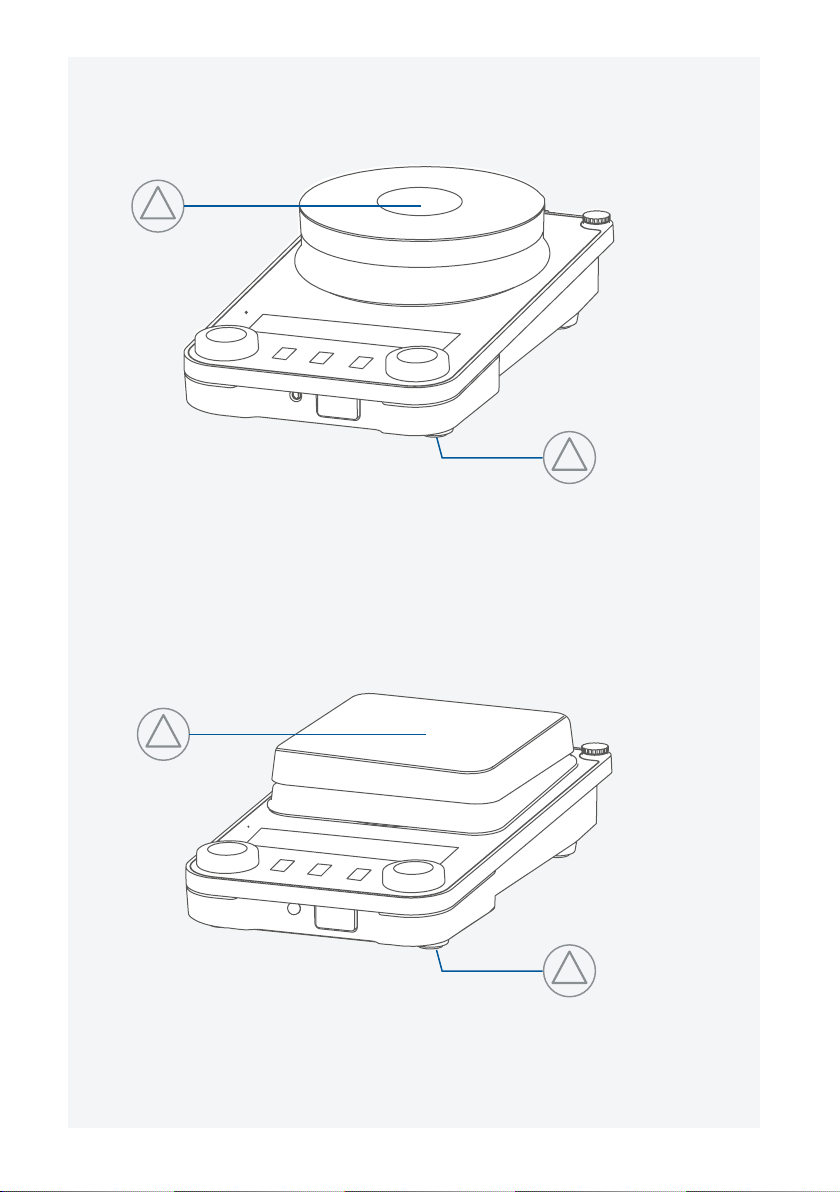
IKA Plate (RCT digital)
RCT 5 digital
Page 2
!
!
!
Fig. 1
!
Page 3

EU Declaration of conformity .............................................................6
Explication of warning symbols ......................................................... 6
Safety instructions ............................................................................. 7
!
Intended use ................................................................................... 10
Unpacking ...................................................................................... 11
Installation ...................................................................................... 12
Operator panel and display ............................................................. 15
Operation ....................................................................................... 17
Interfaces and outputs .................................................................... 29
Maintenance and cleaning .............................................................. 32
Accessories ..................................................................................... 32
Error codes ..................................................................................... 33
Technical Data ................................................................................36
Warranty ........................................................................................ 38
5
Page 4

Source language: German
EU Declaration of conformity
We declare under our sole responsibility that this product corresponds to the directives 2014/35/EU,
2006/42/EC, 2014/30/EU and 2011/65/EU and conforms with the following standards or normative documents: EN 61010-1, EN 61010-2-010, EN 61010-2-051, EN 61326-1, EN 60529
and EN ISO 12100.
A copy of the complete EU Declaration of Conformity can be requested at sales@ika.com.
Explication of warning symbols
/// Warning symbols
Danger!
Warning!
Caution!
Notice!
!
Attention!
Danger!
Indicates an (extremely) hazardous situation, which, if not avoided, will
result in death, serious injury.
Indicates a hazardous situation, which, if not avoided, can result in
death, serious injury.
Indicates a potentially hazardous situation, which, if not avoided, can
result in injury.
Indicates practices which, if not avoided, can result in equipment damage.
Indicates the risks due to magnetism.
Indicates the exposure to a hot surface.
/// General Symbols
Position number
A–––
Indicates device components relevant to actions.
Correct / result
Indicates the correct execution or the result of an action step.
Wrong
Indicates the incorrect execution of an action step.
Note
Indicates steps of actions that require particular attention.
Beep
Indicates action steps, for which beep sounds are to be heard.
6
Page 5

Safety instructions
/// General information
› Read the operating instructions in its entirety before using the device and follow
the safety instructions.
› Keep the operating instructions in a place where it can be accessed by everyone.
› Ensure that only trained staff work with the device.
› Follow the safety instructions, guidelines, occupational health and safety and accident
prevention regulations.
› Electrical outlet must be grounded (protective ground contact).
Attention – Magnetism!
› Effects of the magnetic field have to be taken into account (e.g. data storage media, cardiac
pacemakers ...).
Risk of burns!
› Exercise caution when touching parts of the housing and the heating plate.
› The heating plate can reach dangerous temperatures. Pay attention to the residual heat on
the heating plate after switching off the stirrer.
› The device may only be transported when the heating plate has cooled down.
/// Device design
Danger!
› Do not use the device in explosive atmospheres, it is not EX-protected.
› With substances capable of forming an explosive mixture, appropriate safety measures must
be applied, e.g. working under a fume hood.
› To avoid body injury and property damage, observe the relevant safety and accident
prevention measures when processing hazardous materials.
!
Caution!
› Device surface is partially made of glass:
- Glass surface can be damaged by impact.
- If glass surface is damaged it could cause injury, don`t use the device anymore.
!
Notice!
› Set up the device in a spacious area on an even, stable, clean, non-slip, dry and fireproof
surface.
› The feet of the device must be clean and undamaged.
› Ensure that the power cord set / temperature sensor cable does not touch the heating plate.
› Check the device and accessories for damage before each use. Do not use damaged
components.
/// Permissible medium / contaminants / side reactions
Warning!
› Only process media that will not react dangerously to the extra energy produced through
processing. This also applies to any extra energy produced in other ways, e.g. through light
irradiation.
7
Page 6

› Beware of hazards due to:
- flammable materials,
- combustible media with a low boiling temperature,
- glass breakage,
- incorrect container size,
- overfilling of media,
- unsafe condition of container.
› Process pathogenic materials only in closed vessels under a suitable fume hood.
Caution!
› In unsupervised and safe operation, this device may only handle or heat media whose flash
point is above the set safety temperature limit. The safety temperature limit must always be
set to at least 25 °C lower than the flash point of the media used. (acc. to EN 61010-2-010)
› The heating plate can heat up due to the action of the magnets at high motor speeds, even
if the heater is switched off.
› Please consider any possible contaminations and unwanted chemical reactions.
› It may be possible for wear debris from rotating accessory parts to reach the material being
processed.
› When using PTFE-coated magnetic bars, the following has to be noted: Chemical reactions
of PTFE occur in contact with molten or solute alkali metals and alkaline earth metals, as well
as with fine powders of metals in groups 2 and 3 of the periodic system at temperatures
above 300 °C – 400 °C. Only elementary fluorine, chlorotrifluoride and alkali metals attack
it; halogenated hydrocarbons have a reversible swelling effect.
(Source: Römpps Chemie-Lexikon and ”Ulmann”, Volume 19)
/// Procedures during sample runs
Caution!
› Wear your personal protective equipment in accordance with the hazard category of the
media to be processed. There may be a risk from:
- splashing and evaporation of liquids,
- ejection of parts,
- release of toxic or combustible gases.
› Reduce speed if:
- medium splashes out of vessel because the speed is too high,
- device is not running smoothly,
- container moves on the base plate,
- an error message is displayed.
/// Accessories
› Safe operation is guaranteed only with the use of original IKA accessories.
› Ensure that the external temperature sensor is inserted into the medium to a depth of at
least 20 mm when connected.
› Always disconnect the plug before attaching accessories.
› Accessories must be securely attached to the device and cannot come off by themselves. The
centre of gravity of the assembly must lie within the surface on which it is set up.
› Observe the operating instructions of the accessories.
8
Page 7

/// Power supply / Switching off the device
Warning!
› The device will automatically restart in mode B following any interruption to the power
supply.
› The voltage stated on the type plate must correspond to the mains voltage.
› The outlet for the mains plug must be easily accessible.
› The device can only be disconnected from the mains outlet by pulling out the power cord set
or the connector plug.
/// For protection of the equipment
› The device may only be opened by qualified and IKA approved experts.
› Do not cover the device, even partially e.g. with metallic plates or film. This may result in
overheating.
› Protect the device and accessories from bumps and impacts.
› Keep the base plate clean.
› Observe the minimum distances:
- between devices min. 100 mm,
- between device and wall min. 100 mm,
- above the device min. 800 mm.
mm 100 <
mm 100 <
mm 100 <
9
Page 8

Intended use
/// Use
› The magnetic stirrer is suitable for mixing and / or heating substances.
/// Area of use
› Indoor environments similar to that a laboratory of research, teaching, trade or industry area.
› The safety of the user cannot be guaranteed:
- if the device is operated with accessories that are not supplied or recommended by the
manufacturer,
- if the device is operated improperly or contrary to the manufacture’s specifications,
- if the device or the printed circuit board are modified by third parties.
10
Page 9
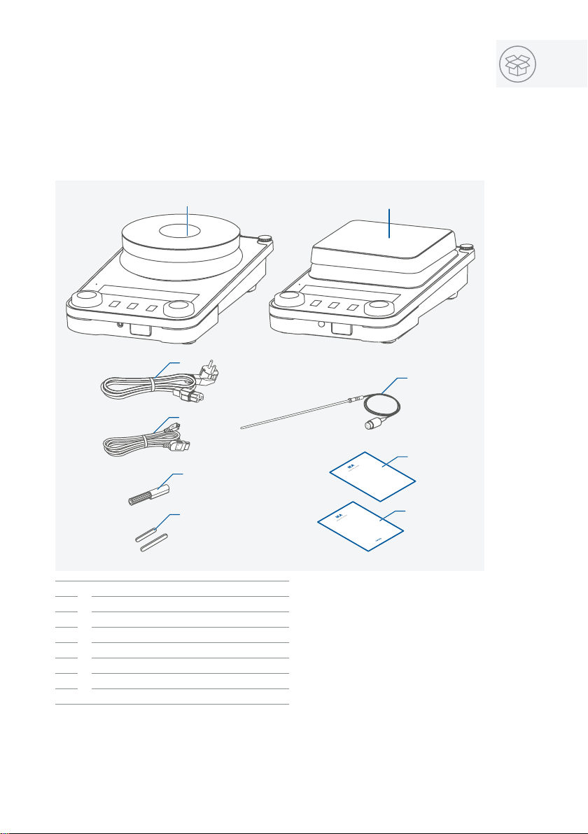
Unpacking
1 IKA Plate (RCT digital)
1
RCT 5 digital
/// Unpacking
Unpack the device carefully. Any damage should immediately be reported to the carrier (mail,
rail or freight forwarding company).
/// Scope of delivery
2
4
3
IKA Plate (RCT digital) / RCT 5 digital
1
Power cord
2
USB cord
3
Temperature sensor PT 1000.60
4
Screwdriver (safety circuit)
5
Magnetic stir bar IKAFLON 30 and 40 mm
6
User guide
7
Warranty card
8
7
5
6
Plate
IKA
8
11
Page 10
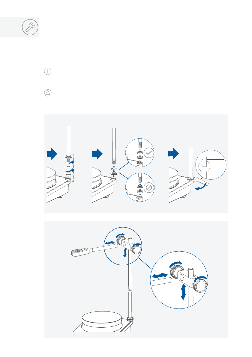
Installation
17 mm
/// Assembling support rod / extension etc.
› Review the mounting and safety instructions of the IKA boss head clamp prior to using it. (see
“Accessories”)
› The device must not be suspended from the support rod!
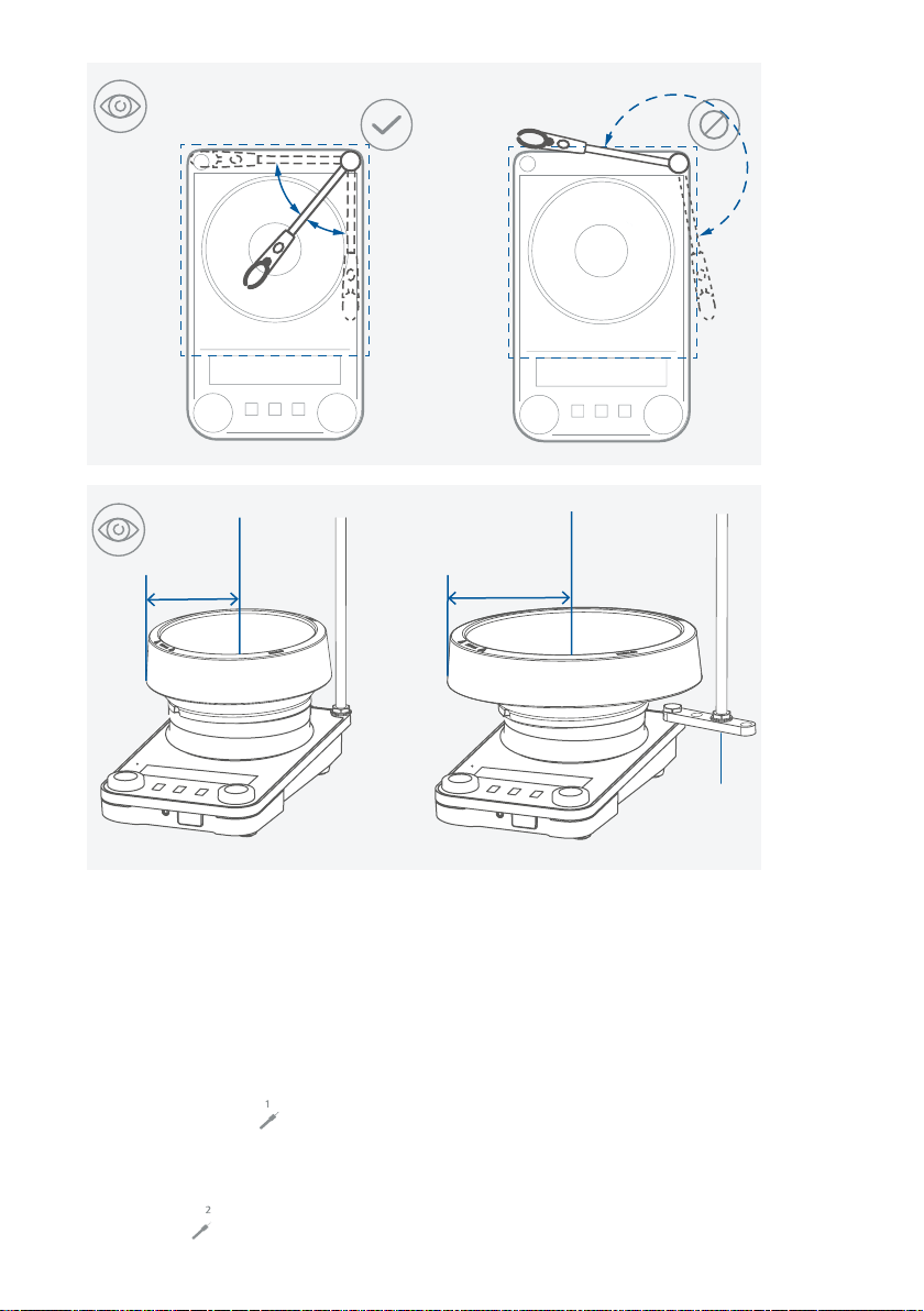
Risk of tipping!
› Make sure that the center of mass of the attached device does not protrude over the safe
area indicated below with a dotted rectangle.
!
Notice!
› When using bath attachments with a diameter over 180 mm, use support rod in conjunction
with an extension (see “Accessories”).
1
1.
2.
3.
2
4.
4.
3.
1.
1.
2.
2.3.
12
Page 11
≤ 90 mm
≥ 90 mm
H 16.3
/// Connecting an external temperature sensor / thermometer
1. Switch off the device [main switch (A)].
2. Connect safety contact thermometers according to DIN 12878 Class 2 or Temperature sensor
PT 1000 (single sensor) to the connection (M).
3. Switch on the device via the main switch (A).
Temperature sensor PT 1000:
› The actual temperature value shown on the display corresponds to the temperature of the
medium. The symbol shows on the display.
Contact thermometer ETS-D5 / ETS-D6:
› Follow the operating instructions for the contact thermometer.
The actual temperature value of the heating plate is shown on the display.
The symbol shows on the display.
13
Page 12

1
3.
2.
OFF
1.
2
14
≥ 20 mm
Page 13

Operator panel and display
/// Operator panel
I
H
C
N
O
E F
A Main switch (left « on, right « off)
B Adjustable safety circuit
Rotating / pressing knob - Temperature
C
setting
D Rotating / pressing knob - Speed setting
E “Menu“ button
F “Timer“ button
G “Lock“ button
H Display
G
B A
D
J K L M
I Standby LED
J Power socket
K USB Interface
L RS 232 Interface
Connection for PT 1000 temperature
M
sensor series, temperature probes or
contact plugs
N Heating plate
O Threaded hole for stand
15
Page 14

/// Display
07 09 11 10 15 17 16 08
14 | 13
SAFE
VISC
SET
01 Set speed value
02 Set temperature value
03 Motor running / rotation direction
04 Timer / counter
05 Temperature unit
06 Heating function activated
07 Actual temperature value
08 Actual speed value
09 Temperature control mode
SET
01
18030412050206
10 Operating mode
11 Safety circuit temperature
12 Viscosity trend value
13 |14PT 1000 temperature sensor connected
ETS-D5 / ETS-D6 connected
15 All parameters locked
16 USB connection with PC
17 Connection with PC established
18 Intermittent mode activated
16
Page 15

Operation
/// Start-up
1.
(°C / °F)
5.
ON
2.
OFF
3.
SAFE
SET
Temp 0...310 °C Speed 0...1500 rpm
(rpm)
4.
SET
17
Page 16

/// Stirring
›
Set the speed using the rotating / pressing knob (D).
The set speed value is shown on the right of the display.
›
Press the rotating / pressing knob (D) to start the stirring function.
1 2
SAFE
SET
Temp 0...310 °C Speed 0...1500 rpm
3 4
SET
Temp 0...310 °C Speed 0...1500 rpm
0...1500 rpm
SAFE
SET
(rpm)
SET
18
SAFE
SET
Temp 0...310 °C Speed 0...1500 rpm
SAFE
SET
SET
Temp 0...310 °C Speed 0...1500 rpm
SET
Page 17

/// Heating
Setting the safety temperature limit:
The maximum achievable heating plate temperature is restricted by an adjustable safety temperature limit. Once this limit has been reached, the device stops heating.
!
Notice!
The denominated temperatures should always refer to the center of the heating plate.
Warning!
The safety temperature limit must always be set at least 25 °C lower than the flash point of the
media to be processed!
The adjustable maximum heating plate temperature must always be set at least 15 °C under the
set safety temperature limit.
Setting range: see section “Technical data“.
After switching on the device, the safety temperature limit can be adjusted using a screwdriver.
Do not turn the setting screw beyond the clockwise or anticlockwise stop. This will cause irreparable damage to the potentiometer.
Functional test: safety circuit switch-off
› Heat the device to a temperature of over 100 °C.
› Set the safety temperature limit as far to the left as possible.
› The display will show: Er25
Safe temp. (°C / °F)
Safe temp.: 50...370 °C
SAFE
–
2.
+
1.
ON
SET
Temp 0...310 °C Speed 0...1500 rpm
Set temp.: 0...310 °C
Safe temp. ≥ Set temp. + 15 °C
Start heating:
› Set the safety temperature limit. (see “Setting the safety temperature limit”)
› Set the target temperature using the rotating / pressing knob (C).
The set temperature value is shown on the left of the display.
› Set the temperature control mode. (see “Temperature control mode”)
› Press the rotating / pressing knob (C) to start the heating function.
SET
19
Page 18

(°C / °F)
OFF
1
SAFE
SET
Temp 0...310 °C Speed 0...1500 rpm
3
SAFE
SET
Temp 0...310 °C Speed 0...1500 rpm
5
SAFE
SET
Temp 0...310 °C Speed 0...1500 rpm
2
0...310
°C
≤ Safe temp. − 15
SET
°C
PID / 2P / PI
SAFE
SET
Temp 0...310 °C Speed 0...1500 rpm
SET
4
SAFE
SET
SET
SET
Temp 0...310 °C Speed 0...1500 rpm
SET
20
General information for heating:
> 50 °C
Temp 0...310 °C Speed 0...1500 rpm
Page 19

› The set and actual temperature values are shown permanently on the display.
› When the heating function is switched on, the “Heating function activated” symbol is
displayed.
› When the device is switched off while the heating plate temperature is higher than 50 °C,
the display shows “Hot!” and the actual temperature value is shown, even if the device is
switched off.
/// Controlling the medium temperature limit using a contact
thermometer
The preferable method for controlling the average temperature is with contact thermometer.
After the set point temperature has been adjusted, this results in a short heating-up time, practically no temperature drift and only minor fluctuation in temperature.
A 6-pin jack is located on the rear side of the device for connecting the PT 1000 series, contact
thermometer or the contact plug. The electronics of the devices returns a test current that must
flow via connector pins 3 and 5 for the heating plate to heat up.
Safety contact thermometers:
Acc. to DIN 12 878 class 2 or acc. Gerstel are connected with a three-wire cable, the test current flows through the contact thermometer.
Safety function:
If the test current is interrupted because of e.g. breakage of contact thermometer or falling out
of the cable plug, the heating cuts off.
Contact thermometer without safety circuit:
Acc. to DIN 12 878 class 0. The device only heats if the test current circuit is closed by an electrical connection of the plug pins 3 and 5.
2-wire connecting cables:
Connect plug pins 3 and 5 of the device plug.
3-wire connecting cables:
Here the test current circuit can also be produced in the terminal head of the contact thermometer (connect plug pins 2 and 3).
A 3-wire cable with the required bridge is available (accessories).
Settings:
For detailed instructions for settings and limit values, please refer to the operating manual of
the device you are connecting.
The desired average temperature can be adjusted on the contact thermometer. The
required surface temperature of the heating plate can be selected with the rotating
/ pressing knob or button.
Adjusting the temperature of device to the maximum adjustable temperature will result in the
fastest possible heating time, but the average temperature may fluctuate to values above the
set-point temperature on the contact thermometer. By adjusting the rotating / pressing knob or
button to approximately twice the set-point value of contact thermometer (with a set-point of +
60 °C, the temperature of device would be set to + 120 °C), you will reach a good compromise
between a fast heating time and over-shooting the set point. If you adjust the temperature
of the device to exactly the set-point temperature, the medium will not reach the set-point
temperature because some loss of the heat will always occur between the heating plate and
the medium.
If a fault occurs in the control circuit, the maximum heating plate temperature can
be adjusted with the safety temperature setting screw.
21
Page 20

/// Menu structure
Operating mode
Factory settings
A
B
D
-
-
Temperature control mode
Intermittent mode /
Rotation direction
Beep
Temperature unit
Error 5
Timer expired
Safe / Visc
SAFE
PID
2P
PI
Intermittent mode
Rotation direction
Automatic reverse rotation
ON
OFF
°C
°F
Stop heating
Stop stirring
Safe
Visc
yes
no
yes
no
Run time
Pause time
ON
OFF
-
-
00:00 [mm:ss]
00:03 [mm:ss]
Clockwise (continuous)
-
-
-
05:00 [mm:ss]
-
-
-
22
Factory reset
Probe calibration
Software version
yes
no
(default) set
(not default) reset
no
yes
2 Point
no
yes
-
-
-
-
Page 21

/// Menu details
t
PID
t
Operating mode:
Mode A:
All settings will be stored if the device is switched off or disconnected from the power supply.
The stirring and heating functions will be set to OFF when the device is powered on. The safety
circuit can be set or modified. When the power supply switch is switched on, A is displayed.
Mode B:
All settings will be stored if the device is switched off or disconnected from the power supply.
The stirring and heating functions will be set to ON or OFF when the device is powered on,
depending on the previous status of the device. The safety circuit can be set or modified. When
the power supply switch is switched on, B is displayed.
Mode D:
When switching the device on, the safe temperature has to be confirmed by pushing one of
the rotating / pressing knobs.
During operation, in mode D the device behaves the same as in Mode A with the exception
that:
› The temperature / speed setting must be confirmed by pressing the rotating / pressing knob.
To change the temperature / speed setting, turn the rotating / pressing knob until the desired
value appears.
› The new value flashes for 5 seconds on the display. Confirm the new temperature / speed
setting by pressing the rotating / pressing knob, otherwise the temperature / speed setting
value will skip back to its previous value.
Temperature control mode:
When using an external PT 1000 temperature sensor, you can choose below control modes:
PID mode:
Good control results, minimized overshooting, slow rise in temperature.
2P-mode (two-point controller):
Maximum heating rate, increased overshooting.
PI mode:
Good control results, for some of the heating blocks.
2P
T
Set
T
Set
Temp. control
23
Page 22

Intermittent mode / Rotation direction:
Intermittent mode:
In intermitted mode, the stirring function is interrupted cyclically. The run time (0 / 10 sec – 10
min, 10 sec steps) and pause time (3 sec – 5 min, 1 sec steps) should both be set. When the
intermittent mode is activated, a decimal point appears on the display (
).
Rotation direction:
You can select the continuous rotation by setting the time to 00:00:00 via pushing the rotating
/ pressing knob (D). Afterwards the rotation direction can be selected by turning the rotating /
pressing knob (D).
Alternatively to continuous stirring, you can set the direction of rotation reversal. Then the
rotation direction changes after each pause.
In this way the magnetic rod is captured and any liquid still rotating is gradually slowed down.
Then the drive accelerates to the target speed.
Beep:
The menu item “Beep“ allows the user to turn on / off the sound that occurs when the timer
reaches 00:00:00 or an error message appears.
Temperature unit:
The menu item “Temperature unit“ allows the user to select the desired unit between ”°C” or
”°F” for displaying the temperature.
Error 5:
Providing safety protection, Error 5 is taken to recognize that the sensor has not been placed in
the medium when the heating is switched on.
!
Notice!
You can set a value from 0.5 to 30 min for this time limit depending on the application. If time limit
is set to 0 min, the “Er05” detection is disabled.
24
Caution!
This function will only be active if:
› sensor temperature is < 50 °C
› difference between target temperature and sensor temperature > 5 K.
Timer expired:
You can specify the procedure of heating and stirring function if the timer achieves 00:00:00.
Next to the visually / audible information you can decide independently if the heating and stirring should be stopped automatically if the timer is expired or should continue.
Caution!
Switching off the stirring function can lead to a delayed boiling.
Page 23

Safe / Visc:
Once the “VISC / SAFE“ has been set to “VISC“, the viscosity trend value will be shown on the
display. The torque trend measurement is used to deduce the change in viscosity of the reaction
medium. The devices are not designed to measure absolute viscosity. They only measure and
display the relative change in the viscosity of the medium from a starting point specified by the
user.
Once the speed of the motor and magnetic rod in the medium have stabilized to the target
speed, the viscosity measurement is started at 100 %. The change in the viscosity is then shown
in %.
The value can always be reset to 100 % by pushing the „Menu“ button for 2 seconds.
!
Notice!
Torque trend measurement only works for a constant set speed for the duration of the measurement. As a result, intermittent mode cannot be used in conjunction with torque trend measurement.
The current control variable is saved as the reference 100 % P and shown on the digital display. The change in the viscosity is then shown in %.
When on the “VISC“ screen, the screen will switch to “SAFE“ if the adjustment of the safety
temperature is activated, during which you may set the safety temperature and the screen will
switch back to “VISC“ once the setting is done, otherwise it will switch back to “VISC“.
Factory reset:
The menu item ”Factory reset” allows the user to reset all the system settings to the original
standard values set at dispatch from the factory (see “Menu structure”).
Probe calibration:
In order to use tolerances to limit temperature deviations, the user can calibrate the temperature sensor in conjunction with the device.
2-point calibration:
Calibration using two temperatures.
!
Notice!
For calibration, select a suitable stirring speed for the application.
Use a calibrated temperature reference meter for control.
25
Page 24

Probe cal.
“EXT” temp.
SAFE
SET
1st temp.
SET
1st speed
2.
SAFE
SET
SAFE
2nd temp.
1.
SET
= 2nd temp.
“EXT“ temp.
SET
1.
SAFE
SET
SAFE
= 1st temp.
SAFE
SET
Software version:
Turn the rotating / pressing knob (D) to change the menu item to ”Software version”.
/// Timer / Counter
SET
SET
SET
26
› Press the “Timer” button for 2 seconds to activate the timer / counter function.
Page 25

2.
1.
27
Page 26

Timer mode (count down):
› Set the desired value with the rotating / pressing knob (D). By pressing the knob the value is
confirmed.
› Pressing the button (F) to start the timer.
› To pause the timer, press the button (F).
› To restart the timer, press the button (F) again.
› After the timer has elapsed, the display starts flashing and a beep sounds (depending on the
menu setting).
Counter mode (count up):
› To select the counter mode, you must set all the values to 00:00:00.
› The value is confirmed by pressing the rotating / pressing knob (D).
› Pressing the button (F) to start the counter.
› Press the button (F) to pause the counter.
› To restart the counter, press the button (F) again.
› If the elapsed time exceeds the value of 100 hours, the display switches from hour:minute:sec-
ond mode to day:hour mode.
› If the elapsed time exceeds the value of 100 days, the counter will reset to 00:00:00.
!
Notice!
› From each state of the timer / counter, press the button (F) for 2 seconds to exit the timer /
counter.
/// Lock button
› An active locking is indicated by the symbol ( ).
› Even after a power failure, the device retains the lock status.
28
SAFE
SET
Temp 0...310 °C Speed 0...1500 rpm
SET
Page 27

Interfaces and outputs
The device can be operated by computer via an RS 232 or USB interface using the laboratory
software labworldsoft®.
The device software can also be updated with a PC via the RS 232 or USB port.
!
Notice!
Please comply with the system requirements together with the operating instructions and help
section included with the software.
/// USB interface:
The connected devices and their properties are detected automatically. The USB interface is
used in conjunction with software control for “remote” operation and can also be used for
software update of the device.
/// USB device drivers:
First, download the latest driver for IKA devices with USB interface from:
http://www.ika.com/ika/lws/download/usb-driver.zip
Install the driver by running the setup file. Then connect the IKA device to the PC via the USB
data cable and follow the instructions.
The data communication is via a virtual COM port.
/// RS 232 interface:
Configuration:
› The functions of the interface connections between the device and the automation system
are chosen from the signals specified in EIA standard RS 232 in accordance with DIN 66 020
Part 1.
› For the electrical characteristics of the interface and the allocation of signal status, standard
RS 232 applies in accordance with DIN 66 259 Part 1.
› Transmission procedure: asynchronous character transmission in start-stop mode.
› Type of transmission: full duplex.
› Character format: character representation in accordance with data format in DIN 66 022 for
start-stop mode. 1 start bit; 7 character bits; 1 parity bit (even); 1 stop bit.
› Transmission speed: 9600 bit/s.
› Data flow control: none.
› Access procedure: data transfer from the device to the computer takes place only at the
computer’s request.
/// Command syntax and format:
The following applies to the command set:
› Commands are generally sent from the computer (Master) to the device (Slave).
› The device sends only at the computer’s request. Even fault indications cannot be sent spon-
taneously from the device to the computer (automation system).
› Commands are transmitted in capital letters.
› Commands and parameters including successive parameters are separated by at least one
space (Code: hex 0x20).
› Each individual command (incl. parameters and data) and each response are terminated with
Blank CR LF (Code: hex 0x20 hex 0x0d hex 0x20 hex 0x0A) and have a maximum length of
80 characters.
› The decimal separator in a number is a dot (Code: hex 0x2E).
29
Page 28

The above details correspond as far as possible to the recommendations of the NAMUR working party (NAMUR recommendations for the design of electrical plug connections for analogue
and digital signal transmission on individual items of laboratory control equipment, rev. 1.1).
The NAMUR commands and the additional specific IKA commands commissioning serve only
as low level commands for communication between the device and the PC. With a suitable terminal or communications program these commands can be transmitted directly to the device.
The IKA software package, Labworldsoft
®
, provides a convenient tool for controlling device
and collecting data under MS Windows, and includes graphical entry features, for motor speed
ramps for example.
NAMUR Commands Function
IN_NAME
IN_PV_1
IN_PV_2
IN_PV_4
IN_PV_5
IN_SP_1
IN_SP_3 Read rate set safety temperature value
IN_SP_4 Read rate speed value
OUT_SP_1_x
(x=0...310)
OUT_SP_4_x
(x=0...1500)
START_1 Start the heater
STOP_1 Stop the heater
START_4 Start the motor
STOP_4 Stop the motor
RESET Switch to normal operating mode
SET_MODE_n
(n=A, B, or D)
OUT_SP_12@n Setting WD safety limit temperature with set value echo
OUT_SP_42@n Setting WD safety limit speed with set value echo
OUT_WD1@m Watchdog mode 1: if event WD1 should occur, the heating and stirring
OUT_WD2@m Watchdog mode 2: if event WD2 should occur, the speed target value is
Read the device name
Read actual external sensor value
Read actual hotplate sensor value
Read stirring speed value
Read viscosity trend value
Read rated temperature value
Adj ust the set temperature value
Adjust the set speed value
Set operating mode
functions are switched off and Er02 is displayed. Set watchdog time to m
(20- 1,500) seconds, with watchdog time echo. This command launches the
watchdog function and must be transmitted within the set watchdog time.
changed to the WD safety speed limit and the temperature target value is
changed to the WD safety temperature limit value. The warning WD is displayed. The WD2 event can be reset with OUT_WD2@0 - this also stops
the watchdog function. Set watchdog time to m (20- 1,500) seconds, with
watchdog time echo. This command launches the watchdog function and
must be transmitted within the set watchdog time.
30
Page 29

”Watchdog” functions, monitoring of the serial data flow:
GND 5
5 GND
6
7
8
9
5
4
3
2
1
USB B
USB A
If, once this function has been activated (see NAMUR commands), there is no retransmission of
the command from the computer within the set time (“watchdog time”), the heating and stirring
functions are switched off in accordance with the set “watchdog” function or are changed to the
set target values.
The data transmission may be interrupted by, for example, a crash in the operating system, a power
failure in the PC or an issue with the connection table between the computer and the device.
“Watchdog” – mode 1:
If there is an interruption in data communications (longer than the set watchdog time), the heating
and stirring functions are switched off and Er02 is displayed.
“Watchdog” – mode 2:
If there is an interruption in data communications (longer than the set watchdog time), the speed
target value is changed to the WD safety speed limit and the temperature target value is changed
to the WD safety temperature limit value. The warning WD is displayed.
PC 1.1 cable:
This cable is required to connect RS 232 port to a PC.
1
2
3
4
5
1
TxD 2
RxD 3
4
1
2 RxD
3 TxD
4
9
8
7
6
PC
USB cable A – B:
This cable is required to connect USB port to a PC.
31
Page 30

Maintenance and cleaning
› The device is maintenance-free. It is only subject to the natural wear and tear of components
and their statistical failure rate.
/// Cleaning:
› For cleaning disconnect the mains plug!
› Use only cleaning agents which have been approved by IKA to clean IKA devices.
These are water (with tenside) and isopropanol.
› Wear protective gloves during cleaning the devices.
› Electrical devices may not be placed in the cleansing agent for the purpose of cleaning.
› Do not allow moisture to get into the device when cleaning.
› Before using another than the recommended method for cleaning or decontamination, the
user must ascertain with IKA that this method does not destroy the device.
/// Spare parts order:
› When ordering spare parts, please give:
- device type.
- serial number, see type plate.
- software version (upon device starting up).
/// Repair:
Please only send devices in for repair that have been cleaned and are free of materials which
might present health hazards.
If your appliance requires repair, return it in its original packaging. Storage packaging is not
sufficient when sending the device - also use appropriate transport packaging.
32
Page 31

Error codes
› The fault is shown by an error code on the display as following if the error occurs.
Proceed as follows in such cases:
- Turn off the device by using the main switch (left « on, right « off).
- Carry out corrective measures.
- Restart the device.
Error code | Causes | Effect | Solutions
Er02 - Watchdog error
Causes
Effect
Solutions
Er03 - Temperature inside device is higher than 80 °C
Causes
Effect
Solutions
Er04 - Motor control is unavailable
Causes
Effect
Solutions
›
PC does not transmit any data within the set watchdog time
›
connection to PC interrupted
›
heating switched off
›
motor switched off
›
change watchdog time
› transmit data from PC within set watchdog time (OUT_WDx@m)
check cable and plug
›
›
heat accumulation between heating plate and housing
› permitted ambient temperature exceeded
›
heating switched off
› switch device off, leave to cool and switch on again
› change experiment
observe maximum permissible ambient temperature
›
›
motor blocked or overloaded
›
heating switched off
› motor switched off
› reduce load torque or use smaller magnetic rods
› reduce target speed
Er05 - No temperature increase measured by temperature sensor
(selected time in menu)
Causes
Effect
Solutions
› sensor not in medium
› volume of medium to be measured too large
› heat conductivity of medium to be measured too low
› heat conductivity of the vessel is too low
› in the case of indirect heating, the overall heat
large
›
heating switched off
› place the sensor in the medium
› reduce the volume of the media
› use a carrier fluid with better heat conductivity properties
› replace the glass vessel with a metal pot
› increase the “Time-out” period
conductivity resistance is too
33
Page 32

Er06 - Interruption of the safety circuit
Causes
Effect
Solutions
› break in safety circuit
›
heating switched off
› plug in contact plug
› plug in PT 1000 temperature sensor
› replace faulty connecting cable, plug, or contact thermometer
Er13 - Hotplate safety sensor, open-circuit
Causes
Effect
Solutions
› target / current different of the adjustable safety circuit for minimum temperature
monitoring
›
heating switched off
› after switching on, change the SAFE TEMP to a different value; if this solves the
issue, the previous value can be reset by switching the device off and on again
Er14 - External temperature sensor, short-circuit
Causes
Effect
Solutions
› short circuit in temperature sensor plug
› short circuit in the cable or temperature sensor
›
heating switched off
› check the plug
› replace the temperature sensor
Er21 - Fault during heating plate safety test
Causes
Effect
Solutions
› safety relay does not open
›
heating switched off
› switch device off, leave to cool and switch on again
34
Er22 - Fault during heating plate safety test
Causes
Effect
Solutions
› S_CHECK cannot generate H_S_TEMP
›
heating switched off
› switch device off, leave to cool and switch on again
Er24 - Heating plate temperature is higher than the set safety temperature
Causes
Effect
Solutions
› s
afety temperature
heating plate
› disconnection of heating plate control temperature sensor
›
heating switched off
› leave the heating plate to cool
› set the safety temperature higher
has been set to lower than the current temperature of the
Er25 - Heating switching element monitoring fail
Causes
Effect
Solutions
› heater control circuit switch (TRIAC) short-circuited
› safety relay has interrupted the heating circuit
› heater or the supply line is disconnected
› disconnection of heating plate safety temperature sensor
›
heating switched off
› switch device off, leave to cool and switch on again
Page 33

Er26 – Plate temperature > plate safety temperature (more than 40 K)
Causes
Effect
Solutions
› irregular temperature distribution across heating plate due to sporadic heat
dissipation
› defective control or safety temperature sensor
›
heating switched off
› switch device off, leave to cool and switch on again
› ensure regular heat dissipation when using metal blocks, etc. on the flat surface of
the heating plate
Er31 – Fault in the heater switch element
Effect
Solutions
›
heating switched off
› contact customer service
Er44 – Heating plate safety temperature is higher than the set safety temperature
Causes
Effect
Solutions
› SAFE TEMP H (Hotplate) has been set to lower than the safety temperature of the
heating plate
› disconnection of heating plate safety temperature sensor
›
heating switched off
› leave the heating plate to cool
› set the SAFE TEMP H (Hotplate) higher
Er46 – Plate safety temperature > plate temperature (more than 40 K)
Causes
Effect
Solutions
› irregular temperature distribution across heating plate due to sporadic heat dissi-
pation
› defective control or safety temperature sensor
›
heating switched off
› switch device off, leave to cool and switch on again
› ensure regular heat dissipation when using metal blocks, etc. on the flat surface of
the heating plate
›
If the actions described fails to resolve the fault or another error code is displayed then take one
of the following steps:
-
contact the service department.
-
send the device for repair, including a short description of the fault.
35
Page 34

Technical data
IKA Plate (RCT digital) RCT 5 digital
General data
Voltage 220 – 230 VAC ± 10 %
Frequency 50 / 60 Hz
Power input 650 W 900 W
Power input standby 1.6 W
Self-heating of the heating plate by max. stirring
(RT:22° C/duration:1h)
Automatic reverse rotation yes
Intermittent mode yes
Viscosity trend measurement yes
Timer yes
Interface USB, RS 232
Permissible ambient temperature + 5 ... + 40 °C
Permissible relative humidity 80 %
Protection class according to DIN EN 60529 IP 42
Protection class I
Contamination level 2
Overvoltage category II
Plate material Aluminium alloy Aluminium with
Plate dimensions Ø 135 mm 137 x 137 mm
Dimensions (W × D × H) 160 × 270 × 85 mm
Weight 2.3 kg 2.6 kg
Operation at a terrestrial altitude max. 2000 m
Stirring function
Number of stirring positions 1
Max. stirring quantity (H
Speed range 0 / 50 ... 1500 rpm
Speed display set-value LCD
Speed display actual-value LCD
Speed setting rotating / pressing knob
Speed setting accuracy 10 rpm
Speed variation (no load, nominal voltage,
at 1500 rpm, ambient temperature + 25 °C)
Stirring bar length 30 ... 80 mm
O) 20 l
2
115 VAC ± 10 %
100 VAC ± 10 %
+ 13 °C
ceramic coating
± 2 % of 1500 rpm
36
Page 35

Heating function
Heat output 600 W 850 W
Heating temperature range RT + device self-heating ... 310 °C
Temperature setting range 0 ... 310 °C
Temperature display set-value LCD
Temperature display actual-value LCD
Temperature setting rotating / pressing knob
Temperature setting resolution of heating plate 1 K
Temperature setting resolution of medium 1 K
Heating rate (1 l water in H 1500) 6.5 K / min 7.5 K / min
Temperature control accuracy of heating plate (at 100 °C) ± 5 K
Adjustable safety circuit 50 °C ... 370 °C
External temperature sensor / thermometer
Connection for external temperature sensor / thermometer PT 1000 series, ETS-D5, ETS-D6
Temperature control accuracy
(500 ml water in 600 ml glass beaker,
40 mm bar, 600 rpm, 50 °C)
Temperature sensor PT 1000 deviation
EN 60751 class A ≤ ± (0.15 + 0.002 × ITI)
Sensor in medium detection (Error 5) yes
± 0.5 K ( with temperature sensor PT 1000)
± 0.5 K (with thermometer ETS-D5)
± 0.2 K (with thermometer ETS-D6)
› Subject to technical changes!
37
Page 36

Warranty
›
In accordance with IKA warranty conditions, the warranty period is 24 months. For claims
under the warranty please contact your local dealer. You may also send the device direct to
our factory, enclosing the delivery invoice and giving reasons for the claim. You will be liable
for freight costs.
›
The warranty does not cover worn out parts, nor does it apply to faults resulting from
improper use, insufficient care or maintenance not carried out in accordance with the
instructions in this operating manual.
38
 Loading...