

Page 1
20000006451
MIDI_MAXI_032016
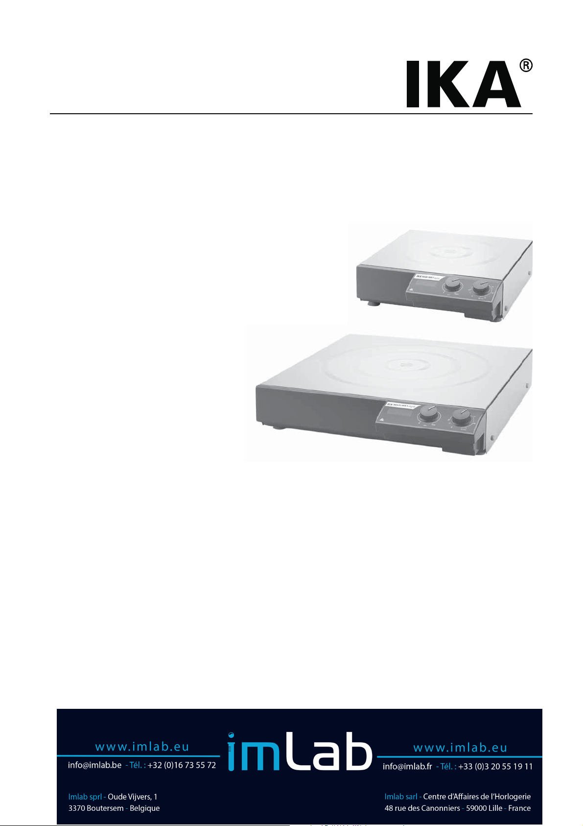
IKA® MIDI MR 1 digital
®
IKA
MAXI MR 1 digital
Page 2
Source language: German
EN
Contents
Page
Declaration of conformity 11
Explication of warning symbols 11
Safety instructions 11
Correct use 13
Unpacking 13
Commissioning 13
Interface and output 14
Maintenance and cleaning 16
Error codes 16
Accessories 16
Technical data 17
Warranty 17
Declaration of conformity
We declare under our sole responsibility that this product is in compliance with the regulations 2014/35/EU, 2014/30/EU
and 2011/65/EU and conforms to the standards or normative documents: EN 61010-1, EN 61010-2-051, EN 61326-1,
EN 60529 and EN ISO 12100.
Explication of warning symbols
DANGER
WARNING
CAUTION
NOTICE
NOTICE
Indicates an (extreme) hazardous situation, which, if not avoided, will result in death, serious
injury.
Indicates a hazardous situation, which, if not avoided, can result in death, serious injury.
Indicates a potentially hazardous situation, which, if not avoided, can result in injury.
Indicates practices which, if not avoided, can result in equipment damage.
Note the hazards of magnetism!
Safety instructions
General information:
• Read the operating instructions completely before
starting up and follow the safety instructions.
• Keep the operating instructions in a place where they can
be accessed by everyone.
• Ensure that only trained staff work with the device.
• Follow the safety instructions, guidelines, occupational
health and safety and accident prevention regulations.
• Socket must be earthed (protective ground contact).
• The socket for the mains cord must be easily accessible.
• The feet of the device must be clean and undamaged.
• Check the device and accessories for damage before each
use them. Do not use damaged components.
• Do not operate the device in explosive atmospheres, with
hazardous substances or under water.
• The device may heat up when in use.
11
Page 3
• Do not move or transport the device when it is operating
or connected to the power supply.
• Safe operation is only guaranteed with the accessories described in the ”Accessories” chapter.
• Always disconnect the plug before attaching accessories.
• The device can only be disconnected from the mains supply by pulling out the mains plug or the connector plug.
• The device can only be opened by technical experts, even
during repair. The device must be unplugged from the
power supply before opening. Live parts inside the device
may still be live for some time after unplugging from the
power supply.
DANGER
if you have any questions.
Process pathogenic materials only
in closed vessels under a suitable
fume hood. Please contact IKA
Beware of hazards due to:
WARNING
- flammable materials
- incorrect container size
- overfilling of media
- unsafe condition of container.
®
NOTICE
• The working plate can heat up due to the action of the
drive magnets at high motor speeds.
• The centre of gravity of the assembly must lie within the
surface on which it is set up.
• It may be possible for wear debris from rotating accessory
parts to reach the material being processed.
• When using PTFE-coated magnetic bars, the following
has to be noted: Chemical reactions of PTFE occur in contact with molten or solute alkali metals and alkaline earth
metals, as well as with fine powders of metals in groups 2
and 3 of the periodic system at temperatures above 300
°C - 400 °C. Only elementary fluorine, chlorotrifluoride
and alkali metals attack it; halogenated hydrocarbons
have a reversible swelling effect.
(Source: Römpps Chemie-Lexikon and ”Ulmann”, Volume 19)
For protection of the user:
WARNING
to be processed. There may be a risk from:
- splashing and evaporation of liquids
- ejection of parts
- release of toxic or combustible gases.
Effects of the magnetic field
have to be taken into account
(e.g. data storage media, cardiac
pacemakers ...).
Wear your personal protective
equipment in accordance with
the hazard category of the media
For protection of the device and accessories:
• Set up the device in a spacious area on an even, stable,
clean, non-slip, dry and fireproof surface.
• The voltage stated on the type plate must correspond to
the mains voltage.
• Removable parts must be refitted to the device to prevent
the infiltration of foreign objects, liquids etc..
• Protect the device and accessories from bump and impact.
• Do not cover the device, even partially e.g. with metallic
plates or film. This may result in overheating.
Performing trials:
Reduce the speed if:
NOTICE
- the medium splashes out of the vessel
- the device is not running smoothly
- dynamic forces start to cause the device and/or the ves-
sels placed on it to move around.
• Make certain that the device is set at the lowest speed
(left hand position) before commissioning; otherwise, the
device will start to run at the speed set in last operation.
Gradually increase the speed.
• After an interruption in the power supply or a mechanical interruption during working process, the device will
restart automatically.
DANGER
cessing. This also applies to any extra energy produced in
other ways, e.g. through light irradiation.
Only process media that will not
react dangerously to the extra
energy produced through pro-
12
Page 4

Correct use
®
The IKA
MIDI MR 1 digital and MAXI MR 1 digital is
a magnetic stirrer without heating function. The devices are
suitable for stirring and mixing liquid substances up to 50
liter (MIDI MR1 digital) and 150 liters (MAXI MR1 digi-
tal). The built-in stirring drive permits the stirring of substances with the aid of a magnetic stirring bar in the vessel.
The mixing intensity is dependent on the motor speed and
the size of the magnetic bar.
• Use:
- for stirring and mixing liquids.
Intend use: Tabletop device
• Range of use (indoor use only):
- Laboratories - Schools
- Pharmacies - Universities
Unpacking
• Unpacking:
- Please unpack the device carefully.
- In the case of any damage a detailed report must be
sent immediately (post, rail or forwarder).
This device is suitable for use in all areas except:
- Residential areas.
- Areas that are connected directly to a low-voltage supply
network that also supplies residential areas.
The safety of the user cannot be guaranteed:
- If the device is operated with accessories that are not supplied or recommended by IKA
®
.
- If the device is operated improperly or in contrary to the
®
IKA
specifications.
- If the device or the printed circuit board are modified by
third parties.
• Delivery scope:
®
- IKA
MIDI MR 1 digital or MAXI MR 1 digital ac-
cording to order
- Magnetic stirring bar
- Mains cable
- USB 2.0 cable A – B
- Operating instructions
- Warranty Card.
Commissioning
Check whether the voltage specified on the type plate
matches the mains voltage available.
The power socket used must be
earthed (protective earthing).
If above conditions are met, the device is ready for operation after plugging in the mains plug.
If these conditions are not met, safe operation is not guaranteed and the device could be damaged.
Observe the ambient conditions (temperature, humidity,
etc.) listed under “Technical Data”.
The device can be operated in two modes, “Continuous
mode“ or “Timer mode“:
Fig. 3
BC
Continuous mode:
) To switch the device on, turn the “On/Off” and “Timer”
rotary knob (B, see Fig. 3) clockwise to the “1” position.
Ö The device is now running in “Continuous mode”.
) To switch the device off, turn the “On/Off” and “Timer”
rotary knob (B) to “0” position.
Timer mode:
) To switch the device on, turn the “On/Off” and “Timer”
rotary knob (B) clockwise after the “
“ position.
Ö The running time can be adjusted to any value between
0 and 55 minutes.
Ö After the selected time period has elapsed, the switch
will automatically return to the “0”position and the de-
vice will remain switched off.
Ö The time period selected can be adjusted at any time.
Setting the motor speed:
) Set the motor speed by turning the “Speed” rotary knob
(C, see Fig. 3). The motor speed can be set to between
0 to 1000 rpm for MIDI MR 1 digital and 0 to 600 for
MAXI MR1 digital.
13
Page 5

Interface and output
The device can be connected to a PC and operated with
the laboratory software labworldsoft
®
through the RS 232
interface (G, see Fig. 2) or USB interface (H, see Fig. 2).
Note: Please observe the system requirements as well as
the operating instruction and help section of the software.
USB interface:
The Universal Serial Bus (USB) is a serial bus for connecting the
device to the PC. Equipped with USB devices can be connected
to a PC during operation (hot plugging). Connected devices
and their properties are automatically recognized.
®
Use the USB interface in conjunction with labworldsoft
for
operation in “Remote” mode and also to update the firmware.
USB device drivers:
First, download the latest driver for IKA
®
devices with USB
interface from:
http://www.ika.com/ika/lws/download/usb-driver.zip.
Install the driver by running the setup file. Then connect the
®
IKA
device through the USB data cable to the PC.
The data communication is via a virtual COM port. Configuration, command syntax and commands of the virtual COM
ports are as described in RS 232 interface.
RS 232 interface:
Configuration:
- The functions of the interface connections between the
device and the automation system are chosen from the
signals specified in EIA standard RS 232 in accordance with
DIN 66 020 Part 1.
- For the electrical characteristics of the interface and the
allocation of signal status, standard RS 232 applies in accordance with DIN 66 259 Part 1.
- Transmission procedure: asynchronous character transmis-
sion in start-stop mode.
- Type of transmission: full duplex.
- Character format: character representation in accordance
with data format in DIN 66 022 for start-stop mode. 1
start bit; 7 character bits; 1 parity bit (even); 1 stop bit.
- Transmission speed: 9600 bit/s.
- Data flow control: none.
- Access procedure: data transfer from the device to the
computer takes place only at the computer’s request.
Command syntax and format:
The following applies to the command set:
- Commands are generally sent from the computer (Master)
to the device (Slave).
- The device sends only at the computer’s request. Even
fault indications cannot be sent spontaneously from the
device to the computer (automation system).
- Commands are transmitted in capital letters.
- Commands and parameters including successive parameters are separated by at least one space (Code: hex 0x20).
- Each individual command (incl. parameters and data) and
each response are terminated with Blank CR LF (Code: hex
0x20 hex 0x0d hex 0x20 hex 0x0A) and have a maximum
length of 80 characters.
- The decimal separator in a number is a dot (Code: hex
0x2E).
The above details correspond as far as possible to the recommendations of the NAMUR working party (NAMUR recommendations for the design of electrical plug connections
for analogue and digital signal transmission on individual
items of laboratory control equipment, rev. 1.1).
The NAMUR commands and the additional specific IKA
®
commands serve only as low level commands for communication between the device and the PC. With a suitable
terminal or communications programme these commands
can be transmitted directly to the device. The IKA
ware package, Labworldsoft
®
, provides a convenient tool
®
soft-
for controlling the device and collecting data under MS
Windows, and includes graphical entry features, for motor
speed ramps for example.
Commands:
Commands Function
IN_NAME Input description name.
IN_SP_4 Reading the set rated value of rpm.
IN_PV_4 Reading the real value of rpm.
OUT_SP_4 n Setting the rated value of rpm to n.
OUT_SP_42@n Setting the WD safety speed with the echo of the set value
OUT_WD1@m
Watchdog mode 1: When a WD1 event occurs, the stirring functions are shut down and message PC
1 is displayed. Set the watchdog time to m (20...1500) seconds, with echo of the watchdog time. This
instruction starts the watchdog function and must be sent within the set watchdog time.
14
Page 6

OUT_WD2@m Watchdog mode 2: When a WD2 event occurs, the speed set point will be set to the WD safety
set point speed. The PC 2 warning is displayed. The WD2 event can be reset with OUT_WD2@0resetting also blocks the watchdog function. Set the watchdog time to m (20...1500) seconds, with
echo of the watchdog time. This command starts the watchdog function and must be sent within
the set watchdog time.
RESET
Switching off the device function.
START_4 Starting the device (remote) function
STATUS_4
Display of status:
10: Manual operation without fault
11: Automatic operation Start (without fault)
12: Automatic operation
Stop (without fault)
< 0: error code:
- 1: error 1
- ... (see „Error codes“ table)
Note: when disconnecting the RS 232 or USB cable while the device is running, the device stays in PC mode. To reset to
function without PC, switch the device off and on again.
PC 1.1 Cable:
This cable is required to connect RS 232 interface (G) to a PC.
6
7
8
9
Fig. 4
1
2
3
4
5
RxD 2
TxD 3
GND 5
RTS 7
CTS 8
1
4
6
9
USB 2.0 cable A - B:
This cable is required to connect USB interface (H) to a PC.
4
1
32
USB B
Fig. 5
1
2 RxD
3 TxD
4
5 GND
6
7 RTS
8 CTS
9
9
8
7
6
PC
USB A
5
4
3
2
1
1
2
3
4
15
Page 7

Maintenance and cleaning
The device is maintenance-free. It is only subject to the natural
wear and tear of components and their statistical failure rate.
Cleaning:
Disconnect main plug prior to cleaning!
Use only cleaning agents which have been approved by
®
IKA
to clean IKA® devices.
Dirt Cleaning agent
Dye Isopropyl alcohol
Construction
Water containing tenside/isopropyl alcohol
material
Cosmetics
Water containing tenside/isopropyl alcohol
Foodstuff Water containing tenside
Fuel Water containing tenside
For materials which are not listed, please request information from IKA
®
application support.
Wear protective gloves while cleaning the device.
Electrical devices may not be placed in the cleansing agent for
the purpose of cleaning.
Do not allow moisture to get into the device when cleaning.
If a different cleaning or decontamination method than the
method defined by IKA
with IKA
®
that this method does not damage the device.
®
is planned, the user must ascertain
Spare parts order:
When ordering spare parts, please give:
- Machine type.
- Serial number, see type plate.
-
Item and designation of the spare part,
see www.ika.com, spare parts diagram and list
.
Repair:
Please send the device for repair only after it has
been cleaned and is free from any materials which
may constitute a health hazard.
For repair, please request the “Decontamination Certificate” from IKA
®
, or download printout of it from the IKA®
website www.ika.com.
Return the device in its original packaging. Storage packaging is not sucient. Also, please use suitable shipping package materials.
Error codes
Any malfunctions during operation will be identified by an error message on the display.
Proceed as follows in such cases:
) Switch off device using the main switch at the back of the device.
)Carry out corrective measures.
)Restart device.
Error code Effect Cause Solution
Err 10
Err 14 Stop stirring or change according to
Stirring function doesn‘t start.
Speed setting signal error.
- Contact IKA® service department.
PC communication failure - Check communication cable.
relating setting.
If the actions described fails to resolve the fault or another error code is displayed then take one of the following steps:
- Contact the service department
- Send the device for repair, including a short description of the fault.
Accessories
®
• IKAFLON
• TRIKA
Magnetic stirring bar
®
Magnetic stirring bar
• RSE Stirring bar remover
See more accessories on www.ika.com.
• PC 1.1 Cable
• Labworldsoft
®
16
Page 8

Technical data
MIDI MR 1 digital MAXI MR 1 digital
Operating voltage VAC 230 ± 10 %
115 ± 10 %
100 ± 10 %
Frequency Hz 50 / 60
Power input W 70 80
Power output W 19 35
Max. load on top surface kg 75 200
Stirred quantity max. (H
Maximum magnetic bar (L x Ø) mm 80 x 10 155 x 27
Infinitely adjustable speed range rpm 0 ... 1000 0 ... 600
Speed tolerance < ± 10 % of maximum speed
Speed display LED
Operating mode continuous operation and timer
Timer min ∞ / 1 ... 55
Interface USB, RS 232
Fuse
Permissible ambient temperature °C
ermitted ambient humidity % 80
P
Permitted on-time % 100
Protection class according to EN 60 529 IP 21
Working plate dimensions (W x D) mm 350 x 350 500 x 500
Working plate material stainless steel 1.4301
Dimensions (W x D x H) mm 360 x 430 x 110 505 x 585 x 110
Weight kg 10.7 16
Operation at a terrestrial altitude max. 2000
O) ltr 50 150
2
A
2 x T 4 A 250 V
+ 5 ... + 40
Subject to technical changes!
Warranty
In accordance with IKA® warranty conditions, the warranty
period is 24 months. For claims under the warranty please
contact your local dealer. You may also send the machine
direct to our factory, enclosing the delivery invoice and giving
reasons for the claim. You will be liable for freight costs.
The warranty does not cover worn out parts, nor does it apply to faults resulting from improper use, insucient care or
maintenance not carried out in accordance with the instructions in this operating manual.
17
 Loading...