

Page 1
20000013102
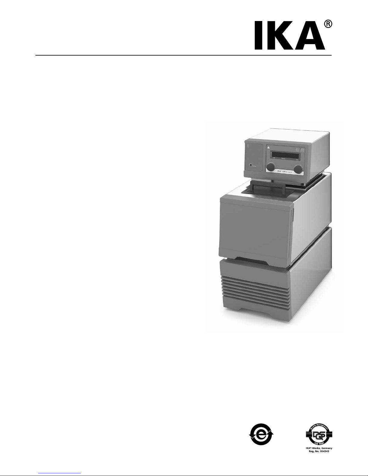
IKA® CBC 5 basic
CBC 5 basic_112016
Operating instructions EN
Page 2
2
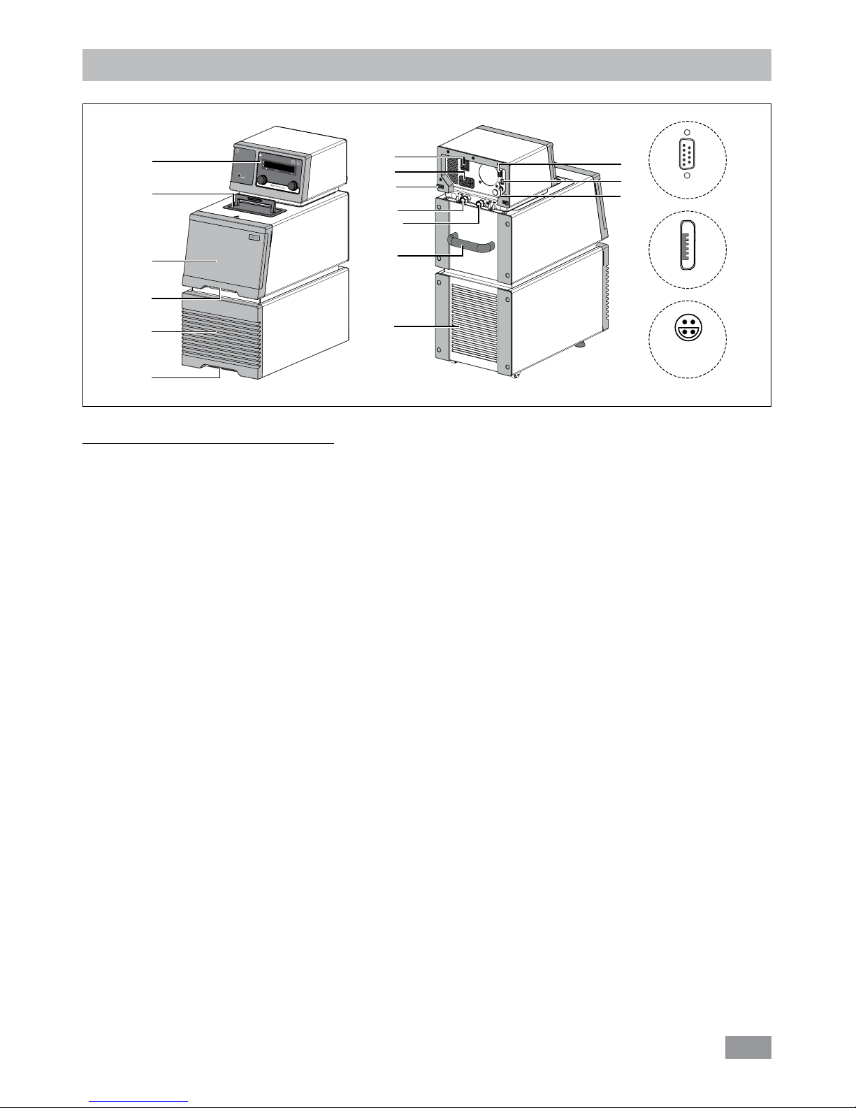
Item Designation
1 Operator panel and display
2 Filling opening lid
3 Front cover
4 Handle
5 Venting grid
6 Mains switch
7 Power socket
8 Cable clip
9 Pump connection IN
10 Pump connection OUT
11 RS 232 interface
12 USB interface
13 External temperature sensor socket
Device setup
Fig. 1
11
RS 232
13
ext
Pt 100
12
Micro USB
1
2
3
5
5
4
4
6
11
12
13
7
9
10
4
8
Page 3

3
Contents
EN
Source language: German
Page
Device setup ������������������������������������������������������������������������������������������������������������������������������������������������� 2
Declaration of Conformity ���������������������������������������������������������������������������������������������������������������������������� 4
Explication of warning symbols ������������������������������������������������������������������������������������������������������������������� 4
Safety instructions ��������������������������������������������������������������������������������������������������������������������������������������� 5
General information ����������������������������������������������������������������������������������������������������������������������������������������������5
Fluids ��������������������������������������������������������������������������������������������������������������������������������������������������������������������6
Correct use ��������������������������������������������������������������������������������������������������������������������������������������������������� 6
Use �����������������������������������������������������������������������������������������������������������������������������������������������������������������������6
Range of use (indoor use only) ������������������������������������������������������������������������������������������������������������������������������6
Unpacking ���������������������������������������������������������������������������������������������������������������������������������������������������� 7
Unpacking ������������������������������������������������������������������������������������������������������������������������������������������������������������7
Delivery scope �������������������������������������������������������������������������������������������������������������������������������������������������������7
Preparations ������������������������������������������������������������������������������������������������������������������������������������������������� 7
Setting up �������������������������������������������������������������������������������������������������������������������������������������������������������������7
Connecting the tubings �����������������������������������������������������������������������������������������������������������������������������������������7
Filling and draining ������������������������������������������������������������������������������������������������������������������������������������������������8
Fluids (Standard information for IKA® fluid) �����������������������������������������������������������������������������������������������������������9
Moving the device ����������������������������������������������������������������������������������������������������������������������������������������������10
Operator panel and display ������������������������������������������������������������������������������������������������������������������������ 10
Setting the safety temperature ������������������������������������������������������������������������������������������������������������������ 11
Commissioning ������������������������������������������������������������������������������������������������������������������������������������������� 11
Menu settings �������������������������������������������������������������������������������������������������������������������������������������������� 12
Menu structure ���������������������������������������������������������������������������������������������������������������������������������������������������12
Basic guide to setting the menu options ��������������������������������������������������������������������������������������������������������������13
Operating mode (MODE)�������������������������������������������������������������������������������������������������������������������������������������13
Maximum temperature (HI T) ������������������������������������������������������������������������������������������������������������������������������13
Minimum temperature (LO T) ������������������������������������������������������������������������������������������������������������������������������13
Maximum speed (HI R) ����������������������������������������������������������������������������������������������������������������������������������������13
Minimum speed (LO R) ����������������������������������������������������������������������������������������������������������������������������������������13
Fluid type (FLUI) ��������������������������������������������������������������������������������������������������������������������������������������������������13
Temperature control type (AUTO) (for heating) ����������������������������������������������������������������������������������������������������13
External and internal temperature control (ET) (for heating) ���������������������������������������������������������������������������������14
Alarm and key tone (BEEP) ����������������������������������������������������������������������������������������������������������������������������������14
Cooling (COOL)
����������������������������������������������������������������������������������������������������������������������������������������������������14
Calibration and adjustment (CALI) �����������������������������������������������������������������������������������������������������������������������14
Interface and output ���������������������������������������������������������������������������������������������������������������������������������� 15
Maintenance and cleaning ������������������������������������������������������������������������������������������������������������������������� 17
Error codes ������������������������������������������������������������������������������������������������������������������������������������������������� 18
Accessories ������������������������������������������������������������������������������������������������������������������������������������������������� 19
Technical data �������������������������������������������������������������������������������������������������������������������������������������������� 20
Warranty ���������������������������������������������������������������������������������������������������������������������������������������������������� 21
Pump performance curve ��������������������������������������������������������������������������������������������������������������������������� 21
Page 4
4
Declaration of Conformity
Explication of warning symbols
We declare under our sole responsibility that this product corresponds to the regulations 2014/35/EU, 2014/30/EU,
2014/53/EU and 2011/65/EU and conforms with the standards or other normative documents: EN 61010-1, EN 61010-2010, EN 61010-2-051, EN 61326-1, EN 60529 and DIN 12876-1�
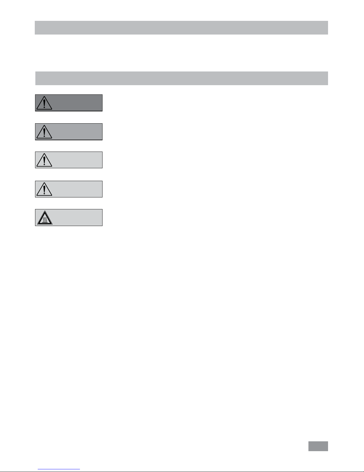
Indicates an (extremly) hazardous situation, which, if not avoided, will result in death,
serious injury�
Indicates a hazardous situation, which, if not avoided, can result in death, serious injury�
Indicates a potentially hazardous situation, which, if not avoided, can result in injury�
Indicates practices which, if not avoided, can result in equipment damage�
Indicates a hazardous situation that cause from a hot surface!
CAUTION
WARNING
CAUTION
NOTICE
DANGER
Page 5
5
Safety instructions
General information:
• Read the operating instructions completely before
starting up and follow the safety instructions�
• Keep the operating instructions in a place where it can be
accessed by everyone�
• Ensure that only trained staff work with the device�
• Follow the safety instructions, guidelines, occupational
health, safety and accident prevention regulations�
• Set up the device in a spacious area on an even, stable,
clean, non-slip, dry and fireproof surface�
• Do not operate the device in explosive atmospheres,
with
hazardous substances�
• Protect the device and accessories from bumping and impacting�
• Check the device and accessories for damage before each
use� Do not use damaged components�
• Safe operation is only guaranteed with the accessories described in the ”Accessories” section�
• The device must only be operated with the original mains
cord�
• The socket for the mains cord must be easily accessible�
• Socket must be earthed (protective ground contact)�
• The voltage stated on the type plate must correspond to
the mains voltage�
•
The device can only be disconnected from the mains supply
by pulling out the mains plug or the connector plug�
• Disconnect the mains plug before attaching or changing
any accessories�
• Disconnect the mains plug before cleaning, maintenance
or moving the device�
• The device must only be opened by trained specialists,
even during repair� The device must be unplugged from
the power supply before opening� Live parts inside the
device may still be live for some time after unplugging
from the power supply�
Coverings or parts that can be removed from the device must be put
back on the device again to ensure
safe operation, for example to keep foreign objects and
liquids, etc� from getting into the device�
• The device must only be used as prescribed and as described in the operating instructions� This includes operation by instructed specialist personnel�
• When using critical or hazardous materials in your processes, IKA® recommends to use additional appropriate
measures to ensure safety in the experiment� For example,
users can implement measures that inhibit fire or explosions or comprehensive monitoring equipment�
• Process pathogenic material only in closed vessels under a
suitable fume hood� Please contact IKA® application support if you have any question�
If the mains switch is not within
reach when device is operating, an
EMERGENCY STOP switch that
can be easily accessed must be installed in the work area�
• A laboratory circulator heats/refrigerates and circulates fluid according to specified parameters� This involves hazards
due to high temperatures, fire and general hazards due to
the device of electrical energy� The user safety can not be
ensured simply with design requirements on the part of
the device� Further hazard sources may arise due to the
type of tempering fluid, e�g� by exceeding or undercutting
certain temperature thresholds or by the breakage of the
container and reaction with the carrier fluid� It is not possible to consider all eventualities� They remain largely subject to the judgment and responsibility of the operator� For
this reason, it may become necessary for user to take other
precautionary safety measures�
• Insucient ventilation may result in the formation of explosive mixtures� Only use the device in well ventilated
areas�
The safety circuit (safe temperature)
must be adjusted so that the maxi-
mum permissible temperature cannot be exceeded even in the event of a fault� Check the
safe temperature circuit on a regular basis (see section
"Setting the safety temperature")�
• When device is used for external circulation, extra precaution must be taken for hot/cold liquid leakage due to
damaged hose�
- Use suitable hoses for connection�
- Secure hoses and tubes against slippage and avoid kinks�
- Check hoses, tubes and bath at regular intervals for possible material fatigue (cracks/leaks)�
• Mains cable should not get in contact with hot parts and
fluids�
Do not start up the device if:
- It is damaged or leaking
- Cable (not only mains cable) is
damaged�
• Be careful when filling a hot bath�
At high operating temperature, the
temperature of housing parts, surfaces and tubes can exceed 70 ° C�
It is dangerous to touch the heater�
The temperature of the heater can
be very high�
CAUTION
NOTICE
WARNING
WARNING
CAUTION
CAUTION
Page 6
6
• Continuous monitoring of the bath and the filling level of
the bath fluid is required, especially at high temperatures�
• To ensure a sucient fluid circulation, the viscosity of the
bath fluid must not exceed of 50mm2/s at the lowest operating temperature�
If water is used at higher temperature, there is heavy loss of fluid due
to the evaporation of the steam�
•
Untreated tap water is not recommended� It is recommended to use distilled water or high purity water (ion exchangers) and add 0�1 g soda (sodium carbonate Na2CO3)
/liter, to reduce corrosive properties�
Risk of burning caused by vapor or
hot water at the outlet of the cooling coil�
Don’t use following fluids:
- Untreated tap water
- Acids or bases
- Solutions with halides: chlorides, fluorides, bromides,
iodides or sulfur
- Bleach (Sodium Hypochlorite)
- Solution with chromates or chromium salts
- Glycerine
- Ferrous water�
When changing the bath fluid type,
must remove the remaining water
from the complete system (including hoses and external devices)� When doing this, also
open the stopper and union nuts caps of the pump outputs and inputs and blow compressed air through all the
pump outputs and inputs! Beware of the risk of burning
due to delay in boiling!
Correct use
• Use:
Use CBC 5 (Combined refrigerating and heating Bath Circulators) for heating/refrigerating and circulating fluids�
Intended Use: Tabletop device�
• Range of use (indoor use only):
- Laboratories - Schools
- Pharmacies - Universities
This device is suitable for use in all areas except:
- Residential areas
-
Areas that are connected directly to a low-voltage supply
network that also supplies residential areas�
The safety of the user cannot be guaranteed:
- if the device is operated with accessories that are not supplied or recommended by the manufacturer
- if the device is operated improperly or in contrary to the
manufacturer’s specifications
- if the device or the printed circuit board are modified by
third parties�
• After a power failure during operation, the device may
start automatically (depending on operating mode)�
• Transport the device with care�
• Do not transport or empty the bath while it is still hot/
cold� This may result in accidents, especially scalding injuries or frostbite�
Because of the heavy weight of the
device, at least two persons are
needed for carrying the device�
Fluids:
Beware of the risk of burning due
to delay in boiling!
Only use fluids, which fulfill the requirements for safety, health and
device compatibility� Be aware of
the chemical hazards that may be associated with the bath
fluid used� Observe all safety warnings for the fluids�
• Depending on the bath fluid used and the type of operation, toxic or flammable vapors can arise� Ensure suitable
extraction�
• Do not use any fluid which may cause dangerous reactions during processing�
• Only use recommended bath fluid� Only use non-acid and
non corroding fluid�
Only process and heat up any fluid
that has a flash point higher than
the adjusted safe temperature limit
that has been set� The safe temperature limit must always
be set to at least 25 ºC lower than the flash point of the
fluid used� Examine regularly the function of the safety
temperature limiter�
Never operate the device without
sucient heat carrier fluid! Check
the fluid level detection at a regular
basis (see the chapter “Filling and draining”)�
CAUTION
CAUTION
WARNING
WARNING
NOTICE
NOTICE
NOTICE
NOTICE
CAUTION
Page 7
7
Unpacking
• Unpacking:
- Please unpack the device carefully�
- In the case of any damage a detailed report must be
sent immediately (post, rail or forwarder)�
Transport safety:
Open the lid (2) and remove the
protection under the buoyage�
• Delivery scope:
-
CBC 5 baisc circulator
- Mains cables
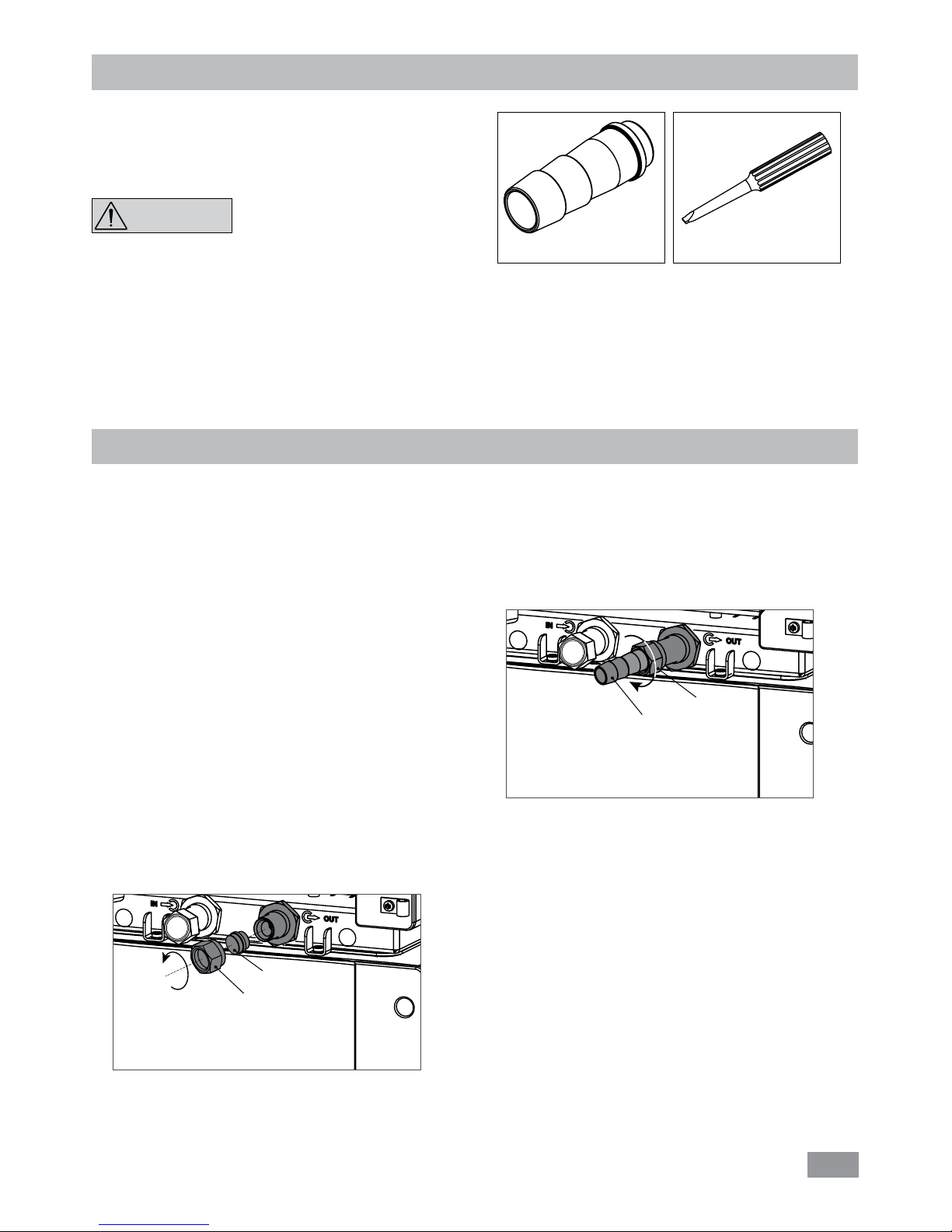
- Hose olive NW 12 (2 pieces) see Fig� 2
- Screwdriver (use for safety circuit) see Fig� 3
- User guide
- Warranty card�
Fig. 3Fig. 2
Preparations
• Setting up:
- Place the unit on an even, stable, clean, nonslip, dry and
fireproof surface�
- Keep at least 20 cm of open space on the front and rear
side�
- The place for installation should be large enough and
provide sucient air ventilation to ensure the room
does not warm up excessively because of the heat from
device radiates to the environment�
- Do not set up the device in the immediate vicinity of
heat sources and do not expose to sun light�
- Cooling machine, pump motor and electronics produce
intrinsic heat that is dissipated via the venting grids (5)!
Never cover these venting grids!
Note: After setting up the device, wait at least one hour before starting the operation to avoid the damage to the cooling system�
• Connecting the tubings:
Unscrew the union nuts and stoppers using a wrench
(SW 19) from the pump connection IN (9) and OUT (10)�
Stopper
Union nut
Fig. 4
NOTICE
- Connect the hoses for circulating the external system to
the pump connectors M 16 x 1 for IN and OUT directly or
with the olives�
- Screw the hose olive to the pump connection IN and OUT
with union nuts� Slide the hoses (NW 12) onto the olives�
The hoses must be secured with suitable clamps�
Note: Please note the permissible temperature range of
hoses� For hot fluids we recommend the IKA® LT 5�20
hoses�
When the external system is not necessary, please seal
the pump connectors IN and OUT with the existing union
nuts and stoppers�
Hose olive
Union nut
Fig. 5
Page 8
8
Fig. 7
Drain valve
Drain port
Fig. 8
Low level
High level
Note:
Pay attention to the fluid level information!:
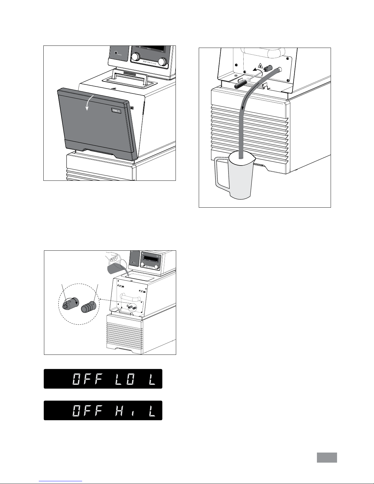
- To drain the fluid from the bath, connect a hose to the
drain port and turn the drain valve in counter clockwise
direction with a straight screwdriver�
- Check and make sure that the drain valve is closed (Rotate clockwise to the stop position, see Fig� 7)�
Note: Please note information in chapter “Commissioning”�
- Connect the mains plug and turn on the device with
mains switch (6)�
- The low level warning message appear on the display�
- Open the lid (2) and fill fluid to the bath�
• Filling and draining:
- Before filling the fluid into the bath, open the front cover
as indicated in following figure�
Fig. 6
Warning: do not empty the bath while it is still hot/cold,
there is a risk of burning/freezing�
Page 9

9
• Fluids (Standard information for IKA® fluid):
No�
IKA
®
Designation
Operating temperature
range for open bath
application
(°C)
Operating temperature
range for closed bath
applications
(°C)
Safety temperature
(°C)
Flash point
(°C)
0
CF�EG28�N10�80�8
-10 ��� 80 -10 … 80 90 115
1
CF�EG39�N20�80�16
-20 … 80 -20 … 80 90 115
2
CF�EG44�N25�80�19
-25 … 80 -25 … 80 90 115
3
CF�EG48�N30�80�22
-30 … 80 -30 … 80 90 115
4
UF�Si�N30�150�10LV
-30 … 130 -30 … 150
145
>170
5
HF�Si�20�200�50
20 … 200 20 … 200 255 >280
6
HF�Si�20�250�50A
20 … 200 20 … 250 255 >280
7
Water
5 … 95 5 … 95 - -
8
Customized
The listed fluid temperature range may deviate from the device operating temperature ranges and settings�
Note: for open bath application!
Note: Tap water may be unsuitable for operation because the calcium carbonate content may cause calcification�
High purity water (from icon exchangers) and distilled or bi-distilled water are unsuitable for operation due to corrosive
properties of these media� High purity water and distillates are suitable as a medium after adding 0�1 g soda (Na2CO3,
sodium carbonate) per liter of water�
Note: The temperature limit values are adjustable in accordance with the fluid used�
Nomenclaturefor IKA® fluids:
CF�EG28�N10�80�8 --
(1) Classification:
HF: Heating Fluid
CF: Cooling Fluid
UF: Universal Fluid
(2) Chemical composition:
Si: Silicone oil
EG: Ethylene Glycol
(3) Temperature range: (
Minimum temperature� Maximum temperature)
N: Negative Temperature
(4) Viscosiy:
Viscosiy at 25 °C for Heating Fluid (HF)
Viscosity at -20 °C for Cooling Fluid (CF)
Viscosity at 25 °C for Universal Fluid (UF)
Dynamic viscosity [mPa•s] is a product of kinematic viscosity [mm²/s] and density [kg/m³] of the fluid divided by 1000�
(5) Additional information:
A: Oil Additives
LV: Low Viscosity
(5) Addition information
(4) Viscosity (8
mm²/s
)
(3) Temperature range (-10 – 80 °C)
(2) Chemical composition (Ethylene Glycol 28%)
(1) Classification (Cooling fluid)
Page 10
10
Operator panel and display
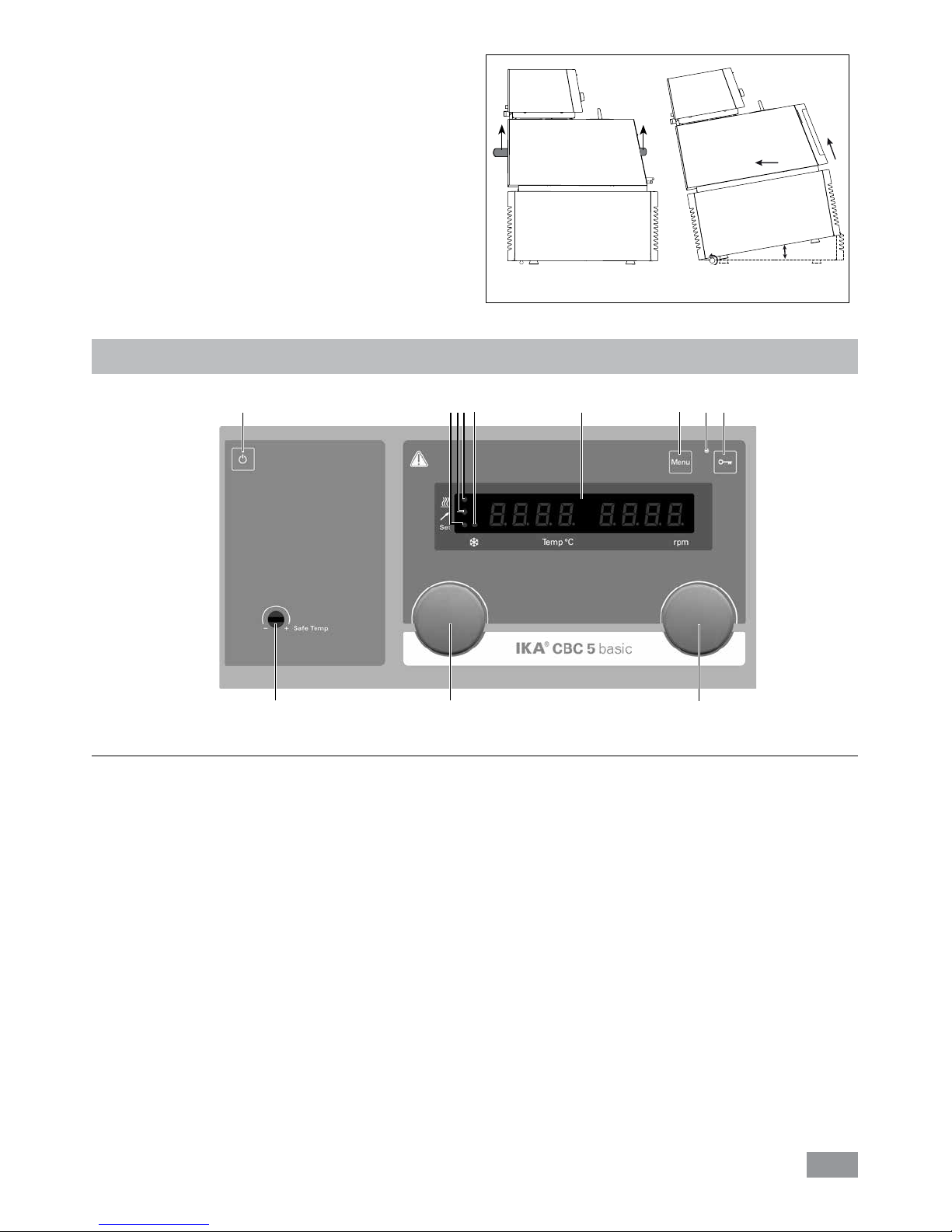
Item Designation Function
A On/Off key: Switch on/off the circulator�
B LED, set: The LED lights up at the same time as the set value is displayed�
C LED, temperature sensor:
Indicates that an external temperature sensor is connected�
D LED, heater:
Indicate the heating function is activated�
E LED, refrigerating system: Indicates that the refrigerating function is deactivated�
F LED display:
Display the settings and actual values�
G Menu key:
Press it once: menu option is display�
Press it a second time: back to the working screen�
H LED, lock: Indicates that the function of keys and knobs is deactivated�
I Lock key:
Lock/unlock keys and knobs�
J Rotating/pressing knob:
Set the pump speed value�
Start/stop the pump function�
K Rotating/pressing knob:
Set the temperature value�
Start/stop the heating/refrigerating function�
Navigation, selecting the settings in the menu�
Set and confirm the menu options�
L Adjustable safety circuit: Adjust the safety temperature limit�
• Moving the device:
Empty all fluid in the bath before moving device from one
place to other place�
The device must be lifted by two persons with the upper
handles� For this purpose, take off the front cover (3)�
It can also be moved on flat surface by lifting and pushing
the front of the device� It is easy to move the device with
the help of the wheels�
The angle of inclination should never be more than 10 º
at any direction when move the device!
Note: The device must not be moved during operation�
After moving the device, you must wait at least one hour
before restarting the unit�
Fig. 10
K J
A
L
CB DE
F
G H I
max. 10 ˚
Fig. 9
Page 11
11
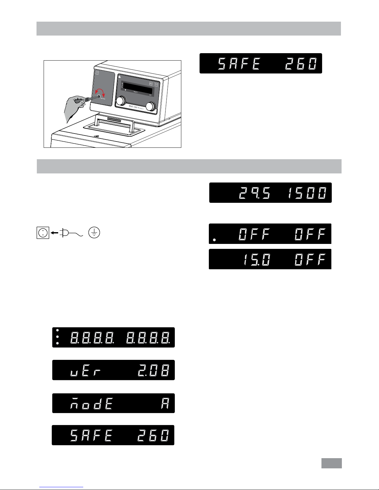
Note: Before commissioning, make sure that the device
has not been moved in one hour!
Check whether the voltage specified on the type plate
matches the mains voltage available�
The power socket used must be
earthed (protective earthing)�
If above conditions are met, the device is ready for operation after plugging in the mains plug�
If these conditions are not met, safe operation is not guaranteed and the device could be damaged�
Observe the ambient conditions (temperature, humidity,
etc�) listed under “Technical Data”�
After switching on the mains switch (6) at the back of the
device or pressing the on/off key (A), all LED segments light
up during the self test�
Commissioning
Then the device enters standby status and is ready for operation�
Change the temperature setting with left knob (K)�
Change the pump speed setting with the right knob (J)�
In standby status, activate the heating/refrigerating function by pressing the left knob (K)� The device start heating/
refrigerating function� Meanwhile, the pump and fan starts
to run at once�
After pressing the mains switch (6) the start-up of the compressor is delayed (about 3min)�
In working status, press the right knob (J) to stop the pump
function� The heating/refrigerating function and pump stops�
Note: In running status, the pump speed adjusts automatically according to the load� When the actual speed doesn’t
reach the setting speed, the actual speed and setting speed
will appear on the screen alternately�
In standby status, press the right knob (J) to start the pump
function� The heating/refrigerating function will not be activated�
In working status, press the left knob (K) to stop the heating/refrigerating function, the pump keep running�
Software version (ver)
Safety temperature
Working setting
Display field
Operating mode (mode)
After that, following two screens appear alternately�
Setting the safety temperature
Seting the safety temperature with screwdriver delivered
with the device�
The safety temperature setting will appear on the display�
Factory setting: approximate max� value�
Adjustment range: see “Technical data“�
Note: The safety temperature must always be set to at least
25 ºC lower than the flash point of the fluid used�
Safety temperature
Fig. 11
+
-
Page 12

12
Pressing the lock key (I) for about 2 seconds, the device control elements can be locked to prevent accidental changes
that can be done during operation
(LED (H) will light up)�
To unlock the control elements, press the lock key again for
about 2 seconds (LED (H) goes out)�
Note: When the heating function is activated, you can review the external/internal actual temperature on the right
of the display (speed display) by pressing the menu key (G)�
For details, see following table:
ET=0 ET=1 Temp. display rpm display
(pressing menu
key (G))
activated – internal control
temperature
external actual
temperature
–
activated
external control
temperature
internal actual
temperature
When ET=0, if external sensor is not connected, when
pressing menu key (G), the right display shows “- - - -”�
After pressing menu key (G) about 10 seconds, value in the
right display will change back and show pump speed�
When the heating/refrigerating function is activated, you
can enter the menu option by pressing
menu key (G) about
3 seconds�
Menu settings
MODE
Maximum temperature (HI T)
Minimum temperature (LO T)
Maximum speed (HI R)
Minimum speed (LO R)
Fluid type (FLUI)
The type of temperature PID control arithmetic (AUTO)
(heating)
External and internal temperature control (ET)
(heating)
Alarm and key tone (BEEP)
Cooling (COOL)
Menu
• Menu structure:
Default settings
A
B
C
Proportional coecient of PID (Kp 1)
Integrate time of PID (Ti 1)
Differential time of PID (Td 1)
AUTO 1
AUTO 0
External sampling time (EuT 2)
Proportional coecient of PID (Kp 2)
Integrate time of PID (Ti 2)
Differential time of PID (Td 2)
DF t
FASt 0
FASt 1
ET 0
ET 1
BEEP 0
BEEP 1
0
1
activated
-
-
200 °C
-25 °C
4600 rpm
1000 rpm
8
activated
15�0
5�00
5�0
activated
90 s
1�0
1�5
0�0
100�0
activated
activated
activated
activated
-
-
Note: DF t: maximum temperature difference between internal and external temperature�
Calibration (CALI)
CALI 0
CALI 2
CALI 3
Page 13
13
• Basic guide to setting the menu options:
F Enter the menu by pressing ”Menu” key (G)�
F Turn the left knob (K) to select a menu option�
F Turn the right knob (J) to change the menu value settings�
F Confirm the menu settings by pressing the right knob (J)�
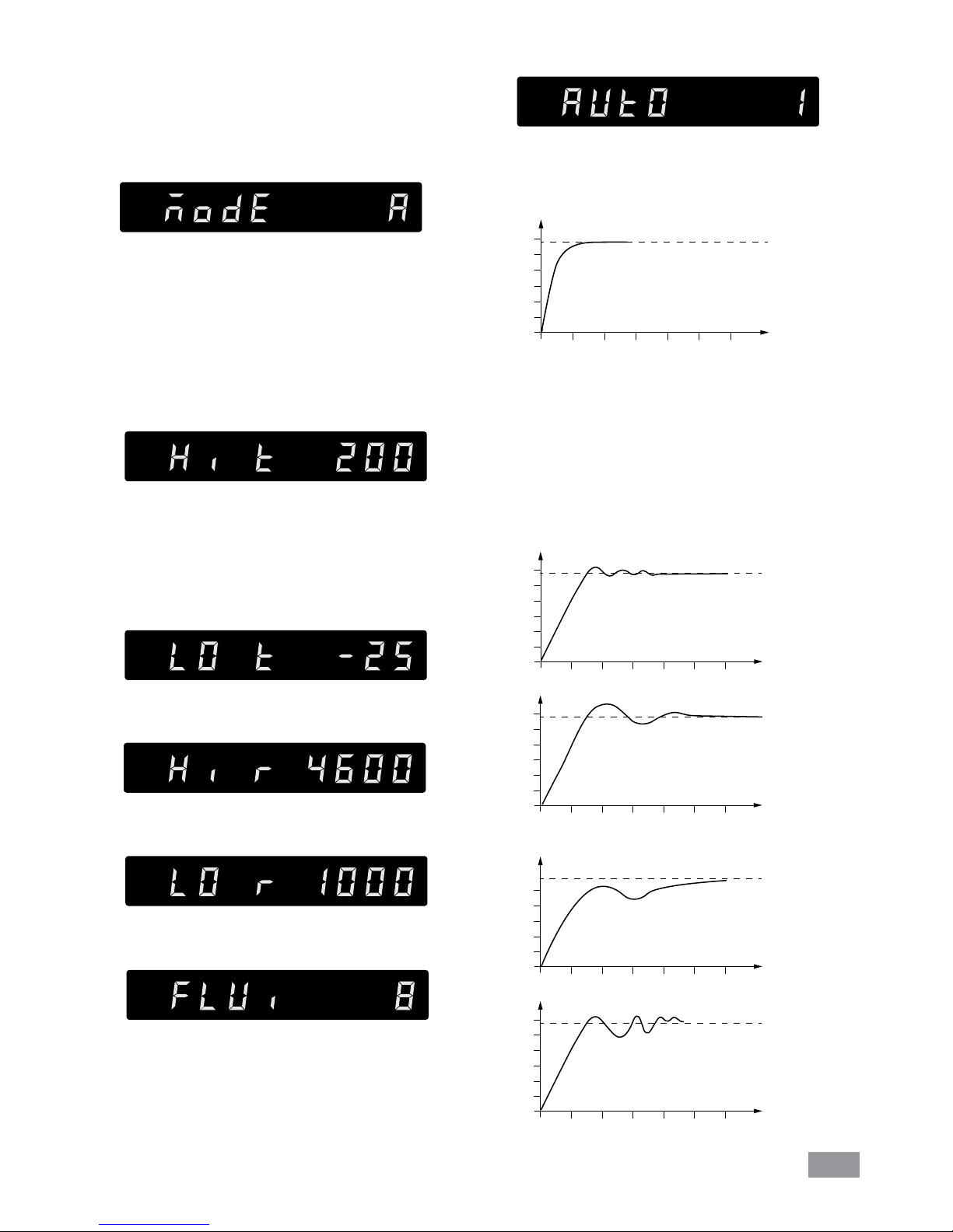
• Operating mode (MODE):
Mode A: After power on/power failure no automatic re-
start of functions�
Mode B: After power on/power failure automatic restart
of functions, depending on previous settings�
Mode
C:
Set values (set in A or B) cannot be changed�
After power on/power failure automatic restart of functions, depending on previous settings�
• Maximum temperature (HI T):
The maximum adjustable value: 200° C� This value can be
limited additionally by the selected fluid (No�, see “Fluid
(Standard information for IKA® fluid)” fluid type)�
Note: The maximum value is limited by the set safety
temperature�
• Minimum temperature (LO T):
The minimum adjustable value: -25° C
• Maximum speed (HI R):
The maximum adjustable value: 4600 rpm�
• Minimum speed (LO R):
The minimum adjustable value: 1000 rpm
• Fluid type (FLUI)
The chosen fluid (No�) of the temperature setting is limited� See Section “Fluid”�
• Temperature control type (AUTO) (heating):
AUTO 1:
AUTO 1 is the default setting� The optimum settings are
determined automatically�
Heating up curve in auto-tuning control (Auto 1):
°C
t
Fig. 12
AUTO 0:
For special requirements, AUTO 0 can be used with manual adjustment of the control parameters�
If the PID control (AUTO 0) option is selected, the following items including Kp 1, Ti 1 and Td 1 could be set�
Otherwise they are not displayed in the menu list�
Note: Inappropriate settings may produce the following
heating up curves:
Fig. 13
°C
t
Kp too high
°C
t
Ti too low
°C
t
Td too high
°C
t
Kp too low
Ti too high
Page 14
14
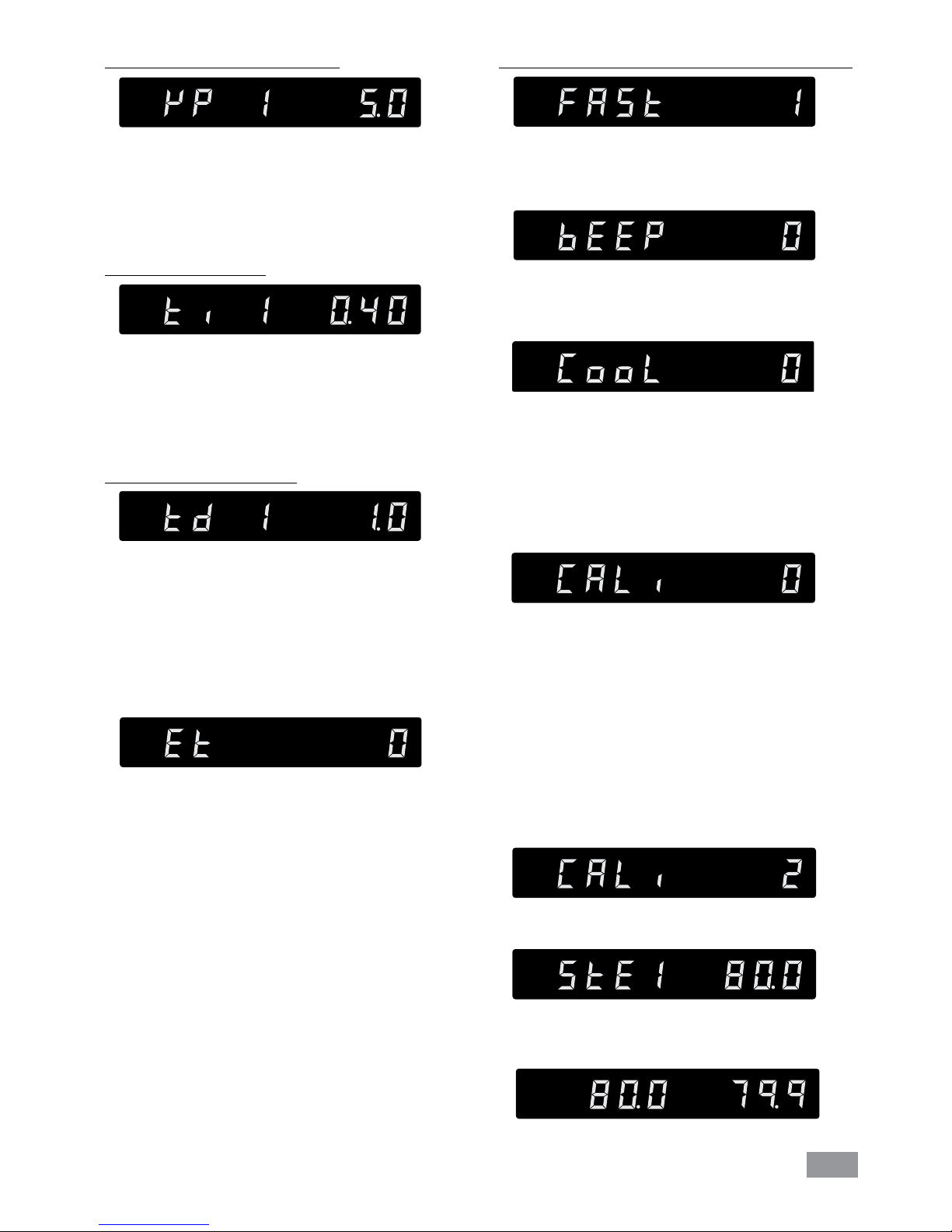
Proportional coecient of PID (Kp 1):
Integral time of PID (Ti 1):
Differential time of PID (Td 1):
The proportional coecient Kp is the controller amplification and determines how strongly the control deviation
(the difference between the target temperature and actual temperature) directly affects the control variable (ontime of the heater)� Kp values that are too large can lead
to the controller overshooting�
The integral time Ti (s) is the correction time and determines how strongly the duration of the control deviation
affects the control variable� Ti compensates an existing
control deviation� A high Ti means a smaller and slower
effect on the control variable� Ti values that are too small
can lead to instability of the controller�
The differential time Td (s) is the derivative time and determines how strongly the rate of change of the control
deviation affects the control variable� Td compensates for
rapid control deviations� A high Td means a smaller and
slower effect on the control variable� Td values that are
too small can lead to instability of the controller�
•
External and internal temperature control (ET)
(heating):
ET 0: internal temperature control
ET 1: external temperature control
If the external temperature control (ET 1) is selected, the
following items EuT 2 (sampling time), Kp 2, Ti 2, Td 2,
Df t (maximum temperature difference between internal
and external temperature) and FAST could be set� Otherwise they are not displayed in the menu list�
The sampling time EuT 2 (s) is the interval over which
the external control deviation and the respective control
variable (dependent on Kp 2, Ti 2, Td 2, Df t and FAST)
is determined�
EuT 2 must be adjusted to match the response characteristic (total of all time constants) of the external closed
loop controlled system, so that the control variable can
deliver a uniform and measurable change in the control
deviation� EuT 2 values that are too small or too large
can lead to instability of the controller�
Dynamics of the external PID temperature control (FAST):
FAST=0: accurate, without overshoot
FAST=1: fast, with overshoot
•
Alarm and key tone (BEEP):
BEEP 0: no alarm and key tone
BEEP 1: alarm and key tone is activated
•
Calibration and adjustment (CALI):
CALI 0: Reset calibration
CALI 2: 2-point calibration
CALI 3: 3-point calibration
Example: 2-point calibration:
Dip the temperature sensor of the reference measuring
device into the bath fluid:
- If ET 0: into the internal bath (open the lid (2))
- If ET 1: at the same position as the external Pt100
temperature sensor (13)�
If ET 0: adjustment of the internal temperature measurement�
If ET 1: adjustment of the external temperature measurement�
Set the first point temperature (e�g� 80 °C)� Confirm the
setting by pressing the right knob (J)�
Left area of the display appears the set value (80 °C) and
the right area of the display appears the actual temperature value measured� The “Set” LED (B) flashes briefly�
Select 2-point calibration in the menu� Press the right
knob (J) to start the 2-point calibration�
•
Cooling (COOL):
0: Cooling function is deactivated�
1: Cooling function is activated�
Page 15
15
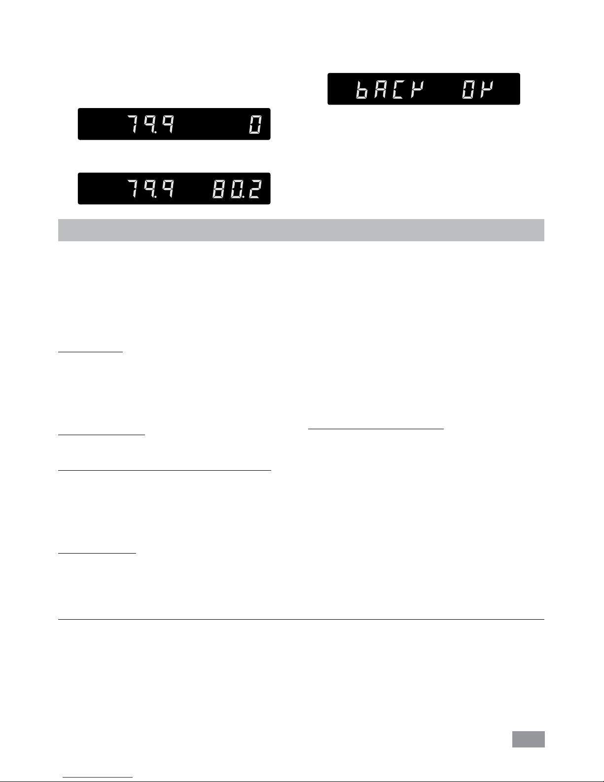
The unit now starts and controls to the set value� When
the temperature has reached the set value and has become constant, the “Set” LED (B) no longer flashes and
the following display appears�
The temperature measured by the unit appears on the
left hand side�
Input the calibration value from the reference mesuring
device (e�g� 80�2 °C) with the right knob (J)�
Confirm the value by pressing the right knob (J)�
Back to previous screen for input a new value by pressing
the left knob (K)�
Back OK
The first point calibration is finished now�
Calibration of the other points is performed in the same
way�
Interface and output
The device can be operated in “Remote” mode via the RS 232
interface (11) or the USB interface (12) connected to a PC and
with the laboratory software Labworldsoft®�
Note: Please comply with the system requirements together with the operating instructions and help section included
with the software�
USB interface:
The Universal Serial Bus (USB) is a serial bus for connecting
the device to the PC� Equipped with USB devices can be connected to a PC during operation (hot plugging)� Connected
devices and their properties are automatically recognized�
The USB interface can also be used to update firmware�
USB device drivers:
First download the latest driver from IKA® devices with USB
interface from:
http://www.ika.com/ika/lws/download/usb-driver.zip.
Install the driver by running the setup file� Then connect the
IKA® device through the USB data cable to the PC�
The data communication is via a virtual COM port�
Configuration, command syntax and commands of the virtual COM ports are as described in RS 232 interface�
RS 232 interface:
Configuration
- The functions of the interface connections between the
stirrer machine and the automation system are chosen
from the signals specified in EIA standard RS 232 in accordance with DIN 66 020 Part 1�
- For the electrical characteristics of the interface and the allocation of signal status, standard RS 232 applies in accordance with DIN 66 259 Part 1�
- Transmission procedure: asynchronous character transmission in start-stop mode�
- Type of transmission: full duplex�
- Character format: character representation in accordance
with data format in DIN 66 022 for start-stop mode� 1
start bit; 7 character bits; 1 parity bit (even); 1 stop bit�
- Transmission speed: 9600 bit/s�
- Data flow control: none
- Access procedure: data transfer from the stirrer machine to
the computer takes place only at the computer’s request�
Command syntax and format:
The following applies to the command set:
- Commands are generally sent from the computer (Master)
to the device (Slave)�
- The device sends only at the computer’s request� Even
fault indications cannot be sent spontaneously from the
device to the computer (automation system)�
- Commands are transmitted in capital letters�
- Commands and parameters including successive parameters are separated by at least one space (Code: hex 0x20)�
- Each individual command (incl� parameters and data) and
each response are terminated with CR LF (Code: hex 0x0d
hex 0x0A) and have a maximum length of 80 characters�
- The decimal separator in a number is a dot (Code: hex
0x2E)�
The above details correspond as far as possible to the recommendations of the NAMUR working party (NAMUR recommendations for the design of electrical plug connections for analogue and digital signal transmission on individual items of laboratory
control equipment, rev� 1�1)�
The NAMUR commands and the additional specific IKA® co mmands serve only as low level commands for communication
between the device and the PC� With a suitable terminal or communications programme these commands can be transmitted
directly to the circulator equipment� The IKA® software package, Labworldsoft®, provides a convenient tool for controlling
circulating equipment and collecting data under MS Windows, and includes graphical entry features, for pump motor speed
ramps for example�
The following table summarizes the (NAMUR) commands understood by the IKA® control equipment�
Page 16
16
Commands:
NAMUR
Commands
Function
IN_PV_1 Read the external actual temperature
IN_PV_2 Read the internal actual temperature
IN_PV_3 Read the safety actual temperature
IN_PV_4 Read the pump actual speed
IN_SP_1 Read the internal setting temperature (if ET=0)
Read the external setting temperature (if ET=1)
IN_SP_3 Read the safety setting temperature
IN_SP_4 Read the pump setting speed
IN_TMODE Read temperature control
0: internal regulation
1: external regulation
OUT_SP_1 xxx Set the internal setting temperature XXX (if ET=0)
Set the external setting temperature XXX (if ET=1)
OUT_SP_12@n Set the WD safety temperature with echo of the set (defined) value�
OUT_SP_4 xxx Set the pump speed XXX
OUT_SP_42@n Set the WD-safety speed with echo of the set (defined) value�
OUT_TMODE_0 Set to Internal temperature control
OUT_TMODE_1 Set to External temperature control
OUT_WD1@n Start the watchdog mode 1 and set the time for the watchdog to n (20���1500) seconds�
Echo of the Watchdog time�
During a WD1-event, the heating and pump functions are switched off�
This command needs to be send within the watchdog time�
OUT_WD2@n Start the watchdog mode 2 and set the watchdog time to n (20���1500) seconds�
Echo of the watchdog time�
During a WD2-event, the set temperature is changed to the WD safety temperature and the pump set
speed is set to the WD safety speed�
This command needs to be send within the watchdog time�
RESET Reset the PC control and stop the device functions�
START_1 Start the tempering function
START_4 Start the pump function
STOP_1 Stop the tempering function
STOP_4 Stop the pump function
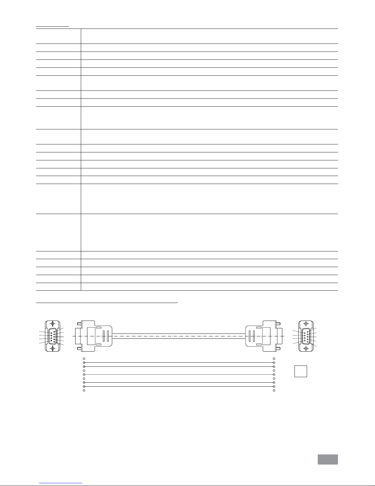
PC 1�1 Cable: This cable is required to connect RS 232 interface (11) to a PC�
1
2 RxD
3 TxD
4
5 GND
6
7 RTS
8 CTS
9
1
RxD 2
TxD 3
4
GND 5
6
RTS 7
CTS 8
9
PC
1
2
3
4
5
6
7
8
9
9
8
7
6
5
4
3
2
1
Fig. 14
Connections between device and external devices:
Page 17
17
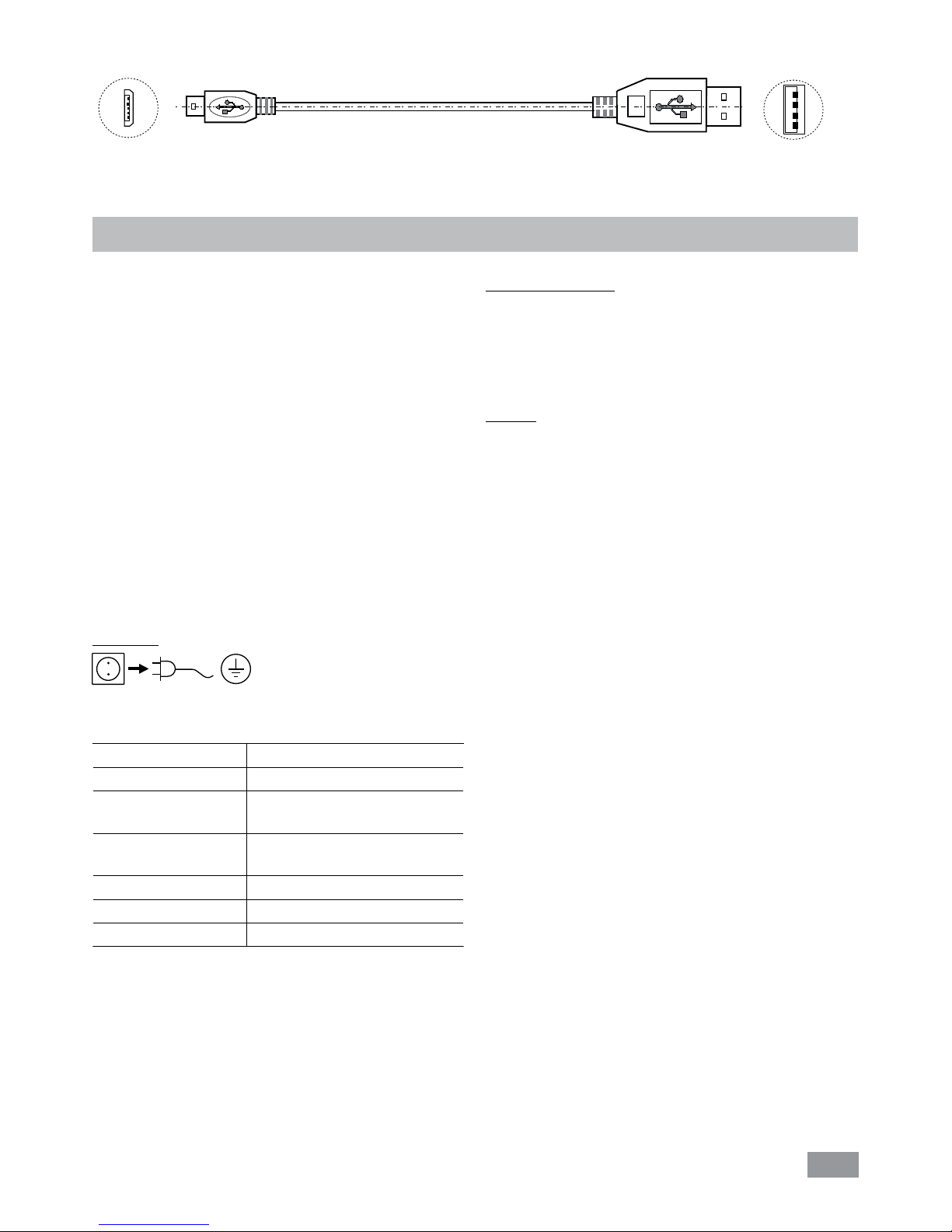
USB 2�0 cable A - Micro B: This cable is required to connect USB interface (12) to a PC�
USB micro B
USB A
A
Fig. 15
Maintenance and cleaning
To avoid contamination, it is essential to change the bath
fluid from time to time�
If water is used for bath fluid, we recommend to add Water bath protective media� The protective media stops the
growth of algae, bacteria and other microorganisms with
its bactericidal effectiveness� It protects the bath fluid and
provides a long period of use for the fluid�
To keep the full cooling performance, the dust filter of the
cooler must be checked regularly and cleaned if necessary�
• Switch off the device and disconnect mains cable�
• Open the front venting grid (5)�
• Remove the bracket�
• Clean condenser dust protection sheet with a vacuum
cleaner or wash the sheet in the water and dry the sheet
before assembly�
Note: Don’t touch the condenser surface with hard parts�
Cleaning:
Disconnect main plug prior to
cleaning!
Use only cleaning agents which have been approved by
IKA® to clean the device�
Dirt Cleaning agent
Dye Isopropyl alcohol
Construction material
Water containing tenside/
isopropyl alcohol
Cosmetics
Water containing tenside/
isopropyl alcohol
isopropyl alcohol
Water containing tenside
Foodstuff
Water containing tenside
Fuel Water containing tenside
For materials which are not listed, please request information from IKA® application support�
Wear protective gloves while cleaning the devices�
Electrical devices may not be placed in the cleansing agent
for the purpose of cleaning�
Do not allow moisture to get into the device when cleaning�
If a different cleaning or decontamination method than the
method defined by IKA® is planned, the user must ascertain
with IKA® that this method does not damage the device�
Spare parts order:
When ordering spare parts, please give:
- machine type
- manufacturing number, see type plate
- item and designation of the spare parts,
see www�ika�com
- software version�
Repair:
Please send in device for repair only after it has been
cleaned and is free from any materials which may
constitute a health hazard�
For repair, please request the “Decontamination Clearance
Certificate” from IKA®, or download printout of it from the
IKA® website www�ika�com�
If you require servicing, return the device in its original packaging� Storage packaging is not sucient� Please also use
suitable transport packaging�
Page 18
18
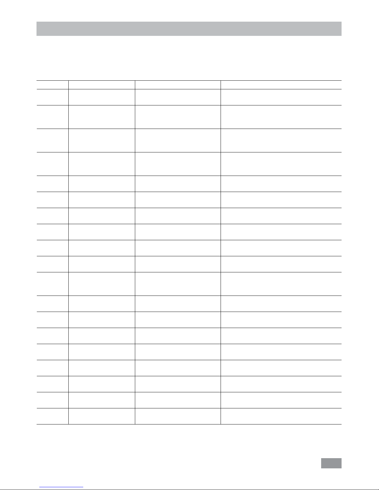
Error codes
Any malfunctions during operation will be identified by an error message on the display�
Proceed as follows in such cases:
- Switch off device using the main switch at the back of the device
- Carry out corrective measures
- Restart device
Error code Effect Cause Solution
Err 01 Pump off
Heating/refrigerating off
No external sensor - Check this sensor
Err 02 Pump off
Heating/refrigerating off
Motor over current (rate current)
- Reduce pump motor speed
- Use fluid with lower viscosity
- Check if the pump impeller is blocked
Err 03 Pump off
Heating/refrigerating off
Motor over current (Max current)
- Reduce pump motor speed
- Use fluid with lower viscosity
- Check if the pump impeller is blocked
Err 04 Pump off
Heating/refrigerating off
Motor hall signal missing - Reduce pump motor speed
- Use fluid with lower viscosity
- Check if the pump impeller is blocked
Err 05 Pump off
Heating/refrigerating off
Too high liquid level - Check the liquid level and buoyage
Err 06 Pump off
Heating/refrigerating off
Too low liquid level - Check the liquid level and buoyage
Err 07 Pump off
Heating/refrigerating off
Too high voltage - Check the mains power
Err 08 Pump off
Heating/refrigerating off
Too low voltage - Check the mains power
Err 09 Pump off
Heating/refrigerating off
Device internal temperature is
too high
- Check the ambient temperature and let the
device cool down
Err 10 Pump off
Heating/refrigerating off
PC communication failure - Check communication cable
- Check the fan and clean the grids at the rear side
Err 11 Pump off
Heating/refrigerating off
Temperature difference
between control sensor and
safety sensor is too much
- Check safety temperature circuit and bath
fluid
Err 12 Pump off
Heating/refrigerating off
Safety temperature alarm
- Check the bath temperature measurement
Err 13 Pump off
Heating/refrigerating off
Heater switched off by safety
circuit
- Check safety temperature set value, fluid
level
Err 14 Pump off
Heating/refrigerating off
Fan error - Restart the device
Err 15 Pump off
Heating/refrigerating off
Safety shutdown of the
compressor
- Restart the device
Err 16 Pump off
Heating/refrigerating off
Errors at the compressor
(suction side)
- Restart the device
Err 17 Pump off
Heating/refrigerating off
Errors at the compressor
(pressure side)
- Restart the device
Err 20 Pump off
Heating/refrigerating off
Fan cooling system error - Restart the device
Err 21 Pump off
Heating/refrigerating off
Internal error - Restart the device
If the actions described fails to resolve the fault or another error code is displayed then take one of the following steps:
- Contact the service department
- Send the device for repair, including a short description of the fault�
Page 19

19
Accessories
Tubing and hoses:
LT 5�20 Metal hose (isolated M16 x 1)
LT 5�21 PTFE hose (isolated M16 x 1)
H�PVC�8 PVC tube (nominal width 8 mm)
H�PVC�12 PVC tube (nominal width 12 mm)
H�SI�8 Silicone tube (nominal width 8 mm)
H�SI�12 Silicone tube (nominal width 12 mm)
H�PUR�8 PUR tube (nominal width 8 mm
)
H�PUR�12 PUR tube (nominal width
12 mm)
H�FKM�8 FKM tube (nominal width
8 mm)
H�FKM�12 FKM tube (nominal width
12 mm)
Tubing insulations:
ISO� 8 Insulation (8 mm)
ISO�12 Insulation (12 mm)
See more accessories on www.ika.com�
Valve:
MV 1 Magnetic valve
CO V 1 Closed pressure valve
Additional accessories:
Pt 100�30 Temperature sensor
PC 1�1 Cable (RS 232)
USB 2�0 cabel A - Micro B
Labworldsoft
®
Page 20
20
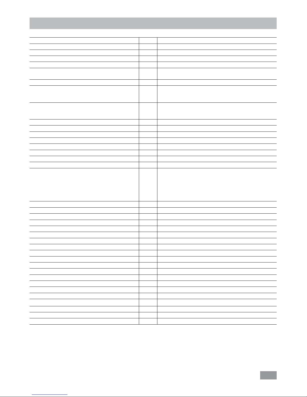
Technical data
Operating voltage VAC 230 ± 10 % / 100–115 ± 10 %
Frequency Hz 50 / 60
Max� input power W 3000 (230 VAC) / 1750 (115 VAC)
Working temperature range °C - 25 ��� + 200
Operating temperature range °C - 25 ��� + 200
Temperature stability – internal temperature control 70 °C,
water (according to DIN 12876)
K ± 0�02
Temperature control PID
Temperature measurement, absolute accuracy
Internal (int) (adjustable by calibration)
External (ext) (adjustable by calibration)
K
K
± 0�2
± 0�2
External Pt 100�3 temperature sensor tolerance to EN 60751
class A, ≤ ± (0�15 + 0�002 x |T|), e�g� at max� 100 °C
(adjustable by calibration)
K ± 0�35 (at 100 °C)
Temperature setting Knob
Temperature setting resolution K 0�1
Temperature display LED
Temperature display resolution K 0�1
Classification according to DIN 12876-1
Class III (FL) suitable for flammable and non-flammable fluids
Safety circuit (adjustable) °C 0 ��� + 260
Safety temperature display LED
Heating capacity W
2500 (230 VAC) / 1250 (115 VAC)
Cooling capacity according to DIN 12876
(at 4600 rpm)
:
+ 20 °C
+ 10 °C
0 °C
- 10 °C
- 20 °C
W
350 (400 W at 3200 rpm)
320 (370 W at 3200 rpm)
270 (320 W at 3200 rpm)
190 (240 W at 3200 rpm)
80 (130 W at 3200 rpm)
Refrigerant
R134a
Refrigerant quantity g 230
Max� refrigerating system pressure bar 20
Pump speed rpm 1000 ��� 4600
Max� pump pressure/suction bar
0�61 / 0�45
Max� flow rate (at 0 bar) l/min 31
Bath volume I 5–7
Fluid maximum viscosity mm
2
/s 50
Sub-level protection Yes
Interface USB, RS 232
Permitted on-time % 100
Protection class according to EN 60 529 IP 21
Protection class I
Excess voltage category II
Contamination level 2
Permitted ambient temperature °C + 5 ��� + 32
Permitted ambient humidity % 80
Dimension (W x D x H) mm 275 x 490 x 635
Weight kg 39�5
Operation at a terrestrial altitude m max� 2000
Note: Refrigerant must be disposed of in accordance with local and national regulations�
Note: Complies to EN61000-3-11 subject to conditional connection: Zmax = 0�13 Ω� If necessary, consult your electricity supplier�
Subject to technical changes!
Page 21
21
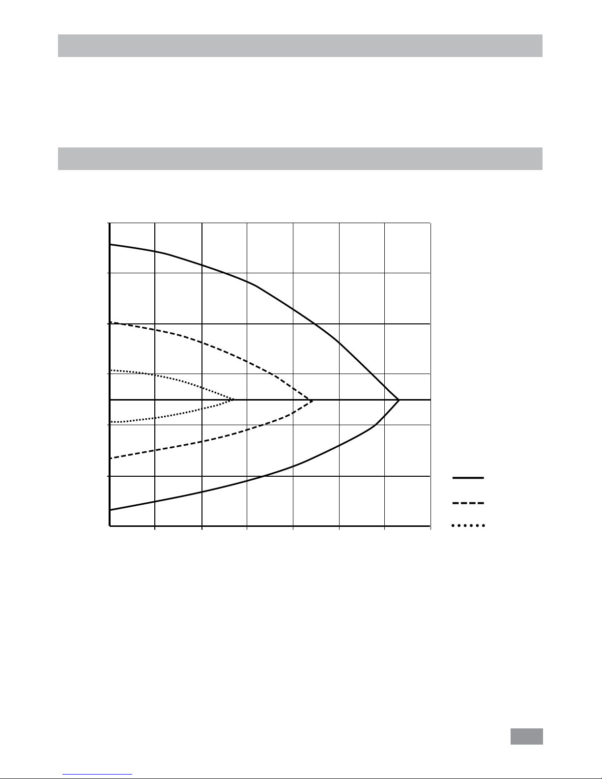
Pump performance curve
Pump performance curve measured with water:
(Measurements done according DIN 12876-2 with water at 20°C; pump in a closed-loop circuit)�
Fig. 16
Q [l/min]
ΔP [mbar]
4600 rpm
3200 rpm
2000 rpm
0 5 10 15 20 25 30 35
0
100
300
500
700
-100
-300
-500
Warranty
In accordance with IKA® warranty conditions, the warranty
period is 24 months� For claims under the warranty please
contact your local dealer� You may also send the machine
direct to our factory, enclosing the delivery invoice and giving reasons for the claim� You will be liable for freight costs�
The warranty does not cover worn out parts, nor does it apply to faults resulting from improper use, insucient care or
maintenance not carried out in accordance with the instructions in this operating manual�
Page 22

IKA®-Werke GmbH & Co�KG
Janke & Kunkel-Str� 10
D-79219 Staufen
Tel� +49 7633 831-0
Fax +49 7633 831-98
sales@ika�de
www�ika�com
 Loading...