


PPC-5xxx-9455 Panel PC
Revision
Date |
Version |
Changes |
|
|
|
August, 2008 |
1.00 |
Initial release |
|
|
|
Page ii

PPC-5xxx-9455 Panel PC
Copyright
COPYRIGHT NOTICE
The information in this document is subject to change without prior notice in order to improve reliability, design and function and does not represent a commitment on the part of the manufacturer.
In no event will the manufacturer be liable for direct, indirect, special, incidental, or consequential damages arising out of the use or inability to use the product or documentation, even if advised of the possibility of such damages.
This document contains proprietary information protected by copyright. All rights are reserved. No part of this manual may be reproduced by any mechanical, electronic, or other means in any form without prior written permission of the manufacturer.
TRADEMARKS
All registered trademarks and product names mentioned herein are used for identification purposes only and may be trademarks and/or registered trademarks of their respective owners.
Page iii

PPC-5xxx-9455 Panel PC
Manual Conventions
 WARNING!
Warnings appear where overlooked details may cause damage to the equipment or result in personal injury. Warnings should be taken seriously. Warnings are easy to recognize. The word “warning” is written as “WARNING,” both capitalized and bold and is followed by text. The text is the warning message. A warning message is shown below:
 WARNING:
This is an example of a warning message. Failure to adhere to warning messages may result in permanent damage to the PPC-5xxx-9455 or personal injury to the user. Please take warning messages seriously.
 CAUTION!
Cautionary messages should also be heeded to help reduce the chance of losing data or damaging the PPC-5xxx-9455. Cautions are easy to recognize. The word “caution” is written as “CAUTION,” both capitalized and bold and is followed. The text is the cautionary message. A caution message is shown below:
 CAUTION:
This is an example of a caution message. Failure to adhere to cautions messages may result in permanent damage to the PPC-5xxx-9455. Please take caution messages seriously.
Page iv
PPC-5xxx-9455 Panel PC
 NOTE:
NOTE:
These messages inform the reader of essential but non-critical information. These messages should be read carefully as any directions or instructions contained therein can help avoid making mistakes. Notes are easy to recognize. The word “note” is written as “NOTE,” both capitalized and bold and is followed by text. The text is the cautionary message. A note message is shown below:
 NOTE:
NOTE:
This is an example of a note message. Notes should always be read. Notes contain critical information about the PPC-5xxx-9455. Please take note messages seriously.
Page v

PPC-5xxx-9455 Panel PC
Packing List
 NOTE:
NOTE:
If any of the components listed in the checklist below are missing, please do not proceed with the installation. Contact the IEI reseller or vendor you purchased the PPC-5xxx-9455 from or contact an IEI sales representative directly. To contact an IEI sales representative, please send an email to sales@iei.com.tw.
The items listed below should all be included in the PPC-5xxx-9455 package.
1 x PPC-5xxx-9455
1 x Hard drive bracket
1 x IDE cable (40-pin to 40-pin) 1 x IDE cable (44-pin to 44-pin) 1 x Jumper pack
1 x Wall mounting kit
1 x Power cord
1 x Screw set
1 x IDE adapter for slim-type optical drive 1 x Utility CD
1 x QIG (quick installation guide)
Images of the above items are shown in Chapter 3.
Page vi

PPC-5xxx-9455 Panel PC
Table of Contents |
|
1 INTRODUCTION.......................................................................................................... |
1 |
1.1 GENERAL OVERVIEW ................................................................................................. |
2 |
1.1.1 PPC-5xxx-9455 Model Variations ..................................................................... |
2 |
1.1.2 Applications ....................................................................................................... |
3 |
1.1.3 Features ............................................................................................................. |
3 |
1.2 EXTERNAL OVERVIEW ............................................................................................... |
4 |
1.2.1 Front Panel ........................................................................................................ |
4 |
1.2.2 Rear Panel ......................................................................................................... |
5 |
1.2.3 Top Panel ........................................................................................................... |
5 |
1.2.4 Bottom Panel...................................................................................................... |
6 |
1.2.5 Left Panel ........................................................................................................... |
7 |
1.2.6 Right Panel......................................................................................................... |
7 |
1.3 INTERNAL OVERVIEW................................................................................................. |
8 |
2 SPECIFICATIONS........................................................................................................ |
9 |
2.1 INTRODUCTION ........................................................................................................ |
10 |
2.1.1 System Specifications ....................................................................................... |
10 |
2.1.2 Motherboard Specifications............................................................................. |
12 |
2.1.3 Flat Panel Screen............................................................................................. |
13 |
2.1.3.1 PPC-5150A-9455 Screen .......................................................................... |
13 |
2.1.3.2 PPC-5170A-9455 Screen .......................................................................... |
14 |
2.1.3.3 PPC-5190A-9455 Screen .......................................................................... |
15 |
2.1.4 Power Supply ................................................................................................... |
16 |
2.1.4.1 ACE-4518AP Power Supply..................................................................... |
17 |
2.1.4.2 ACE-4520C Power Supply ....................................................................... |
18 |
2.2 DIMENSIONS ............................................................................................................ |
18 |
2.2.1 PPC-5150A-9455 Dimensions ......................................................................... |
19 |
2.2.2 PPC-5170A-9455 Dimensions ......................................................................... |
20 |
2.2.3 PPC-5190A-9455 Dimensions ......................................................................... |
21 |
2.3 MOTHERBOARD ....................................................................................................... |
22 |
2.4 CPU SUPPORT.......................................................................................................... |
22 |
Page vii

|
|
PPC-5xxx-9455 Panel PC |
2.5 |
SYSTEM CHIPSETS.................................................................................................... |
22 |
2.5.1 Intel® 945G Northbridge Chipset ................................................................... |
23 |
|
2.5.2 ICH7 Southbridge Chipset............................................................................... |
23 |
|
2.6 GRAPHICS SUPPORT ................................................................................................. |
24 |
|
2.6.1 Analog CRT Support ........................................................................................ |
25 |
|
2.6.2 LVDS Support .................................................................................................. |
25 |
|
2.7 MEMORY.................................................................................................................. |
25 |
|
2.8 |
STORAGE.................................................................................................................. |
26 |
2.8.1 CompactFlash® ................................................................................................ |
26 |
|
2.8.2 SATA Hard Drive.............................................................................................. |
27 |
|
2.9 |
EXPANSION SLOTS ................................................................................................... |
28 |
2.10 EXTERNAL DEVICE CONNECTORS .......................................................................... |
29 |
|
2.10.1 USB 2.0 Ports................................................................................................. |
29 |
|
2.10.2 Serial Ports .................................................................................................... |
30 |
|
2.10.3 Parallel Port .................................................................................................. |
30 |
|
2.11 GIGABIT ETHERNET ............................................................................................... |
31 |
|
2.12 FRONT PANEL......................................................................................................... |
31 |
|
2.12.1 Flat Screen ..................................................................................................... |
32 |
|
2.12.2 Touch Screen .................................................................................................. |
32 |
|
2.13 OEM OPTIONS....................................................................................................... |
32 |
|
3 UNPACKING ............................................................................................................... |
33 |
|
3.1 ANTI-STATIC PRECAUTIONS...................................................................................... |
34 |
|
3.2 UNPACKING PRECAUTIONS....................................................................................... |
34 |
|
3.3 |
PACKAGE CONTENTS................................................................................................ |
35 |
4 INSTALLATION AND CONFIGURATION ............................................................ |
37 |
|
4.1 |
INSTALLATION PRECAUTIONS................................................................................... |
38 |
4.2 |
PREINSTALLED COMPONENTS .................................................................................. |
38 |
4.3 |
INSTALLATION AND CONFIGURATION STEPS ............................................................. |
39 |
4.4 REMOVE THE BACK COVER...................................................................................... |
40 |
|
4.5 |
JUMPER SETTINGS.................................................................................................... |
41 |
4.5.1 AT/ATX Power Selection (AT_PWR_SW1) ...................................................... |
42 |
|
4.5.2 Clear CMOS Setup (JP2)................................................................................. |
42 |
|
4.5.3 Monitor Setup (JP1)......................................................................................... |
43 |
|
Page viii

PPC-5xxx-9455 Panel PC |
|
4.5.4 CF Card Setup (JP7)........................................................................................ |
44 |
4.5.5 COM Port RI and Voltage Selection (JP3, JP4, JP5, JP6, JP8) ..................... |
44 |
4.5.6 COM5 RS-232/422/485 Settings ...................................................................... |
45 |
4.5.6.1 COM5 RS-232/422/485 RX Select (J2) ................................................... |
45 |
4.5.6.2 COM5 RS-422/485 TX Select (J3)........................................................... |
45 |
4.5.6.3 COM5 D-Sub Pinout Selection (J4) ......................................................... |
46 |
4.5.6.4 COM5 Termination Resistors (J5, J6)....................................................... |
46 |
4.5.7 LCD Voltage Settings (JP9) ............................................................................. |
46 |
4.5.8 Touch Screen Selection (JP7)........................................................................... |
47 |
4.6 DRIVE INSTALLATION............................................................................................... |
47 |
4.6.1 Hard Drive Installation.................................................................................... |
47 |
4.6.2 CompactFlash® Installation............................................................................. |
50 |
4.6.3 CD Drive Installation ...................................................................................... |
51 |
4.7 MOUNTING THE SYSTEM .......................................................................................... |
55 |
4.7.1 Wall Mounting.................................................................................................. |
55 |
4.7.2 Panel/ Mounting............................................................................................... |
58 |
4.7.3 Rack and Cabinet Installation ......................................................................... |
61 |
4.7.4 Arm Mounting .................................................................................................. |
62 |
4.8 EXTERNAL PERIPHERAL INTERFACE CONNECTORS .................................................. |
63 |
4.8.1 LCD Panel Connection .................................................................................... |
63 |
4.8.2 Ethernet Connection ........................................................................................ |
63 |
4.8.3 USB Connection............................................................................................... |
64 |
4.8.4 Keyboard and Mouse Connection.................................................................... |
64 |
4.8.5 Parallel Port Connection................................................................................. |
64 |
4.8.6 Serial Port Connection .................................................................................... |
64 |
4.8.7 Audio Port Connection..................................................................................... |
64 |
5 BIOS SETUP ................................................................................................................ |
65 |
5.1 INTRODUCTION ........................................................................................................ |
66 |
5.1.1 Starting Setup................................................................................................... |
66 |
5.1.2 Using Setup ...................................................................................................... |
66 |
5.1.3 Getting Help..................................................................................................... |
67 |
5.1.4 Unable to Reboot After Configuration Changes.............................................. |
67 |
5.1.5 BIOS Menu Bar................................................................................................ |
67 |
5.2 MAIN ....................................................................................................................... |
68 |
Page ix
|
PPC-5xxx-9455 Panel PC |
5.3 ADVANCED............................................................................................................... |
69 |
5.3.1 CPU Configuration.......................................................................................... |
71 |
5.3.2 IDE Configuration ........................................................................................... |
73 |
5.3.2.1 IDE Master, IDE Slave ............................................................................. |
75 |
5.3.3 Floppy Configuration....................................................................................... |
80 |
5.3.4 Super IO Configuration.................................................................................... |
81 |
5.3.5 Hardware Health Configuration...................................................................... |
86 |
5.3.6 Power Configuration........................................................................................ |
91 |
5.3.6.1 ACPI Configuration .................................................................................. |
92 |
5.3.6.2 APM Configuration................................................................................... |
93 |
5.3.7 Remote Access Configuration .......................................................................... |
96 |
5.3.8 USB Configuration........................................................................................... |
99 |
5.3.8.1 USB Mass Storage Device Configuration .............................................. |
101 |
5.4 PCI/PNP ................................................................................................................ |
103 |
5.5 BOOT ..................................................................................................................... |
105 |
5.5.1 Boot Settings Configuration........................................................................... |
106 |
5.5.2 Boot Device Priority ...................................................................................... |
108 |
5.5.3 Hard Disk Drives ........................................................................................... |
108 |
5.5.4 CD/DVD Drives .............................................................................................. |
110 |
5.6 SECURITY................................................................................................................ |
112 |
5.7 CHIPSET .................................................................................................................. |
113 |
5.7.1 Northbridge Configuration ............................................................................. |
114 |
5.7.2 Southbridge Configuration ............................................................................. |
116 |
5.8 EXIT........................................................................................................................ |
117 |
6 SOFTWARE INSTALLATION................................................................................. |
119 |
6.1 AVAILABLE SOFTWARE DRIVERS ............................................................................ |
120 |
6.2 CHIPSET DRIVER .................................................................................................... |
120 |
6.3 GRAPHICS DRIVER ................................................................................................. |
124 |
6.4 GIGABIT ETHERNET DRIVER INSTALLATION........................................................... |
129 |
6.5 AUDIO DRIVER....................................................................................................... |
134 |
6.5.1 BIOS Setup ..................................................................................................... |
134 |
6.5.2 Driver Installation ......................................................................................... |
134 |
6.6 TOUCH PANEL DRIVER ........................................................................................... |
137 |
7 SYSTEM MAINTENANCE ..................................................................................... |
141 |
Page x |
|
PPC-5xxx-9455 Panel PC |
|
7.1 SYSTEM MAINTENANCE INTRODUCTION................................................................ |
142 |
7.2 MOTHERBOARD REPLACEMENT ............................................................................. |
142 |
7.3 BACK COVER REMOVAL......................................................................................... |
142 |
7.4 DIMM REPLACEMENT........................................................................................... |
143 |
7.5 ELEVATED PLATFORM REMOVAL ............................................................................ |
144 |
7.6 PSU MODULE REPLACEMENT................................................................................ |
146 |
7.6.1 Remove the Old PSU...................................................................................... |
146 |
7.6.2 Install the New PSU ....................................................................................... |
148 |
7.7 SYSTEM COOLING FAN REPLACEMENT .................................................................. |
149 |
7.7.1 Remove the Old System Cooling Fans ........................................................... |
149 |
7.7.2 Install the New System Cooling Fans ............................................................ |
150 |
A BIOS OPTIONS ........................................................................................................ |
151 |
B TERMINOLOGY...................................................................................................... |
155 |
C DIGITAL I/O INTERFACE..................................................................................... |
159 |
C.1 INTRODUCTION...................................................................................................... |
160 |
C.2 DIO CONNECTOR PINOUTS ................................................................................... |
160 |
C.3 ASSEMBLY LANGUAGE SAMPLES........................................................................... |
161 |
C.3.1 Enable the DIO Input Function..................................................................... |
161 |
C.3.2 Enable the DIO Output Function .................................................................. |
161 |
D WATCHDOG TIMER .............................................................................................. |
162 |
E ADDRESS MAPPING .............................................................................................. |
165 |
E.1 DIRECT MEMORY ACCESS (DMA)......................................................................... |
166 |
E.2 INPUT/OUTPUT (IO)............................................................................................... |
167 |
E.3 INTERRUPT REQUEST (IRQ)................................................................................... |
169 |
E.4 MEMORY ............................................................................................................... |
170 |
F COMPATIBILITY..................................................................................................... |
171 |
F.1 COMPATIBLE OPERATING SYSTEMS ........................................................................ |
172 |
F.2 COMPATIBLE PROCESSORS ..................................................................................... |
172 |
F.3 COMPATIBLE MEMORY MODULES .......................................................................... |
173 |
G HAZARDOUS MATERIALS DISCLOSURE ....................................................... |
174 |
G.1 HAZARDOUS MATERIALS DISCLOSURE TABLE FOR IPB PRODUCTS CERTIFIED AS
Page xi

PPC-5xxx-9455 Panel PC
ROHS COMPLIANT UNDER 2002/95/EC WITHOUT MERCURY..................................... |
175 |
Page xii
PPC-5xxx-9455 Panel PC
List of Figures |
|
Figure 1-1: PPC-5xxx-9455 ............................................................................................................ |
2 |
Figure 1-2: Front View.................................................................................................................... |
4 |
Figure 1-3: PPC-5xxx-9455 Rear View .......................................................................................... |
5 |
Figure 1-4: PPC-5xxx-9455 Top View............................................................................................ |
5 |
Figure 1-5: Bottom View ................................................................................................................ |
6 |
Figure 1-6: Left View....................................................................................................................... |
7 |
Figure 1-7: Right View.................................................................................................................... |
7 |
Figure 1-8: Internal Components .................................................................................................. |
8 |
Figure 2-1: PPC-5150A-9455 Dimensions (units in mm)........................................................... |
19 |
Figure 2-2: PPC-5170A-9455 Dimensions (units in mm)........................................................... |
20 |
Figure 2-3: PPC-5190A-9455 Dimensions (units in mm)........................................................... |
21 |
Figure 2-4: POS-9455 Motherboard ............................................................................................ |
22 |
Figure 2-5: SO-DIMM Socket ....................................................................................................... |
26 |
Figure 2-6: CompactFlash® Slot................................................................................................. |
27 |
Figure 2-7: SATA Hard Drive Slot ............................................................................................... |
28 |
Figure 2-8: Expansion Card Slot ................................................................................................. |
28 |
Figure 2-9: USB Ports .................................................................................................................. |
29 |
Figure 2-10: Serial Ports .............................................................................................................. |
30 |
Figure 2-11: Parallel Port ............................................................................................................. |
30 |
Figure 2-12: Ethernet.................................................................................................................... |
31 |
Figure 4-1: Back Cover Retention Screws ................................................................................. |
40 |
Figure 4-2: HDD Retention Screws ............................................................................................. |
48 |
Figure 4-3: HDD SATA Connector............................................................................................... |
48 |
Figure 4-4: HDD Retention Screws ............................................................................................. |
49 |
Figure 4-5: HDD Retention Screws ............................................................................................. |
49 |
Figure 4-6: CompactFlash® Cover Plate.................................................................................... |
50 |
Figure 4-7: CompactFlash® Slot................................................................................................. |
50 |
Figure 4-8: CompactFlash® Cover Plate.................................................................................... |
51 |
Figure 4-9: CD Drive Adapter Installation .................................................................................. |
51 |
Figure 4-10: CD Drive Retention Screws.................................................................................... |
52 |
Page xiii

|
PPC-5xxx-9455 Panel PC |
Figure 4-11: Optical Drive Blank Plate Assembly ..................................................................... |
52 |
Figure 4-12: Optical Drive Screws .............................................................................................. |
53 |
Figure 4-13: Optical Drive SATA Cable ...................................................................................... |
54 |
Figure 4-14: Optical Drive Bracket Screws ................................................................................ |
54 |
Figure 4-15: Wall-mounting Bracket........................................................................................... |
56 |
Figure 4-16: Mount the Chassis .................................................................................................. |
57 |
Figure 4-17: Secure the Chassis................................................................................................. |
58 |
Figure 4-18: 15” Panel Cutout Dimensions................................................................................ |
59 |
Figure 4-19: 17” Panel Cutout Dimensions................................................................................ |
59 |
Figure 4-20: 19” Panel Cutout Dimensions................................................................................ |
60 |
Figure 4-21: Panel Mounting Clamp Positions .......................................................................... |
61 |
Figure 4-22: Tighten the Panel Mounting Clamp Screws ......................................................... |
61 |
Figure 4-23: Arm Mount Retention Screw Holes ....................................................................... |
63 |
Figure 6-1: Chipset Driver Installation Program..................................................................... |
121 |
Figure 6-2: Chipset Driver Installation Welcome Screen....................................................... |
121 |
Figure 6-3: Chipset Driver Installation License Agreement .................................................. |
122 |
Figure 6-4: Chipset Driver Readme File Information ............................................................. |
122 |
Figure 6-5: Chipset Driver Installation Complete ................................................................... |
123 |
Figure 6-6: Chipset Driver Installation Complete ................................................................... |
124 |
Figure 6-7: Graphics Setup Icon .............................................................................................. |
125 |
Figure 6-8: VGA Driver .............................................................................................................. |
125 |
Figure 6-9: Graphics Driver Installation .................................................................................. |
126 |
Figure 6-10: Graphics Driver License Agreement.................................................................. |
126 |
Figure 6-11: Graphics Driver Readme file............................................................................... |
127 |
Figure 6-12: Graphics Driver Installation Notice .................................................................... |
128 |
Figure 6-13: Graphics Driver Installation Complete............................................................... |
128 |
Figure 6-14: Windows Control Panel....................................................................................... |
130 |
Figure 6-15: System Icon .......................................................................................................... |
130 |
Figure 6-16: Device Manager Tab ............................................................................................ |
131 |
Figure 6-17: Device Manager List ............................................................................................ |
132 |
Figure 6-18: Search Windows Update Prompt ....................................................................... |
132 |
Figure 6-19: Search Windows Update Prompt ....................................................................... |
133 |
Figure 6-20: Hardware Installation Complete ......................................................................... |
134 |
Figure 6-21: Select the Audio CODEC..................................................................................... |
135 |
Figure 6-22: Audio Driver Installation...................................................................................... |
135 |
Page xiv

PPC-5xxx-9455 Panel PC
Figure 6-23: Windows Logo Testing........................................................................................ |
136 |
Figure 6-24: InstallShield Wizard Complete............................................................................ |
136 |
Figure 6-25: S-Video Patch Folder........................................................................................... |
137 |
Figure 6-26: Touch Panel Driver Welcome Screen ................................................................ |
137 |
Figure 6-27: Touch Panel License Agreement ....................................................................... |
138 |
Figure 6-28: Touch Panel Installation Directory..................................................................... |
139 |
Figure 6-29: Touch Panel Drivers Installing ........................................................................... |
139 |
Figure 6-30: Windows Logo Testing........................................................................................ |
140 |
Figure 6-31: InstallShield Wizard Complete............................................................................ |
140 |
Figure 7-1: DIMM Socket Clip Locations................................................................................. |
144 |
Figure 7-2: Top Panel Elevated Platform Screws................................................................... |
144 |
Figure 7-3: Side Panel Elevated Platform Screws.................................................................. |
145 |
Figure 7-4: Bottom Panel Elevated Platform Screws............................................................. |
145 |
Figure 7-5: Internal Elevated Platform Screws ....................................................................... |
146 |
Figure 7-6: PSU Power Cables ................................................................................................. |
147 |
Figure 7-7: PSU Bottom Panel Retention Screws .................................................................. |
147 |
Figure 7-8: PSU Rear Panel Screws......................................................................................... |
148 |
Figure 7-9: System Cooling Fans Motherboard Connector .................................................. |
149 |
Figure 7-10: System Cooling Fans Left Panel Retention Screws......................................... |
150 |
Page xv
PPC-5xxx-9455 Panel PC
List of Tables |
|
Table 1-1: PPC-5xxx-9455 Model Variation .................................................................................. |
3 |
Table 2-1: PPC-5xxx-9455 Specifications .................................................................................. |
12 |
Table 2-2: Motherboard Specifications ...................................................................................... |
13 |
Table 2-3: 15” TFT LCD Monitor Specifications ........................................................................ |
14 |
Table 2-4: 17” TFT LCD Monitor Specifications ........................................................................ |
15 |
Table 2-5: 19” TFT LCD Monitor Specifications ........................................................................ |
16 |
Table 2-6: ACE-4518AP Power Supply Specifications.............................................................. |
17 |
Table 2-7: ACE-4520C Power Supply Specifications................................................................ |
18 |
Table 3-1: Package List Contents ............................................................................................... |
36 |
Table 4-1: Onboard Jumpers....................................................................................................... |
42 |
Table 4-2: AT/ATX Power Selection............................................................................................ |
42 |
Table 4-3: Clear CMOS Jumper Settings.................................................................................... |
43 |
Table 4-4: LCD Resolution Settings............................................................................................ |
43 |
Table 4-5: Monitor Settings ......................................................................................................... |
43 |
Table 4-6: CF Card Setup Jumper Settings ............................................................................... |
44 |
Table 4-7: COM1 RI and Voltage Selection Jumper .................................................................. |
44 |
Table 4-8: COM2 RI and Voltage Selection Jumper .................................................................. |
44 |
Table 4-9: COM3 RI and Voltage Selection Jumper .................................................................. |
44 |
Table 4-10: COM4 RI and Voltage Selection Jumper ................................................................ |
45 |
Table 4-11: COM5 RI and Voltage Selection Jumper ................................................................ |
45 |
Table 4-12: COM5 RS-232/422/485 RX Select ............................................................................ |
45 |
Table 4-13: COM5 RS-422/485 TX Select.................................................................................... |
45 |
Table 4-14: COM5 RS-422/485 TX Select.................................................................................... |
46 |
Table 4-15: COM5 RS-422/485 TX Select.................................................................................... |
46 |
Table 4-16: LCD Voltage Settings ............................................................................................... |
46 |
Table 4-17: Touch Screen Selection........................................................................................... |
47 |
Table 5-1: BIOS Navigation Keys ................................................................................................ |
67 |
Page xvi

PPC-5xxx-9455 Panel PC
BIOS Menus |
|
BIOS Menu 1: Main ....................................................................................................................... |
68 |
BIOS Menu 2: Advanced .............................................................................................................. |
70 |
BIOS Menu 3: CPU Configuration ............................................................................................... |
71 |
BIOS Menu 4: IDE Configuration................................................................................................. |
73 |
BIOS Menu 5: IDE Master and IDE Slave Configuration........................................................... |
75 |
BIOS Menu 6: IDE Master and IDE Slave Configuration........................................................... |
80 |
BIOS Menu 7: Super IO Configuration........................................................................................ |
81 |
BIOS Menu 8: Hardware Health Configuration .......................................................................... |
86 |
BIOS Menu 9: ACPI Configuration .............................................................................................. |
91 |
BIOS Menu 10: ACPI Configuration............................................................................................ |
92 |
BIOS Menu 11:Advanced Power Management Configuration ................................................. |
93 |
BIOS Menu 12: Remote Access Configuration [Advanced]..................................................... |
96 |
BIOS Menu 13: USB Configuration ............................................................................................. |
99 |
BIOS Menu 14: USB Mass Storage Device Configuration ..................................................... |
101 |
BIOS Menu 15: PCI/PnP Configuration.................................................................................... |
103 |
BIOS Menu 16: Boot .................................................................................................................. |
105 |
BIOS Menu 17: Boot Settings Configuration .......................................................................... |
106 |
BIOS Menu 18: Boot Device Priority Settings ........................................................................ |
108 |
BIOS Menu 19: Hard Disk Drives ............................................................................................. |
109 |
BIOS Menu 20: CD/DVD Drives ................................................................................................ |
111 |
BIOS Menu 21: Security ............................................................................................................ |
112 |
BIOS Menu 22: Chipset ............................................................................................................. |
113 |
BIOS Menu 23:Northbridge Chipset Configuration................................................................ |
114 |
BIOS Menu 24:Southbridge Chipset Configuration ............................................................... |
116 |
BIOS Menu 25:Exit..................................................................................................................... |
117 |
Page xvii

PPC-5xxx-9455 Panel PC
Chapter
1
Introduction
Page 1
PPC-5xxx-9455 Panel PC
1.1 General Overview
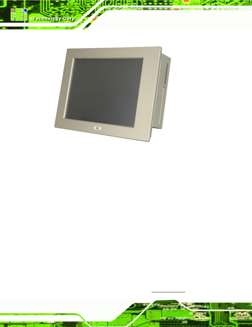
Figure 1-1: PPC-5xxx-9455
The PPC-5xxx-9455 flat panel PC is for industrial environments like production lines and machine automation. The PPC-5xxx-9455 provides all the features of a PC, combined with a touch panel screen for mouse and keyboard free data input. The PPC-5xxx-9455 provides wired and, optionally, wireless networking for integration into company networks. All major external device connections including USB, serial and parallel port connectors. Storage options include a 2.5” hard drive and a CompactFlash® slot, allowing for flexibility in choosing solid state drives or traditional hard drives. A VGA output on the rear panel allows the PPC-5xxx-9455 to connect to a second screen for duplicating the screen contents or extending the user interface.
1.1.1 PPC-5xxx-9455 Model Variations
Four IEI PPC-5xxx-9455 models are available. The models are listed in Table 1-1.
|
Model |
|
|
Socket / |
|
|
Power |
|
|
Screen |
|
|
Touch |
|
|
|
|
CPU |
|
|
|
|
|
|
Screen |
|
|||
|
|
|
|
|
|
|
|
|
|
|
|
|
||
|
|
|
|
|
|
|
|
|
|
|
|
|
|
|
|
PPC-5150A/9455-PIV651/4518AP/T-R/1 GB |
LGA775 |
|
AC input |
|
15” |
|
|
Yes |
|
||||
|
|
|
|
Intel® |
|
|
|
|
|
|
|
|
|
|
|
PPC-5150A/9455-PIV651/4520C/T-R/1 GB |
|
|
|
|
24 V DC input |
|
|
15” |
|
|
|
|
|
|
|
|
|
|
|
|
|
|
|
|
|
|||
|
|
|
|
|
|
|
|
|
|
|
|
|
|
|
Page 2
PPC-5xxx-9455 Panel PC
|
Model |
|
|
Socket / |
|
|
Power |
|
|
Screen |
|
|
Touch |
|
|
|
|
CPU |
|
|
|
|
|
|
Screen |
|
|||
|
|
|
|
|
|
|
|
|
|
|
|
|
||
|
|
|
|
|
|
|
|
|
|
|
|
|
|
|
|
PPC-5170A/9455-PIV651/4518AP/T-R/1 GB |
Pentium® 4 |
AC input |
|
17” |
|
|
|||||||
|
|
|
|
3.4 GHz |
|
|
|
|
|
|
|
|
|
|
|
PPC-5170A/9455-PIV651/4520C/T-R/1 GB |
|
|
|
24 V DC input |
|
|
17” |
|
|
|
|||
|
|
|
|
|
|
|
|
|
|
|||||
|
|
|
|
|
|
|
|
|
|
|
||||
|
PPC-5190A/9455-PIV651/4518AP/T-R/1 GB |
|
|
|
|
AC input |
|
19” |
|
|
||||
|
|
|
|
|
|
|
|
|
|
|
|
|||
|
PPC-5190A/9455-PIV651/4520C/T-R/1 GB |
|
|
|
|
|
24 V DC input |
|
19” |
|
|
|||
|
|
|
|
|
|
|
|
|
|
|
|
|
|
|
Table 1-1: PPC-5xxx-9455 Model Variation
1.1.2 Applications
The PPC-5xxx-9455 flat panel PC is designed for rigorous industrial environments where it may be exposed to both heat and moisture. Its durability and strength also makes it an ideal choice for public access computers. Some possible applications include:
Automated manufacturing processes
Public information gathering point
Plant environment monitoring system
Factory automation
Manufacturing shop flow
Equipment and device control
1.1.3 Features
Some of the features of the PPC-5xxx-9455 flat panel PC include:
Mainstream panel PC design with dual display function. Aluminum die-casting front panel meet IP 65 water proof standard
Support LGA755 Intel® Core™2 Duo, Pentium® D, Pentium® 4 and Celeron® D processors with 533/667/800/1066 MHz FSB
Dual DDR memory DIMM support up to 2 GB SDRAM SATA connectors
High brightness industrial grade LCD panel The following I/O ports
o 5 x COM (1 for Touch Screen) o 4 x USB 2.0 ports
Page 3
PPC-5xxx-9455 Panel PC
o 1 x PCI slot
o 1 x CompactFlash® slot o 1 x VGA port
o 1 x Parallel port
Dual 10/100/Gigabit Ethernet supported RoHS compliant
1.2 External Overview
The PPC-5xxx-9455 flat panel PC is comprised of an LCD screen, aluminum front panel and heavy duty steel rear and side panels. The rear panel provides screw holes for wall and an arm mounting. The right panel provides access to a slim type CD drive bay and a floppy disk drive bay. The bottom panel provides access to external interface connectors that include GbE, USB 2.0, audio, parallel port, serial port connectors, VGA port, PCI card slot and a CompactFlash® card slot.
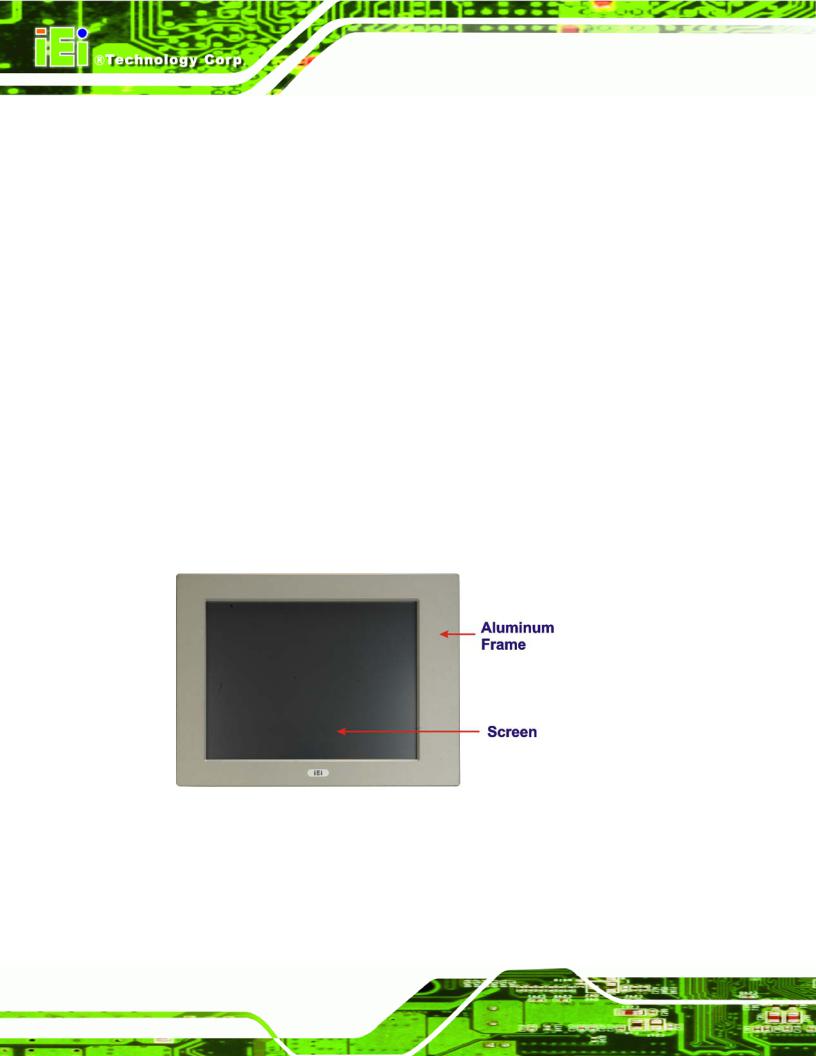
1.2.1 Front Panel
The front panel of the PPC-5xxx-9455 (Figure 1-2) is a flat panel TFT LCD screen surrounded by an aluminum frame.
Figure 1-2: Front View
Page 4
PPC-5xxx-9455 Panel PC
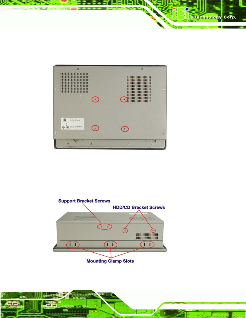
1.2.2 Rear Panel
The rear panel has a fan vent, four VESA standard mounting holes and several retention screw holes. The VESA mounting holes are circled in Figure 1-3.
Figure 1-3: PPC-5xxx-9455 Rear View
1.2.3 Top Panel
The top panel has two fan vents, eight mounting clamp slots and three retention screws for securing the drive bay bracket. The retention screws are circled in Figure 1-4 below.
Figure 1-4: PPC-5xxx-9455 Top View
Page 5
PPC-5xxx-9455 Panel PC
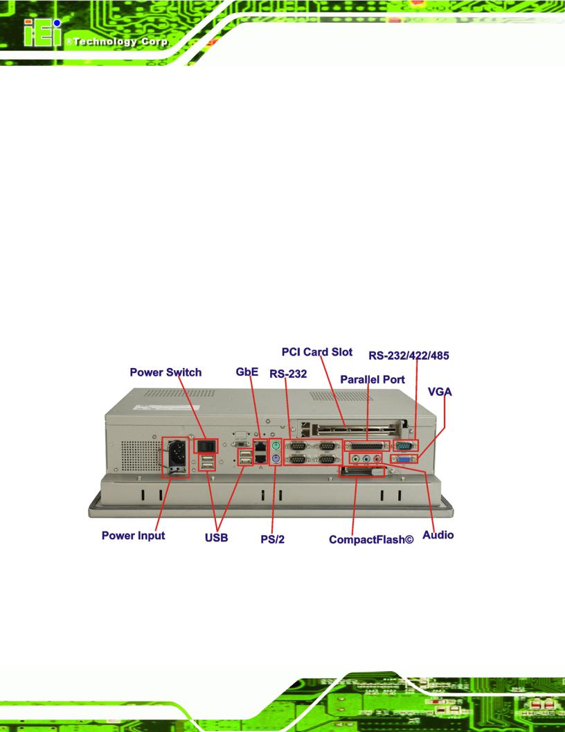
1.2.4 Bottom Panel
The bottom panel shown in Figure 1-5 has the following interfaces:
1 x Power input connector
1 x Power switch
4 x USB connectors
1 x Reset button
2 x RJ-45 GbE connectors
1 x PS/2 mouse connector
1 x PS/2 keyboard connector
5 x Serial port (COM) connectors
1 x PCI add-on card slot
1 x Parallel port connector
3 x Audio jacks
1 x VGA connector
1 x CompactFlash® slot
Figure 1-5: Bottom View
Page 6

PPC-5xxx-9455 Panel PC
1.2.5 Left Panel
The left side panel has two fan vents and four retention screws for securing the two internal fans. The retention screws are circled in Figure 1-6.
Figure 1-6: Left View
1.2.6 Right Panel
The right side panel provides access to a slim type CD drive bay and a FDD drive bay shown in Figure 1-7.
Figure 1-7: Right View
Page 7
PPC-5xxx-9455 Panel PC
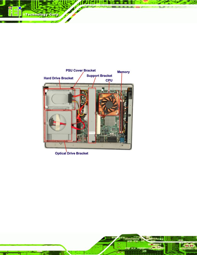
1.3 Internal Overview
The PPC-5xxx-9455 internal components are configured in three levels. The PSU cover bracket to the left (Figure 1-8) supports the hard drive and optical drive brackets. Below the PSU cover bracket is the power supply. On the same level as the power supply is the motherboard. Below the motherboard and PSU level is an LCD panel. An overview picture of the internal components is shown in Figure 1-8 below.
Figure 1-8: Internal Components
Page 8
PPC-5xxx-9455 Panel PC
Chapter
2
Specifications
Page 9

PPC-5xxx-9455 Panel PC
2.1 Introduction
The PPC-5xxx-9455 flat panel PC has the following preinstalled components:
1 x Motherboard
1 x TFT LCD screen
1 x Power supply
2 x Cooling fans
The technical specifications for these components and the system are shown in the sections below.
2.1.1 System Specifications
The technical specifications for the PPC-5xxx-9455 system are listed in Table 2-1.
SPECIFICATION |
DESCRIPTION |
|
|
Front Panel |
Aluminum Front Panel meets IP 65 standard |
|
|
Chassis |
Heavy-duty Steel |
|
|
LCD Panel |
High luminance TFT LCD |
|
|
Resolution |
PPC-5150A-9455: 1024 x 768 (XGA) |
|
PPC-5170A-9455: 1280 x 1024 (SXGA) |
|
PPC-5190A-9455: 1280 x 1024 (SXGA) |
|
|
Brightness |
PPC-5150A-9455: 350 cd/m2 |
|
PPC-5170A-9455: 300 cd/m2 |
|
PPC-5190A-9455: 300 cd/m2 |
|
|
Contrast Ratio |
PPC-5150A-9455: 700:1 |
|
PPC-5170A-9455: 800:1 |
|
PPC-5190A-9455: 800:1 |
|
|
LCD MTBF |
50,000 hrs |
|
|
Backlight MTBF |
50,000 hrs |
|
|
Viewing Angle (H/V) |
PPC-5150A-9455: 140/125 |
|
PPC-5170A-9455: 160/160 |
|
PPC-5190A-9455: 160/160 |
|
|
Page 10
PPC-5xxx-9455 Panel PC
SPECIFICATION |
DESCRIPTION |
|
|
Touch Screen |
Optional 5-wire resistive type touch screen with |
|
RS-232 interface |
|
|
Display |
Supports Dual Display |
|
|
Add-On Card (Optional) |
One PCI card |
|
|
Drive Bay |
One 2.5” HDD bay with anti-shock |
|
One slim type CD drive bay |
|
One slim type FDD bay |
|
One CompactFlash® slot |
|
|
Power Supply |
Input voltage: 90~265 V AC, 50~60 Hz |
|
Output rating: 180 W |
|
Output voltage: |
|
+3.3 V @ 16.8A |
|
+5 V @ 12A |
|
+12 V @ 10A |
|
-12 V @ 0.8A |
|
+5 VSB @ 2A |
|
|
|
Input voltage: 24 VDC (18-36 VDC) |
|
Output rating: 200 W |
|
Output voltage: |
|
+3.3 V @ 12A |
|
+5 V @ 12A |
|
+12 V @ 15.4A |
|
-12 V @ 0.5A |
|
+5 VSB @ 2A |
|
|
Mounting Feature |
Panel, Arm, Wall, or Rack/Cabinet |
|
|
Color |
Silver (PANTONE PMS-8001) |
|
|
Operating Temperature |
0~50˚C |
|
|
Relative Humidity |
5 ~ 85%, non-condensing |
|
|
Vibration |
5 - 17Hz, 0.1” double amplitude displacement |
|
17 - 640Hz, 1.5G acceleration, peak to peak |
|
|
Page 11

|
PPC-5xxx-9455 Panel PC |
|
|
|
|
SPECIFICATION |
DESCRIPTION |
|
|
|
|
Shock |
10G Acceleration, peak to peak (11ms) |
|
|
|
|
Dimensions (W x D x H) |
PPC-5150A-9455: 410 mm x 309 mm x 110.5 mm |
|
|
PPC-5170A-9455: 452 mm x 356 mm x 115 mm |
|
|
PPC-5190A-9455: 483 mm x 399 mm x 115.2 mm |
|
|
|
|
Net/Gross Weight |
PPC-5150A-9455: 7 kg/11 kg |
|
|
PPC-5170A-9455: 8 kg/12 kg |
|
|
PPC-5190A-9455: 12.6 kg/18.2 kg |
|
|
|
|
Environment |
RoHS Compliant |
|
|
|
|
Table 2-1: PPC-5xxx-9455 Specifications
2.1.2 Motherboard Specifications
The PPC-5xxx-9455 comes with a POS-9455 motherboard. The technical specifications of the motherboard are listed in Table 2-2.
SPECIFICATION |
DESCRIPTION |
|
|
CPU |
LGA775 |
|
Intel® Core™2 Duo |
|
Pentium® 4 |
|
Pentium® D |
|
Celeron® D |
|
|
Northbridge |
Intel® 945G |
|
|
Southbridge |
Intel® ICH7 |
|
|
Max. FSB |
533 MHz |
|
|
Memory |
2 x 2.0 GB (max) 400/533/667 MHz DDR2 DIMM sockets |
|
up to 4.0 GB (total) |
|
|
BIOS |
AMI BIOS Label |
|
|
Display |
CRT integrated in Intel® 945G |
|
LVDS Dual 18/24-bit TTL LCD implemented through a |
|
Chrontel CH7308B LVDS chipset |
|
|
Page 12
 Loading...