


 Loading...
KINO-DH610 CPU Card
IEI Technology Corp.
MODEL:
KINO-DH610
Mini-ITX SBC Supports LGA1155 for Intel® Core™ i3/ Pentium®/ Celeron® CPU, DDR3, VGA/DVI-D/HDMI, Dual PCIe GbE, Ten USB 2.0, Four SATA 3Gb/s, HD Audio and RoHS
User Manual
Rev. 1.00 - 30 December, 2011
KINO-DH610
Revision
Date |
Version |
Changes |
|
|
|
30 December, 2011 |
1.00 |
Initial release |
|
|
|
Page II
KINO-DH610
Copyright
COPYRIGHT NOTICE
The information in this document is subject to change without prior notice in order to improve reliability, design and function and does not represent a commitment on the part of the manufacturer.
In no event will the manufacturer be liable for direct, indirect, special, incidental, or consequential damages arising out of the use or inability to use the product or documentation, even if advised of the possibility of such damages.
This document contains proprietary information protected by copyright. All rights are reserved. No part of this manual may be reproduced by any mechanical, electronic, or other means in any form without prior written permission of the manufacturer.
TRADEMARKS
All registered trademarks and product names mentioned herein are used for identification purposes only and may be trademarks and/or registered trademarks of their respective owners.
Page III
KINO-DH610
Table of Contents |
|
1 INTRODUCTION.......................................................................................................... |
1 |
1.1 INTRODUCTION........................................................................................................... |
2 |
1.2 CONNECTORS ............................................................................................................. |
2 |
1.3 DIMENSIONS............................................................................................................... |
4 |
1.4 DATA FLOW ................................................................................................................ |
5 |
1.5 TECHNICAL SPECIFICATIONS ...................................................................................... |
6 |
2 UNPACKING ................................................................................................................. |
9 |
2.1 ANTI-STATIC PRECAUTIONS ...................................................................................... |
10 |
2.2 UNPACKING PRECAUTIONS....................................................................................... |
10 |
2.3 PACKING LIST............................................................................................................ |
11 |
2.4 OPTIONAL ITEMS...................................................................................................... |
12 |
3 CONNECTORS ........................................................................................................... |
14 |
3.1 PERIPHERAL INTERFACE CONNECTORS..................................................................... |
15 |
3.1.1 KINO-DH610 Layout....................................................................................... |
15 |
3.1.2 Peripheral Interface Connectors ..................................................................... |
16 |
3.1.3 External Interface Panel Connectors............................................................... |
17 |
3.2 INTERNAL PERIPHERAL CONNECTORS ...................................................................... |
17 |
3.2.1 Battery Connector............................................................................................ |
17 |
3.2.2 BIOS Update Connector .................................................................................. |
18 |
3.2.3 DDR3 SO-DIMM Slots .................................................................................... |
19 |
3.2.4 Debug Port Connector..................................................................................... |
20 |
3.2.5 Digital I/O Connector ...................................................................................... |
21 |
3.2.6 EC Update Connector...................................................................................... |
22 |
3.2.7 Fan Connector (CPU)...................................................................................... |
23 |
3.2.8 Fan Connector (PCH)...................................................................................... |
24 |
3.2.9 Front Panel Connector .................................................................................... |
24 |
3.2.10 Keyboard/Mouse Connector .......................................................................... |
25 |
3.2.11 PCI Slot .......................................................................................................... |
26 |
3.2.12 PCIe x1 Slot ................................................................................................... |
27 |
Page IV
KINO-DH610 |
|
3.2.13 Power Connector ........................................................................................... |
28 |
3.2.14 SATA Drive Connectors ................................................................................. |
28 |
3.2.15 SATA Power Connectors ................................................................................ |
29 |
3.2.16 Serial Port Connector (RS-232/422/485) ...................................................... |
30 |
3.2.17 TPM Connector.............................................................................................. |
31 |
3.2.18 USB Connectors............................................................................................. |
32 |
3.3 EXTERNAL PERIPHERAL INTERFACE CONNECTOR PANEL ......................................... |
33 |
3.3.1 Audio Connector .............................................................................................. |
34 |
3.3.2 Ethernet and USB Connector........................................................................... |
34 |
3.3.3 HDMI Connector ............................................................................................. |
35 |
3.3.4 Power Connector ............................................................................................. |
36 |
3.3.5 RS-232 Serial Port ........................................................................................... |
37 |
3.3.6 VGA and DVI Connector ................................................................................. |
38 |
4 INSTALLATION ......................................................................................................... |
39 |
4.1 ANTI-STATIC PRECAUTIONS ...................................................................................... |
40 |
4.2 INSTALLATION CONSIDERATIONS.............................................................................. |
41 |
4.3 BASIC INSTALLATION ............................................................................................... |
42 |
4.3.1 Socket LGA1155 CPU Installation .................................................................. |
42 |
4.3.2 Cooling Kit Installation ................................................................................... |
45 |
4.3.3 DIMM Installation ........................................................................................... |
47 |
4.4 JUMPER SETTINGS .................................................................................................... |
48 |
4.4.1 AT/ATX Mode Select Jumper ........................................................................... |
48 |
4.4.2 Clear CMOS Jumper........................................................................................ |
49 |
4.5 INTERNAL PERIPHERAL DEVICE CONNECTIONS........................................................ |
50 |
4.5.1 SATA Drive Connection ................................................................................... |
51 |
4.6 EXTERNAL PERIPHERAL INTERFACE CONNECTION ................................................... |
52 |
4.6.1 Audio Connection............................................................................................. |
53 |
4.6.2 DVI Display Device Connection...................................................................... |
53 |
4.6.3 HDMI Display Device Connection .................................................................. |
54 |
4.6.4 LAN Connection............................................................................................... |
55 |
4.6.5 Serial Device Connection ................................................................................ |
56 |
4.6.6 USB Connection............................................................................................... |
57 |
4.6.7 VGA Monitor Connection ................................................................................ |
58 |
5 BIOS SCREENS........................................................................................................... |
60 |
|
Page V |

|
KINO-DH610 |
5.1 INTRODUCTION......................................................................................................... |
61 |
5.1.1 Starting Setup................................................................................................... |
61 |
5.1.2 Using Setup ...................................................................................................... |
61 |
5.1.3 Getting Help..................................................................................................... |
62 |
5.1.4 Unable to Reboot after Configuration Changes .............................................. |
62 |
5.1.5 BIOS Menu Bar................................................................................................ |
62 |
5.2 MAIN........................................................................................................................ |
63 |
5.3 ADVANCED ............................................................................................................... |
64 |
5.3.1 ACPI Configuration ......................................................................................... |
65 |
5.3.2 Trusted Computing........................................................................................... |
66 |
5.3.3 CPU Configuration.......................................................................................... |
67 |
5.3.3.1 CPU Information....................................................................................... |
68 |
5.3.4 SATA Configuration ......................................................................................... |
69 |
5.3.5 USB Configuration........................................................................................... |
71 |
5.3.6 Super IO Configuration ................................................................................... |
72 |
5.3.6.1 Serial Port n Configuration ....................................................................... |
73 |
5.3.7 H/W Monitor .................................................................................................... |
76 |
5.3.7.1 CPU Fan Configuration ............................................................................ |
77 |
5.3.7.2 SYS Fan 1 Configuration.......................................................................... |
78 |
5.3.8 Serial Port Console Redirection ...................................................................... |
80 |
5.3.9 IEI Feature....................................................................................................... |
81 |
5.4 CHIPSET ................................................................................................................... |
82 |
5.4.1 Northbridge Configuration .............................................................................. |
83 |
5.4.2 Southbridge Configuration .............................................................................. |
85 |
5.4.3 Integrated Graphics ......................................................................................... |
87 |
5.4.4 ME Subsystem .................................................................................................. |
88 |
5.5 BOOT........................................................................................................................ |
89 |
5.6 SECURITY................................................................................................................. |
91 |
5.7 SAVE & EXIT ............................................................................................................ |
92 |
6 SOFTWARE DRIVERS .............................................................................................. |
94 |
6.1 AVAILABLE SOFTWARE DRIVERS .............................................................................. |
95 |
6.2 SOFTWARE INSTALLATION ........................................................................................ |
95 |
6.3 CHIPSET DRIVER INSTALLATION............................................................................... |
97 |
6.4 GRAPHICS DRIVER INSTALLATION.......................................................................... |
100 |
Page VI

KINO-DH610 |
|
6.5 LAN DRIVER INSTALLATION.................................................................................. |
103 |
6.6 AUDIO DRIVER INSTALLATION ............................................................................... |
105 |
A BIOS MENU OPTIONS ........................................................................................... |
108 |
B ONE KEY RECOVERY............................................................................................ |
111 |
B.1 ONE KEY RECOVERY INTRODUCTION ..................................................................... |
112 |
B.1.1 System Requirement........................................................................................ |
113 |
B.1.2 Supported Operating System .......................................................................... |
114 |
B.2 SETUP PROCEDURE FOR WINDOWS......................................................................... |
115 |
B.2.1 Hardware and BIOS Setup ............................................................................. |
115 |
B.2.2 Create Partitions ............................................................................................ |
116 |
B.2.3 Install Operating System, Drivers and Applications..................................... |
120 |
B.2.4 Build-up Recovery Partition.......................................................................... |
120 |
B.2.5 Create Factory Default Image....................................................................... |
123 |
B.3 SETUP PROCEDURE FOR LINUX .............................................................................. |
128 |
B.4 RECOVERY TOOL FUNCTIONS ................................................................................ |
131 |
B.4.1 Factory Restore ............................................................................................. |
133 |
B.4.2 Backup System ............................................................................................... |
134 |
B.4.3 Restore Your Last Backup.............................................................................. |
135 |
B.4.4 Manual........................................................................................................... |
136 |
B.5 OTHER INFORMATION ............................................................................................ |
136 |
B.5.1 Using AHCI Mode or ALi M5283 / VIA VT6421A Controller....................... |
136 |
B.5.2 System Memory Requirement ........................................................................ |
138 |
C TERMINOLOGY ..................................................................................................... |
139 |
D WATCHDOG TIMER .............................................................................................. |
144 |
E HAZARDOUS MATERIALS DISCLOSURE ....................................................... |
147 |
E.1 HAZARDOUS MATERIAL DISCLOSURE TABLE FOR IPB PRODUCTS CERTIFIED AS |
|
ROHS COMPLIANT UNDER 2002/95/EC WITHOUT MERCURY ..................................... |
148 |
Page VII

KINO-DH610
List of Figures |
|
Figure 1-1: KINO-DH610................................................................................................................. |
2 |
Figure 1-2: Connectors .................................................................................................................. |
3 |
Figure 1-3: KINO-DH610 Dimensions (mm) ................................................................................. |
4 |
Figure 1-4: Data Flow Diagram...................................................................................................... |
5 |
Figure 3-1: Connector and Jumper Locations........................................................................... |
15 |
Figure 3-2: Battery Connector Location..................................................................................... |
18 |
Figure 3-3: BIOS Update Connector Location ........................................................................... |
19 |
Figure 3-4: DDR3 SO-DIMM Slot Locations ............................................................................... |
20 |
Figure 3-5: Debug Port Connector Location.............................................................................. |
20 |
Figure 3-6: Digital I/O Connector Location ................................................................................ |
21 |
Figure 3-7: EC Update Connector Location............................................................................... |
22 |
Figure 3-8: CPU Fan Connector Locations ................................................................................ |
23 |
Figure 3-9: PCH Fan Connector Location .................................................................................. |
24 |
Figure 3-10: Front Panel Connector Location ........................................................................... |
25 |
Figure 3-11: Keyboard/Mouse Connector Location.................................................................. |
26 |
Figure 3-12: PCI Slot Location .................................................................................................... |
27 |
Figure 3-13: PCIe x1 Slot Location ............................................................................................. |
27 |
Figure 3-14: Power Connector Location .................................................................................... |
28 |
Figure 3-15: SATA Drive Connector Locations ......................................................................... |
29 |
Figure 3-16: SATA Power Connector Locations ....................................................................... |
29 |
Figure 3-17: RS-232/422/485 Serial Port Connector Location RS-232+RS422/485 .......... |
30 |
Figure 3-18: TPM Connector Location........................................................................................ |
31 |
Figure 3-19: USB Connector Locations...................................................................................... |
32 |
Figure 3-20: KINO-DH610 External Peripheral Interface Connector........................................ |
33 |
Figure 3-21: Audio Connector ..................................................................................................... |
34 |
Figure 3-22: LAN Connector........................................................................................................ |
35 |
Figure 3-23: Power Connector .................................................................................................... |
36 |
Figure 3-24: RS-232 Serial Port Connector................................................................................ |
37 |
Figure 3-25: VGA Connector ....................................................................................................... |
38 |
Figure 4-1: Disengage the CPU Socket Load Lever.................................................................. |
43 |
Figure 4-2: Remove Protective Cover......................................................................................... |
43 |
Page VIII

KINO-DH610 |
|
Figure 4-3: Insert the Socket LGA1155 CPU.............................................................................. |
44 |
Figure 4-4: Close the Socket LGA1155 ...................................................................................... |
45 |
Figure 4-5: Cooling Kits (CF-1156A-RS, CF-1156B-RS, CF-1156C-RS, CF-1156D-RS).......... |
45 |
Figure 4-6: Cooling Kit Support Bracket.................................................................................... |
46 |
Figure 4-7: DIMM Installation....................................................................................................... |
47 |
Figure 4-8: Jumper Locations ..................................................................................................... |
48 |
Figure 4-9: AT/ATX Mode Select Jumper Location................................................................... |
49 |
Figure 4-10: Clear CMOS Jumper Location ............................................................................... |
50 |
Figure 4-11: SATA Drive Cable Connection............................................................................... |
51 |
Figure 4-12: SATA Power Drive Connection.............................................................................. |
52 |
Figure 4-13: Audio Connector ..................................................................................................... |
53 |
Figure 4-14: DVI Connector ......................................................................................................... |
54 |
Figure 4-15: LAN Connection ...................................................................................................... |
56 |
Figure 4-16: Serial Device Connector......................................................................................... |
57 |
Figure 4-17: USB Connector........................................................................................................ |
58 |
Figure 4-18: VGA Connector ....................................................................................................... |
59 |
Figure 6-1: Introduction Screen .................................................................................................. |
96 |
Figure 6-2: Available Drivers ....................................................................................................... |
96 |
Figure 6-3: Chipset Driver Screen............................................................................................... |
97 |
Figure 6-4: Chipset Driver Welcome Screen.............................................................................. |
98 |
Figure 6-5: Chipset Driver License Agreement ......................................................................... |
98 |
Figure 6-6: Chipset Driver Read Me File .................................................................................... |
99 |
Figure 6-7: Chipset Driver Setup Operations ............................................................................ |
99 |
Figure 6-8: Chipset Driver Installation Finish Screen............................................................ |
100 |
Figure 6-9: Graphics Driver Welcome Screen ........................................................................ |
101 |
Figure 6-10: Graphics Driver License Agreement.................................................................. |
101 |
Figure 6-11: Graphics Driver Setup Operations ..................................................................... |
102 |
Figure 6-12: Graphics Driver Installation Finish Screen ....................................................... |
102 |
Figure 6-13: LAN Driver Welcome Screen .............................................................................. |
103 |
Figure 6-14: LAN Driver Ready to Install Screen.................................................................... |
104 |
Figure 6-15: LAN Driver Setup Status Screen ........................................................................ |
104 |
Figure 6-16: LAN Driver Installation Complete....................................................................... |
105 |
Figure 6-17: Audio Driver – Extracting Files........................................................................... |
106 |
Figure 6-18: Audio Driver Welcome Screen............................................................................ |
106 |
Figure 6-19: Audio Driver Installation...................................................................................... |
106 |
Page IX

|
KINO-DH610 |
Figure 6-20: Audio Driver Installation Complete .................................................................... |
107 |
Figure B-1: IEI One Key Recovery Tool Menu ........................................................................ |
112 |
Figure B-2: Launching the Recovery Tool .............................................................................. |
117 |
Figure B-3: Recovery Tool Setup Menu .................................................................................. |
117 |
Figure B-4: Command Mode..................................................................................................... |
117 |
Figure B-5: Partition Creation Commands.............................................................................. |
119 |
Figure B-6: Launching the Recovery Tool .............................................................................. |
121 |
Figure B-7: System Configuration for Windows .................................................................... |
121 |
Figure B-8: Build-up Recovery Partition ................................................................................. |
122 |
Figure B-9: Press any key to continue .................................................................................... |
122 |
Figure B-10: Press F3 to Boot into Recovery Mode............................................................... |
123 |
Figure B-11: Recovery Tool Menu ........................................................................................... |
123 |
Figure B-12: About Symantec Ghost Window........................................................................ |
124 |
Figure B-13: Symantec Ghost Path ......................................................................................... |
124 |
Figure B-14: Select a Local Source Drive ............................................................................... |
125 |
Figure B-15: Select a Source Partition from Basic Drive ...................................................... |
125 |
Figure B-16: File Name to Copy Image to ............................................................................... |
126 |
Figure B-17: Compress Image.................................................................................................. |
126 |
Figure B-18: Image Creation Confirmation ............................................................................. |
127 |
Figure B-19: Image Creation Complete ................................................................................... |
127 |
Figure B-20: Image Creation Complete ................................................................................... |
127 |
Figure B-21: Press Any Key to Continue ................................................................................ |
128 |
Figure B-22: Partitions for Linux.............................................................................................. |
129 |
Figure B-23: System Configuration for Linux......................................................................... |
130 |
Figure B-24: Access menu.lst in Linux (Text Mode).............................................................. |
130 |
Figure B-25: Recovery Tool Menu ........................................................................................... |
131 |
Figure B-26: Recovery Tool Main Menu .................................................................................. |
132 |
Figure B-27: Restore Factory Default...................................................................................... |
133 |
Figure B-28: Recovery Complete Window .............................................................................. |
133 |
Figure B-29: Backup System.................................................................................................... |
134 |
Figure B-30: System Backup Complete Window ................................................................... |
134 |
Figure B-31: Restore Backup ................................................................................................... |
135 |
Figure B-32: Restore System Backup Complete Window..................................................... |
135 |
Figure B-33: Symantec Ghost Window ................................................................................... |
136 |
Page X
KINO-DH610
List of Tables |
|
Table 1-1: Technical Specifications.............................................................................................. |
8 |
Table 3-1: Peripheral Interface Connectors ............................................................................... |
16 |
Table 3-2: Rear Panel Connectors .............................................................................................. |
17 |
Table 3-3: Battery Connector Pinouts ........................................................................................ |
18 |
Table 3-4: BIOS Update Connector Pinouts .............................................................................. |
19 |
Table 3-5: Debug Port Connector Pinouts ................................................................................. |
21 |
Table 3-6: Digital I/O Connector Pinouts.................................................................................... |
22 |
Table 3-7: EC Update Connector Pinouts .................................................................................. |
23 |
Table 3-8: CPU Fan Connector Pinouts...................................................................................... |
23 |
Table 3-9: PCH Fan Connector Pinouts...................................................................................... |
24 |
Table 3-10: Front Panel Connector Pinouts............................................................................... |
25 |
Table 3-11: Keyboard/Mouse Connector Pinouts ..................................................................... |
26 |
Table 3-12: Power Connector Pinouts........................................................................................ |
28 |
Table 3-13: SATA Power Connector Pinouts............................................................................. |
30 |
Table 3-14: RS-232/422/485 Serial Port Connector Pinouts RS-232+RS422/485 ............. |
31 |
Table 3-15: TPM Connector Pinouts........................................................................................... |
32 |
Table 3-16: USB Connector Pinouts........................................................................................... |
33 |
Table 3-17: LAN and USB Connector Pinouts ........................................................................... |
35 |
Table 3-18: HDMI Connector Pinouts ......................................................................................... |
36 |
Table 3-19: Power Connector Pinouts........................................................................................ |
37 |
Table 3-20: RS-232 Serial Port Connector Pinouts ................................................................... |
37 |
Table 3-21: DVI and VGA Connector Pinouts ............................................................................ |
38 |
Table 4-1: Jumpers....................................................................................................................... |
48 |
Table 4-2: AT/ATX Mode Select Jumper Settings ..................................................................... |
49 |
Table 4-3: Clear CMOS Jumper Settings.................................................................................... |
50 |
Table 5-1: BIOS Navigation Keys ................................................................................................ |
62 |
Page XI

KINO-DH610
List of BIOS Menus |
|
BIOS Menu 1: Main ....................................................................................................................... |
63 |
BIOS Menu 2: Advanced .............................................................................................................. |
65 |
BIOS Menu 3: ACPI Configuration.............................................................................................. |
65 |
BIOS Menu 4: TPM Configuration............................................................................................... |
66 |
BIOS Menu 5: CPU Configuration............................................................................................... |
67 |
BIOS Menu 6: CPU Configuration............................................................................................... |
68 |
BIOS Menu 7: IDE Configuration................................................................................................. |
69 |
BIOS Menu 9: USB Configuration............................................................................................... |
71 |
BIOS Menu 10: Super IO Configuration...................................................................................... |
72 |
BIOS Menu 11: Serial Port n Configuration Menu..................................................................... |
73 |
BIOS Menu 12: Hardware Health Configuration ........................................................................ |
76 |
BIOS Menu 13: CPU Fan Configuration...................................................................................... |
77 |
BIOS Menu 14: SYS Fan 1 Configuration................................................................................... |
79 |
BIOS Menu 15: Serial Port Console Redirection Menu............................................................. |
80 |
BIOS Menu 16: IEI Feature........................................................................................................... |
81 |
BIOS Menu 17: Chipset ................................................................................................................ |
82 |
BIOS Menu 18: Northbridge Chipset Configuration.................................................................. |
83 |
BIOS Menu 19: Southbridge Chipset Configuration ................................................................. |
86 |
BIOS Menu 20: Integrated Graphics ........................................................................................... |
87 |
BIOS Menu 21: ME Subsystem.................................................................................................... |
88 |
BIOS Menu 22: Boot ..................................................................................................................... |
89 |
BIOS Menu 23: Security ............................................................................................................... |
91 |
BIOS Menu 24:Exit........................................................................................................................ |
92 |
Page XII
KINO-DH610
Chapter
1
1 Introduction
Page 1
KINO-DH610
1.1 Introduction
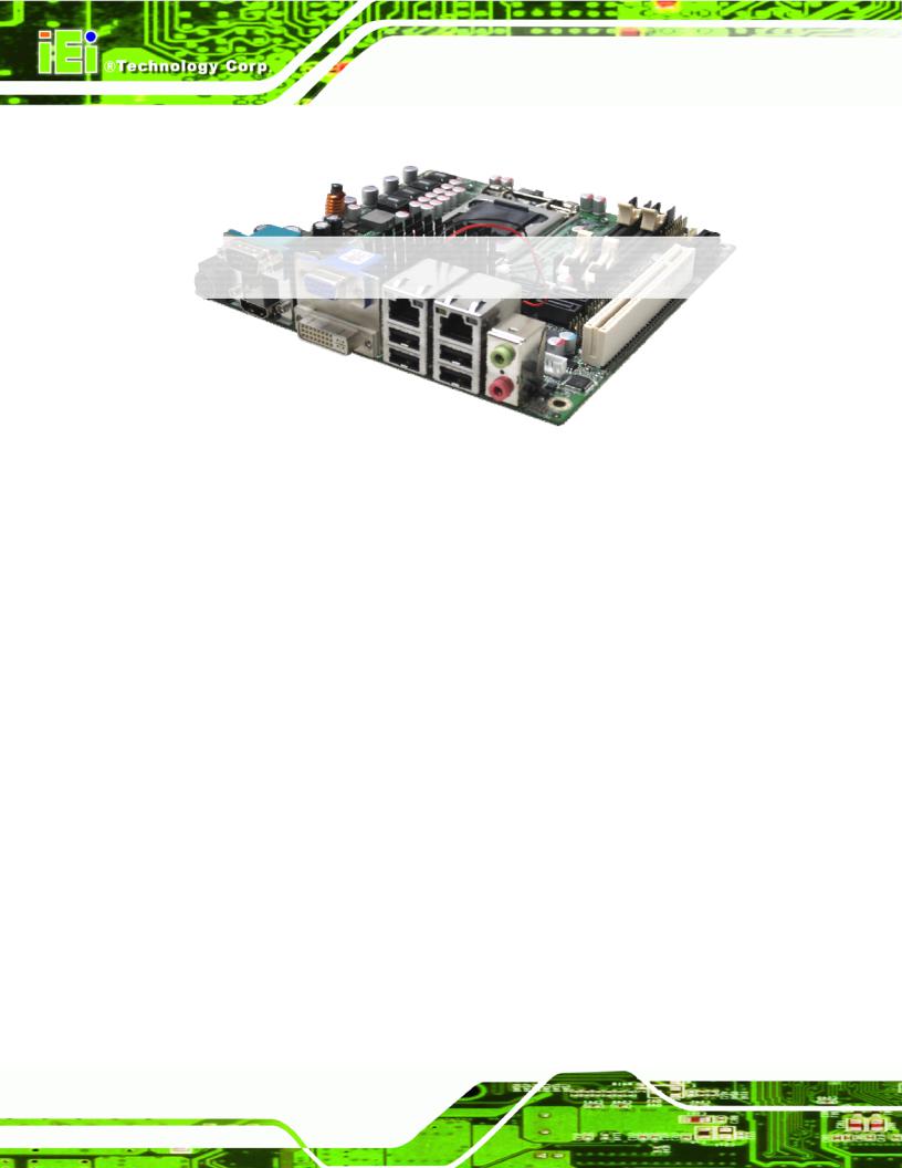
Figure 1-1: KINO-DH610
The KINO-DH610 is a Mini-ITX motherboard. It accepts a LGA1155 Intel® Core™ i3/ Pentium®/Celeron® processor and supports two 204-pin 1333/1066 MHz dual-channel DDR3 SO-DIMM modules up to 16 GB.
The integrated Intel® H61 System Chipset supports two GbE LAN ports through dual Realtek RTL8111E PCIe GbE controllers (with ASF 2.0 support). The KINO-DH610 also supports four SATA 3Gb/s drives and provides 5 V SATA power.
The KINO-DH610 includes a VGA, DVI-D and HDMI port. Expansion and I/O include one PCI slot, one PCIe x1 slot, four USB 2.0 ports on the rear panel and six USB 2.0 ports by pin header. Serial device connectivity is provided by one external RS-232 and one internal RS-232/422/485 connectors.
1.2 Connectors
The connectors on the KINO-DH610 are shown in the figure below.
Page 2

KINO-DH610
Figure 1-2: Connectors
Page 3

KINO-DH610
1.3 Dimensions
The dimensions of the board are listed below:
|
Length: |
170 mm |
|
Width: |
170 mm |
Figure 1-3: KINO-DH610 Dimensions (mm)
Page 4

KINO-DH610
1.4 Data Flow
Figure 1-4 shows the data flow between the system chipset, the CPU and other components installed on the motherboard.
Figure 1-4: Data Flow Diagram
Page 5

KINO-DH610
1.5 Technical Specifications
KINO-DH610 technical specifications are listed in table below.
Specification |
KINO-DH610 |
|
|
Form Factor |
Mini-ITX |
|
|
Socket |
LGA1155 |
|
|
CPU Supported |
Socket 1155 Intel® Core™ i3/ Pentium®/ Celeron® dual core |
|
processor |
|
|
System Chipset |
Intel® H61 |
|
|
Memory |
Two 204-pin 1066/1333 MHz dual-channel DDR3 SO-DIMM |
|
supported (system max. 16 GB) |
|
|
Graphics Engine |
Support for DX10.1 and OpenGL3.0, full MPEG2. VC1. AVC |
|
decode |
|
|
Audio |
Realtek ALC662 HD Audio codec |
|
|
LAN |
Two Realtek RTL8111E PCIe GbE controllers with ASF 2.0 |
|
support |
|
|
Embedded Controller |
iWDD |
|
|
Super I/O |
Fintek F81866 |
|
|
Digital I/O |
8-bit digital I/O, 4-bit input/4-bit output |
|
|
BIOS |
UEFI BIOS |
|
|
Watchdog Timer |
Software programmable supports 1~255 sec. system reset |
|
|
Expansions |
|
|
|
PCIe |
One PCIe x1 slot |
|
|
PCI |
One PCI slot |
|
|
I/O Interface Connectors |
|
|
|
Audio Connector |
Two external audio jacks (Line-out, Mic) |
|
|
Page 6

KINO-DH610
Specification |
KINO-DH610 |
|
|
Display Ports |
One VGA integrated in Intel® H61 |
|
One DVI-D integrated in Intel® H61 |
|
One HDMI integrated in Intel® H61 |
|
|
Ethernet |
Two RJ-45 GbE ports |
|
|
Keyboard/Mouse |
One internal keyboard and mouse connector via 6-pin wafer |
|
|
TPM |
One 20-pin header |
|
|
Fan |
One 4-pin CPU fan connector |
|
One 3-pin system fan connector |
|
|
Serial Ports |
One external RS-232 serial port via DB-9 male connector |
|
One RS-232 and one RS-422/485 via internal 14-pin header |
|
|
USB Ports |
Four external USB 2.0 ports by rear IO |
|
Six internal USB 2.0 ports via three 8-pin headers |
|
|
Storage |
|
|
|
Serial ATA |
Four SATA 3Gb/s connectors |
|
|
Environmental and Power Specifications |
|
|
|
Power Supply |
Maximum input voltage range: 9 V ~ 28 V |
|
Recommended operating input voltage range: 12 V ~ 24 V |
|
|
Power Connector |
One external DC jack (4-pin DIN) |
|
One internal 4-pin power connector |
|
|
Power Consumption |
12V@5.07A (2.2 GHz Intel® G620T with two 1066 MHz 2 GB |
|
DDR3 running 3DMark06 burn in) |
|
12V@8.85A (2.8 GHz Intel® Core™ i7-2600S with two 1066 |
|
MHz 2 GB DDR3 running 3DMark06 burn in) |
|
|
Operating Temperature |
-10ºC ~ 60ºC |
|
|
Humidity |
5% ~ 95% (non-condensing) |
|
|
Physical Specifications |
|
|
|
Dimensions |
170 mm x 170 mm |
|
|
Page 7

KINO-DH610
Specification |
KINO-DH610 |
|
|
Weight GW/NW |
1100 g / 700 g |
|
|
Table 1-1: Technical Specifications
Page 8
KINO-DH610
Chapter
2
2 Unpacking
Page 9
KINO-DH610
2.1 Anti-static Precautions
 WARNING!
Static electricity can destroy certain electronics. Make sure to follow the ESD precautions to prevent damage to the product, and injury to the user.
Make sure to adhere to the following guidelines:
Wear an anti-static wristband: Wearing an anti-static wristband can prevent electrostatic discharge.
Self-grounding: Touch a grounded conductor every few minutes to discharge any excess static buildup.
Use an anti-static pad: When configuring any circuit board, place it on an anti-static mat.
Only handle the edges of the PCB: Don't touch the surface of the motherboard. Hold the motherboard by the edges when handling.
2.2Unpacking Precautions
When the KINO-DH610 is unpacked, please do the following:
Follow the antistatic guidelines above.
Make sure the packing box is facing upwards when opening.
Make sure all the packing list items are present.
Page 10
KINO-DH610
2.3 Packing List
 NOTE:
NOTE:
If any of the components listed in the checklist below are missing, do not proceed with the installation. Contact the IEI reseller or vendor the KINO-DH610 was purchased from or contact an IEI sales representative directly by sending an email to sales@iei.com.tw.
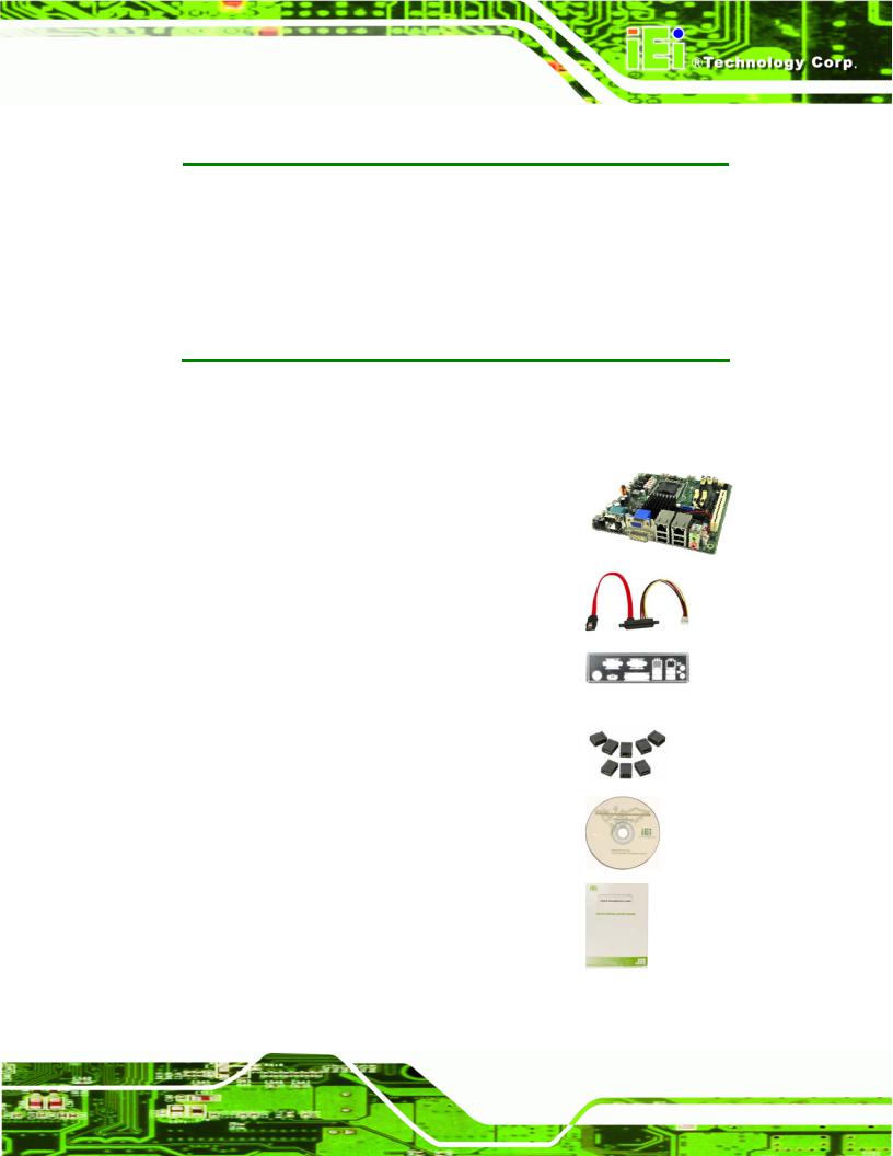
The KINO-DH610 is shipped with the following components:
Quantity |
Item and Part Number |
Image |
|
|
|
1 |
KINO-DH610 motherboard |
|
|
|
|
2 |
SATA with 5V power cable |
|
|
(P/N: 32801-000201-100-RS) |
|
|
|
|
1 |
I/O shielding |
|
|
(P/N: 45014-0032C0-00-RS) |
|
|
|
|
1 |
Mini jumper pack (2.0mm) |
|
|
|
|
1 |
Utility CD |
|
|
|
|
1 |
Quick Installation Guide |
|
|
|
|
Page 11
KINO-DH610
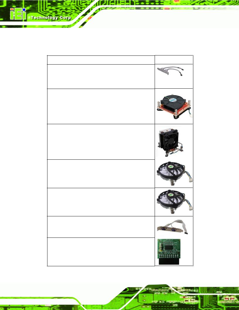
2.4 Optional Items
The following are optional components which may be separately purchased:
Item and Part Number |
Image |
Dual-port USB cable with bracket (P/N: 19800-003100-100-RS)
High-performance LGA1155/LGA1156 cooler kit, 1U chassis compatible, 73W
(P/N: CF-1156A-RS)
High-performance LGA1155/LGA1156 cooler kit, 95W (P/N: CF-1156B-RS)
LGA1155/LGA1156 cooler kit, 1U Chassis compatible, 45W
(P/N: CF-1156C-RS)
LGA1155/LGA1156 cooler kit, 1U Chassis compatible, 65W
(P/N: CF-1156D-RS)
RS-232/422/485 cable with bracket (P/N: 19800-004300-100-RS)
20-pin Infineon TPM module, software management tool, firmware V3.17
(P/N: TPM-IN01-R11)
Page 12
KINO-DH610
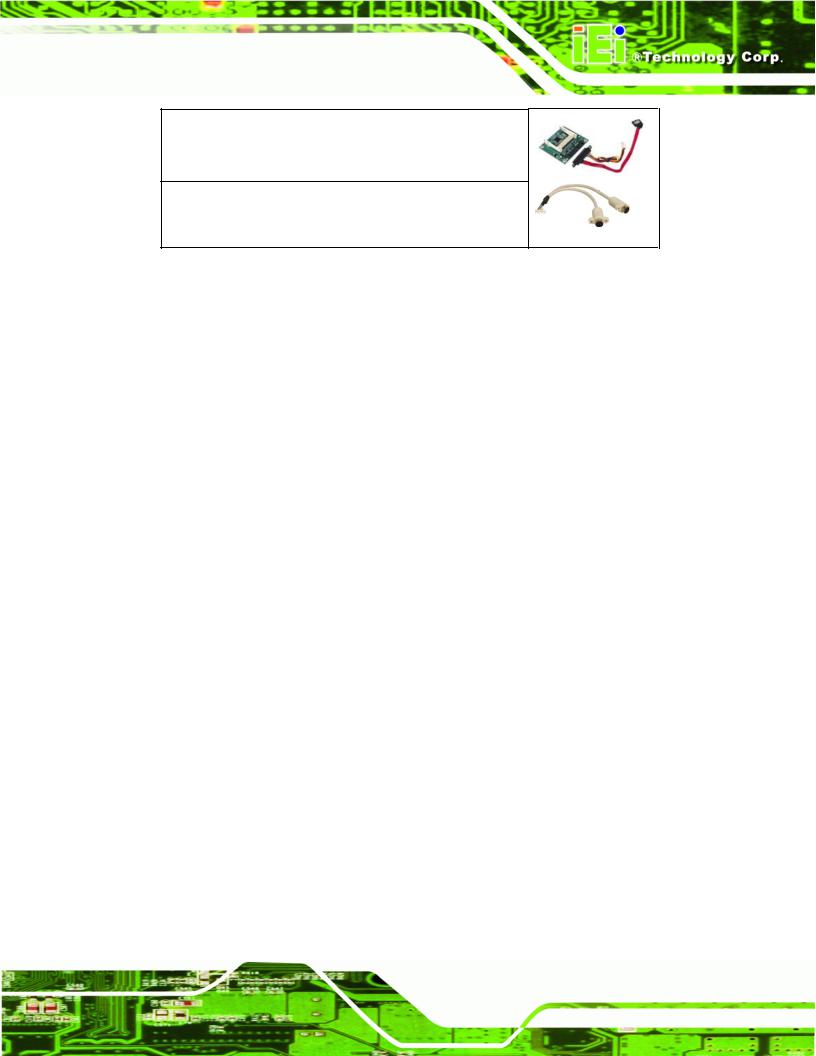
SATA to CF converter board (P/N: SACF-KIT01-R10)
Keyboard/Mouse Y cable (P/N: 32000-023800-RS)
Page 13
KINO-DH610
Chapter
3
Connectors
Page 14
KINO-DH610
3.1 Peripheral Interface Connectors
This chapter details all the jumpers and connectors.
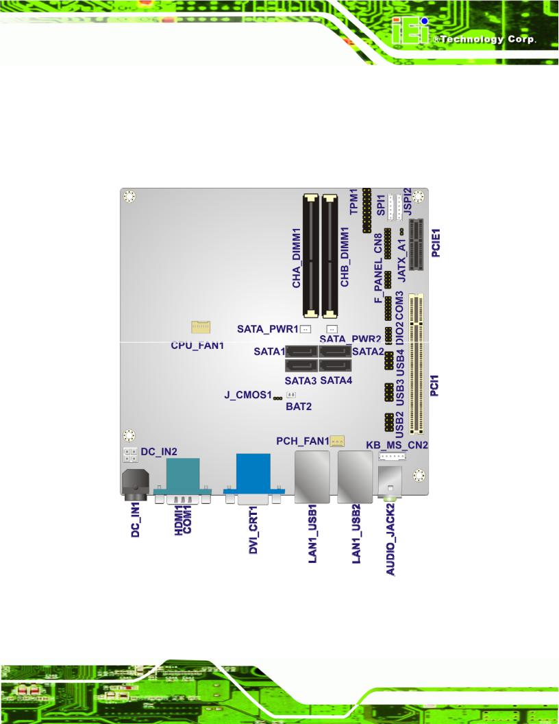
3.1.1 KINO-DH610 Layout
The figures below show all the connectors and jumpers.
Figure 3-1: Connector and Jumper Locations
Page 15
KINO-DH610
3.1.2 Peripheral Interface Connectors
The table below lists all the connectors on the board.
|
Connector |
|
Type |
Label |
|
|
|
|
|
|
Battery connector |
|
2-pin wafer |
BAT2 |
|
|
|
|
|
|
BIOS update connector |
|
6-pin header |
SPI1 |
|
|
|
|
|
|
DDR3 SO-DIMM slots |
|
DDR3 SO-DIMM slot |
CHA_DIMM1,CHB_DIMM1 |
|
|
|
|
|
|
Debug port connector |
|
18-pin header |
CN8 |
|
|
|
|
|
|
Digital I/O connector |
|
10-pin header |
DIO2 |
|
|
|
|
|
|
EC update connector |
|
6-pin header |
JSPI2 |
|
|
|
|
|
|
Fan connector (CPU) |
|
4-pin wafer |
CPU_FAN1 |
|
|
|
|
|
|
Fan connector (PCH) |
|
3-pin wafer |
PCH_FAN1 |
|
|
|
|
|
|
Front Panel connector |
|
10-pin header |
F_PANEL |
|
|
|
|
|
|
Keyboard and mouse connector |
|
6-pin wafer |
KB_MS_CN2 |
|
|
|
|
|
|
PCI slot |
|
PCI slot |
PCI1 |
|
|
|
|
|
|
PCIe x1 slot |
|
PCIe x1 slot |
PCIE1 |
|
|
|
|
|
|
Power connector |
|
4-pin header |
DC_IN2 |
|
|
|
|
|
|
SATA drive connector |
|
Serial ATA (SATA) |
SATA1, SATA2, SATA3, |
|
|
3Gb/s Connector |
SATA4 |
|
|
|
|
||
|
|
|
|
|
|
SATA power connector |
|
2-pin wafer |
SATA_PWR1, |
|
|
SATA_PWR2 |
||
|
|
|
|
|
|
|
|
|
|
|
Serial port connector (RS-232/422/485) |
|
14-pin header |
COM3 |
|
|
|
|
|
|
TPM connector |
|
20-pin connector |
TPM1 |
|
|
|
|
|
|
USB connector |
|
8-pin header |
USB2, USB3, USB4 |
|
|
|
|
|
Table 3-1: Peripheral Interface Connectors
Page 16

KINO-DH610
3.1.3 External Interface Panel Connectors
The table below lists the connectors on the external I/O panel.
Connector |
Type |
Label |
|
|
|
Audio connector |
Audio jack |
AUDIO_JACK2 |
|
|
|
Ethernet and USB connector |
RJ-45, USB port |
LAN1_USB1, |
|
|
LAN1_USB2 |
|
|
|
HDMI connector |
HDMI port |
HDMI1 |
|
|
|
Power connector |
4-pin Mini-DIN |
DC_IN1 |
|
|
|
RS-232 serial port |
DB-9 male |
COM1 |
|
|
|
VGA and DVI connector |
15-pin female, |
DVI_CRT1 |
|
24-pin female |
|
|
|
|
Table 3-2: Rear Panel Connectors |
|
|
3.2 Internal Peripheral Connectors
The section describes all of the connectors on the KINO-DH610.
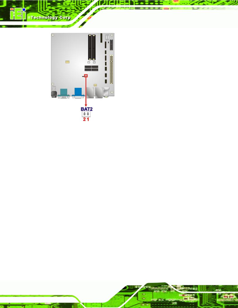
3.2.1 Battery Connector
CN Label: |
BAT2 |
CN Type: |
2-pin wafer |
CN Location: |
See Figure 3-2 |
CN Pinouts: |
See Table 3-3 |
The battery connector is connected to the system battery. The battery provides power to the system clock to retain the time when power is turned off.
Page 17
KINO-DH610
Figure 3-2: Battery Connector Location
PIN NO. |
DESCRIPTION |
PIN NO. |
DESCRIPTION |
|
|
|
|
|
|
|
|
1 |
VBATT |
2 |
GND |
|
|
|
|
Table 3-3: Battery Connector Pinouts
3.2.2 BIOS Update Connector
CN Label: |
SPI1 |
CN Type: |
6-pin wafer (1x6) |
CN Location: |
See Figure 3-3 |
CN Pinouts: |
See Table 3-4 |
The connector is for BIOS updating.
Page 18
Loading...