


 Loading...
MODEL:
AFL-15A-N270
Fanless All-in-one Panel PC with 1.6 GHz Intel® Atom™ Processor TFT LCD, Wireless LAN, Bluetooth, Touch Screen, RS-232/422/485 and IP 64 Protection
User Manual
Rev. 1.03 - 23 October, 2009

AFOLUX AFL-15A-N270 Panel PC
|
|
|
|
Revision |
|
|
|
|
|
|
|
|
|
|
|
|
|
|
Date |
Version |
Changes |
|
|
|
|
|
|
|
|
|
23 |
October, 2009 |
1.03 |
Modified Table 4-7 COM3 RX Function Select Jumper Settings |
|
|
|
|
|
|
|
|
30 |
September, 2009 |
1.02 |
Added back cover screw torque warning |
|
|
|
|
|
|
|
|
24 |
March, 2009 |
1.01 |
Changed model name |
|
|
|
|
|
|
|
|
20 |
January, 2009 |
1.00 |
Initial release |
|
|
|
|
|
|
|
Page II

AFOLUX AFL-15A-N270 Panel PC
Copyright
COPYRIGHT NOTICE
The information in this document is subject to change without prior notice in order to improve reliability, design and function and does not represent a commitment on the part of the manufacturer.
In no event will the manufacturer be liable for direct, indirect, special, incidental, or consequential damages arising out of the use or inability to use the product or documentation, even if advised of the possibility of such damages.
This document contains proprietary information protected by copyright. All rights are reserved. No part of this manual may be reproduced by any mechanical, electronic, or other means in any form without prior written permission of the manufacturer.
TRADEMARKS
All registered trademarks and product names mentioned herein are used for identification purposes only and may be trademarks and/or registered trademarks of their respective owners.
Page III
AFOLUX AFL-15A-N270 Panel PC
Packing List
 NOTE:
NOTE:
If any of the components listed in the checklist below are missing, please do not proceed with the installation. Contact the IEI reseller or vendor you purchased the AFL-15A-N270 from or contact an IEI sales representative directly. To contact an IEI sales representative, please send an email to sales@iei.com.tw.
The items listed below should all be included in the AFL-15A-N270 package.
1 x AFL-15A-N270 flat panel PC 1 x Power adapter
1 x Power cord
1 x Screw kit
1 x User manual CD and driver CD
1 x Touch pen
Images of the above items are shown in Chapter 3 on page 35.
Page IV
AFOLUX AFL-15A-N270 Panel PC
Table of Contents |
|
1 INTRODUCTION........................................................................................................ |
14 |
1.1 AFL-15A-N270 FLAT PANEL PC OVERVIEW ........................................................... |
15 |
1.1.1 Features and Model Variations........................................................................ |
15 |
1.1.2 Applications ..................................................................................................... |
16 |
1.2 EXTERNAL OVERVIEW.............................................................................................. |
16 |
1.2.1 General Description......................................................................................... |
16 |
1.2.2 Front Panel ...................................................................................................... |
17 |
1.2.3 Rear Panel ....................................................................................................... |
18 |
1.2.4 I/O Interface Panel .......................................................................................... |
18 |
1.3 INTERNAL OVERVIEW............................................................................................... |
19 |
1.4 SYSTEM SPECIFICATIONS.......................................................................................... |
19 |
2 DETAILED SPECIFICATIONS ................................................................................ |
22 |
2.1 AFL-15A-N270 DIMENSIONS .................................................................................. |
23 |
2.2 INTEL® ATOM™ PROCESSOR ................................................................................... |
24 |
2.3 MOTHERBOARD COMPONENTS................................................................................. |
24 |
2.3.1 Memory Support............................................................................................... |
24 |
2.3.1.1 Installed Memory...................................................................................... |
24 |
2.3.1.2 Additional Memory................................................................................... |
25 |
2.3.2 Storage Capacity.............................................................................................. |
25 |
2.4 EXTERNAL PERIPHERAL INTERFACE CONNECTORS................................................... |
25 |
2.4.1 Serial Port Connectors .................................................................................... |
25 |
2.4.2 LAN Connectivity ............................................................................................. |
26 |
2.4.3 External USB Connectors................................................................................ |
27 |
2.5 AFOLUX AFL-15A-N270 FRONT SIDE .................................................................. |
27 |
2.5.1 Monitor ............................................................................................................ |
27 |
2.5.2 Touch-Screen Module....................................................................................... |
28 |
2.6 GRAPHICS ................................................................................................................ |
28 |
2.6.1 Intel® 945GSE Integrated Graphics Media Accelerator 950 .......................... |
28 |
2.6.2 Dual-Display.................................................................................................... |
28 |
2.7 AUDIO ...................................................................................................................... |
28 |
Page V

|
AFOLUX AFL-15A-N270 Panel PC |
2.7.1 HD Audio Codec Controller ............................................................................ |
28 |
2.7.2 Stereo Speakers ................................................................................................ |
29 |
2.8 SYSTEM POWER ....................................................................................................... |
29 |
2.8.1 Power Mode ..................................................................................................... |
29 |
2.8.1.1 ATX Power Mode (Default)...................................................................... |
29 |
2.8.1.2 AT Power Mode ........................................................................................ |
30 |
2.8.2 Power Adapter ................................................................................................. |
30 |
2.8.3 Power Connector ............................................................................................. |
30 |
2.9 WIRELESS CONNECTIONS......................................................................................... |
31 |
2.9.1 USB Bluetooth Module .................................................................................... |
31 |
2.9.2 Wireless Ethernet ............................................................................................. |
31 |
3 UNPACKING ............................................................................................................... |
33 |
3.1 UNPACKING.............................................................................................................. |
34 |
3.1.1 Packing List ..................................................................................................... |
35 |
4 INSTALLATION ......................................................................................................... |
37 |
4.1 ANTI-STATIC PRECAUTIONS ...................................................................................... |
38 |
4.2 INSTALLATION PRECAUTIONS ................................................................................... |
38 |
4.3 PREINSTALLED COMPONENTS................................................................................... |
39 |
4.4 INSTALLATION AND CONFIGURATION STEPS ............................................................. |
39 |
4.5 REMOVING THE REAR PANEL ................................................................................... |
40 |
4.6 CF CARD INSTALLATION .......................................................................................... |
40 |
4.7 HDD INSTALLATION................................................................................................. |
41 |
4.8 AT/ATX MODE SELECTION...................................................................................... |
43 |
4.8.1 AT Power Mode................................................................................................ |
43 |
4.8.2 ATX Power Mode ............................................................................................. |
43 |
4.9 JUMPER SETTINGS .................................................................................................... |
44 |
4.9.1 Access the Jumpers .......................................................................................... |
45 |
4.9.2 Preconfigured Jumpers .................................................................................... |
45 |
4.9.3 CF Card Setup ................................................................................................. |
46 |
4.9.4 Clear CMOS Jumper........................................................................................ |
47 |
4.9.5 COM Port Pin 9 Select .................................................................................... |
48 |
4.9.6 COM3 RX Function Select Jumper.................................................................. |
49 |
4.9.7 COM3 TX Function Select Jumper .................................................................. |
50 |
Page VI
AFOLUX AFL-15A-N270 Panel PC |
|
4.9.8 COM3 RS-232/422/485 Serial Port Select Jumper ......................................... |
51 |
4.9.8.1 COM3 RS-422 and RS-485 Pinouts ......................................................... |
53 |
4.10 MOUNTING THE SYSTEM ........................................................................................ |
53 |
4.10.1 Wall Mounting................................................................................................ |
54 |
4.10.2 Panel Mounting.............................................................................................. |
56 |
4.10.3 Arm Mounting ................................................................................................ |
58 |
4.10.4 Cabinet and Rack Installation ....................................................................... |
60 |
4.11 BOTTOM PANEL CONNECTORS................................................................................ |
61 |
4.11.1 LAN Connection ............................................................................................. |
61 |
4.11.2 Serial Device Connection............................................................................... |
62 |
4.11.3 USB Device Connection................................................................................. |
63 |
5 SYSTEM MAINTENANCE ....................................................................................... |
64 |
5.1 SYSTEM MAINTENANCE INTRODUCTION .................................................................. |
65 |
5.2 ANTI-STATIC PRECAUTIONS ...................................................................................... |
65 |
5.3 TURN OFF THE POWER.............................................................................................. |
66 |
5.4 OPENING THE SYSTEM.............................................................................................. |
66 |
5.4.1 Removing the Back Panel ................................................................................ |
66 |
5.4.2 Internal Aluminum Cover Removal.................................................................. |
67 |
5.5 REPLACING COMPONENTS........................................................................................ |
68 |
5.5.1 Memory Module Replacement ......................................................................... |
68 |
5.5.2 CF Card Replacement...................................................................................... |
69 |
5.6 REINSTALLING THE COVERS ..................................................................................... |
69 |
6 AMI BIOS SETUP ....................................................................................................... |
71 |
6.1 INTRODUCTION......................................................................................................... |
72 |
6.1.1 Starting Setup................................................................................................... |
72 |
6.1.2 Using Setup ...................................................................................................... |
72 |
6.1.3 Getting Help..................................................................................................... |
73 |
6.1.4 Unable to Reboot After Configuration Changes.............................................. |
73 |
6.1.5 BIOS Menu Bar................................................................................................ |
73 |
6.2 MAIN........................................................................................................................ |
74 |
6.3 ADVANCED ............................................................................................................... |
75 |
6.3.1 CPU Configuration.......................................................................................... |
76 |
6.3.2 IDE Configuration ........................................................................................... |
77 |
Page VII

|
AFOLUX AFL-15A-N270 Panel PC |
6.3.2.1 IDE Master, IDE Slave ............................................................................. |
79 |
6.3.3 Super IO Configuration ................................................................................... |
84 |
6.3.4 Hardware Health Configuration...................................................................... |
87 |
6.3.5 Power Configuration........................................................................................ |
91 |
6.3.5.1 ACPI configuration ................................................................................... |
91 |
6.3.6 APM Configuration.......................................................................................... |
92 |
6.3.7 Remote Configuration ...................................................................................... |
95 |
6.3.8 USB Configuration........................................................................................... |
98 |
6.4 PCI/PNP................................................................................................................... |
99 |
6.5 BOOT...................................................................................................................... |
102 |
6.5.1 Boot Settings Configuration........................................................................... |
102 |
6.6 SECURITY............................................................................................................... |
105 |
6.7 CHIPSET ................................................................................................................. |
106 |
6.7.1 North Bridge Chipset Configuration ............................................................. |
107 |
6.7.2 SouthBridge Configuration............................................................................ |
109 |
6.8 EXIT ........................................................................................................................ |
110 |
7 SOFTWARE DRIVERS ............................................................................................. |
112 |
7.1 AVAILABLE SOFTWARE DRIVERS ............................................................................. |
113 |
7.2 STARTING THE DRIVER PROGRAM ........................................................................... |
113 |
7.3 CHIPSET DRIVER INSTALLATION.............................................................................. |
114 |
7.4 VGA DRIVER INSTALLATION................................................................................... |
119 |
7.5 AUDIO DRIVER INSTALLATION ............................................................................... |
124 |
7.5.1 BIOS Setup ..................................................................................................... |
124 |
7.5.2 Driver Installation ......................................................................................... |
124 |
7.6 LAN DRIVER INSTALLATION.................................................................................. |
127 |
7.7 TOUCH SCREEN DRIVER......................................................................................... |
130 |
7.8 BLUETOOTH DRIVER .............................................................................................. |
133 |
7.9 WIRELESS DRIVER ................................................................................................. |
137 |
A SYSTEM SPECIFICATIONS.................................................................................. |
141 |
A.1 MOTHERBOARD SPECIFICATIONS........................................................................... |
142 |
A.2 PROCESSOR SPECIFICATIONS ................................................................................. |
142 |
A.3 BLUETOOTH MODULE SPECIFICATIONS ................................................................. |
143 |
B SAFETY PRECAUTIONS ....................................................................................... |
144 |
Page VIII

AFOLUX AFL-15A-N270 Panel PC |
|
B.1 SAFETY PRECAUTIONS........................................................................................... |
145 |
B.1.1 General Safety Precautions ........................................................................... |
145 |
B.1.2 Anti-static Precautions .................................................................................. |
146 |
B.2 MAINTENANCE AND CLEANING PRECAUTIONS ...................................................... |
146 |
B.2.1 Maintenance and Cleaning............................................................................ |
146 |
B.2.2 Cleaning Tools ............................................................................................... |
147 |
C BIOS CONFIGURATION OPTIONS..................................................................... |
149 |
C.1 BIOS CONFIGURATION OPTIONS ........................................................................... |
150 |
D WATCHDOG TIMER .............................................................................................. |
153 |
E HAZARDOUS MATERIALS DISCLOSURE ....................................................... |
156 |
E.1 HAZARDOUS MATERIAL DISCLOSURE TABLE FOR IPB PRODUCTS CERTIFIED AS |
|
ROHS COMPLIANT UNDER 2002/95/EC WITHOUT MERCURY ..................................... |
157 |
Page IX

AFOLUX AFL-15A-N270 Panel PC
List of Figures |
|
Figure 1-1: AFL-15A-N270 Flat Panel PC ................................................................................... |
15 |
Figure 1-2: AFL-15A-N270 Front View ........................................................................................ |
17 |
Figure 1-3: AFL-15A-N270 Rear View ......................................................................................... |
18 |
Figure 1-4: AFL-15A-N270 I/O Interface Connector Panel........................................................ |
19 |
Figure 2-1: AFL-15A-N270 Dimensions (mm) ............................................................................ |
23 |
Figure 2-2: Preinstalled DDR2 SO-DIMM.................................................................................... |
25 |
Figure 2-3: COM Ports.................................................................................................................. |
26 |
Figure 2-4: RJ-45 Ethernet Connectors...................................................................................... |
26 |
Figure 2-5: External USB Ports ................................................................................................... |
27 |
Figure 2-6: LCD Screen................................................................................................................ |
27 |
Figure 2-7: VGA Connector ......................................................................................................... |
28 |
Figure 2-8: Audio Jack ................................................................................................................. |
29 |
Figure 2-9: Stereo Speakers ........................................................................................................ |
29 |
Figure 2-10: Power Connector .................................................................................................... |
30 |
Figure 2-11: PIFA Antenna and Wireless Module...................................................................... |
32 |
Figure 4-1: Back Cover Retention Screws ................................................................................. |
40 |
Figure 4-2: CF Card Location ...................................................................................................... |
41 |
Figure 4-3: HDD Bracket Retention Screws............................................................................... |
42 |
Figure 4-4: AFL-15A-N270 HDD Retention Screws ................................................................... |
42 |
Figure 4-5: AT/ATX Switch Location........................................................................................... |
43 |
Figure 4-6: CF Card Setup Jumper Location ............................................................................. |
46 |
Figure 4-7: Clear CMOS Jumper ................................................................................................. |
48 |
Figure 4-8: COM1 and COM3 Pin 9 Setting Jumper Locations................................................ |
49 |
Figure 4-9: COM3 RX Function Select Jumper Location.......................................................... |
50 |
Figure 4-10: COM3 TX Function Select Jumper Pinout Locations.......................................... |
51 |
Figure 4-11: COM3 RS-232/422/485 Serial Port Select Jumper Location................................ |
52 |
Figure 4-12: Wall-mounting Bracket........................................................................................... |
54 |
Figure 4-13: Chassis Support Screws........................................................................................ |
55 |
Figure 4-14: Secure the Panel PC ............................................................................................... |
56 |
Figure 4-15: AFL-15A-N270 Panel Opening (Unit: mm) ............................................................ |
57 |
Figure 4-16: Panel Mounting ....................................................................................................... |
58 |
Page X
AFOLUX AFL-15A-N270 Panel PC
Figure 4-17: Arm Mounting Retention Screw Holes.................................................................. |
59 |
Figure 4-18: The Rack/Cabinet Bracket...................................................................................... |
60 |
Figure 4-19: LAN Connection ...................................................................................................... |
61 |
Figure 4-20: Serial Device Connector......................................................................................... |
62 |
Figure 4-21: USB Device Connection ......................................................................................... |
63 |
Figure 5-1: Back Cover Retention Screws ................................................................................. |
67 |
Figure 5-2: Aluminum Back Cover Retention Screws .............................................................. |
67 |
Figure 5-3: SO-DIMM Socket Location ....................................................................................... |
68 |
Figure 5-4: DDR SO-DIMM Module Installation.......................................................................... |
69 |
Figure 7-3: Drivers..................................................................................................................... |
114 |
Figure 7-4: Chipset Driver Screen............................................................................................ |
115 |
Figure 7-5: Chipset Driver Welcome Screen........................................................................... |
115 |
Figure 7-6: Chipset Driver License Agreement ...................................................................... |
116 |
Figure 7-7: Chipset Driver Read Me File ................................................................................. |
117 |
Figure 7-8: Chipset Driver Setup Operations ......................................................................... |
118 |
Figure 7-9: Chipset Driver Installation Finish Screen............................................................ |
119 |
Figure 7-10: VGA Driver Read Me File..................................................................................... |
120 |
Figure 7-11: VGA Driver Setup Files Extracted ...................................................................... |
120 |
Figure 7-12: VGA Driver Welcome Screen .............................................................................. |
121 |
Figure 7-13: VGA Driver License Agreement.......................................................................... |
122 |
Figure 7-14: VGA Driver Read Me File..................................................................................... |
122 |
Figure 7-15: VGA Driver Setup Operations............................................................................. |
123 |
Figure 7-16: VGA Driver Installation Finish Screen ............................................................... |
123 |
Figure 7-17: The InstallShield Wizard Starts .......................................................................... |
124 |
Figure 7-18: Preparing Setup Screen ...................................................................................... |
125 |
Figure 7-19: InstallShield Wizard Welcome Screen ............................................................... |
125 |
Figure 7-20: Audio Driver Software Configuration................................................................. |
126 |
Figure 7-21: Installation Wizard Updates the System............................................................ |
126 |
Figure 7-22: Restart the Computer .......................................................................................... |
127 |
Figure 7-23: LAN Driver Welcome Screen .............................................................................. |
128 |
Figure 7-24: LAN Driver Welcome Screen .............................................................................. |
128 |
Figure 7-25: LAN Driver Installation ........................................................................................ |
129 |
Figure 7-26: LAN Driver Installation Complete....................................................................... |
130 |
Figure 7-27: Welcome Screen .................................................................................................. |
131 |
Figure 7-28: License Agreement.............................................................................................. |
131 |
Page XI

AFOLUX AFL-15A-N270 Panel PC |
|
Figure 7-29: Ready to Install the Program .............................................................................. |
132 |
Figure 7-30: Installing PenMount DMC9000............................................................................ |
132 |
Figure 7-31: Reboot the Computer .......................................................................................... |
133 |
Figure 7-32: Bluetooth Driver Icon........................................................................................... |
133 |
Figure 7-33: Welcome Screen .................................................................................................. |
134 |
Figure 7-34: License Agreement.............................................................................................. |
134 |
Figure 7-35: Bluetooth Driver Setup Options ......................................................................... |
135 |
Figure 7-36: Bluetooth Driver Destination Folder .................................................................. |
135 |
Figure 7-37: Ready to Install the Program .............................................................................. |
136 |
Figure 7-38: Installing BlueSoleil ............................................................................................. |
136 |
Figure 7-39: Bluetooth Driver Complete Installation Screen ................................................ |
137 |
Figure 7-40: Reboot the Computer .......................................................................................... |
137 |
Figure 7-41: Wireless Driver OS Folders................................................................................. |
138 |
Figure 7-42: Wireless Driver License Agreement................................................................... |
138 |
Figure 7-43: Wireless Driver Configuration Tool Options..................................................... |
139 |
Figure 7-44: Wireless Mode Select Window ........................................................................... |
139 |
Figure 7-45: Wireless Driver Installation................................................................................. |
140 |
Page XII

AFOLUX AFL-15A-N270 Panel PC
List of Tables |
|
Table 1-1: Model Variations ......................................................................................................... |
16 |
Table 1-2: AFL-15A-N270 Series System Specifications.......................................................... |
21 |
Table 4-1: Jumpers....................................................................................................................... |
45 |
Table 4-2: Preconfigured Jumpers ............................................................................................. |
45 |
Table 4-3: CF Card Setup Jumper Settings ............................................................................... |
46 |
Table 4-4: Clear CMOS Jumper Settings.................................................................................... |
47 |
Table 4-5: COM1 Pin 9 Setting Jumper Settings ....................................................................... |
48 |
Table 4-6: COM3 Pin 9 Setting Jumper Settings ....................................................................... |
49 |
Table 4-7: COM3 RX Function Select Jumper Settings ............................................................ |
50 |
Table 4-8: COM3 TX Function Select Jumper Settings............................................................. |
51 |
Table 4-9: COM3 RS-232/422/485 Serial Port Select Jumper Settings.................................... |
52 |
Table 4-10: RS-422 Pinouts ......................................................................................................... |
53 |
Table 4-11: RS-485 Pinouts ......................................................................................................... |
53 |
Table 6-1: BIOS Navigation Keys ................................................................................................ |
73 |
Page XIII
AFOLUX AFL-15A-N270 Panel PC
Chapter
1
Introduction
Page XIV
AFOLUX AFL-15A-N270 Panel PC
1.1 AFL-15A-N270 Flat Panel PC Overview
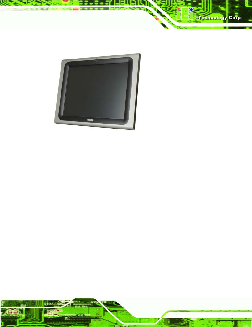
Figure 1-1: AFL-15A-N270 Flat Panel PC
The AFL-15A-N270 series is Intel® Atom™ powered flat panel PCs with a rich variety of functions and peripherals. All AFL-15A-N270 models are designed for easy and simplified integration in to kiosk and point-of-sales (POS) applications.
An Intel® 945GSE graphics memory controller hub (GMCH) coupled with an Intel® ICH7-M input/output controller hub ensures optimal memory, graphics, and peripheral I/O support. The system comes with 1.0 GB of preinstalled DDR2 SDRAM and supports a maximum of 2.0 GB of DDR2 SDRAM ensuring smooth data throughputs with reduced bottlenecks and fast system access.
Two serial ports and four external USB 2.0 ports ensure simplified connectivity to a variety of external peripheral devices. Wi-Fi capabilities and two RJ-45 GbE connectors ensure smooth connection of the system to the external LAN.
1.1.1 Features and Model Variations
There are four models in the AFL-15A-N270 series. Both models feature the following:
Intel® Atom™ processor Intel® 945GSE chipset
1.0 GB 533 MHz DDR2 SDRAM preinstalled
Page 15

AFOLUX AFL-15A-N270 Panel PC
802.11 b/g wireless module Four USB 2.0 ports
Watchdog timer that triggers a system reset if the system hangs for some reason
IP 64 compliant front panel AT or ATX power mode Touch screen
Bluetooth
Optional HSDPA module support RoHS compliance
There are four kinds of panel size of the AFL-15A-N270 series. The model numbers and model variations are listed below.
Model |
Brightness |
CPU |
HSDPA01 |
|
|
|
|
AFL-15A-N270/WT-R/1GB |
350 cd/m2 |
Intel® Atom™ N270 |
No |
|
|
|
|
AFL-15AE-N270/WT-R/1GB |
250 cd/m2 |
Intel® Atom™ N270 |
No |
|
|
|
|
AFL-15A-N270/WT-R/1GB/HSDPA 01 |
350 cd/m2 |
Intel® Atom™ N270 |
Yes |
|
|
|
|
AFL-15AE-N270/WT-R/1GB/HSDPA 01 |
250 cd/m2 |
Intel® Atom™ N270 |
Yes |
|
|
|
|
Table 1-1: Model Variations |
|
|
|
|
|
|
|
1.1.2 Applications
The AFL-15A-N270 panel PCs are elegant yet sophisticated systems that are easily implemented in commercial environments, industrial environments and corporate environments.
1.2External Overview
1.2.1General Description
The stylish AFL-15A-N270 panel PC comprises of a screen, rear panel and bottom panel. An ABS/PC plastic front frame surrounds the front screen. The rear panel provides screw holes for a wall-mounting bracket compliant with VESA FDMI standard. An I/O interface
Page 16
AFOLUX AFL-15A-N270 Panel PC
panel on the bottom panel of the AFL-15A-N270 provides access to external interface connectors that include LAN, USB 2.0, serial port, reset button, VGA, audio connector, power connector and power switch.
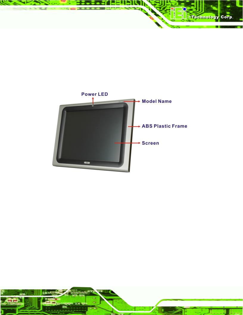
1.2.2 Front Panel
The front side of the AFL-15A-N270 series is a flat panel TFT LCD screen surrounded by an ABS/PC plastic frame. The top of the front panel has a power LED.
Figure 1-2: AFL-15A-N270 Front View
Page 17
AFOLUX AFL-15A-N270 Panel PC
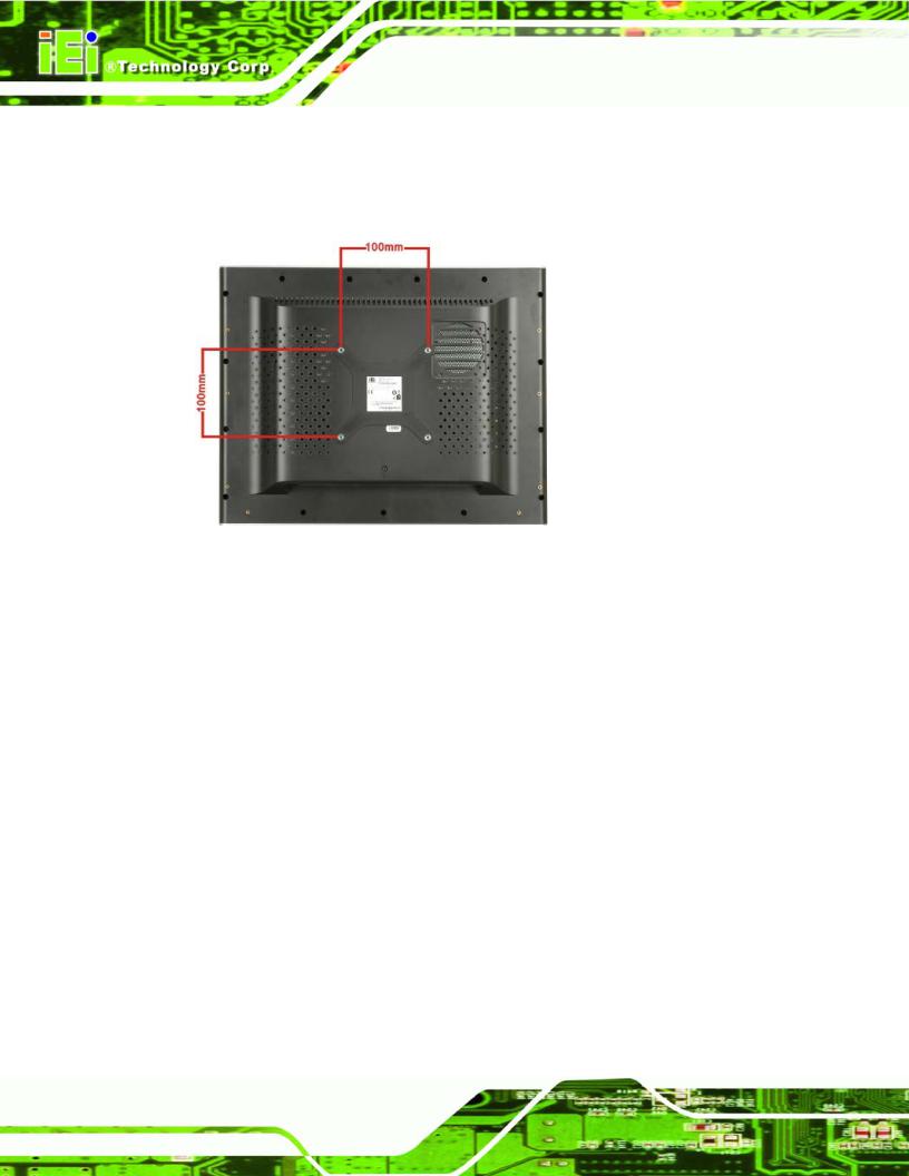
1.2.3 Rear Panel
The rear panel provides access to retention screw holes that support the wall mounting. Refer to Figure 1-3.
Figure 1-3: AFL-15A-N270 Rear View
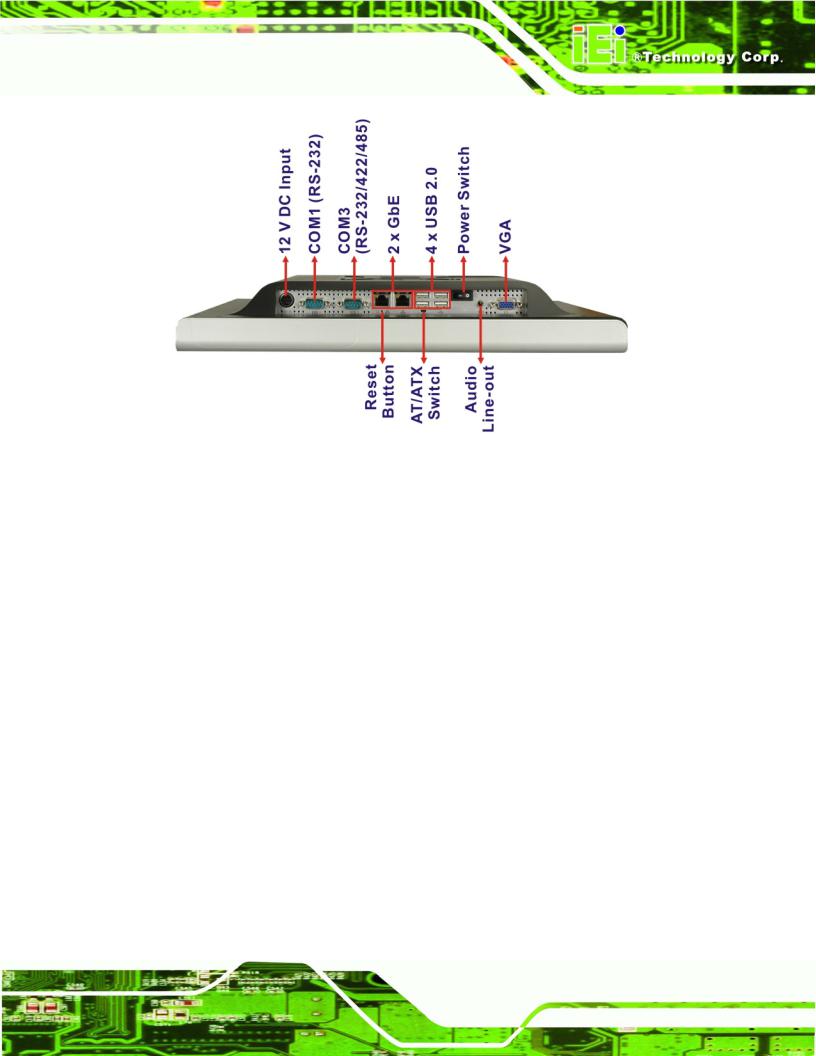
1.2.4 I/O Interface Panel
The I/O interface panel located on the bottom of the AFL-15A-N270 has the following I/O interface connectors:
1 x 12 V DC In connector
1 x RS-232 connector
1 x RS-232/422/485 connector
2 x GbE LAN connectors
4 x USB 2.0 connectors
1 x Audio line-out connector
1 x VGA connector
1 x Power switch
1 x Reset button
1 x AT/ATX power mode switch
The external I/O interface connector panel is shown in Figure 1-4.
Page 18
AFOLUX AFL-15A-N270 Panel PC
Figure 1-4: AFL-15A-N270 I/O Interface Connector Panel
1.3 Internal Overview
The AFOLUX AFL-15A-N270 has the following components installed internally:
1 x Motherboard
1 x 1.0 GB 533 MHz DDR2 SDRAM SO-DIMM 1 x Wireless module
1 x Bluetooth module
1.4 System Specifications
The technical specifications for the AFOLUX AFL-15A-N270 series systems are listed in
Table 1-2.
Specification |
AFL-15A-N270 |
AFL-15AE-N270 |
|
|
|
LCD Size |
15” |
15” |
|
|
|
Max. Resolution |
1024 x 768 |
1024 x 768 |
|
|
|
Contrast Ratio |
700:1 |
600:1 |
|
|
|
Brightness (cd/m2) |
350 |
250 |
LCD Color |
262K |
16.7M |
|
|
|
Page 19

|
AFOLUX AFL-15A-N270 Panel PC |
||
|
|
|
|
Pixel Pitch (H x V) (mm) |
0.297 x 0.297 |
0.297 x 0.297 |
|
|
|
|
|
Viewing Angle (H-V) |
140 / 125 |
|
160/160 |
|
|
|
|
Backlight MTBF |
50,000 hours |
40,000 hours |
|
|
|
|
|
SBC Model |
AFLMB2-945GSE |
|
|
|
|
|
|
CPU |
1.6 GHz Intel® Atom™ N270 processor |
||
|
|
|
|
Chipset |
Intel® 945GSE + ICH7-M |
|
|
|
|
|
|
Memory |
One 1.0 GB 533 MHz DDR2 SDRAM SO-DIMM pre-installed |
||
|
(Supports up to 2 GB 400 MHz or 533 MHz DDR2 SDRAM) |
||
|
|
|
|
SSD |
CF Type II slot |
|
|
|
|
|
|
Watchdog Timer |
Software Programmable supports 1 sec. ~ 255 sec. system reset |
||
|
|
|
|
Audio |
AMP 1.5 W + AMP 1.5 W (built-in stereo speakers) |
||
|
|
|
|
Expansion |
1 x PCIe mini card (wireless LAN 802.11 b/g module) |
||
|
|
|
|
|
1 x Bluetooth module (USB interface, Bluetooth v 2.0) |
||
|
|
|
|
HDD Drive Bay |
1 x 2.5” SATA HDD bay or HSDPA module |
||
|
|
|
|
Construction Material |
ABS + PC plastic front frame |
|
|
|
|
|
|
Mounting |
Panel |
|
|
|
Wall |
|
|
|
Rack |
|
|
|
Stand |
|
|
|
Arm (VESA 75 mm x 75 mm or 100 mm x 100 mm) |
||
|
|
|
|
Front Panel Color |
Silver and Black |
|
|
|
|
|
|
Dimensions (mm) |
394 mm x 309 mm x 61 mm (W x H x D) |
||
|
|
|
|
Operation Temperature |
0ºC ~ 50ºC with CF card or 2.5” SSD SATA HDD |
||
|
0ºC ~ 40ºC with SATA HDD |
|
|
|
|
|
|
Storage Temperature |
-20ºC ~ 60ºC |
|
|
|
|
|
|
Net weight |
3.2kg |
|
|
|
|
|
|
IP level (front panel) |
IP 64 |
|
|
|
|
|
|
EMC |
CE, FCC and CCC |
|
|
|
|
|
|
Safety |
CB |
|
|
|
|
|
|
Touch Screen |
Resistive Type 5-wire (touch controller is on board) |
||
|
|
|
|
Power Adapter |
60 W |
|
|
|
|
|
|
|
Input: 90 VAC ~ 264 VAC @ 50 Hz / 60 Hz |
||
|
|
|
|
|
Output: 12 V DC |
|
|
|
|
|
|
Power Consumption |
41 W |
|
40 W |
|
|
|
|
Page 20
AFOLUX AFL-15A-N270 Panel PC
I/O Ports and Switches |
1 x 12 V DC input jack |
|
|
|
1 x Audio line-out connector |
|
|
|
1 x RS-232 COM port connector |
|
|
|
1 x RS-232/422/485 COM port connector |
|
|
|
2 x RJ-45 for GbE LAN |
|
|
|
4 x USB 2.0 ports |
|
|
|
1 x VGA connector |
|
|
|
1 x Power switch |
|
|
|
1 x AT/ATX power mode switch |
|
|
|
1 x Reset button |
|
|
Table 1-2: AFL-15A-N270 Series System Specifications
Page 21
AFOLUX AFL-15A-N270 Panel PC
Chapter
2
Detailed Specifications
Page 22

AFOLUX AFL-15A-N270 Panel PC
2.1 AFL-15A-N270 Dimensions
The AFL-15A-N270 dimensions are shown in Figure 2-1 and listed below.
Width: |
393.04 mm |
Height: |
308.06 mm |
Depth: |
61.00 mm |
Figure 2-1: AFL-15A-N270 Dimensions (mm)
Page 23

AFOLUX AFL-15A-N270 Panel PC
2.2 Intel® Atom™ Processor
A 45nm N270 Intel® Atom™ processor is installed in the system. The processor has a CPU speed of 1.6 GHz and a 533 MHz front side bus (FSB). The processor also comes with a 512 KB L2 cache and a 1.6 GHz L2 cache speed. Some of the features of the Intel® Atom™ processor N270 are listed below:
On-die, primary 32-kB instructions cache and 24-kB write-back data cache 533-MHz source-synchronous front side bus (FSB)
2-Threads support
On-die 512-kB, 8-way L2 cache Support for IA 32-bit architecture
Intel® Streaming SIMD Extensions-2 and -3 (Intel® SSE2 and Intel® SSE3) support and Supplemental Streaming SIMD Extension 3 (SSSE3) support Micro-FCBGA8 packaging technologies
Thermal management support via Intel® Thermal Monitor 1 and Intel Thermal Monitor 2
FSB Lane Reversal for flexible routing Supports C0/C1(e)/C2(e)/C4(e)
L2 Dynamic Cache Sizing
Advanced power management features including Enhanced Intel SpeedStep® Technology
Execute Disable Bit support for enhanced security
2.3 Motherboard Components
The following sections describe some of the features on the motherboard.
2.3.1Memory Support
2.3.1.1Installed Memory
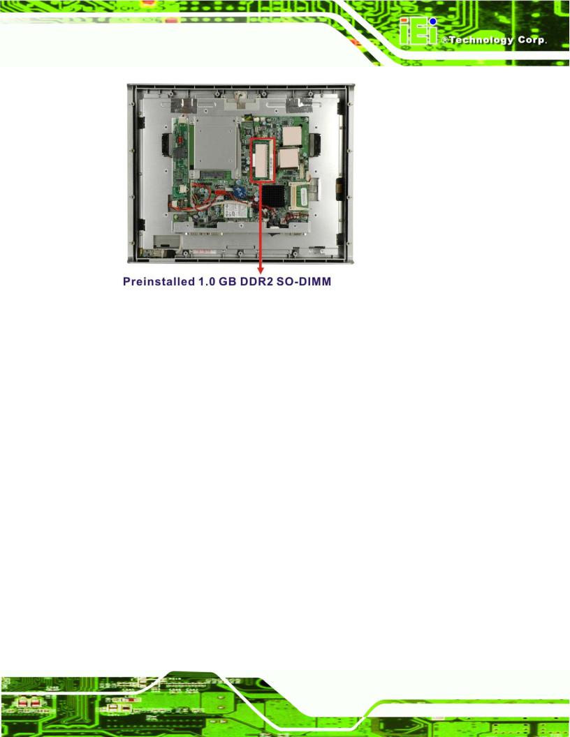
One 200-pin 1.0 GB 533 MHz DDR2 SDRAM SO-DIMM is installed in the AFL-15A-N270 and controlled by the Intel® 945GSE GMCH installed on the internal motherboard.
Page 24
AFOLUX AFL-15A-N270 Panel PC
Figure 2-2: Preinstalled DDR2 SO-DIMM
2.3.1.2 Additional Memory
The Intel® 945GSE is capable of supporting one 200-pin 2.0 GB (max.) 400 MHz or 533 MHz DDR2 SDRAM SO-DIMM. If additional memory is required, please contact an IEI sales representative and discuss the necessary system requirement.
2.3.2 Storage Capacity
The AFL-15A-N270 series supports an easily installed CompactFlash® Type II (CF Type II) memory disk. The AFL-15A-N270 also supports a 2.5” SATA drive through the on-board SATA connector inside the chassis.
2.4 External Peripheral Interface Connectors
The following section describes the external peripheral interface connectors on the bottom panel of the subsystem.
2.4.1 Serial Port Connectors
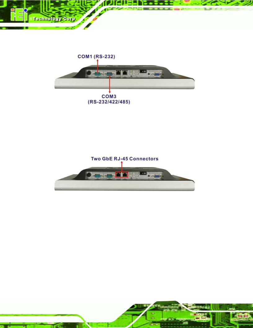
The AFL-15A-N270 has two serial ports. One of these ports (COM1) is RS-232 only port. The other serial port (COM3) can be configured as a RS-232, RS-422 or an RS-485 serial port. Pin 9 on both ports can be set as the normal ring (RI) signal or can be designated as
Page 25
AFOLUX AFL-15A-N270 Panel PC
a 5 V or 12 V power supply. Enabling COM devices to be powered through the COM port eliminates unnecessary and messy cabling.
Figure 2-3: COM Ports
2.4.2 LAN Connectivity
The AFL-15A-N270 has two RJ-45 LAN connectors on the bottom panel.
Figure 2-4: RJ-45 Ethernet Connectors
The PCIe lane from the Intel® ICH7 chipset of the AFL-15A-N270 is interfaced to the Realtek RTL8111CP PCIe gigabit Ethernet (GbE) controllers. The RTL8111CP controllers are then connected directly to the RJ-45 connectors on the bottom panel and provides external GbE connectivity. Some of the RTL8111CP controller features are listed below:
Integrated 10/100/1000 transceiver
Supports PCI Express™ 1.1
Fully compliant with IEEE 802.3, IEEE 802.3u, IEEE 802.3ab
Supports IEEE 802.1P Layer 2 Priority Encoding
Supports IEEE 802.1Q VLAN tagging
Serial EEPROM
Page 26
AFOLUX AFL-15A-N270 Panel PC
Transmit/Receive on-chip buffer support 64-pin QFN package (Green package)
2.4.3 External USB Connectors
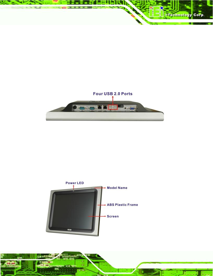
There are four USB 2.0 connectors on the bottom panel of the AFL-15A-N270. All USB 2.0 connectors are interfaced directly to the USB controllers on the ICH7-M southbridge. These USB connectors are fully compliant with USB specification Revision 2.0 and USB specification Revision 1.1 and can be interfaced to both USB 1.1 and USB 2.0 compliant devices.
Figure 2-5: External USB Ports
2.5AFOLUX AFL-15A-N270 Front Side
2.5.1Monitor
A 15” XGA LCD screen is installed on the front of the AFOLUX AFL-15A-N270 series. The installed monitor has a pixel resolution of 1024 x 768 pixels. The screen is shown in
Figure 2-6 below.
Figure 2-6: LCD Screen
Page 27
AFOLUX AFL-15A-N270 Panel PC
2.5.2 Touch-Screen Module
A controller for the 5-wire resistive touch screen is installed on the motherboard. The sensitive touch screen is accurate, reliable and durable.
2.6Graphics
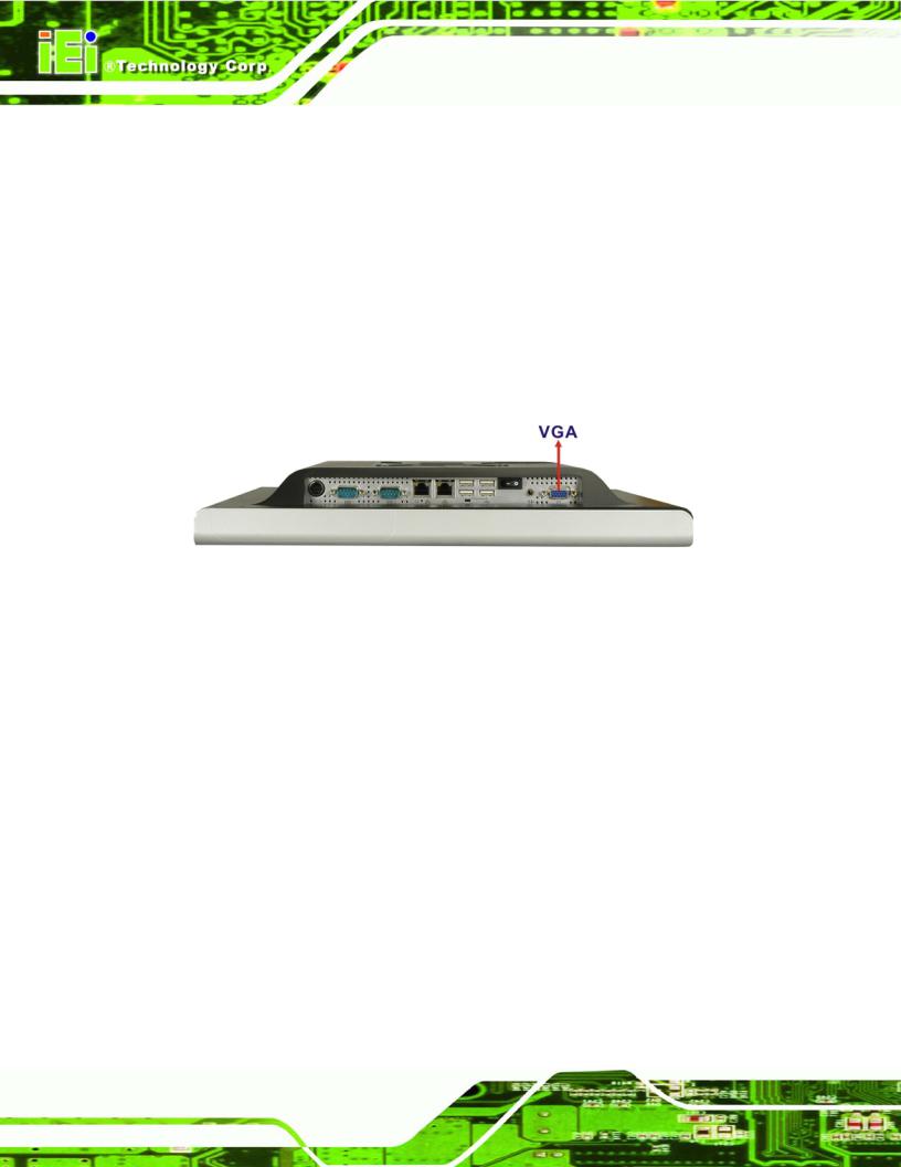
2.6.1Intel® 945GSE Integrated Graphics Media Accelerator 950
The Intel® 945GSE has the Intel® GMA 950 integrated into the chipset and interfaced to the VGA connector. The Intel® GMA 950 is a 400 MHz 256-bit graphics core and supports up to 10.6 GBps memory bandwidth with 667 MHz DDR2 system memory.
Figure 2-7: VGA Connector
2.6.2 Dual-Display
The system supports dual display capabilities. An additional monitor can be connected to the AFL-15A-N270 through the VGA connector described above.
2.7Audio
2.7.1HD Audio Codec Controller
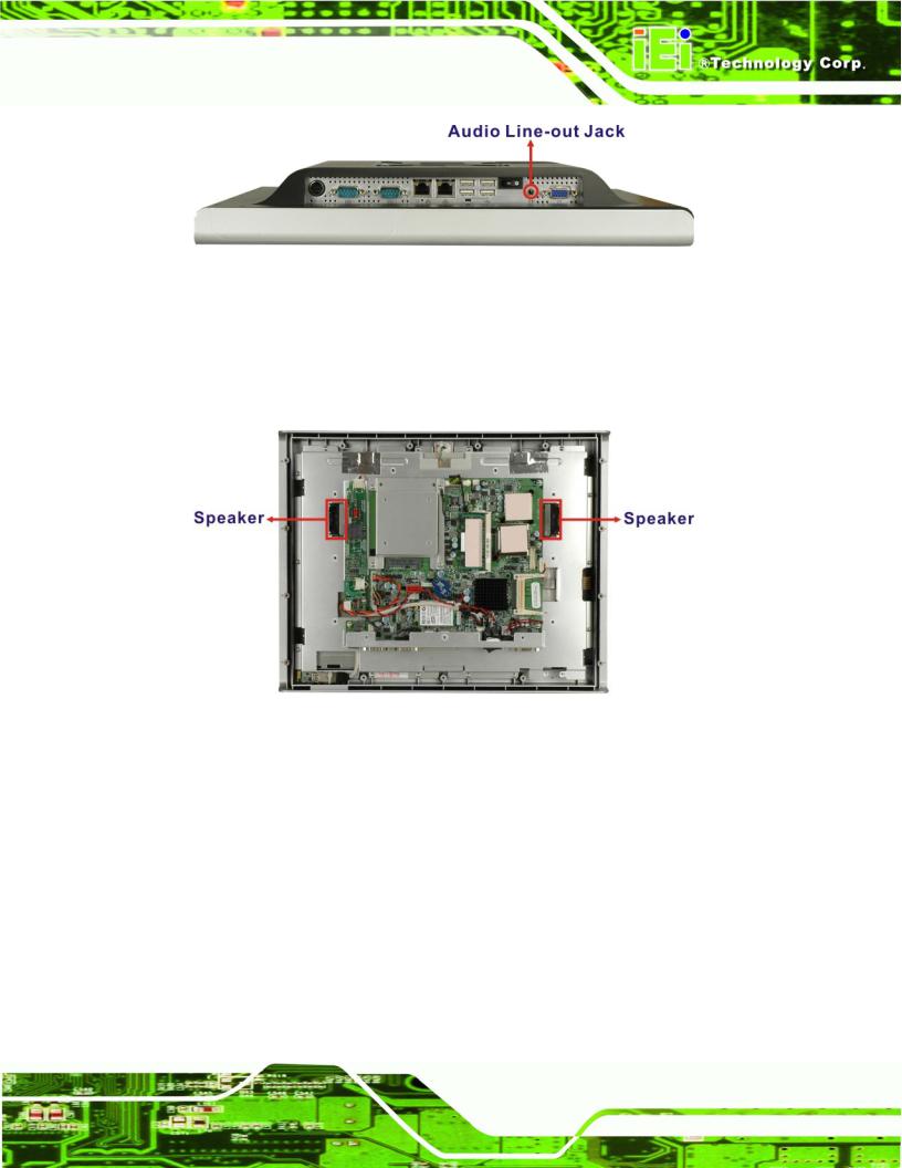
The integrated HD Audio compliant audio controller on the Intel® ICH7-M Southbridge is integrated to a RealTek ALC888 audio codec. The RealTek ALC888 is connected to an external audio line-out jack, which is then connected to compliant audio devices. The RealTek ALC888 is a 7.1+2 Channel High Definition Audio codec. The audio connector is shown in Figure 2-8.
Page 28
AFOLUX AFL-15A-N270 Panel PC
Figure 2-8: Audio Jack
2.7.2 Stereo Speakers
Two internal 1.5 W stereo speakers on the sides of the AFL-15A-N270 are interfaced to the system through a Philips TDA1517p integrated class-B dual output amplifier.
Figure 2-9: Stereo Speakers
2.8System Power
2.8.1Power Mode
The system can be run in the AT power mode or the ATX power mode. Both these power modes are described below.
2.8.1.1 ATX Power Mode (Default)
With the ATX mode selected, the AFOLUX AFL-15A-N270 panel PC goes in a standby mode when it is turned off. The panel PC can be easily turned on via network or a power switch in standby mode. Remote power control is perfect for advertising applications
Page 29
AFOLUX AFL-15A-N270 Panel PC
since the broadcasting time for each panel PC can be set individually and controlled remotely. Other possible application includes
Security surveillance
Point-of-Sale (POS)
Advertising terminal
2.8.1.2 AT Power Mode
With the AT mode selected, the power is controlled by a central power unit rather than a power switch. The AFOLUX AFL-15A-N270 panel PC turns on automatically when the power is connected. The AT mode benefits a production line to control multiple panel PCs from a central management center and other applications including:
ATM
Self-service kiosk
Plant environment monitoring system
Factory automation platform
Manufacturing shop flow
2.8.2 Power Adapter
The system is shipped with a 90 V to 264 V AC power adapter that has a maximum power output of 60 W. The power adapter has a 12 V DC output connector.
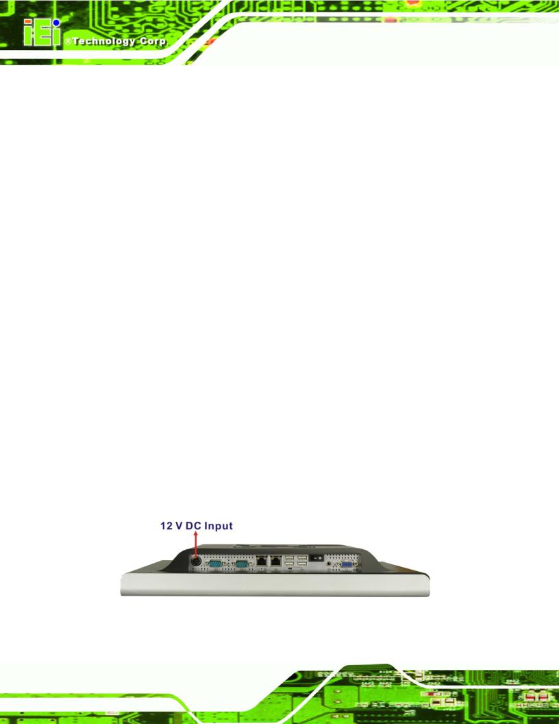
2.8.3 Power Connector
There is one 4-pin 12 V power input connector on the bottom panel. The power connector is shown in Figure 2-10 below.
Figure 2-10: Power Connector
Page 30
Loading...