


FT1A Series
Confirm that the delivered product is what you have ordered. Read this instruction sheet to
make sure of correct operation. Make sure that the instruction sheet is kept by the end
user.
This manual is the instruction sheet of the SmartAXIS Series FT1A Touch.
Unless otherwise specified, SmartAXIS refers to the SmartAXIS Series FT1A Touch.
Touch
The generic term for the SmartAXIS FT1A-*12RA-*, FT1A-*14KA-* and
FT1A-*14SA-*.
SAFETY PRECAUTIONS
● Be certain to read this manual carefully before performing installation, wiring, or
maintenance work, or operating the Touch.
● This product has been manufactured with careful regard to quality. However, if you
intend to use this product in applications where failure of this equipment may result in
damage to property or injury, ensure that it used in conjunction with appropriate fail-safe
backup equipment.
● In this manual, safety precautions are categorized in order of importance to Warning and
Caution:
Warning notices are used to emphasize that improper operation may cause severe
personal injury or death.
Caution notices are used where inattention might cause personal injury or damage to
equipment.
● The Touch is not intended to be used for applications which require high reliability and
safety, such as medical equipment, nuclear equipment, railways, aircraft, and vehicles.
The Touch cannot be used for these applications.
● For other applications which require high reliability in function and precision, provide a
failsafe design and redundant design for the entire system including the Touch.
• Emergency and interlocking circuits must be configured outside of the Touch.
• If relays in the Touch output circuits should fail, outputs may remain at on or off state.
For output signals which may cause serious accidents, configure monitor circuits
outside the Touch.
• The Touch self-diagnostic function may detect internal circuit or program errors, stop
programs, and turn outputs off. Configure circuits so that the system containing the
Touch are not jeopardized when outputs turn off.
1

● Emergency and interlocking circuits must be configured outside of the Touch.
Do not use the Touch’s internal touch switches for an emergency circuit. If the Touch
failed, the external equipment connected to the Touch will no longer be protected and
serious injury to operators and equipment damage may be caused.
● Turn off the power to the Touch before installation, removal, wiring, maintenance, and
inspection of the Touch. Failure to turn power off may cause electrical shock or fire
hazard.
● Special expertise is required to install, wire, configure, and operate the Touch. People
without such expertise must not use the Touch.
● The Touch uses an LCD (liquid crystal display) as a display device. The liquid inside the
LCD is harmful to the skin. If the LCD is broken and the liquid attaches to your skin or
clothes, wash the liquid off using soap, and consult a doctor immediately.
● Prevent the Touch from falling while moving or transporting, otherwise damage or
malfunction of the Touch will result.
● Use the product within the environmental limits given in the catalog and manual. Use of
the product in high-temperature or high-humidity environments, or in locations where it
is exposed to condensation, corrosive gas or large shock loads can create the risk of
electrocution and fire.
● The Touch is designed for use in pollution degree 2. Use the Touch in environments of
pollution degree 2. (based on the IEC60664-1 rating)
● Install the Touch according to the instructions in the User’s Manual. Improper installation
will result in falling, failure, electrical shock, fire hazard, or malfunction of the Touch.
● Prevent metal fragments or wire chips from dropping inside the Touch housing. Ingress
of such fragments and chips may cause fire hazard, damage, and malfunction.
● Use a power supply of the rated value. Using a wrong power supply may cause fire
hazard.
● The Touch uses “PS2 of EN61131” as DC power supply. (based on the IEC/EN61131
rating)
● Use wire of a proper size to meet the voltage and current requirements.
● When exporting the Touch to Europe, use an EN60127 (IEC60127) approved fuse on
the power line outside the Touch.
● When exporting the Touch to Europe, use an EU-approved circuit protector.
● Make sure of safety before starting and stopping the Touch. Incorrect operation of the
Touch may cause mechanical damage or accidents.
2

● Use the Touch in a local area network if you download, upload or monitor the project
data via the Ethernet port.
● The touch panel of the Touch is made of glass, and will break if exposed to excessive
shock. Take due care when handling it.
● When more than one button is pressed at the same time, due to the detection
characteristics of an analog type touch panel, only the gravity center of the pressed area
is sensed and the unit assumes that only one button is pressed. Thus, when more than
one button is pressed simultaneously, the resulting operation is not guaranteed.
● The screen becomes blank when the backlight is burnt out; however, the touch panel
remains enabled. Incorrect touch panel operation will occur when operating the touch
panel when the backlight appears to be turned off but is actually burnt out. Note that this
erroneous operation may result in damage.
● Do not push hard or scratch the touch panel and protection sheet with a hard object
such as a tool, because they are damaged easily.
● At temperatures over the rated operating temperature, the clock accuracy is affected.
Adjust the clock before use.
● For applications which require clock accuracy, adjust the clock periodically.
● Do not install the Touch in areas subjected to strong ultraviolet rays, since ultraviolet
rays may impair the quality of the LCD.
● Do not attempt to disassemble, repair or modify the Touch. This can create the risk of
fire or electrocution.
● When disposing of the Touch, do so as an industrial waste.
● Do not switch off the power or pull out the USB Flash Drive while it is being accessed, as
this may result in destruction of the stored data. If the data on the USB Flash Drive is
corrupted, format the USB Flash Drive.
3

Handling of Batteries and Devices with Built-in Batteries in EU Member States
Note) The following symbol mark is for EU countries only and is according to the directive
2006/66/EC Article 20 information for end-users and Annex II.
This symbol mark means that batteries and accumulators, at their end-of life, should be
disposed of separately from your household waste.
If a chemical symbol is printed beneath the symbol shown above, this chemical symbol
means that the battery or accumulator contains a heavy metal at a certain concentration.
This will be indicated as follows :
Hg : mercury (0.0005%), Cd : cadmium (0.002%), Pd : lead (0.004%)
In the European Union there are separate collection systems for used batteries and
accumulators.
Please dispose of batteries and accumulators correctly in accordance with each country or
local regulation.
4

Contents
1 Packing ........................................................................................................ 6
2 Type Number ............................................................................................... 7
3 Part Names ................................................................................................. 8
4 External Interfaces .................................................................................... 10
4.1 Serial Interface (Port) ......................................................................... 10
4.2 I/O Terminals ..................................................................................... 11
4.3 Input Terminal Specifications ............................................................. 13
4.4 Output Specifications ......................................................................... 17
5 Specifications ............................................................................................ 20
6 Dimensions ................................................................................................ 23
7 Installation ................................................................................................. 25
7.1 Operating Environment ...................................................................... 25
7.2 Ambient Temperature ........................................................................ 25
7.3 Installation ......................................................................................... 27
7.4 Orientation ......................................................................................... 28
7.5 Attaching Cartridges .......................................................................... 29
8 Wiring ........................................................................................................ 30
8.1 Power Supply Terminal ...................................................................... 30
8.2 Cautions when connecting external devices ...................................... 31
8.3 Cautions for using the Touch connected to a personal computer ..... 31
9 USB Cable Lock Pin Attachment ............................................................... 32
10 Maintenance and Inspection ..................................................................... 34
10.1 Maintenance Screen .......................................................................... 35
10.2 System Mode ..................................................................................... 35
10.3 Adjusting the Brightness and Contrast .............................................. 36
10.4 Adjusting the Touch Panel ................................................................. 37
5
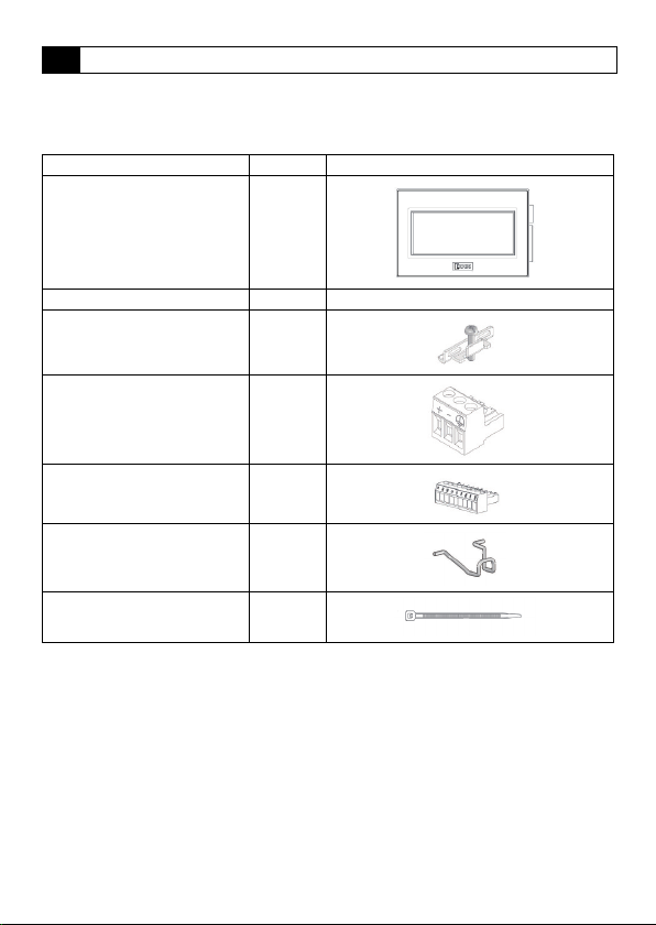
1 Packing
Before installing the Touch, make sure that the specifications of the product conform to
your requirements, and that no parts are missing or damaged due to accidents during
transportation.
Name Pcs/pack
Touch Unit 1
Instruction Sheet [This manual] 1
Mounting clips 2
Power plug
(Attached to the Touch)
Communication I/F plug
(Attached to the Touch)
USB Cable Lock Pin 2
USB Clamp Band 2
1
1
6
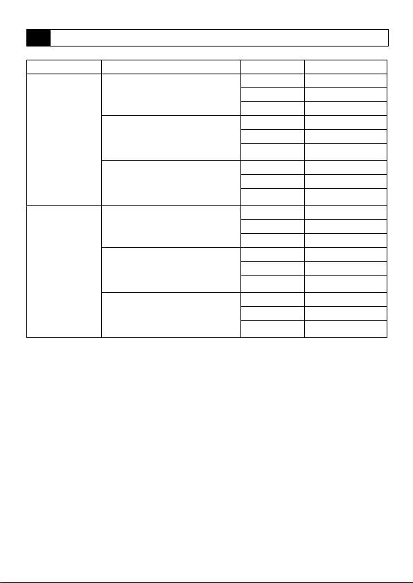
2 Typ e N um ber
LCD size I/O configuration Bezel color Type No.
Light gray FT1A-M12RA-W
Dark gray FT1A-M12RA-B
Silver FT1A-M12RA-S
Light gray FT1A-M14KA-W
Dark gray FT1A-M14KA-B
Silver FT1A-M14KA-S
Light gray FT1A-M14SA-W
Dark gray FT1A-M14SA-B
Silver FT1A-M14SA-S
Light gray FT1A-C12RA-W
Dark gray FT1A-C12RA-B
Silver FT1A-C12RA-S
Light gray FT1A-C14KA-W
Dark gray FT1A-C14KA-B
Silver FT1A-C14KA-S
Light gray FT1A-C14SA-W
Dark gray FT1A-C14SA-B
Silver FT1A-C14SA-S
3.7inch STN
Monochrome LCD
3.8inch TFT Color
LCD
Digital sink in : 6pt
Shared digital sink in / Analog in : 2pt
Relay out : 4pt
Digital source in : 6pt
Shared digital sink in / Analog in : 2pt
Transisitor sink out : 4pt
Analog out : 2pt
Digital sink in : 6pt
Shared digital sink in / Analog in : 2pt
Transisitor source out : 4pt
Analog out : 2pt
Digital sink in : 6pt
Shared digital sink in / Analog in : 2pt
Relay out : 4pt
Digital source in : 6pt
Shared digital sink in / Analog in : 2pt
Transisitor sink out : 4pt
Analog out : 2pt
Digital sink in : 6pt
Shared digital sink in / Analog in : 2pt
Transisitor source out : 4pt
Analog out : 2pt
7
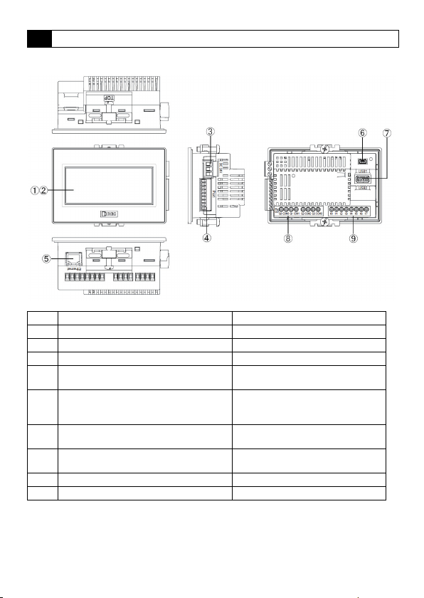
3 Part Names
■ FT1A-*12RA
No. Name Description
(1) Display
(2) Touch Panel
(3) Power Supply Terminal
(4) Serial Interface (Po rt)
(5) Ethernet Interface (Ethernet)
(6) USB Interface (USB 1)
(7) USB Interface (USB 2)
(8) Output Terminal (Q0 to Q3) Relay output (10A)
(9) Input Terminal (I0 to I7) Digital input, Analog input
RS232C, RS422/485
Connector : Terminal Block 9 pin
IEEE802.3u
10BASE-T/100BASE-TX
Connector : RJ-45
USB2.0 (Device)
Connector : Mini-B
USB1.1 (External device)
Connector: TypeA
8
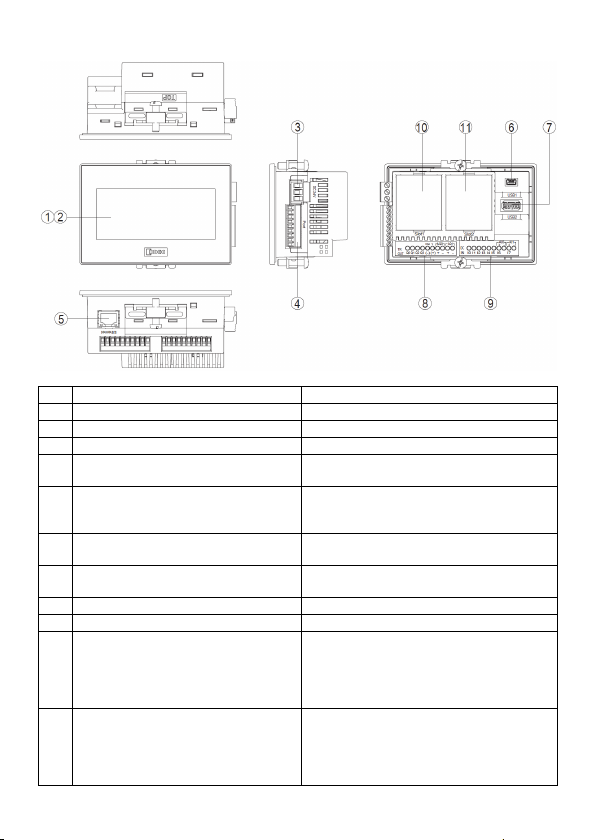
■ FT1A-*14KA/14SA
No. Name Description
(1) Display
(2) Touch Panel
(3) Power Supply Terminal
(4) Serial Interface (Port)
(5) Ethernet Interface (Ethernet)
(6) USB Interface (USB1)
(7) USB Interface (USB2)
(8) Output Terminal (Q0 to Q3, AQ0 to AQ1) Transistor output, analog output
(9) Input Terminal (I0 to I7) Digital input, Analog input
(10) Slot 1
(11) Slot 2
RS232C, RS422/485
Connector : Terminal Block 9 pin
IEEE802.3u
10BASE-T/100BASE-TX
Connector : RJ-45
USB2.0 (Device)
Connector : Mini-B
USB1.1 (External device)
Connector : Type A
Optional product (analog cartridge) expansion
FC6A-PJ2A
FC6A-PK2AV
FC6A-PK2AW
FC6A-PJ2CP
Optional product (analog cartridge) expansion
FC6A-PJ2A
FC6A-PK2AV
FC6A-PK2AW
FC6A-PJ2CP
9
4 External Interfaces
● Make sure to turn off the power to the Touch before wiring each interface.
● Always use ferrules when wiring stranded wire and multiple wires to the terminal block.
Otherwise there is a risk of wires becoming disconnected.
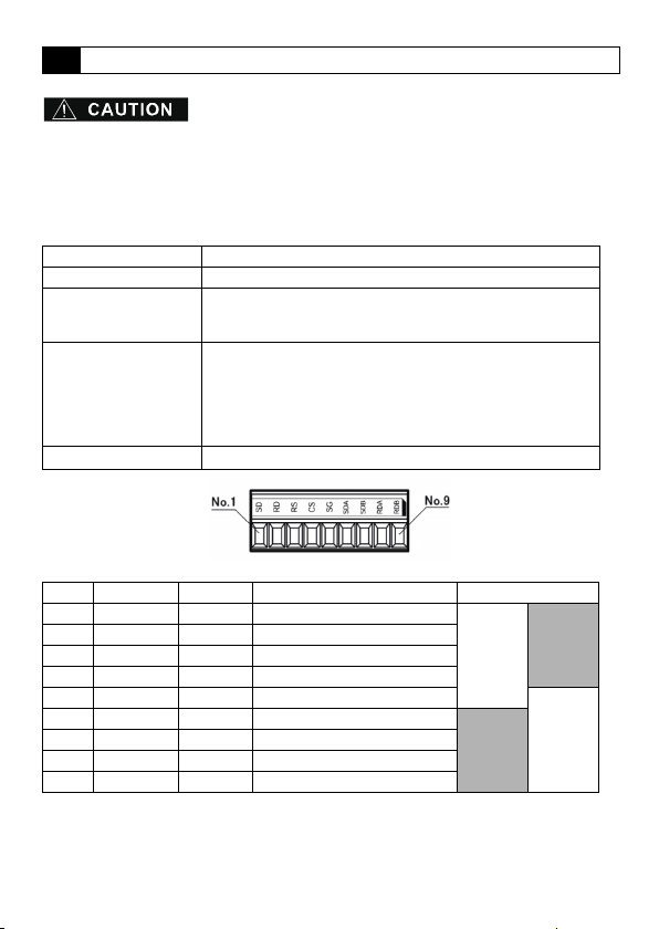
4.1 Serial Interface (Port)
Interface Specification RS232C, RS422/485
Connector Detachable Terminal Block 9 pin
Applicable cable
Recommended ferrule
Tightening Torque
No. Name I/O Function Communication type
1 SD OUT Send Data
2 RD IN Receive Data
3 RS OUT Request to Send
4 CS IN Clear to Send
5 SG - Signal Ground
6 SDA OUT Send Data (+)
7 SDB OUT Send Data (-)
8 RDA IN Receive Data (+)
9 RDB IN Receive Data (-)
<Note>
The Touch is not equipped with terminating resistance. When using the RS422/485
interface, insert terminating resistance with the appropriate value (around 100 to 120 )
between terminal No. 8 (RDA) and terminal No. 9 (RDB) as required.
RS232C: AWG16 to AWG28
RS422/485: AWG16 to AWG28 Shielded twisted-pair
Stripped wire length 7 mm (Solid wire)
AI 0.34-8 TQ (For AWG22)
AI 0.5-8 WH (For AWG20)
AI 0.75-8 GY (For AWG18)
AI 1-8 RD (For AWG18)
AI 1.5-8 BK (For AWG16)
(Phoenix Contact)
0.25 N ·
m
RS232C
10
RS422/485
4.2 I/O Terminals
■ FT1A-*12RA
Applicable cable
Recommended ferrule
AWG16 to AWG22
Stripped wire length 6.5 mm, coating diameter 3.4 mm or lower (Solid wire)
AI 0.34-8 TQ (For AWG22, For 1 wire)
AI 0.5-8 WH (For AWG20, For 1 wire)
AI 0.75-8 GY (For AWG18, For 1 wire)
AI 1-10 RD (For AWG18, For 1 wire)
AI 1.5-10 BK (For AWG16, For 1 wire)
AI TWIN 2 x 0.75 10GY (For AWG18, For 2 wires)
(Phoenix Contact)
Tightening Torque 0.5 to 0.6 N•m (Screwdriver SZS 0.6 x 3.5, Phoenix Contact)
■ FT1A-*14KA/14SA
Applicable cable
Recommended ferrule
AWG20 to AWG22
Stripped wire length 5 mm, coating diameter 2.6 mm or lower (Solid wire)
AI 0.34-8 TQ (For AWG22, For 1 wire)
AI 0.5-8 WH (For AWG20, For 1 wire)
AI-TWIN2 x 0.5-8 WH (For AWG20, For 2 wires)
(Phoenix Contact)
Tightening Torque 0.2 N•m (Screwdriver SZS 0.4 x 2.5, Phoenix Contact)
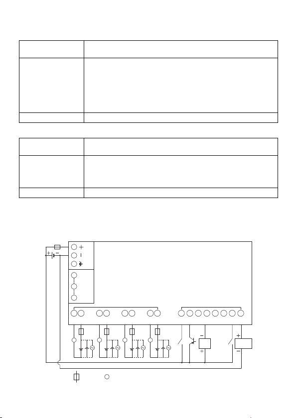
● Terminal Arrangement
• Terminal Arrangement and I/O Wiring Diagrams
■ FT1A-*12RA
Power supply terminal
1 SD
5 SG
Port
9 RDB
Q0 COM0 Q0 COM0 Q0COM0 Q0COM0
Ry OUT
DC IN
I0 I1 I2 I3 I4 I5 I6 I7
L L L L
:
Fuse
:
Load
L
2-wire
Sensor
Analog voltage
output device
11
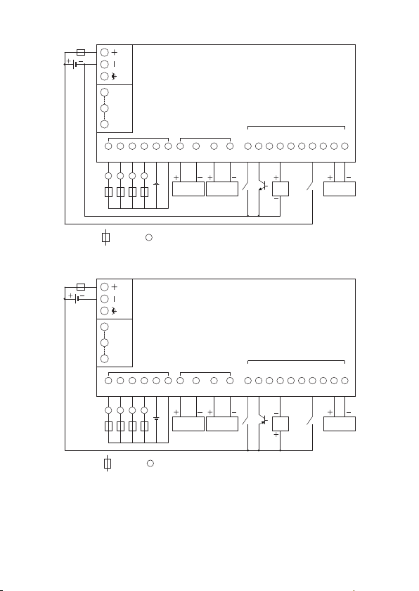
■ FT1A-*14KA
L
: Fuse : Load
Power supply terminal
Q0
LQ1LQ2L
Q3
L
COM
(-)
V
(+)
Tr. OUT Analog OUT
AQ0
(+)
AQ0
(-)
Analog voltage/
current input device
AQ1
(+)
AQ1
(-)
Analog voltage/
current input device
9 RDB
5 SG
1 SD
Port
AI0
(+)
AI0
(-)
AI1
(+)
AI1
(-)
Analog voltage/
current input device
I6 I7
I1 I2 I3 I4 I5I0
2-wire
Sensor
DC IN
■ FT1A-*14SA
Q0
LQ1LQ2L
Power supply terminal
1 SD
5 SG
Port
9 RDB
Tr. OUT Analog OUT
COM
V
Q3
(+)
(-)
L
: Fuse : Load
L
AQ0
AQ0
(+)
(-)
Analog voltage/
current input device
AQ1
AQ1
(+)
(-)
Analog voltage/
current input device
I1 I2 I3 I4 I5I0
2-wire
Sensor
DC IN
AI0
AI0
(+)
(-)
I6 I7
AI1
AI1
(+)
(-)
Analog voltage/
current input device
12
 Loading...