


FL1E
Table of contents
 Loading...
B-1090(6)

Revision History
Date Manual No. Description
November, 2008 B-1090(0)
First print
December, 2008 B-1090(1)
Sensor connections for IDEC SmartRelay:
FL1E-H12RCA / FL1E-B12RCA /
FL1E-H12RCE / FL1E-B12RCE / FL1E-H12SND
February, 2009 B-1090(2)
• Compatibility (FL1C-PM3 memory cartridge in FL1E)
• Compatibility (FL1E-PM4 memory cartridge in old er
IDEC SmartRelay modules)
July, 2009 B-1090(3) Deleting the circuit program and password “Note”
September, 2009 B-1090(4)
• 1. The analog output module (FL1D-K2BM 2) stru c ture
• 1. How to identify the IDEC SmartRelay
(Analog output module)
• 2.1.2 Setup with different voltage classes
• 2.1.3 Compatibility (FL1D-K2BM2)
• 2.2.3 Mounting the Text Display
• 2.3.4 Connecting outputs, Output Internal Circuit
(FL1D-K2BM2)
• 3.6.5 Password
• 3.6.5 Changi ng IDEC SmartRelay from RUN to STOP
mode from the Text Display
• 4.4.20 Analog amplifier (Analog output)
• 6. Compatibility (FL1C-PM3 memory cartridge in FL1E)
• 6. Compatibility (FL1E-PM4 memory cartridge in olde r
IDEC SmartRelay modules)
• A.1 General technical data (Degree of protection)
• A.11 T echnical data: FL1D-K2BM2
• E: Type Number (FL1D-K2BM2)
July, 2010 B-1090(5)
• 1. How to identify the IDEC SmartRelay
(Base module)
• 4.4.11 Seven-day time switch
• 4.4.12 Twelve-month time switch
• A.4 Technical data: FL1E-H12SND
(Backup of the real-time clock at 25°C,
Accuracy of the real-time clock)
• E: Type Number (FL1E-H12SND)
December, 2011 B-1090(6)
• 7. IDEC SmartRelay software
Adding Windows 7 to the supporting OS.
• Deleting the description for LONWORKS.

IDEC SmartRelay Manual i
Safety guidelines
This manual contains notices you have to observe in order
to ensure your personal safety, as well as to prevent damage
to property. The notices referring to your personal safety are
highlighted in the manual by a safety alert symbol, notices
referring to property damage only have no safety alert
symbol. The notices shown below are graded according to
the degree of danger.
If more than one degree of danger is present, the warning
notice representing the highest degree of danger will be used.
A notice warning of injury to persons with a safety alert symbol
may also include a warning relating to property damage.
!
Danger
indicates that death or severe personal injury will result if proper
precautions are not taken.
!
Warning
indicates that death or severe personal injury may result if proper
precautions are not taken.
!
Caution
with a safety alert symbol indicates that minor personal injury can
result if proper precautions are not taken.
Caution
without a safety alert symbol indicates that property damage can
result if proper precautions are not taken.
Note
indicates that an unintended result or situation can occur if the cor-
responding notice is not taken into account.

ii IDEC SmartRelay Manual
Qualified Personnel
The device/system may only be set up and used in
conjunction with this documentation. Commissioning and
operation of a device/system may only be performed by
qualified personnel. Within the context of the safety notices
in this documentation qualified persons are defined as
persons who are authorized to commission, ground and
label devices, systems and circuits in accordance with
established safety practices and standards.
Prescribed Usage
Note the following:
Copyright IDEC CORPORATION All rights reserved
The reproduction, distribution or use of this document or its
contents is not permitted without express written authority.
Offenders will be liable for damages. All rights reserved, in
particular in the event of patents being granted or the
registration of a utility model or design.
Disclaim of Liability
We have reviewed the contents of this publication to ensure
consistency with the hardware and software described.
Since variance cannot be precluded entirely, we cannot
guarantee full consistency. However, the information in this
publication is reviewed regularly and any necessary
corrections are included in subsequent editions.
!
Warning
This device and its components may only be used for the
applications described in the catalog or the technical description,
and only in connection with devices or components from other
manufacturers which have been approved or recommended by
IDEC.
Correct, reliable operation of the product requires proper transport,
storage, positioning and assembly as well as careful operation and
maintenance.

Preface
IDEC SmartRelay Manual iii
Preface
Dear customer
We thank you for purchasing IDEC SmartRelay and
congratulate you on your decision. With IDEC SmartRelay
you have acquired a logic module that meets the stringent
quality requirements of ISO 9001.
IDEC SmartRelay can be used in many fields of applications.
Due to its high functionality and easy operation, IDEC
SmartRelay offers you the utmost efficiency for almost any
application.
Purpose of this manual
This IDEC SmartRelay manual provides you with information
about the creation of circuit programs, about the installation
and use of FL1E IDEC SmartRelay base modules, the Text
Display and the IDEC SmartRelay expansion modules, and
about their compatibility with the previous FL1A–FL1D
versions (FL1x are the last four characters of the order
number of the base modules and differentiate the device
series).
IDEC SmartRelay’s place in information technology
The wiring information in your IDEC SmartRelay manual is
also found in the IDEC SmartRelay Product Info included
with all devices. For further information on programming the
IDEC SmartRelay on your PC, refer to the Online Help for
WindLGC.
WindLGC is the programming software for PCs. It runs
under Windows
. It helps you to get started with IDEC
SmartRelay and to write, test, print out and archive your
programs, independent of the IDEC SmartRelay.
Guide
The manual is divided into 8 chapters:
• Getting started with IDEC SmartRelay
• IDEC SmartRelay installation and wiring
• Programming IDEC SmartRelay
• IDEC SmartRelay functions
• Configuring IDEC SmartRelay
• IDEC SmartRelay memory and battery cartridges
• IDEC SmartRelay software
• Applications

Preface
iv IDEC SmartRelay Manual
Valid range of this manual
The manual applies to devices of series FL1E.
New features of the FL1E IDEC SmartRelay device series
• The Text Display provides an additional display device for
messages, and contains four cursor keys and four functions
keys that can be used in the circuit program.
• An additional password protection function is available in
the Text Display (version 4 or later) and can only be enabled
when the Text Display is used together with IDEC
SmartRelay Base modules (version 4 or later).
• The new IDEC SmartRelay Battery cartridge and the
IDEC SmartRelay Combined Memory/Battery cartridge
provide up to two years of backup time for the real-time
clock. The new IDEC SmartRelay Memory cartridge and
the Combined Memory/Battery cartridge provide 32
Kbytes memory space.
• Additional optional analog inputs and fast digital inputs are
available on some of the FL1E IDEC SmartRelay base
modules.
• FL1E IDEC SmartRelay configuration menus can be
displayed in ten supported languages. You have a
configuration choice to specify the language for IDEC
SmartRelay menus.
• New instruction blocks are available: Pulse Width Modulator
(PWM), Analog Math, and Analog Math Error Detection.
• Message texts can tick on and off the display; can include
bar graphs, can switch between two character sets, and
can be displayed on either the IDEC SmartRelay Display,
the Text Display, or both. Full editing capabilities are
available from WindLGC; editing from the IDEC
SmartRelay base module is limited to simple text. See
section
2.1.3 for further details.
• USB PC cable between a PC and IDEC SmartRelay base
module is available as an option.
• You can now have up to 200 program blocks in your
circuit program.

Preface
IDEC SmartRelay Manual v
Additional differences compared to previous devices
(FL1A to FL1D)
• Extended set of reference parameters for function blocks.
• Enhancements to up/down counter, Operating hours
counter, Twelve-month time switch and analog watchdog
instruction blocks.
• You can find information on compatibility of IDEC Smart-
Relay FL1E to previous devices at section 2.1.3.
Additional support
At our Internet address
http://smart.idec.com/
you can quickly and easily find answers to your queries
about IDEC SmartRelay.

Preface
vi IDEC SmartRelay Manual

IDEC SmartRelay Manual vii
Contents
Preface..................................................................... iii
Contents ................................................................. vii
1 Getting started with IDEC SmartRelay................... 1
2 IDEC SmartRelay installation and wiring ............ 17
2.1 Modular IDEC SmartRelay setup ................................................... 20
2.1.1 Maximum setup ............................................................................. 20
2.1.2 Setup with different voltage classes .............................................. 22
2.1.3 Compatibility .................................................................................. 24
2.2 Installing/removing IDEC SmartRelay........................................... 25
2.2.1 DIN rail mounting........................................................................... 26
2.2.2 Wall-mounting................................................................................ 29
2.2.3 Mounting the Text Display ............................................................. 30
2.3 Wiring IDEC SmartRelay ................................................................ 32
2.3.1 Connecting the power supply ........................................................ 33
2.3.2 Connecting the Text Display power supply....................................34
2.3.3 Connecting IDEC SmartRelay inputs............................................. 35
2.3.4 Connecting outputs........................................................................ 44
2.3.5 Connecting the AS interface bus...................................................49
2.4 Putting into operation..................................................................... 51
2.4.1 Switching on the IDEC SmartRelay/Power On ..............................51
2.4.2 Operating states ............................................................................ 54
3 Programming IDEC SmartRelay .......................... 57
3.1 Connectors ...................................................................................... 58
3.2 Blocks and block numbers ............................................................ 60
3.3 From circuit diagram to IDEC SmartRelay program .................... 63
3.4 The four golden rules for operating IDEC SmartRelay................ 66

viii IDEC SmartRelay Manual
3.5 Overview of IDEC SmartRelay menus .......................................... 68
3.6 Writing and starting the circuit program ...................................... 69
3.6.1 Selecting programming mode ....................................................... 69
3.6.2 The first circuit program................................................................. 70
3.6.3 Circuit program input ..................................................................... 72
3.6.4 Assigning a circuit program name ................................................. 77
3.6.5 Password....................................................................................... 78
3.6.6 Switching IDEC SmartRelay to RUN mode................................... 84
3.6.7 Second circuit program ................................................................. 86
3.6.8 Deleting a block............................................................................. 92
3.6.9 Deleting block groups.................................................................... 93
3.6.10 Correcting programming errors ..................................................... 94
3.6.11 Selecting analog output values for RUN/STOP transition ............. 94
3.6.12 Defining the type of analog outputs............................................... 95
3.6.13 Deleting the circuit program and password ................................... 96
3.6.14 Summertime/wintertime conversion .............................................. 97
3.6.15 Synchronization........................................................................... 101
3.7 Memory space and circuit program size .................................... 103
4 IDEC SmartRelay functions ................................109
4.1 Constants and connectors - Co................................................... 110
4.2 Basic functions list - GF............................................................... 114
4.2.1 AND..............................................................................................115
4.2.2 AND with Edge Detection.............................................................116
4.2.3 NAND (not AND) .........................................................................116
4.2.4 NAND with Edge Detection ..........................................................117
4.2.5 OR ................................................................................................118
4.2.6 NOR (not OR)..............................................................................119
4.2.7 XOR (exclusive OR) .................................................................... 120
4.2.8 NOT (Negation, Inverter)............................................................. 120
4.3 Special functions.......................................................................... 121
4.3.1 Designation of the inputs............................................................. 121
4.3.2 Time response............................................................................. 122

IDEC SmartRelay Manual ix
4.3.3 Backup of the real-time clock ...................................................... 123
4.3.4 Retentivity.................................................................................... 123
4.3.5 Parameter protection ................................................................... 124
4.3.6 Calculating the gain and offset of analog values ......................... 125
4.4 Special functions list - SF ............................................................ 128
4.4.1 On-delay ...................................................................................... 131
4.4.2 Off-delay ...................................................................................... 135
4.4.3 On-/Off-delay ...............................................................................136
4.4.4 Retentive on-delay....................................................................... 138
4.4.5 Interval time-delay relay/Pulse output .........................................139
4.4.6 Edge-triggered interval time-delay relay ...................................... 140
4.4.7 Asynchronous pulse generator.................................................... 142
4.4.8 Random generator....................................................................... 144
4.4.9 Stairwell Light Switch ................................................................... 146
4.4.10 Dual-function switch .................................................................... 148
4.4.11 Seven-day time switch................................................................. 150
4.4.12 Twelve-month time switch ........................................................... 155
4.4.13 Up/down counter ......................................................................... 161
4.4.14 Operating hours counter .............................................................. 164
4.4.15 Frequency trigger ........................................................................ 168
4.4.16 Analog trigger ..............................................................................171
4.4.17 Analog differential trigger............................................................. 174
4.4.18 Analog comparator ...................................................................... 177
4.4.19 Analog watchdog......................................................................... 182
4.4.20 Analog amplifier........................................................................... 185
4.4.21 Latching relay ..............................................................................190
4.4.22 Current impulse relay ................................................................. 191
4.4.23 Message texts.............................................................................. 193
4.4.24 Softkey......................................................................................... 205
4.4.25 Shift register................................................................................. 208
4.4.26 Analog Multiplexer....................................................................... 210
4.4.27 Analog Ramp Control .................................................................. 212
4.4.28 PI controller ................................................................................. 216
4.4.29 Pulse Width Modulator (PWM) ....................................................222

x IDEC SmartRelay Manual
4.4.30 Analog math ................................................................................ 225
4.4.31 Analog math error detection........................................................ 230
5 Configuring IDEC SmartRelay ............................233
5.1 Selecting parameter assignment mode ...................................... 234
5.1.1 Parameters.................................................................................. 235
5.1.2 Selecting the parameters............................................................. 236
5.1.3 Modifying parameters.................................................................. 237
5.2 Setting the default values for IDEC SmartRelay ........................ 239
5.2.1 Setting the time of day and date (FL1E-H12RC...)...................... 240
5.2.2 Setting the display contrast and backlight choice........................ 241
5.2.3 Setting the menu language ......................................................... 243
5.2.4 Setting the number of AIs in the base module ............................ 244
5.2.5 Setting the start screen................................................................ 245
6 IDEC SmartRelay memory
and battery cartridge (card) ................................247
6.1 Security function (CopyProtect).................................................. 250
6.2 Inserting and removing memory and battery cartridges .......... 252
6.3 Copying data from IDEC SmartRelay
to the memory cartridge............................................................... 254
6.4 Copying data from the memory cartridge
to IDEC SmartRelay ...................................................................... 256
7 IDEC SmartRelay software..................................259
7.1 Connecting IDEC SmartRelay to a PC ........................................ 261
8 Applications .........................................................263
8.1 Stairway or corridor lighting........................................................ 265
8.1.1 Requirements for a stairway lighting system............................... 265
8.1.2 Previous solution ......................................................................... 265
8.1.3 Lighting system with IDEC SmartRelay....................................... 266

IDEC SmartRelay Manual xi
8.1.4 Special features and expansion options ...................................... 268
8.2 Automatic door ............................................................................. 269
8.2.1 Requirements of an automatic door............................................. 269
8.2.2 Conventional solution .................................................................. 270
8.2.3 Door control system with IDEC SmartRelay................................ 270
8.2.4 Special features and expansion options ...................................... 273
8.2.5 Extended solution with FL1E-H12RCC ....................................... 273
8.3 Air-conditioning system............................................................... 276
8.3.1 Requirements for an air-conditioning system .............................. 276
8.3.2 Advantages of using IDEC SmartRelay....................................... 279
8.4 Factory door.................................................................................. 281
8.4.1 Requirements for a gate control system......................................281
8.4.2 Previous solution ......................................................................... 282
8.4.3 Extended IDEC SmartRelay solution........................................... 284
8.5 Centralized control and monitoring of several factory doors... 285
8.5.1 Requirements for a gate control system......................................286
8.6 Luminous rows ............................................................................. 289
8.6.1 Requirements for a lighting system .............................................289
8.6.2 Previous solution ......................................................................... 290
8.6.3 Luminous row control system with FL1E-H12RCC...................... 291
8.7 Service water pump...................................................................... 293
8.7.1 Requirements for a control system of a service water pump....... 294
8.7.2 Previous solution ......................................................................... 294
8.7.3 Service water pump system with FL1E-H12RCC........................ 295
8.7.4 Special features and expansions ................................................. 296
A Technical data...................................................... 297
A.1 General technical data.................................................................. 297
A.2 Technical data: FL1E-H12RCC/FL1E-B12RCC ........................... 299
A.3 Technical data: FL1B-M08C2R2 .................................................. 302
A.4 Technical data: FL1E-H12SND..................................................... 305

xii IDEC SmartRelay Manual
A.5 Technical data: FL1B-M08B1S2 ................................................. 307
A.6 Technical data: FL1E-H12RCA/FL1E-B12RCA ........................... 309
A.7 Technical data: FL1B-M08D2R2 .................................................. 312
A.8 Technical data: FL1E-H12RCE/
FL1E-B12RCE and FL1B-M08B2R2 ............................................. 314
A.9 Switching capacity and service life of the relay outputs .......... 317
A.10 Technical data: FL1B-J2B2 .......................................................... 318
A.11 Technical data: FL1D-K2B2, FL1D-K2BM2 ................................. 319
A.12 Technical data: Text Display ....................................................... 320
B Determining the cycle time .................................321
C IDEC SmartRelay without display .....................325
D IDEC SmartRelay menu structure ......................329
D.1 IDEC SmartRelay base module ................................................... 329
D.2 Text Display................................................................................... 331
E Type Numbers ......................................................333
Index......................................................................335

IDEC SmartRelay Manual 1
1
Getting started with IDEC
SmartRelay
Here’s IDEC SmartRelay
IDEC SmartRelay is a universal logic module made by IDEC
that integrates:
• Controls
• Operator and display panel with background lighting
• Power supply
• Interface for expansion modules
• Interface for a memory cartridge, battery cartridge,
combined memory/battery cartridge, IDEC SmartRelay
PC cable or USB PC cable
• Interface for an optional text display (TD) module
• Pre-configured standard functions, for example, on-and
off-delays, current impulse relay and softkey
•Timers
• Digital and analog memory markers
• Inputs and outputs, according to the device type
What IDEC SmartRelay can do for you
IDEC SmartRelay offers solutions for domestic and
installation engineering applications such as stairway
lighting, external lighting, sun blinds, shutters, shop window
lighting and more; switch cabinet engineering, as well as for
mechanical and apparatus engineering such as gate control
systems, air-conditioning systems, rand ainwater pumps.
IDEC SmartRelay can also be implemented for special
control systems in conservatories or greenhouses, for
control signal processing and, by connecting a
communication module such as an AS-i module, for
distributed local controlling of machines and processes.
Special versions without operator panel and display unit are
available for series production applications in small machine,
apparatus, switching cabinet and installation engineering.

Getting started with IDEC SmartRelay
2 IDEC SmartRelay Manual
Which devices are available?
IDEC SmartRelay Base is available in two voltage classes:
• Class 1 24 V, i.e. 12 V DC, 24 V DC, 24 V AC
• Class 2 > 24 V, i.e. 100...240 V AC/DC
IDEC SmartRelay Base is available in two versions:
• With display: 8 inputs and 4 outputs
• Without display (”IDEC SmartRelay Pure”): 8 inputs and
4 outputs
Each version is integrated into four subunits, is equipped
with an expansion interface and Text Display interface and
provides 39 pre-configured standard and special function
blocks for the creation of your circuit program.
Which expansion modules are available?
• IDEC SmartRelay digital modules are available for
operation with 12 V DC, 24 V AC/DC and 100...240 V AC/
DC, and are equipped with four inputs and four outputs.
• IDEC SmartRelay analog modules are available for
operation with 24 V DC and some with 12 V DC,
depending on the specific module. Each is equipped with
two analog inputs or two analog outputs.
The digital/analog modules are integrated in two or four
subunits. Each one is equipped with two expansion
interfaces for connecting additional modules.
Which display modules are available?
• IDEC SmartRelay Base with display
• Text Display

Getting started with IDEC SmartRelay
IDEC SmartRelay Manual 3
Features of the Text Display
The Text Display is available with the FL1E series. It
provides an additional display that is wider than the Base
module. It has four function keys that you can program in
your circuit program as inputs. Like the IDEC SmartRelay
Base module, it has four cursor keys, an ESC key and an OK
key that you can also program in your circuit program and
use for navigation on the Text Display.
You can create and download a power-up screen for the
Text Display from WindLGC. This screen displays briefly
when you initially power on the Text Display. You can also
upload the power-up screen from the Text Display to
WindLGC.
The menus for the Text Display are shown in Appendix
section
D.2. You configure the settings for the Text Display
independently from the IDEC SmartRelay Base module. The
settings can be different.
Which communication modules are available?
• IDEC SmartRelay communication module (CM) AS
interface, which is described in more detail in a separate
documentation.
The communication module has four virtual inputs and
outputs, and acts as an interface between an AS-
Interface system and an IDEC SmartRelay system. The
module enables four data bits to be transferred from the
IDEC SmartRelay base module to the AS-Interface
system and vice versa.

Getting started with IDEC SmartRelay
4 IDEC SmartRelay Manual
It’s your choice
The various IDEC SmartRelay Base versions, expansion
modules, Text Display and communication modules offer
you a highly flexible and adaptive system to suit your specific
tasks.
The IDEC SmartRelay system offers you many solutions
such as for small domestic installations, simple automation
tasks, and even complex engineering tasks involving its
integration into a bus system (e.g. communication module
AS interface).
Note
IDEC SmartRelay base module may only be equipped with
expansion modules of the same voltage class. Mechanical
encoding pins in the housing prevent you from connecting devices
of a different voltage class.
Exception: The left-hand interface of an analog module or
communication module is galvanically isolated.
This type of expansion module can therefore be connected to
devices of a different voltage class. See also Chapter 2.1.
A Text Display, if used, can be connected only to an FL1E IDEC
SmartRelay base module.
Each IDEC SmartRelay base module supports the following
connections for the creation of the circuit program, regardless of the
number of connected modules:
• Inputs 11 to I24
• Analog inputs AI1 to AI8
• Outputs Q1 to Q16
• Analog outputs AQ1 and AQ2
• Memory Markers M1 to M27:
- M8: Startup marker
- M25: Backlight flag: IDEC SmartRelay Display
- M26: Backlight flag: Text Display
- M27: Message text character set flag
• Analog Memory Markers AM1 to AM6
• Shift register bits S1 to S8
• 4 cursor keys
• 16 blank outputs X1 to X16
I7 I8
Q1 Q2 Q3 Q4
4
L1 N
09
I5 I6I2 I3 I4I1
72
55
53
1 2 1 2 1 2 1 2
6
IDEC SmartRelay Base
(e.g.: FL1E-H12RCC)
Q4
Q1 Q2
L1 N I2 I3 I4I1
36
09
53
4
Q3
RUN/STOP
53
1 2 1 2
1 2 1 2
IDEC SmartRelay
expansion module
(e.g.: FL1B-M08C2R2)
Getting started with IDEC SmartRelay
IDEC SmartRelay Manual 5
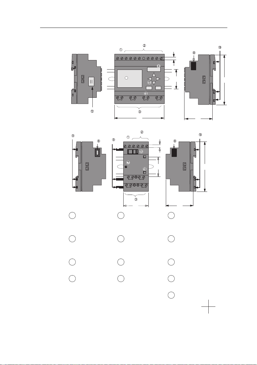
The IDEC SmartRelay structure
Power supply Control panel
(not for FL1E-
B12...)
Mechanical coding
pins
Inputs LCD
(not for FL1E-
B12...)
Mechanical coding
sockets
Outputs RUN/STOP
indicator
Slide
Module slot
with cap
Expansion
interface
Text Display
cable connector
Version number
(example:
represents Version 1.)
1
5
9
2
6
10
3
7
11
4
8
12
13
X 2
3 4
I7 I8
Q1 Q2 Q3 Q4
4
L+ M
4
6
5
09
I5 I6I2 I3 I4I1
72
55
53
1 2 1 2 1 2 1 2
IDEC SmartRelay Base
(e.g.: FL1E-H12RCE)
Q3 Q4
Q1 Q2
L+ M I2 I3 I4I1
09
4
36
53
53
RUN/STOP
1 2 1 2
1 2 1 2
IDEC SmartRelay
expansion module
(e.g.: FL1B-M08B2R2)
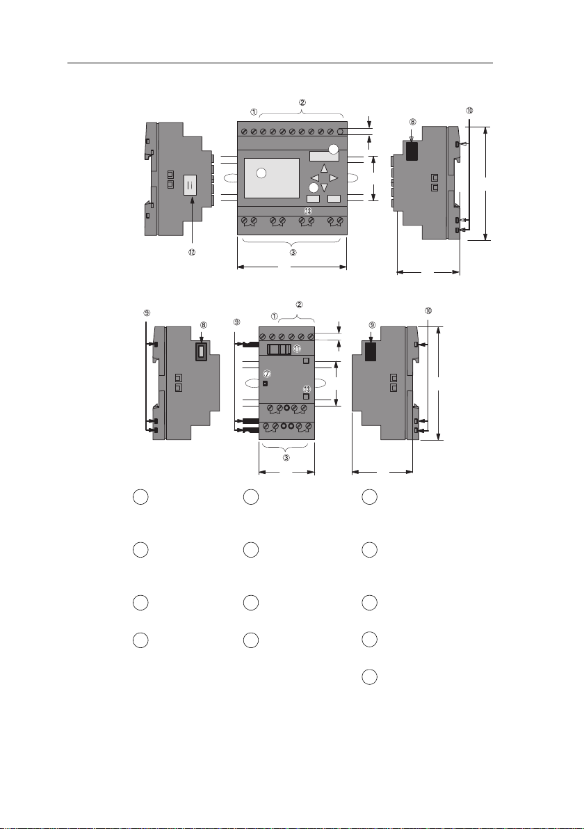
Getting started with IDEC SmartRelay
6 IDEC SmartRelay Manual
Power supply Control panel
(not for FL1E-
B12...)
Mechanical coding
pins
Inputs LCD
(not for FL1E-
B12...)
Mechanical coding
sockets
Outputs RUN/STOP
indicator
Slide
Module slot
with cap
Expansion
interface
Text Display
cable connector
Version number
1
5
9
2
6
10
3
7
11
4
8
12
13
Getting started with IDEC SmartRelay
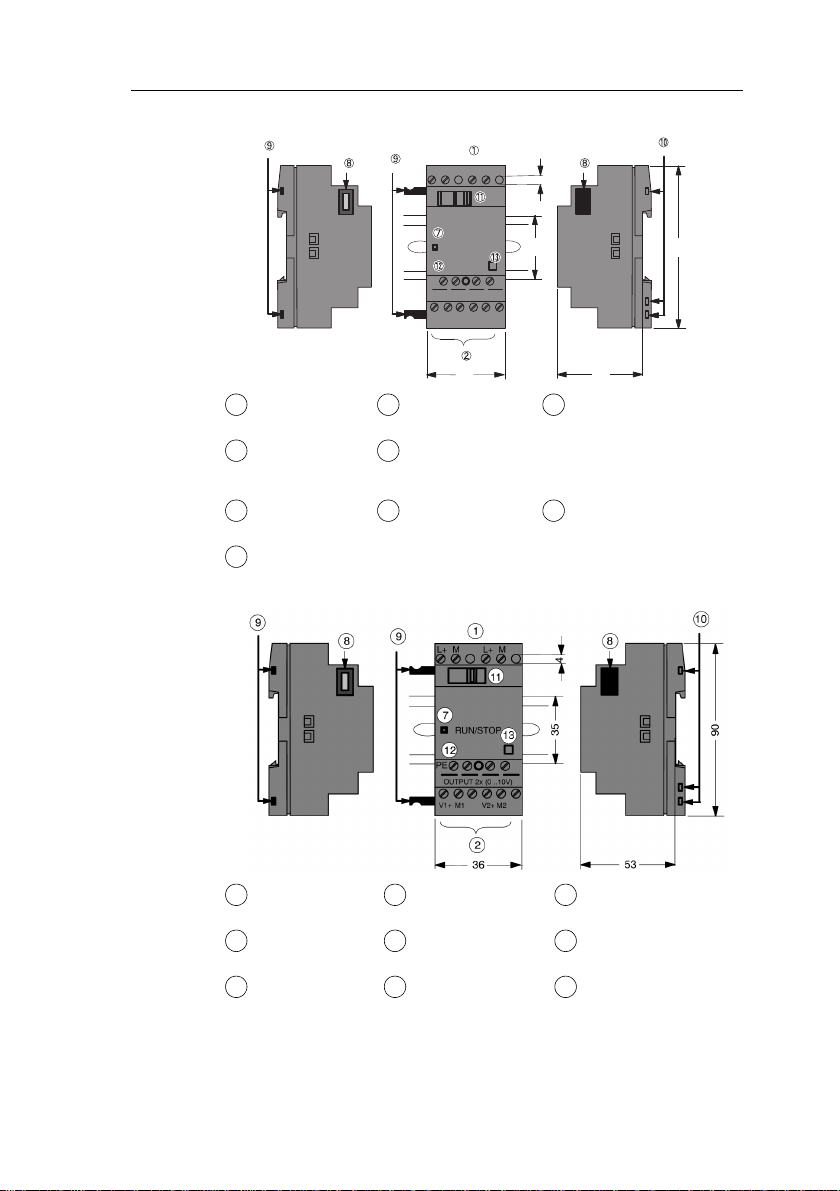
IDEC SmartRelay Manual 7
FL1B-J2B2
I1
PE
INPUT2x(0..10V/0..20mA)
L+ M
09
M1 U1 M2 U2I2
4
L+ M
RUN/STOP
36 53
53
FL1D-K2B2
Power supply Mechanical
coding pins
PE terminal, for
connecting earth and
the shielding of
analog measuring
cables.
Inputs Mechanical
coding sockets
RUN/STOP
indicator
Slide Version number
Expansion interface
Power supply Expansion
interface
Slide
Outputs Mechanical
coding pins
PE terminal, for
connecting earth
Version number
RUN/STOP
indicator
Mechanical
coding sockets
1
9
12
2
10
7
11
13
8
1
8
11
2
9
12
7
10
13
Getting started with IDEC SmartRelay
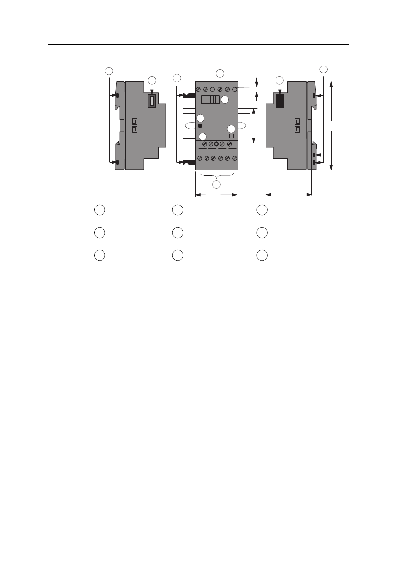
8 IDEC SmartRelay Manual
FL1D-K2BM2
V1+
OUTPUT 2x(0..10V or 0/4..20mA)
L+M
36
RU N / ST O P
1
7
9
9
88
M1
PE
M2V2+
4
L+M
2
11
10
12
53
90
35
13
I2I1
Power supply Expansion
interface
Slide
Outputs Mechanical
coding pins
PE terminal, for
connecting earth
Version number
RUN/STOP
indicator
Mechanical
coding sockets
1
8
11
2
9
12
7
10
13

Getting started with IDEC SmartRelay
IDEC SmartRelay Manual 9
Text Display
Communication interface
Power supply
The Text Display includes a wid
er display area than the
IDEC SmartRelay Display. It includes four programmable
cursor keys, four programmable function keys, and an ESC
and OK key. You use the included Text Display cable to
connect from the communication interface on the right side
of the Text Display to the corresponding interface on the left
side of the IDEC SmartRelay base module.
How to identify the IDEC SmartRelay
The IDEC SmartRelay identifier informs you of various
pr
operties.
Base module
FL1E-
B: Base module without display
H: Base module with display
Number of Inputs and Outputs
R: Relay output S: Tr. (source) output
C: With clock N: Without clock
D: 24V DC E: 12/24V DC A: 24V AC/DC
B: 100...240V AC C: 100...240V AC/DC

Getting started with IDEC SmartRelay
10 IDEC SmartRelay Manual
Expansion module
Digital module
FL1B-M
Number of Inputs and Outputs
B1: 24V DC B2: 12/24V DC
C2: 100...240V AC/DC D2: 24V AC/DC
S: Tr. (source) output R: Relay output
Terminal type 2: non-removable terminal
Analog input module
FL1B-J
Number of Inputs
Resolution B: 10bit
Terminal type 2: non-removable terminal
Analog output module
FL1D-K
Number of Outputs
Resolution B: 10bit
blank: 0 ... 10V M: 0 ... 10V, 0/4 ... 20 mA
Terminal type 2: non-removable terminal
Communication module
FL1B-
C: Communication module
AS: AS-Interface
blank: AS-Interface rated voltage (30V DC) C1: 24V AC/
DC
Terminal type 2: non-removable terminal
Text Display
FL1E-
RD: Remote Display
Version type
Getting started with IDEC SmartRelay
IDEC SmartRelay Manual 11
Symbols
Version with display unit is equipped with 8 inputs and 4 outputs
Version without display unit is equipped with 8 inputs and 4 outputs
The digital module is equipped with 4 digital inputs and 4 digital
outputs
The analog module is equipped with 2 analog inputs or two analog
outputs, according to the device type
The communication module (CM); for example, AS Interface is
equipped with 4 virtual inputs and 4 virtual outputs
The Text Display
Getting started with IDEC SmartRelay
12 IDEC SmartRelay Manual
Versions
The following IDEC SmartRelay versions are available:
(1): Of those can be used alternatively: 4 analog inputs (0 ... 10V) and 4 fast inputs.
(2): AC versions: Two groups consisting of 4 inputs each. Each input within a group
must be connected to the same phase. It is possible to interconnect groups with
a different phase.
(3): The digital inputs can be operated with P or N action.
Symbol Designation Supply
voltage
Inputs Outputs Properties
FL1E-H12RCE 12/24 V DC 8 digital
(1)
4 relays
(10 A)
FL1E-H12SND 24 V DC 8 digital
(1)
4 solid state
24V / 0.3A
no clock
FL1E-H12RCA
(3)
24 V AC/
24 V DC
8 digital 4 relays
(10A)
FL1E-H12RCC
(2)
100...240 V
AC/DC
8 digital 4 relays
(10A)
FL1E-B12RCE 12/24 V DC 8 digital
(1)
4 relays
(10A)
no display unit
no keyboard
FL1E-B12RCA
(3)
24 V AC /
24 V DC
8 digital 4 relays
(10A)
no display unit
no keyboard
FL1E-B12RCC
(2)
100...240 V
AC/DC
8 digital 4 relays
(10A)
no display unit
no keyboard
Getting started with IDEC SmartRelay
IDEC SmartRelay Manual 13
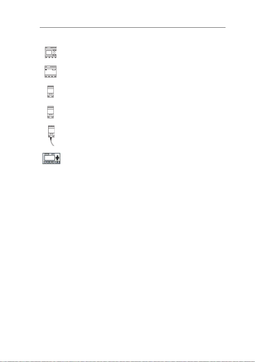
Expansion modules
The following expansion modules can be connected to IDEC
SmartRelay:
(1): Different phases are not allowed within the inputs.
(2): 0 ... 10 V, 0 ... 20 mA can be connected optionally.
(3): Digital inputs can be operated either with P or with N action.
(4): 0 ... 10 V, 0/4 ... 20 mA can be connected optionally.
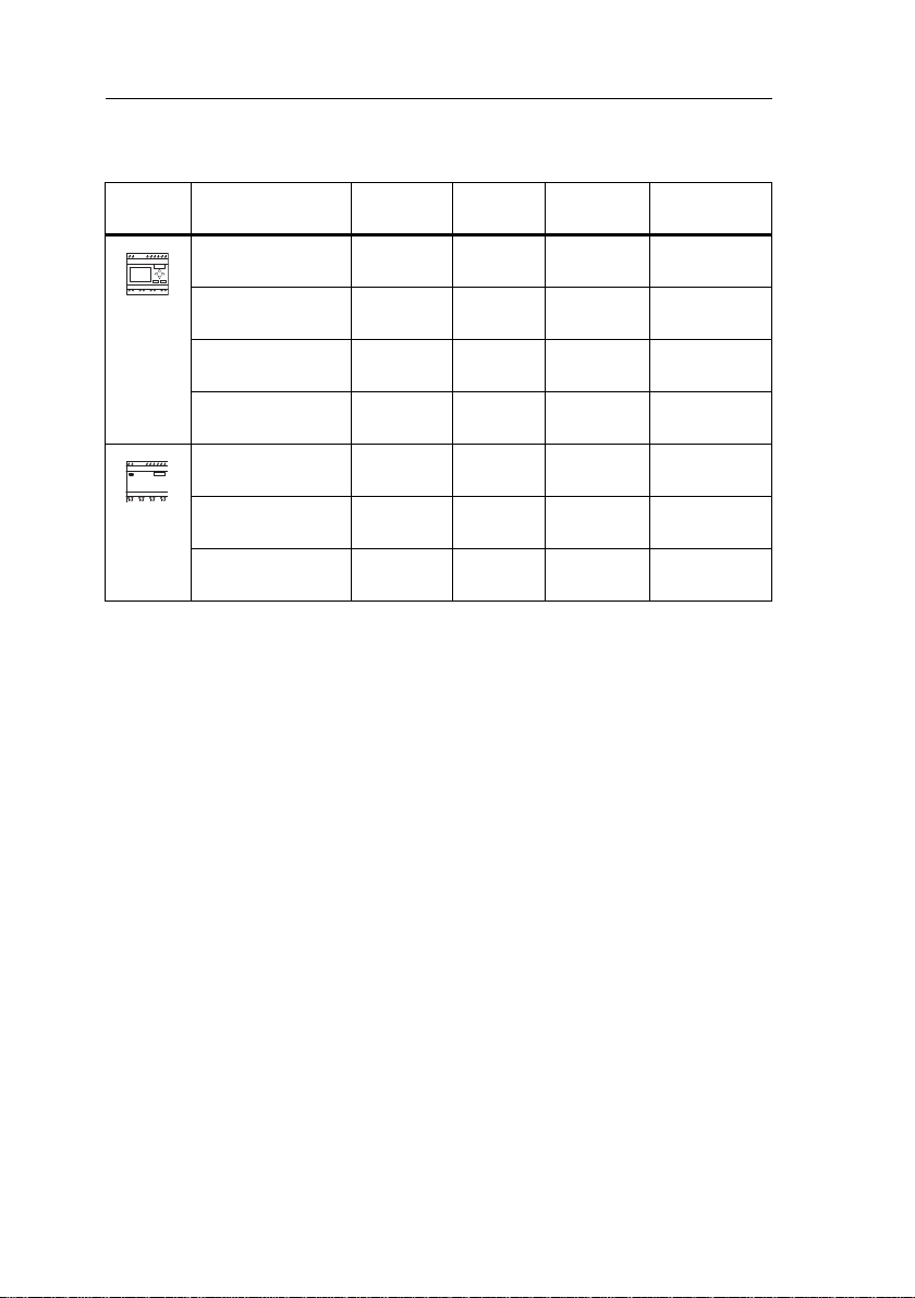
Communication modules
The following communication modules can be connected
t
o IDEC SmartRelay:
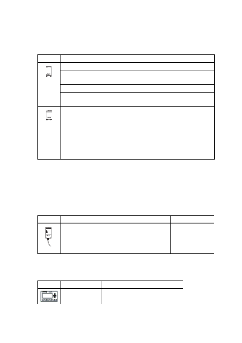
Text Display Module
The following Text Display module is
available:
Symbol Name Power supply Inputs Outputs
FL1B-M08B2R2 12/24 V DC 4 digital 4 relays (5A)
FL1B-M0
8B1S2 24 V DC 4 digital 4 solid state 24V
/ 0.3A
FL1B-M08D2R2
(3)
24 V AC/DC 4 digital 4 relays (5A)
FL1B-M08C2R2 100...240 V
AC/DC
4 digital
(1)
4 relays (5A)
FL1B-J2B2 12/24 V DC 2 analog
0 ... 10V or
0 ... 20mA
(2)
none
FL1D-K2B2 24 V DC none 2 analog
0 ... 10 V DC
FL1D-K2BM2 24 V DC none 2 analog
0 ... 10 V DC,
0/4 ... 20 mA
(4)
Symbol Name Power supply Inputs Outputs
IDEC Smart-
Rela
y CM AS
Interface
30 V DC the next four inputs
after the physical
inputs of IDEC
SmartRelay
(I
n
... I
n+3
)
the next four
outputs after the
physical outputs of
IDEC SmartRelay
(Q
n
... Q
n+3
)
Symbol Name Supply voltage Display
Text Display 24 V AC/DC
12 V DC
LCD (
128 x 64)
4-row display

Getting started with IDEC SmartRelay
14 IDEC SmartRelay Manual
Certification and approvals
IDEC SmartRelay is certified to cULus and FM.
• cULus Haz. Loc.
Underwriters Laboratories Inc. (UL) to
- UL 508 (Industrial Control Equipment)
- CSA C22.2 No. 142 (Process Control Equipment)
- UL 1604 (Hazardous Location)
- CSA–213 (Hazardous Location)
APPROVED for use in
Class I, Division 2, Group A, B, C, D Tx
Class I, Zone 2, Group IIC Tx
• FM Approval
Factory Mutual Research (FM) to
Approval Standard Class Number 3611, 3600, 3810
APPROVED for use in
Class I, Division 2, Group A, B, C, D Tx
Class I, Zone 2, Group IIC Tx
For further information, see our Internet address
(URL: http://www.idec.com/usen)
Note
You will find current approvals on the rating plate of the relevant
module.
IDEC SmartRelay is issued with the CE Certificate of
Conformity. It is compliant with IEC 60730-1 and IEC 61131-
2 and interference-proof to EN 55011, Limit Class B.
Marine certification has been requested.
• ABS (American Bureau of Shipping)
• BV (Bureau Veritas)
• DNV (Det Norske Veritas)
• GL (Germanischer Lloyd)
• LRS (Lloyds Register of Shipping)
• Class NK (Nippon Kaiji Kyokai)
IDEC SmartRelay modules are therefore suitable for use in
industrial and residential areas. Use in Class I, Division 2,
Group A, B, C and D locations or in non-hazardous locations
is supported.

Getting started with IDEC SmartRelay
IDEC SmartRelay Manual 15
Marine certification requires the surge protective device what
manufactured by DEHN+SÖHNE GmbH+Co., in a case of
12/24V DC or 24V DC power line. The required Type No. and
Part No.: BVT AD 24, 918 402. See Note on page 298.
For further information, see our Internet address
(URL: http://www.idec.com/usen)
✔
ID for Australia
Recycling and Disposal
IDEC SmartRelay units can be fully recycled, due to their
low-
pollutant equipment. Contact a certified electronic waste
disposal center for environmentally acceptable recycling and
disposal of your old devices.
Our products carrying the label shown at the side are compliant
with AS/NZS 2064:1997 (Class A) standard.
!
Warning
Risk of death, personal injury or property damage can occur if you
do not follow safety precautions for hazardous locations.
In potentially explosive atmospheres, do not disconnect
connectors when the system is in RUN. Always switch off the
power supply to IDEC SmartRelay and its components before you
disconnect any connectors or components.
Substitution of components can impair suitability for Class I,
Division 2 locations. Combinations of equipment are subject to
investigation by the local authority having jurisdiction at the time of
installation.

Getting started with IDEC SmartRelay
16 IDEC SmartRelay Manual
Loading...