

Page 1
CONNECTION GUIDE
F
VPN ROUTER
SR-VPN1
Step 1 System Requirements
D Supplied Accessories
• Power adapter ………… 1
• Cushion sheet …………1
• Ferrite EMI filter …………1
• Precautions guide
•
“Setting the interface language and the Time Zone” leaflet
• Connection Guide (This guide)
Read the “PRECAUTIONS” leaflet first, if you have not done so.
Thank you for purchasing this Icom product. The SR-VPN1
vpn router is designed and built with Icom’s IP network
technology. We hope you agree with Icom’s philosophy of
“technology first.” Many hours of research and development went into the design of your SR-VPN1.
D Other requirements
• PC
• Ground wire
• LAN cable
Step 3 Automatic setting data load with a USB flash drive
The setting data or firmware can be automatically loaded
into the SR-VPN1 from a USB flash drive.
It is useful to recover the configuration or to update the
firmware.
• The USB flash drive is not supplied. Purchase separately.
• See the SR-VPN1 instruction manual for details.
Tu rn OFF the SR-VPN1’s power
by disconnecting the power adapter,
and then insert the USB flash
drive securely. Then, turn ON the power again by
connecting the power adapter.
About the USB flash drive
• A USB flash drive such as one with biometric authentication,
or one with password protection is not supported.
• Turn OFF the SR-VPN1's power before inserting or
removing the USB flash drive, to prevent data corruption.
• Either one of the USB slots accepts the USB flash drive, but
insert only one USB flash drive at a time.
• Insert the USB flash drive securely.
• NEVER remove the USB flash drive or turn OFF the
SR-VPN1's power, while transferring data. It will cause data
corruption, or damage the USB flash drive.
• After the firmware updating is finished, check the firmware
version on the setting screen to verify that the update was
correctly done.
• When importing setting data from the USB flash drive to
the SR-VPN1, the originally programmed setting data is
automatically saved as “bakdata.sav” in the USB flash drive,
as a backup.
About this Connection Guide:
This Connection Guide explains the basic operation for the
SR-VPN1. Access our website to download the instruction
manual.
Icom website http://www.icom.co.jp/world/
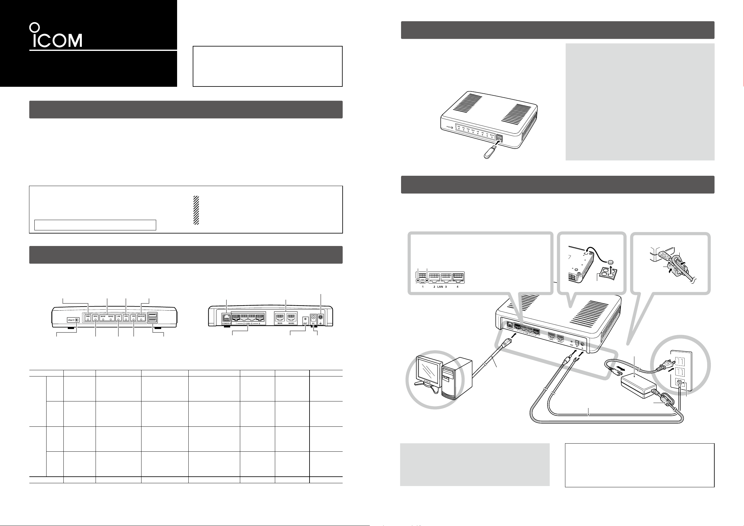
Step 2 Panel description
D About the status indicator
ront Panel
[PWR] LED
<UPDATE> Button
Status PWR MSG WAN (1/2) LAN*1*
Green ON
Lit
Orange Booting
[WAN](1/2)LED
[MSG] LED
A firmware update is
[VPN] LED
[LAN] LED [PPP] LED
(Online Update)
ready
Accessing the USB
flash drive
[BACKUP] LED
[USB] Port
USB2.0
(
(See the precautions guide for more details on the <INIT> and <UPDATE> buttons.)
WAN connected
(1000BASE-T)
WAN connected
(10BASE-T/
100BASE-TX)
)
(More than 1 connection)
(More than 1 connection)
NOTE:
• Adobe® Reader® is required on your PC in order to display the
downloaded instruction manual. (PDF File)
• If your PC does not have Adobe
it from the Adobe® website.
Rear Panel
• The [WAN1] and [WAN2] ports on the setting screen point the
[WAN] and [WAN2] ports on the rear panel.
LAN connected
(1000BASE-T)
LAN connected
[CONSOLE] Port
(RJ-11)
[LAN](1 to 4) Port
(RJ-45)
2
(10BASE-T/
100BASE-TX)
VPN PPP BACKUP
IPsec connected
(More than 1
connection)
— — —
®
Reader®, please download
[WAN](1/2) Port
(RJ-45)
<INIT> Button
PPP connected
(More than 1
connection)
Ground terminal
DC Jack
Backup line is
communicating.
Step 4 Connecting and turning the power ON
Follow the steps q to y to connect the devices.
• When connecting in the factory default condition, the connected network must be disconnected.
• If [LAN] does not light, check the LAN cable and try again.
Verify the LEDs light
y
When the [LAN] LEDs on the rear do not light, verify
that the LAN cable is securely connected.
q w
Status indicator:
Lit: LAN connected
Blinking: LAN data communicating
Green: 1000BASE-T
q
Orange: 10BASE-T/100BASE-TX
w
SR-VPN1
(Default: 192.168.0.1)
To the
[LAN] port
LAN cable*
(Purchase separately)
*Category 5e or higher
Start the PC
PC
t
Connect
e
the cables
To the DC jack
Attach the cushions
q
Ground wire
(Purchase separately)
To the Ground terminal
Cushion Sheet
Attach the ferrite EMI filter
w
Ferrite EMI
filter
Wrap the cable once
around the filter.
Power adapter
Ferrite EMI filter
Power cable
Connect the
r
power supply
The [PWR] LED on the
front panel lights.
AC wall socket
Ground terminal
Green —
Blinking
Not Lit OFF — Not connected Not connected — — —
*1 When 1000BASE-T/10BASE-T/100BASE-TX are mixed, the [LAN] LED lights in orange.
*2 The data communication status for each [LAN] port can be checked with the [LAN] LED on the rear panel.
Orange
Initialization in
progress/
<INIT> button
Green/Orange
(Online Update)
Firmware downloading
—
WAN is communicating
(1000BASE-T)
WAN is communicating
(10BASE-T/
100BASE-TX)
— — — —
— — — —
WARNING!
R
To prevent electrical shock, television interference (TVI),
broadcast interference (BCI) and other problems, ground the
SR-VPN1 through the ground terminal.
NEVER connect the ground terminal to a gas or electric pipe.
This may result in an electrical shock or cause a fire.
IP address for PC
The SR-VPN1’s IP address is set to “192.168.0.1”, and DHCP
server to “Enable” as default. Therefore, set the connecting PC
for the IP address to automatically access.
See the PC’s instruction manual for the IP address setting
details.
Continued on the back side.
Page 2
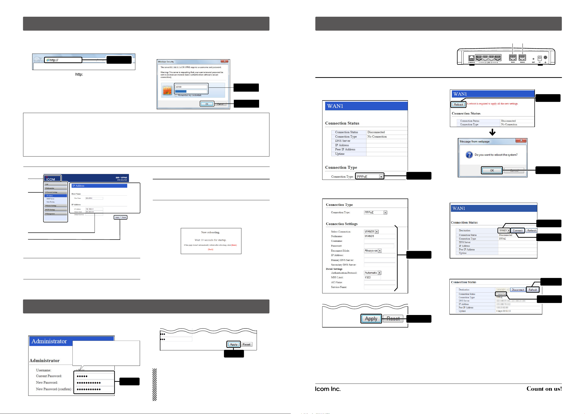
Step 5 Configure the network connection
SR-VPN1 (Rear panel)
Step 7 Using the router function
The following procedures (q to e) describe how to access the SR-VPN1 setting screen using a web browser.
q Open your web browser, then enter the IP address of the
SR-VPN1 into the address bar.
e Enter “admin” (fixed username) and “admin” (default
password) in their respective input fields on the Login
Authentication screen, and then click [OK].
192.168.0.1/
*The default IP address is “ //192.168.0.1/.”
Enter
w Push the [ENTER] key.
• The Login Authentication screen will appear.
• When accessing the web browser for the first time,
the time zone setting is required. See the
“Setting the
••••••••
interface language and the Time Zone” leaflet for details.
To prevent unauthorized access
You must be careful when choosing your password, and change
it occasionally.
See the SR-VPN1 instruction manual for the password setting.
• Choose one that is not easy to guess.
• Use numbers, characters and letters (both lower and upper case).
About web browsers
We have tested the SR-VPN1 with Microsoft Internet Explorer 11.
Activate the JavaScript and set to allow Cookies on your web
browser to correctly display the setting screen.
If
Microsoft Internet Explorer 8 or earlier versions
screen may not be correctly displayed.
About the setting screen
• See the SR-VPN1 instruction manual for details.
e Setting screen
q
Displays the settings and values when you click the screen
name.
w
r Setting buttons
Save or cancel setting values.
If “A reboot is required to apply all the new settings” is displayed on the screen when you click [Apply], click [Reboot].
The SR-VPN1 reboots, and the setting items and values are
updated.
e
r
q Enter
w Click
are used, the
The Router function (Connection Type) is set to “No
Connection” as default.
After connecting the modem for ADSL, VDSL, and CATV,
or the ONU (Optical Network Unit) for the FTTH to the SRVPN1's [WAN1] port (Main line), configure the Connection
Type (DHCP Client/Static IP/PPPoE) based on your network
contractual coverage.
q Click [Router Settings], then click [WAN1].
• The [WAN1] screen is displayed.
w Select [Connection Type]. (Example: PPPoE)
Select
e Configure the [Connection Settings] for the connection
type selected in step w. (Example: PPPoE)
[WAN1] port
(Main line)
[WAN2] port
(Backup line)
t Click [Reboot] to restart the SR-VPN1.
q Click
w Click
y When the SR-VPN1 has restarted, select the connecting
destination, and then click [Connect].
• The destination cannot be selected while connecting.
q Select
w Click
q Link to the Icom web site
Click the Icom logo to open the Icom web site if your PC is
connected to the Internet.
w Setting menu
Displays the screen name list on a menu line. When you
The above message is displayed on the screen while the
SR-VPN1 is rebooting.
• If the SR-VPN1 is still rebooting, clicking [Back] does not return to
the setting screen. Retry when the rebooting is complete.
• Items and buttons may differ, depending on the setting.
click each menu title, a list of items drops down which you
can use to select the desire setting item.
Step 6 Changing the administrator's password
To prevent unauthorized access, you must change the password.
q Click [Management] menu, then [Administrator].
w Fill out each boxes to change the password.
Carefully enter the desired password
of up to 31 characters.
Use numbers, characters and letters
(both lower and upper case).
Enter
e Click [Apply.]
* Enter the new administrator's password from now on.
NOTE: If you have forgotten your password, you cannot
access the SR-VPN1's setting screen.
When you forgot your password:
Hold down the [INIT] button by following the instructions
described in the precautions guide. The SR-VPN1 will
have to be reset as its default.
Click
Configure
u Click [Refresh] to update the configurations.
• If “Connected” is not displayed in the [Connection Status], check
the configurations in step e.
q Click
r Click [Apply.]
Click
ALL RIGHTS RESERVED. This document contains material protected under International and Domestic Copyright Laws and Treaties. Any
unauthorized reprint or use of this material is prohibited. No part of this document may be reproduced or transmitted in any form or by any
means, electronic or mechanical, including photocopying, recording, or by any information storage and retrieval system without express written
permission from Icom Incorporated.
All stated specifications and design are subject to change without notice or obligation.
Adobe and Adobe Reader are registered trademarks of Adobe Systems Incorporated in the United States and/or other countries.
Icom, Icom Inc. and the Icom logo are registered trademarks of Icom Incorporated (Japan) in Japan, the United States, the United Kingdom,
Germany, France, Spain, Russia and/or other countries.
All other products or brands are registered trademarks or trademarks of their respective holders.
1-1-32 Kamiminami, Hirano-ku, Osaka 547-0003, Japan
A-7072W-3EX-q Printed in Japan
© 2013
w Check
-2015 Icom Inc.
 Loading...