


INSTRUCTION MANUAL
VHF MARINE TRANSCEIVER IC-M93D IC-M93D EURO
This device complies with Part 15 of the FCC Rules. Operation is subject to the condition that this device does not cause harmful interference.
Icom Inc.
Thank you for choosing this Icom product. This product is designed and built with Icom's state of the art technology and craftsmanship. With proper care, this product should provide you with years of trouble-free operation.
IMPORTANT
READ ALL INSTRUCTIONS carefully and completely before using the transceiver.
SAVE THIS INSTRUCTION MANUAL—This instruction manual contains important operating instructions for the IC-M93D and IC-M93D EURO.
This instruction manual includes some functions which are usable only when they are preset by your dealer. Ask your dealer for details.
Icom is not responsible for the destruction, damage to, or performance of any Icom or non-Icom equipment, if the malfunction is because of:
- Force majeure, including, but not limited to, fires, earthquakes, storms, floods, lightning, other natural disasters, disturbances, riots, war, or radioactive contamination.
- The use of Icom transceivers with any equipment that is not manufactured or approved by Icom.
EXPLICIT DEFINITIONS
| WORD | DEFINITION |
|---|---|
| ∆DANGER! | Personal death, serious injury or an explosion may occur. |
| Personal injury, fire hazard or electric shock may occur. | |
| CAUTION | Equipment damage may occur. |
| NOTE | If disregarded, inconvenience only. No risk of personal injury, fire or electric shock. |
ABOUT CE AND DOC
Hereby, Icom Inc. declares that the versions of IC-M93D EURO which have the "CE" symbol on the product, comply with the essential requirements of the Radio Equipment Directive, 2014/53/EU, and the restriction of the use of certain hazardous substances in electrical and electronic equipment Directive, 2011/65/EU.
The full text of the EU declaration of conformity is available at the following internet address: https://www.icomjapan.com/support/
IN CASE OF EMERGENCY
If your vessel requires assistance, contact other vessels and the Coast Guard by sending a distress call on Channel 16.
USING CHANNEL 16 DISTRESS CALL PROCEDURE
- 1. "MAYDAY MAYDAY MAYDAY."
- 2. "THIS IS ......" (name of vessel)
- 3. Say your call sign or other indication of the vessel (AND your 9 digit DSC ID, if you have one).
- 4. "LOCATED AT ......" (your position).
- 5. State the nature of the distress and assistance required.
- 6. Give any other information which might facilitate the rescue.
Or, transmit your Distress call using Digital Selective Calling (DSC) on Channel 70.
USING DIGITAL SELECTIVE CALLING (Ch 70) DISTRESS CALL PROCEDURE
- While lifting up the key cover, hold down [DISTRESS] for 3 seconds until you hear 3 short beeps and then one long beep.
-
2. Wait for an acknowledgment on Channel 70 from a coast station.
- After the acknowledgement is received, Channel 16 is automatically selected.
- Hold down [PTT], then transmit the appropriate information as listed to the left.
PRECAUTIONS
▲ DANGER! NEVER short the terminals of the battery pack. Shorting may occur if the terminals touch metal objects such as a key, so be careful when placing the battery packs (or the transceiver) in bags, and so on. Carry them so that shorting cannot occur with metal objects. Shorting may damage not only the battery pack, but also the transceiver.
△ DANGER! NEVER operate the transceiver near unshielded electrical blasting caps or in an explosive atmosphere.
▲ DANGER! NEVER use and charge Icom battery packs with non-Icom transceivers or non-Icom chargers. Only Icom battery packs are tested and approved for use with Icom transceivers or charged with Icom chargers. Using third-party or counterfeit battery packs or chargers may cause smoke, fire, or cause the battery to burst.
▲ WARNING! NEVER operate the transceiver with a headset or other audio accessories at high volume levels. The continuous high volume operation may cause a ringing in your ears. If you experience the ringing, reduce the volume level or discontinue use.
CAUTION: DO NOT use harsh solvents such as Benzine or alcohol when cleaning, because they will damage the transceiver surfaces.
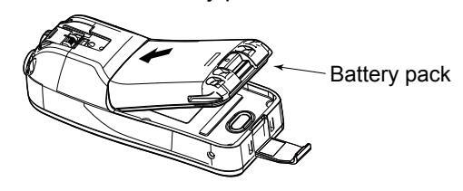
CAUTION: DO NOT attach the battery unless the flexible antenna, battery pack and jack cover are securely attached to the transceiver. Confirm that the antenna and battery pack are dry before attaching. Exposing the inside of the transceiver to dust or water can cause serious damage to the transceiver.
CAUTION: DO NOT place or leave the transceiver in direct sunlight or in places with temperatures below -20°C (-4°F) or above +60°C (+140°F) for IC-M93D, and below -15°C (-10°C for the Australian version) or above +55°C for the IC-M93D EURO. The basic operations of the transceiver are guaranteed within the specified operating temperature range. However, the Liquid Crystal Display may not operate correctly, or show an indication in the case of long hours of operation, or after being placed in extremely cold areas.
CAUTION: DO NOT modify the transceiver. The specifications may change and then the transceiver may not comply with the requirements of required regulations. The transceiver warranty does not cover any problems caused by unauthorized modification.
CAUTION: DO NOT operate the transceiver if it becomes hot after operating it continuously for long periods of time. This may damage the transceiver.
KEEP the transceiver and microphone at least 0.9 m (3 feet) away from the vessel's magnetic navigation compass.
DO NOT push [PTT] unless you actually intend to transmit.
BE CAREFUL! The IC-M93D and IC-M93D EURO meet IPX7* requirements for waterproof protection. However, once the transceiver has been dropped, waterproof protection cannot be guaranteed because of possible damage to the transceiver's case or the waterproof seal.
* Only when the speaker microphone jack cover, the optional HM-165, or HM-228 is attached.
Even when the transceiver power is OFF, a slight current still flows in the circuits. Remove the battery pack from the transceiver when not using it for a long time. Otherwise, the installed battery pack or batteries will become exhausted, and will need to be recharged or replaced.
BE CAREFUL! Even if the volume level is set low, the beeps of the Float 'n Flash, DSC alarm and AquaQuake functions are very loud.
BE SURE the transceiver power is OFF before connecting the supplied or optional equipment.
Icom, Icom Inc. and the Icom logo are registered trademarks of Icom Incorporated (Japan) in Japan, the United States, the United Kingdom, Germany, France, Spain, Russia, Australia, New Zealand, and/or other countries.
RECOMMENDATION
CLEAN THE TRANSCEIVER THOROUGHLY IN A BOWL OF
FRESH WATER after exposure to saltwater, and dry it before operating. Otherwise, the transceiver's keys, switches and controllers may become unusable, due to salt crystallization, and/or the charging terminals of the battery pack may corrode.
NOTE: If the transceiver's waterproof protection appears defective, carefully clean it with a soft, damp (fresh water) cloth, then dry it before operating. The transceiver may lose its waterproof protection if the case, jack cap, or connector cover is cracked or broken, or the transceiver has been dropped. Contact your lcom distributor or your dealer for advice.
DISPOSAL

The crossed-out wheeled-bin symbol on your product, literature, or packaging reminds you that in the European Union, all electrical and electronic products, batteries, and accumulators (rechargeable batteries) must be taken to designated collection locations at the end of their working life. Do not dispose of
these products as unsorted municipal waste. Dispose of them according to the laws in your area.
INFORMATION
This equipment has been tested and found to comply with the limits for a Class A digital device, pursuant to part 15 of the FCC Rules. These limits are designed to provide reasonable protection against harmful interference when the equipment is operated in a commercial environment. This equipment generates, uses, and can radiate radio frequency energy and, if not installed and used in accordance with the instruction manual, may cause harmful interference to radio communications. Operation of this equipment in a residential area is likely to cause harmful interference in which case the user will be required to correct the interference at his own expense.
CAUTION: Changes or modifications to this transceiver, not expressly approved by Icom Inc., could void your authority to operate this transceiver under FCC regulations.
TABLE OF CONTENTS
| IMPORTANT | i |
|---|---|
| EXPLICIT DEFINITIONS | i |
| ABOUT CE AND DOC | i |
| IN CASE OF EMERGENCY | ii |
| PRECAUTIONS | iii |
| RECOMMENDATION | iv |
| DISPOSAL | iv |
| INFORMATION | V |
| 1. OPERATING RULES | 1 |
| 2. SUPPLIED ACCESSORIES AND ATTACHMEN | NTS2–3 |
| Supplied accessories | 2 |
| Attachments | 2 |
| 3. PANEL DESCRIPTION | 4–8 |
| Panel description | 4 |
| Display description | 5 |
| Using the software keys | 7 |
| Software keys | 7 |
| 4. PREPARATIONS | 9–10 |
| Entering the MMSI code | 9 |
| Entering the ATIS ID | |
| (For Dutch and German versions) | 10 |
| 5. BASIC OPERATIONS | 11–15 |
| Selecting a channel | |
| Adjusting the volume level | 13 |
| Adjusting the squelch level |
| Setting the Call channel | 13 |
|---|---|
| Receiving and transmitting | 14 |
| Lock function | 14 |
| Monitor function | 15 |
| AquaQuake Water Draining function | 15 |
| ■ Editing a channel name | 15 |
| 6. SCAN (Except for the Dutch version) | 16–17 |
| ■ Scan types | 16 |
| Setting Favorite channels | |
| ■ Starting a scan | |
| (Except for the Dutch version) | 19 |
| I I ۵ | |
| ۱۵ ۱۷ | |
| IC | |
| 8. DSC OPERATION | |
| DSC address ID | 19 |
| Entering the position and time | 21 |
| Sending DSC calls (Distress) | 22 |
| Sending DSC calls (other) | 25 |
| Receiving DSC calls (Distress) | |
| Receiving DSC calls (other) | 41 |
| DSC Log | 46 |
| DSC Settings | 48 |
| - • | |
| 9 OTHER FUNCTIONS | 51-58 |
|
9. OTHER FUNCTIONS
■ MOB (Man OverBoard) |
51–58 |
| Waypoint | 52 |
|---|---|
| Navigation | 54 |
| Compass | 56 |
| GPS/GNSS | 56 |
| Information screen | 58 |
| 10.MENU SCREEN | |
| Using the Menu screen | 59 |
| Menu screen items | 60 |
| Radio Settings items | 61 |
| Configuration items | 63 |
| 11 BATTERY CHARGING | 65-68 |
| Regular battery charger | 67 |
| Optional battery charger | |
| 60 | |
| ■ About the HM_165 | |
| ■ Attaching the HM-165 | 69 |
| 13.TROUBLESHOOTING | 70 |
| 14.SPECIFICATIONS AND OPTIONS | 71 |
| Specifications | 71 |
| Options | 73 |
| 15.CHANNEL LIST | 74–76 |
| 16.SAFETY TRAINING INFORMATION | 77 |
| INDEX | 79_ 00 |
1
OPERATING RULES
Priorities
- Read all rules and regulations pertaining to priorities and keep an up-to-date copy handy. Safety and distress calls take priority over all others.
- You must monitor Channel 16 when you are not operating on another channel.
- False or fraudulent distress calls are prohibited under law.
♦ Privacy
- Information overheard but not intended for you cannot lawfully be used in any way.
- · Indecent or profane language is prohibited.
♦ Radio licenses (1) SHIP STATION LICENSE
You must have a current radio station license before using the transceiver. It is unlawful to operate a ship station which is not licensed.
Inquire through your dealer or the appropriate government agency for a Ship-Radiotelephone license application. This government-issued license states the call sign which is your craft's identification for radio purposes.
(2) OPERATOR'S LICENSE
A Restricted Radiotelephone Operator Permit is the license most often held by small vessel radio operators when a radio is not required for safety purposes. The Restricted Radiotelephone Operator Permit must be posted or kept with the operator. Only a licensed radio operator may operate a transceiver. However, non-licensed individuals may talk over a transceiver if a licensed operator starts, supervises, ends the call and makes the necessary log entries. A current copy of the applicable government rules and regulations is only required to be on hand for vessels in which a radio telephone is compulsory. However, even if you are not required to have these on hand it is your responsibility to be thoroughly acquainted with all pertinent rules and regulations.
NOTE: Even though the transceiver is capable of operation on VHF marine channels 1021, 1023, 1081, 1082 and 1083, according to FCC regulations these simplex channels cannot be lawfully used by the general population in USA waters.
SUPPLIED ACCESSORIES AND ATTACHMENTS
Supplied accessories

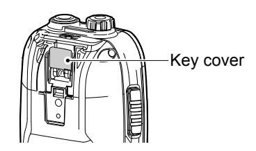
1. Attach the battery pack to the transceiver.
2. Lock the battery pack with the latch.
BE CAREFUL! The latch is tightly locked, so use caution when releasing it. DO NOT use your fingernail. Use the edge of a coin or screwdriver tip to carefully release it
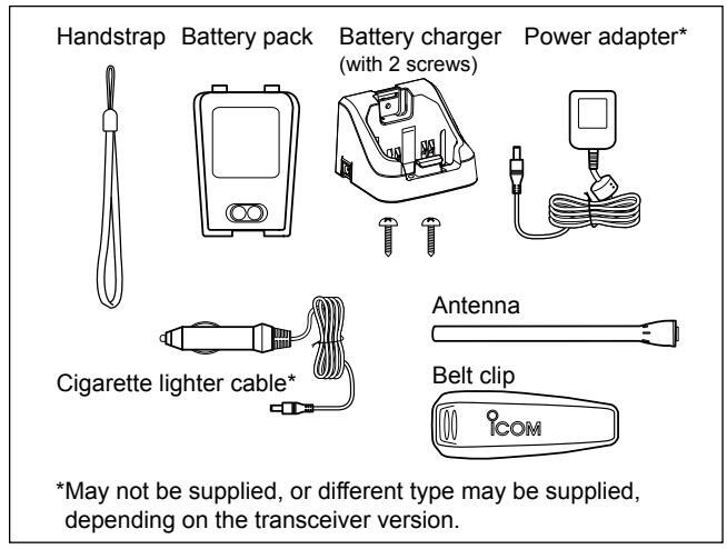
■ Attachments
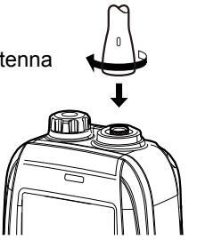
♦ Flexible antenna
Connect the supplied antenna to the anten
CALITION
- NEVER carry the transceiver by holding the antenna
2 SUPPLIED ACCESSORIES AND ATTACHMENTS
■ Attachments (Continued)
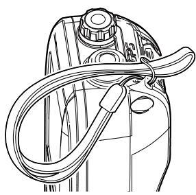
♦ Handstrap
Pass the handstrap through the loop on the back side of the transceiver to make it easy to carry.
♦ Belt clip
Attach or detach the belt clip to/from the transceiver as shown below.
To attach the belt clip
To detach the belt clip
Lift the tab up 1 and slide the belt clip in the direction of the arrow 2 .

2 3
PANEL DESCRIPTION
3
Panel description
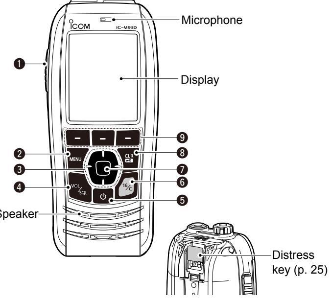
• PTT SWITCH [PTT]
Hold down to transmit, release to receive.
Ø MENU KEY
Push to display or close the Menu screen.
OUP/DOWN/LEFT/RIGHT KEYS [▲]/[▼]/[▲]/[►]
- Push [▲] or [▼] to select the operating channel, Menu items, Menu settings, and so on.
- Push [◄] or [▶] to slide through the key functions that are assigned to the software keys. (p. 7)
- Push to select the desired character or number in the entry mode. (pp. 9, 10, 15, 19, 21)
4 VOLUME/SQUELCH KEY [VOL/SQL] (p. 13)
- Push once to display the volume level setting screen.
- Push twice to display the squelch level setting screen.
- Hold down for 1 second to turn ON the Monitor function. (p. 15)
- ⑤ POWER KEY [()]
Hold down for 1 second to turn the transceiver ON or OFF.
G CHANNEL 16 KEY [16/C]
- Push to select Channel 16. (p. 11)
- Hold down for 1 second to select the Call channel. (p. 11)
O ENTER KEY
Push to set the entered data, selected item, and so on.
③ CLEAR/LOCK KEY [CLR/₊-•]
- Push to cancel the entered data, or to return to the previous screen.
- Hold down for 1 second to turn the Key Lock function ON or OFF. (p. 14)
Panel description (Continued)
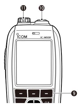
SOFTWARE KEYS Slide through the key functions by pushing [◄] or [▶], and then push either of the 3 software keys to select the function displayed at the bottom of
the display. See "Software keys" on page 7 for details.
(D) ANTENNA CONNECTOR (p. 2)
Connects the supplied antenna.
() SPEAKER MICROPHONE JACK (p. 69)
Connects the optional external speaker microphone.
NOTE: Attach the jack cover when the optional speaker microphone is not used. Otherwise, water will get into the transceiver.
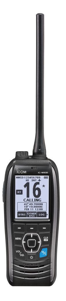
Display description
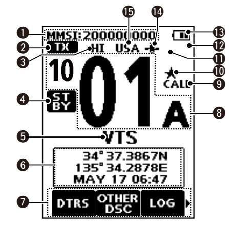
MMSI CODE DISPLAY (p. 9) Displays the entered MMSI code.
-
STATUS ICON (p. 14)
- "TX" is displayed while transmitting.
- "MONI" is displayed while the Monitor function is activated.
- "BUSY" is displayed while receiving, or when the squelch is open.
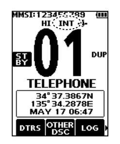
S POWER INDICATOR (p. 8)
- "HI" is displayed when high power is selected.
- "LOW" is displayed when low power is selected.
4 STATUS ICON
- "STBY" is displayed while not receiving nor transmitting
-
"RT" (Radio Telephone mode) is displayed while in the Radio Telephone (RT) mode.
- ①Returns to the Standby mode if no operation occurs during the preset period of time.
- "DSC" is displayed while in the DSC mode.
- The channel name is displayed, if entered, (p. 15)
- "SCAN" or "SCAN 16" is displayed while scanning, (p. 16)
- "DUAL 16" or "TRI 16" is displayed while using the Dualwatch or Tri-watch function. (p. 18)
B POSITION/TIME INDICATOR
Displays the current position and time when valid GPS data is received, or when manually entered. Bassived CBS dates
- "??" blinks if no GPS data is received for 30 seconds after receiving valid GPS data, and then "??" and a warning message are displayed alternately after 10 minutes
- A warning message is displayed if no GPS data is received for 4 hours after receiving valid GPS data.
- "No Position No Time" is displayed if no GPS data is received. for 2 minutes after turning ON the transceiver and then a
warning message is displayed
①"I ocal" is displayed when the UTC Offset time is set (p. 21)
Manually entered GPS data:
A manually entered GPS data is valid for 4 hours, and then a warning message is displayed after 4 hours
①"Manual" is displayed.
O SOFTWARE KEY FUNCTION DISPLAY (pp. 7, 14)
The software key functions are displayed.
- "Key Locked" is displayed while the Lock function is ON. CHANNEL NUMBER READOUT
Displays the selected operating channel number.
9 CALL CHANNEL ICON (p. 11)
Displayed when a Call channel is selected
(D) FAVORITE CHANNEL ICON (p. 17)
Displayed when a Favorite channel is selected.
-
MAIL ICON
(p. 46)
- Displayed when there is an unread message
- Blinks until one of the call messages is read.
DSC SWITCH ICON (p. 48)
- Displayed when the "CH Auto Switch" is set to "lanore" or "Manual"
- Blinks when the "DSC Switch" is OFF
BATTERY INDICATOR
Displays the battery's remaining power
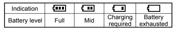
hlinks when the batterv is overcharged (or over voltage
@ GPS ICON
- Stavs ON while valid GPS position data is received
- Blinks while no position data is received
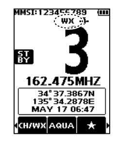
CHANNEL GROUP ICON
- The selected Channel Group's icon is displayed.
- "WX" is displayed for the Weather channel in the USA. Australian, and Export versions. (p. 12)
■ Using the software keys
Various often-used functions are assigned to the software keys for easy access. The functions' icons are displayed above the software keys, as shown below.
♦ Selecting a software key function
- 1. Push [◄] or [▶] to slide through the selectable functions that are assigned to the software keys.
- Push the software key under the function's icon to select the function.
(Example: Selecting a Favorite channel)
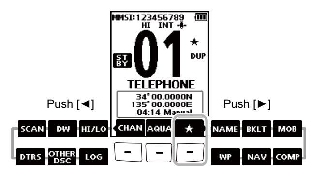
NOTE: The displayed icons, or their order, may differ, depending on the transceiver version or the presetting. Ask your dealer for presetting details.
■ Software keys
You can assign the following functions to the software keys on the Menu screen.
DISTRESS Call
(p. 22)
Push to display the "Distress Call" screen to select the nature of the call, and then to make a call.
NEVER MAKE A DISTRESS CALL IF YOUR SHIP OR A PERSON IS NOT IN AN EMERGENCY. A DISTRESS CALL SHOULD BE MADE ONLY WHEN IMMEDIATE HELP IS NEEDED.
|
other
DSC |
Other DSC
Push to compose an Individual Call, Group C Test Call. |
(p. 25)
Call, or a |
|---|---|---|
| LOG |
LOG
Push to display the received call log or distre message log. |
(p. 46)
ss |
| SCAN |
Scan
Push to start or stop a Normal or Priority sca |
(p. 16)
n. |
Dualwatch/Tri-watch
(p. 18)
Push to start or stop Dualwatch or Tri-watch.
| HI/LO | High/Low | (p. 5) | BKLT | Backlight | (p. 63) |
|---|---|---|---|---|---|
|
Push to set the power to high or low.
①Some channels are set to only low power. |
F | Push to display the backlight creen. | brightness adjustment | ||
| сн/₩Ж | Channel/Weather channel | (pp. 11, 12) | ( | adjust the brightness to betwe |
push [▲]/[▼][◀]/[►] to
en 1 and 7, or OFF. |
|
Push to select regular channels or Wea
() CHAN is displayed except for the USA, Aus |
ther* channels.
stralian, and |
мов | МОВ | (p. 51) | |
|
Export versions.
①While the Call channel or Channel 16 is d this key to return to the regular channel m *The Weather channels are for only the US/ |
isplayed, push
iode. A, Australian, |
|
screen.
nemorize the current oard (MOB) waypoint. |
||
| and Export versions. | WP | Vaypoint | (p. 52) | ||
| AQUA |
AquaQuake
Hold down to turn ON the AquaQuake clear water from the speaker grill. |
(p. 15)
function to |
|
oint" screen.
nemorize the current |
|
| Favorite channel | (n. 17) | NAV | Navigation | (p. 54) | |
| * |
|
splayed |
V
P COMP |
Vhile displaying the "MOB" of
bush this key to start navigat position. |
אד "Waypoint" screen,
ing to the selected |
| While a Favorite channel is displayed | d, hold down | ( | Compass | (p. 56) | |
| NAME | Channel Name |
annei setting.
(p. 15) |
-
F V |
Push to display the "Compas
ressel's course heading, Spe and Course Over Ground (Ci |
s" screen to check the
ed Over Ground (SOG) |
| 6 | 50, |
Push to edit the name of the displayed channel.
PREPARATIONS
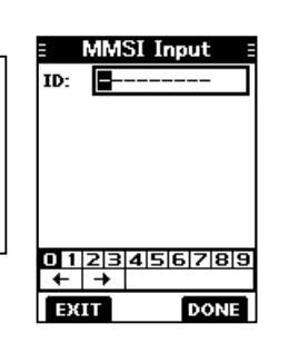
■ Entering the MMSI code
The Maritime Mobile Service Identity (MMSI: DSC self ID) code consists of 9 digits. You can only enter the code when turning ON the transceiver for the first time.
This initial code entry can be done only once. After entering, it can be changed only by your dealer or distributor. If your MMSI code has already been entered, this entry is not necessary.
-
1. Hold down [0] to turn ON the transceiver.
- Three short beeps sound, and "Push [ENT] to Register your MMSI" is displayed.
-
2. Push [ENT] to start entering the MMSI code
- The "MMSI Input" screen is displayed. () Push [CLR] twice to skip the entry.
If you skip the entry, you cannot make a DSC call. To enter the code after skipping, turn OFF the power, and then turn it ON again.
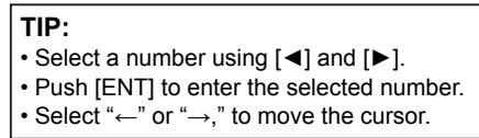
3. Enter the MMSI code.
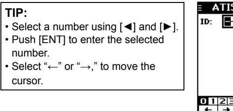
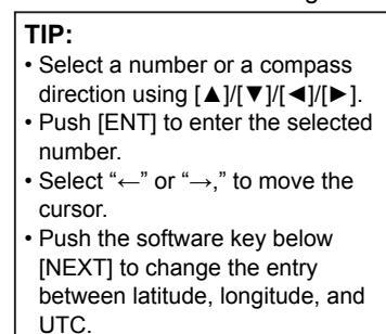
| TIP: |
|---|
|
| Push [ENT] to enter the selected |
| number. |
|
| cursor. |
- 4. Repeat step 3 to enter all 9 digits.
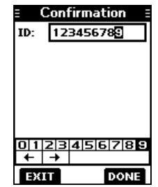
- 5. Push the software key below [DONE] to set the entered code.
The "Confirmation" screen is displayed
- 6. Enter your MMSI code again to confirm.
-
7. Push the software key below [DONE] to set the entered code.
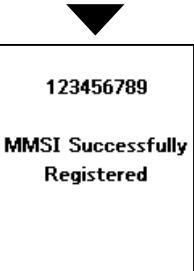
- When your MMSI code is successfully entered, "MMSI Successfully
Registered" is briefly displayed, and then the operating screen opens.
①Your MMSI code is also displayed on the operating screen.
NOTE: For the Dutch and German versions, entering the ATIS ID is also required. See the next page for details.
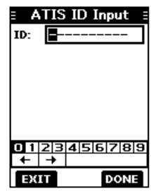
Entering the ATIS ID (For Dutch and German versions)
The Automatic Transmitter Identification System (ATIS) ID consists of 10 digits. You can enter the ID in the "ATIS ID Input" item on the Menu screen.
This ID entering can be done only once. After entering, it can be changed only by your dealer or distributor. If your ATIS ID has already been entered, this entry is not necessary.
-
1. Push [MENU].
- The Menu screen is displayed.
-
Push [▲] or [▼] to select "ATIS ID Input," and then push [ENT] to start entering.
- The "ATIS ID Input" screen is displayed.
- 3. Enter your ATIS ID.
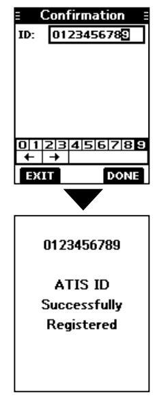
- 4. Repeat step 3 to enter all 10 digits
-
Push the software key below [DONE] to set the entered ID.
- The "Confirmation" screen is displayed.
- 6. Enter your ATIS ID again to confirm.
-
7. Push the software key below [DONE] to set the entered ID.
- (1) When your ATIS ID is successfully entered, the screen displays "ATIS ID Successfully Registered," and then the operating screen opens.
- ①You can check the ATIS ID in "Information" on the Menu screen.
5
BASIC OPERATIONS
■ Selecting a channel
NOTE: Before using the transceiver for the first time, the battery pack must be fully charged for optimum life and operation. To avoid damage to the transceiver, turn OFF the transceiver before charging.
♦ Channel 16
Channel 16 is the distress and safety channel. It is used to establish the initial contact with a station and for emergency communications. Channel 16 is monitored during both Dualwatch and Tri-watch. While in the standby mode, you must monitor Channel 16.
Push [16/C] to select Channel 16. (1) To return to the previously selected channel, push the software key below [CHAN] or [CH/WX].
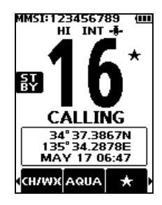
♦ Call channel
Each Channel Group has separate leisure-use Call channels. The Call channel is monitored during Tri-watch. The Call channels can be selected and used to store your most often used channel in each Channel Group, for quick recall.
①See page 13 for details on setting the Call channel.
Hold down [16/C] for 1 second to select the Call channel.
- The Call channel number and "CALL" are displayed.
- (1) To return to the previously selected channel, push the software key below [CHAN] or [CH/WX].
BASIC OPERATIONS 5
♦ Selecting a Channel Group
Channel Groups are preset into your transceiver. You can select the Channel Group between USA, International, Canadian, DSC, and ATIS depending on the transceiver version.
| Varaian | Preset | Channel | Group | ||
|---|---|---|---|---|---|
| version | USA | INT | CAN | DSC | ATIS |
| USA | ✓ | ✓ | ✓ | ||
| UK | ✓ | ✓ | |||
| European | ✓ | ||||
| Dutch | ✓ | ✓ | |||
| German | ✓ | ✓ | ✓ | ||
| Australian |
|
~ | |||
| Export (Other) |
|
✓ | ✓ |
- Push [MENU]. The Menu screen is displayed.
-
Push [▲] or [▼] to select "Radio Settings," and then push [ENT].
- The "Radio Settings" screen is displayed.
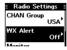
- Push [▲] or [▼] to select "CHAN Group," and then push [ENT]. The "CHAN Group" screen is displayed.
-
Push [▲] or [▼] to select the Channel Group, and then push [ENT].
①Select [EXIT] to exit the Menu
- ③Select [EXIT] to exit the Menu screen.
- The selected Channel Group's icon is displayed on the operating screen.
| ∃ Radio Set | tings 🗄 |
|---|---|
|
Dual/Tri-wa
Dualy |
itch
watch |
| CHAN Group | USA |
| WX Alert | Off |
♦ Weather channels and Weather Alert
For the USA, Australian, and Export versions, the transceiver has 10 preset Weather channels. You can use these channels to monitor broadcasts from the National Oceanographic and Atmospheric Administration (NOAA). The transceiver automatically detects a Weather alert tone on the selected weather channel, or while scanning.
Selecting a Weather channel
-
Push the software key below [CH/WX] on the software key
- "WX" is displayed on the operating screen instead of the Channel Group icon.
- Push [▲] or [▼] to select a Weather channel.
Setting the Weather Alert
③See page 61 for details on the Weather Alert function.
- 1. Push [MENU].
- Push [▲] or [▼] to select "Radio Settings," and then push [ENT]. The "Radio Settings" screen is displayed.
-
3. Select "WX Alert," and then push [ENT].
- The "WX Alert" screen is displayed.
-
Select "On with Scan" or "On."
""" is displayed next to the weather
- "" is displayed next to the weather channel icon.

5
BASIC OPERATION
Adjusting the volume level
-
1. Push [VOL/SQL].
- The volume level adjustment screen is displayed
- 2. Push [◀] or [▶] to adjust the volume level between 1 and 20, or OFF. ①You can also push the software key
below [MUTE] to select OFF, or below [LOUD] to set the maximum volume
(1) If no key is pushed for 5 seconds, the screen automatically closes
3. Push [FNT] to set
Adjusting the squelch level
Squelch enables the audio to be heard only while receiving a
-
1 Push [VOL/SQL] twice
- The squelch level adjustment screen is displayed
- 2. Push [◀] or [▶] to adjust the volume level between 1 and 10. or
If no key is pushed for 5 seconds the
adjustment screen automatically closes. 3 Push [FNT] to set
signal that is stronger than the set level. A higher level blocks weak signals, which enables you to receive only stronger signals. A lower level enables you to hear weak signals.

135 34.3105E
135 34.3105c MAY 24 06:24
l Volume
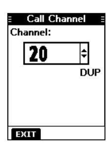
Setting the Call channel
By default, a Call channel is set in each Channel Group. You can set your most often-used channel as your Call channel in each Channel Group for a quick recall
-
1. Push [MENU]
- The Menu screen is displayed.
-
2. Push [▲] or [▼] to select "Radio Settings," and then nush [FNT]
- The "Radio Settings" screen is displayed
-
3. Push [▲] or [▼] to select "Call Channel," and then push [ENT]
- The "Call Channel" screen and the default Call channel is displayed.
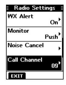
- 4. Push [▲] or [▼] to select the
- 5. Push [ENT] to set the selected ①Push the software key below [EXIT] to return to the operating screen.

BASIC OPERATION 5
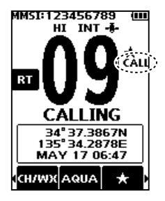
■ Receiving and transmitting
CAUTION: DO NOT transmit without an antenna.
- Push [▲] or [▼] to select the channel to call. ①You cannot transmit on Channel 70. ① EUSY is displayed while receiving a signal.
- Hold down [PTT] and speak into the microphone. TX is displayed while transmitting.
- 3. Release [PTT] to receive.
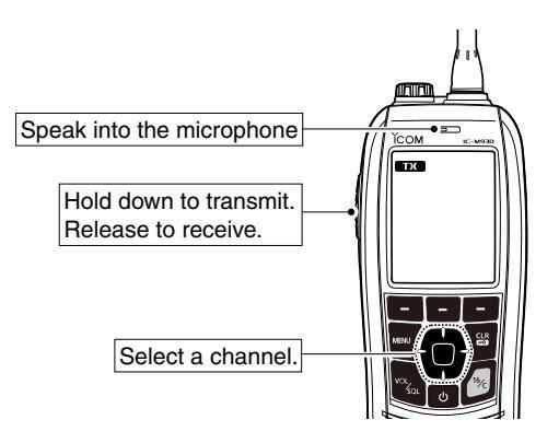
TIP: To maximize the readability of your transmitted signal, pause for a second after pushing [PTT] and hold the microphone 5 to 10 cm (2 to 4 inches) from your mouth, and then speak at your normal voice level.
NOTE:
- To conserve battery power, the Power Save function automatically turns ON when no signal is received for 5 seconds.
- When the temperature is extremely high, the battery protection function automatically sets transceiver power to Low, and disables High power selection.
- Except for the Export version, the Time-out Timer function cuts OFF transmission after 5 minutes of continuously transmitting, to prevent prolonged transmission. 10 seconds before transmission is cut OFF, a beep sounds and "TOT" blinks to indicate that the transmission will be cut OFF. After it is cut OFF, "TIME OUT" is displayed for 10 seconds, and you cannot transmit until it disappears.
- The Noise Cancel function reduces random noise components in the transmit and/or received signal. See page 62 for details.
Lock function
The Lock function electronically locks all keys except for [也], [PTT], and [DISTRESS]. This function enables you to prevent accidentally changing the channel, or accessing the functions.
Hold down [CLR ----] for 1 second to turn the Lock function ON or OFF.
• FOC Key Locked is displayed on the bottom of the display while the Lock function is ON.
5 BASIC OPERATION
Monitor function
The Monitor function temporarily cancels the Squelch function to check for weak signals.
-
Hold down [VOL/SQL] to turn ON the Monitor function.
The Monitor function is ON while [VOL/SQL] is held down.
MINN is displayed
- MONI is displayed
- If there is a weak signal, you can hear the signal and noise.
- 2. Release to turn OFF.
TIP: You can change the Monitor function settings. See page 61 for details.
AquaQuake Water Draining function
Water in the speaker grill may muffle the sound coming from the speaker. The AquaQuake Water Draining function removes water from the speaker grill by vibrating the speaker.
- 1. Push [◀] or [▶] to select AQUA
-
Hold down the software key below ARUA to turn ON the function.
- A low frequency vibration beep sounds to drain the water, regardless of the volume level setting.
- This function is activated for a maximum of 10 seconds, even if you continue to hold down the AquA software key.
- 3. Release the key to turn OFF the function.
NOTE: You cannot use this function when an external speaker microphone is connected.
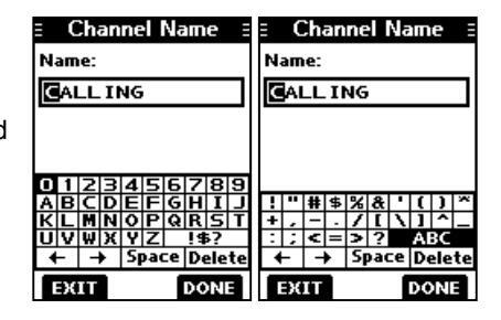
Editing a channel name
You can edit the name of each operating channel and weather channel, using numbers, uppercase letters, symbols, and a space. This enables easy recognition of the channels or stations. All VHF marine channels are set with default names.
- 1. Push [▲] or [▼] to select the channel to edit.
- Push [◄] or [▶] to select NAME. ①You cannot edit a channel name during Dualwatch, Tri-watch, or a Scan.
- Push the software key below NAME. The "Channel Name" screen is displayed
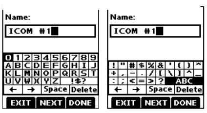
- 4. Edit the channel name.
TIP:
- Select [! $ ?] to enter characters, and select [ABC] to enter numbers and letters.
- Select characters or space using [▲]/[▼]/[◄]/[►].
- Push [ENT] to enter the selected character.
Select "←" or "→," to move the cursor
• Push the software key below EXIT to cancel editing
5. Push the software key below [DONE] to set the edited
■ Scan types
You can find ongoing calls by scanning the Favorite channels.
Before starting a scan, you need to:
-
Set the channels that you want to scan as Favorite channels (n. 17) ①Only the Favorite channels are scanned
- Set the scan type to "Priority Scan" or "Normal Scan" on the "Radio Settings" screen. (p. 61)
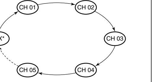
Normal Scan
The Normal Scan sequentially searches through all Favorite channels. However, Channel 16 is not
*For USA, Australian, and Export versions. When the Weather Alert function is ON the previously selected Weather channel is also
Priority Scan
The Priority Scan sequentially searches through all Favorite channels, while also monitoring Channel 16.
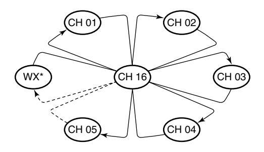
*For LISA Australian and Export versions M/hon the Mosther Mort function is ONL the previously selected Weather channel is also
When a signal is received: On Channel 16 The scan pauses until the signal disappears. On a channel other than Channel 16 The scan becomes Dualwatch until the signal disappears
6 SCAN (Except for the Dutch version)
■ Setting Favorite channels
You can quickly recall often-used channels by setting them as Favorite channels. You can set Favorite channels in each Channel Group.
- 1. Select a Channel Group. (p. 12)
- Push [▲] or [▼] to select the channel you want to set as a Favorite channel.
- 3. Push [◀] or [▶] to display ★
-
4. Hold down the software key below for 1 second.
The selected channel is set as a Favorite channel, and
- " ★ " is displayed.
- To cancel the setting, hold down the key again for 1 second.
TIP: You can set all channels as Favorite channels, clear all settings, or reset to the default. By default, some channels are preset as Favorite channels. The preset channels differ, depending on the transceiver version.
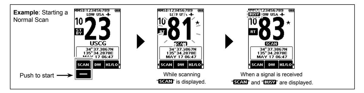
■ Starting a scan
- 1. Select a Channel Group. (p. 12)
- 2. Push [◄] or [►] to display SCAN.
-
3. Push the software key below
SCAN
- The scan starts.
- "SCAN 16" is displayed during a Priority Scan, and "SCAN" is displayed during a Normal Scan.
- When a signal is received, the scan pauses until the signal disappears, or resumes after 5 seconds, depending on the Scan Timer setting in "Radio Settings."
- (DA beep sounds and "16" blinks when a signal is received on Channel 16 during a Priority scan.
- 4. To stop the scan, push the software key below SCAN.
TIP : In order to properly receive signals, be sure to adjust the squelch to a suitable level.
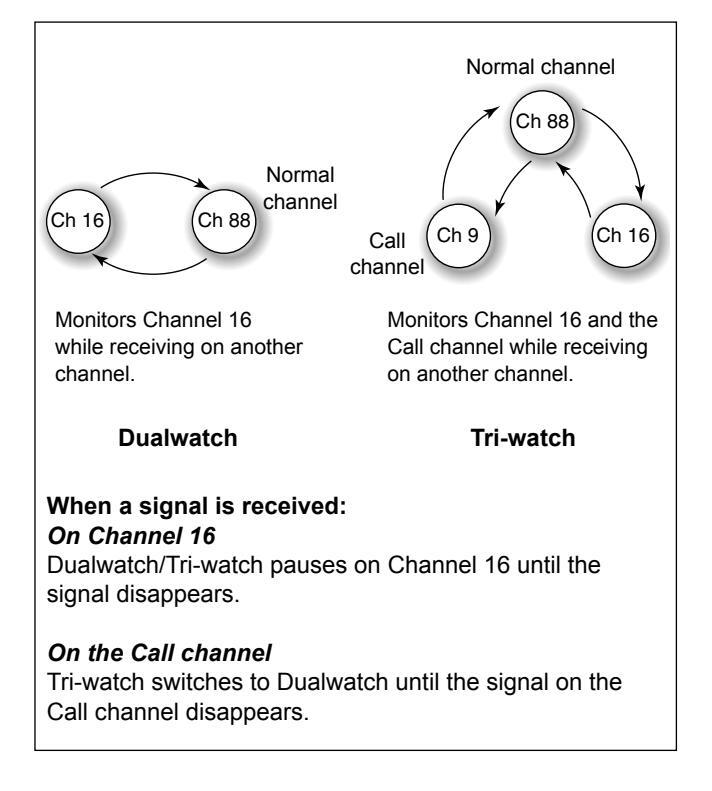
DUALWATCH/TRI-WATCH (Except for the Dutch version)
Description
Dualwatch and Tri-watch are convenient to monitor Channel 16 while you are operating on another channel.
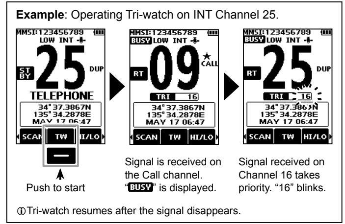
Operation
- Select Dualwatch or Tri-watch in "Radio Settings." (p. 61)
- 2. Push [▲] or [▼] to select a channel.
- 3. Push [◀] or [▶] to display w (Dualwatch) or w (Tri-watch).
-
Push the software key below the wood or wood or the software here to bush and the starts.
- "DUAL 16" is displayed for Dualwatch, and "TRI 16" is displayed for Tri-watch.
Deeps sound when a signal is received on Channel 16.
To cancel Dualwatch or Tri-watch, push the software key again.
■ DSC address ID
8
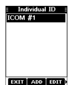
♦ Entering an Individual ID
You can enter a total of 75 Individual IDs, and assign names of up to 10 characters.
1. Display the "Individual ID" screen.
[MENU] ► "DSC Settings" ► "Individual ID"
- "No ID" is displayed if no ID is entered.
-
2. Push the software key below וחחם
- The Individual ID's entry screen is displayed
| Ξ | Individual ID | |
|---|---|---|
| ID: | ||
| Nam | ie: | |
| _ | ||
| ₩ 1 | 9 | |
| EX | 1 |
2 Enter the Individual ID
NOTE: the first digit is fixed as "0" for a Group ID. The first two digits are fixed as "0" for any Coast station ID
4. Push the software key below [NEXT] to start entering

- Select [! $ ?] to use characters, and select [ABC] to use
- Select characters or space using [▲]/[▼]/[◀]/[▶].
- Push [ENT] to enter the selected character
- Select "←" or "→," to move the cursor
5. After entering, push the software key below [DONE] to save, and return to the previous screen. The entered name is displayed
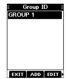
♦ Entering a Group ID
You can enter a total of 25 Group IDs, and assign names of up to 10 characters.
1. Display the "Group ID" screen.
[MENU] ► "DSC Settings" ► "Group ID"
- "No ID" is displayed if no ID is entered
- Push the software key below [ADD]. The Group ID's entry screen is displayed.
- 3. Enter the Group ID and its name in the same way as described on the previous page.
NOTE: The first digit is fixed as "0" for a Group ID. The first two digits are fixed as "0" for any Coast station ID.
-
4. After entering, push the software key below [DONE] to save, and return to the previous screen.
- The entered name is displayed.
♦ Deleting an Individual ID or Group ID
[Example: Deleting an Individual ID: ICOM #2]
1. Display the "Individual ID" screen.
[MENU] ► "DSC Settings" ► "Individual ID"
- 2. Push [▲] or [▼] to select "ICOM #2."
- 3. Push [▶] to display [DEL].
| = Individual ID = | |
|---|---|
| ICOM #1 | |
| ICOM #2 | |
| ICOM #3 | |
| ICOM #4 | |
| ICOM #5 | |
4. Push the software key below [DEL].
• "Are you sure?" is displayed.
-
Push the software key below [OK] to delete.
Push the software key below [CANCEL] to cancel the deletion.
- The selected ID is deleted, and then returns to the previous screen.
TIP : You can edit an ID and its name by pushing the software key below [EDIT] in step 3.
Entering the position and time
A Distress call should include the vessel's position and time. If no GPS data is received, manually enter the position and Universal Time Coordinated (UTC) time.
NOTE
• The manual entry is disabled while the GPS data is received.
The manually entered position and time is valid only for 4 hours, or until turning OFF the transceiver.
- Display the "Position Input" screen. IMENUI ► "DSC Settings" ► "Position Input
- 2. Enter the latitude and longitude.
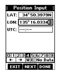
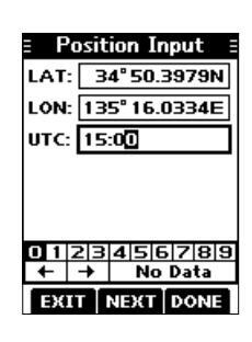
Push the software key below [NEXT] to start entering the UTC time.
①Use the TIP in step 2 to enter.
-
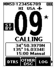
4. Push the software key below [DONE] to set the entered position and time.
- Returns to the previous screen.
- The entered position and time are displayed on the operating screen.
- ① "Manual" is displayed next to the time display.
■ Sending DSC calls (Distress)
A Distress call should be sent if, in the opinion of the Master, the ship or a person is in distress and requires immediate assistance.
NEVER MAKE A DISTRESS CALL IF YOUR SHIP OR A PERSON IS NOT IN AN EMERGENCY. A DISTRESS CALL SHOULD BE MADE ONLY WHEN IMMEDIATE HELP IS NEEDED.
♦ Simple call
- 1. Confirm that no Distress call is being received.
-
2. While lifting up the key cover, hold down [DISTRESS] for 3 seconds until you hear 3 short countdown beeps and a long beep sound.
- The backlight blinks.
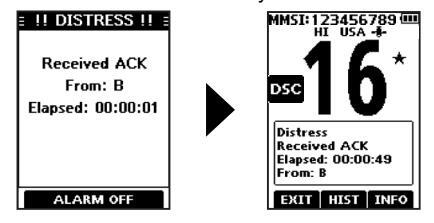
- After sending, wait for an Acknowledgement call. "Waiting for ACK" is displayed.
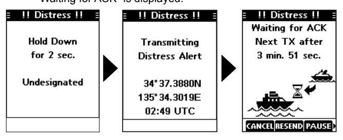
- The Distress call is automatically sent every 3.5 to 4.5 minutes, until an Acknowledgement is received, or a Distress Cancel call is sent. (p. 24)
- () When you receive an Acknowledgement, alarm sounds.
Push any software key to turn OFF the alarm. Channel 16 is automatically selected.
- 5. Hold down [PTT] to explain your situation.
- Push the software key below [EXIT] to return to the operating screen.
TIP: A default Distress alert contains:
Nature of distress: Undesignated distress
• Position information: The latest GPS, or manually input position, which is held for 4 hours or until turning OFF the transceiver.
NOTE on Distress calls (Simple calls and Regular calls) : If no valid position data is received when sending a
Distress call, the transceiver waits for 15 seconds until position data is received, and then the Distress call is sent. If no position is received during this 15 seconds, the position data in the transceiver memory is automatically sent. However, if there is no position data in the memory, the Distress call is sent without position data.
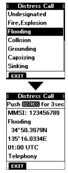
♦ Regular call
Select the nature of the Distress call to include in the Regular Distress call.
- Push the software key below DTRS. The "Distress Call" screen is displayed.
-
Push [▲] or [▼] to select the nature of the call, and then push [ENT]. (Example: Flooding)
- The confirmation screen is displayed.
- If no valid GPS data is being received, the latitude, longitude, and UTC entry mode is displayed. See "Entering the position and time"
- O See "Entering the position and tir on page 22 for details."
- While lifting up the key cover, hold down [DISTRESS] for 3 seconds until you hear 3 short countdown beeps and a long beep sound. The backlight blinks
TIP : You can also send a Regular call by selecting the "Compose Distress" item on the Menu screen.
4. After sending, wait for an Acknowledgement call. • "Waiting for ACK" is displayed.
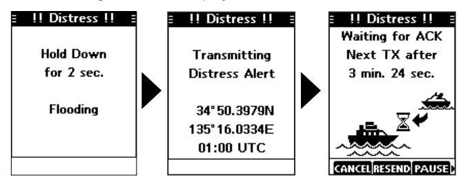
The Distress call is automatically sent every 3.5 to 4.5 minutes, until an Acknowledgement is received, or a Distress Cancel call is sent. (p. 24)
(1) When an Acknowledgement is received, an alarm sounds.
5. Push any software key to turn OFF the alarm.
Channel 16 is automatically selected.
6. Hold down [PTT] to communicate.
NOTE (For USA and Export versions):
After sending a Distress call without position data
- While waiting for an Acknowledgement, if valid position data is received, the transceiver will automatically send a Distress call
- · Even after exiting the DSC mode, if valid position data is received within 20 minutes after receiving a Distress Acknowledgement the transceiver will automatically send a Distress call again.
♦ Distress call software key description
While waiting for an Acknowledgement:
- [CANCEL]: Cancels the Distress call and enables you to send a Cancel call (See the right column)
- [RESEND] : Enables you to resend the Distress call by holding down [DISTRESS] again.
- [PAUSE]: Pauses the countdown to resend the next
- [INFO] Displays the information of the Distress call that you have sent.
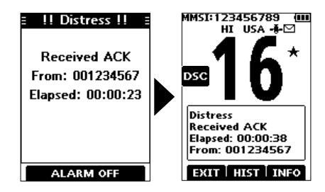
After receiving an Acknowledgement:
- [EXIT]: Closes the Distress operation, and returns to the operating screen
- [HIST] Displays the "Distress History."
- [INFO] Displays the information of the received Distress Acknowledgement.
♦ Distress Cancel call
If you have accidently made a Distress call, or made an incorrect Distress call send a Distress Cancel call to cancel the call as soon as possible while waiting for an Acknowledgement call, and report the purpose of the
- 1. While waiting for an Acknowledgement call, push the software key below [CANCEL]. • The screen below is displayed.
-
2. Push the software key below [CONT]. The Distroce Cancel cell is cent
- Channel 16 is automatically selected.
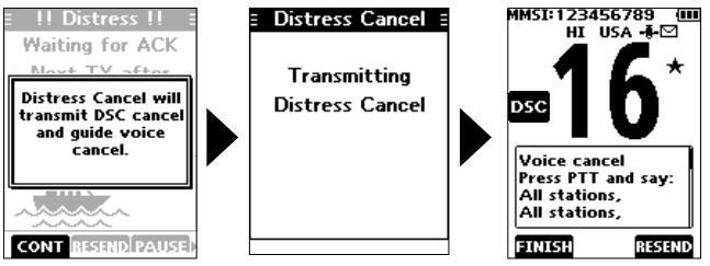
3 Hold down [PTT] to report the purpose of the oon colletion
③You can display the wording of the cancellation by pushing [▼].
4. After communicating, push the software key below
• The screen to the right is displayed.
5. Push the software key below IOK1 to finish the Distress
Returns to the operating screen
■ Sending DSC calls (other)
NOTE: To ensure proper DSC operation, be sure to correctly adjust the "CH 70 SQL Level" item on the Menu screen. (p. 50)
♦ Sending an Individual call
An Individual call enables you to send a DSC signal to only a specific station. You can communicate after receiving the Acknowledgement "Able to comply."
- 1. Push [◀] or [▶] to display
- Push the software key below Office. The "Compose Other" screen is displayed
You can also display the "Compose Other" screen by selecting the "Compose Other" item on the Menu screen
-
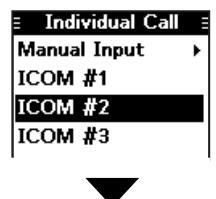
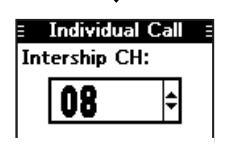
Push [▲] or [▼] to select "Individual Call," and then push [ENT].
- The "Individual Call" screen is displayed.
- Select the station to send an Individual call to, and the push [ENT].
You can also select "Manual Input" to manually enter the calling station
Select a channel to assign, and then push [ENT]. The assigned channels are preset by default.
-
6. Push the software key below [CALL] to send the Individual call.
- "Transmitting Individual Call" is displayed, and then "Waiting for ACK" is displayed.
- If Channel 70 is busy, the transceiver stands by until the channel becomes clear.
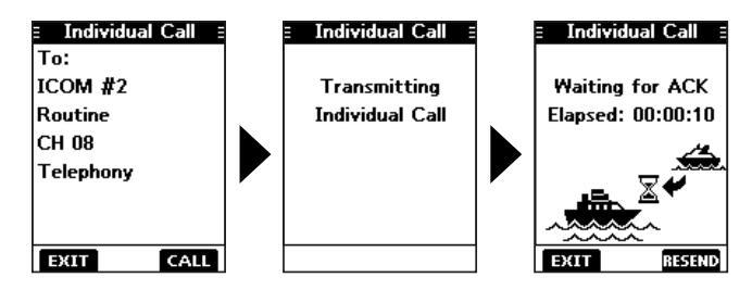
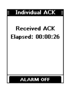
-
When you receive an Acknowledgement "Able to comply":
- An alarm sounds
- The screen to the right is displayed.
-
8. Push any software key to turn OFF the alarm.
- The channel assigned in step 5 is automatically selected.
- If the called station cannot use
the channel that you assigned, a different channel is selected by the station.
9. Hold down [PTT] to communicate
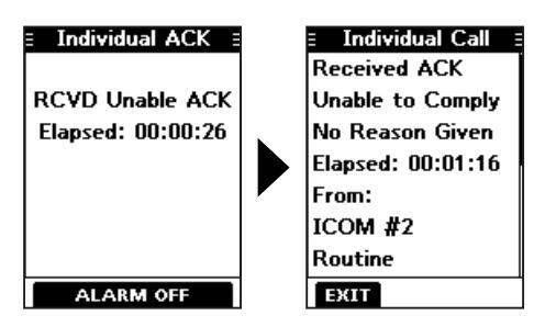
Acknowledgement "Unable to comply"
Push any software key to turn OFF the alarm. The Acknowledge information is displayed. Push the software key below [EXIT] to return to the operating screen.
Sending an Individual Acknowledgement
When you have received an Individual call (p. 41), send an Acknowledgement to the calling station. When you send an Acknowledgement, select "Able to Comply," "Propose New CH," or "Unable to Comply."
- 1. While an Individual call is being received, push any software key to turn OFF the alarm.
- Push the software key below [ACPT]. The received call's information is displayed. ① If you want to send an Acknowledgement "Able to comply
right away, push the software key below [ABLE].
(1) If you cannot communicate, and want to return to the operating screen, push the software key below [IGN].
3. Push the software key below [ACK].
The Acknowledgement category screen is displayed.
Sending an Individual Acknowledgement (Continued)
4. Select "Able to Comply," "Unable to Comply," or "Propose New CH."
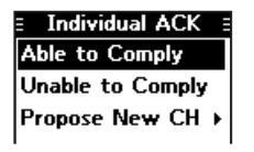
- Able to Comply: Sends an Acknowledgement call without any changes.
- Unable to Comply: Sends an Acknowledgement call but cannot communicate.
- Propose New CH: Able to communicate but proposes

- another channel. Specify the channel by pushing [ ▲ ] or [ ▼ ] (Example: Channel 77)
-
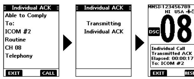
5. Push the software key below [CALL] to send the Acknowledgement call.
- "Transmitting Individual ACK" is displayed, and then the assigned channel is automatically selected.
6. Push [PTT] to communicate.
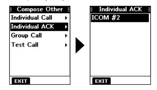
Sending on the "Compose Other" screen
You can also send an Individual Acknowledgement by selecting "Individual ACK" on the "Compose Other" screen. This enables you to resend an Acknowledgement, or send even after sending an "Unable to Comply" Acknowledgement.
- Push the software key below OTHER. The "Compose Other" screen is displayed.
-
Push [▲] or [▼] to select "Individual ACK," and then push [ENT].
- The Individual caller's station or MMSI is displayed. ①"Individual ACK" is not displayed if no Individual call has been received.
- 3. Select the station to send an Acknowledgement call to, and the push [ENT].
4. Repeat steps 3 to 5 described on the left column.
♦ Sending a Group call
A Group call enables you to send a DSC signal to only a specific group.
①You can send a Group call to a pre-entered group address, or manually enter the address before sending. (p. 20)
- 1. Push [◀] or [▶] to display
- 2. Push the software key below . The "Compose Other" screen is displayed. ①You can also display the "Compose Other" screen by
selecting the "Compose Other" item on the Menu screen.
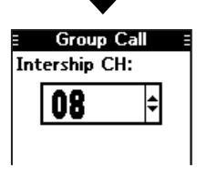
3. Push [▲] or [▼] to select "Group Call," and then push [ENT].
The "Group Call" screen is displayed.
- Select the group to send a Group call to, and the push [ENT]. ①You can also select "Manual Input" to manually enter the target group.
- Manual Input → GROUP 1
- 5. Select the channel to assign, and then push [ENT]. The assigned channels are preset by default
-
6. Push the software key below [CALL] to send the Group call.
- "Transmitting Group Call" is displayed, and then the assigned channel is automatically selected.
- ①If Channel 70 is busy, the transceiver stands by until the channel becomes clear.
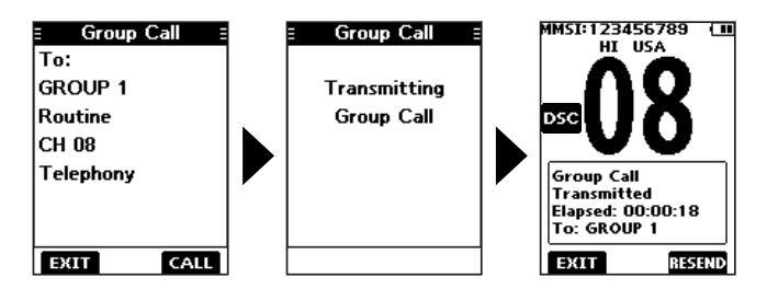
7. Hold down [PTT] to communicate.
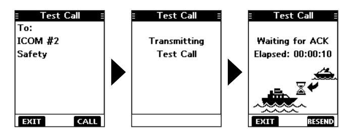
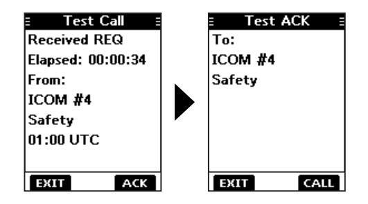
♦ Sending a Test call
You should avoid testing calls on the exclusive DSC distress channels and safety calling channels. When you cannot avoid testing on a distress or safety channel, you should indicate that these are test calls.
Normally the test call would require no further communications between the two stations involved.
- 1. Push [◀] or [▶] to display
- Push the software key below Other. The "Compose Other" screen is displayed
①You can also display the "Compose Other" screen by selecting the "Compose Other" item on the Menu screen.
-
Push [▲] or [▼] to select "Test Call," and then push [ENT].
- The "Test Call" screen is displayed.
| E Test Call | |
|---|---|
| Manual Input | ۲ |
| ICOM #1 | |
| ICOM #2 | |
| ICOM #3 | |
| ICOM #4 | |
| ICOM #5 | |
| EXIT |
4. Select the station to send the Test call to.
①You can also select "Manual Input" to manually enter the calling station.
Push the software key below [CALL] to send the Test call. "Transmitting Test Call" is displayed.
If Channel 70 is busy, the transceiver stands by until the channel becomes clear.
-
6. When you receive an Acknowledgement:
- Alarm sounds.
- The screen to the right is displayed
-
7. Push any software key to turn OFF the alarm.
- The Acknowledgement information is displayed.
-
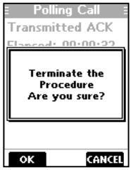
8. Push the software key below [EXIT].
- "Terminate the Procedure Are you sure?" is displayed.
- 9. Push the software key below [OK] to return to the operating screen.
Sending a Test Acknowledgement
By default, when you receive a Test call, the Auto ACK function automatically sends an Acknowledgement to the calling station (p. 48). If the function is set to "Manual," do the following steps to send an Acknowledgement.
- 1. After a Test call is being received, push any software key to turn OFF the alarm.
-
2. Push the software key below [ACPT].
- The received call's information is displayed. (If you want to send an "Able to comply" Acknowledgement right away, push the software key below [ABLE].
-
3. Push the software key below [ACK].
- The "Test ACK" confirmation screen is displayed.
-
4. Push the software key below [CALL] to send the Acknowledgement.
- "Transmitting Test ACK" is displayed.
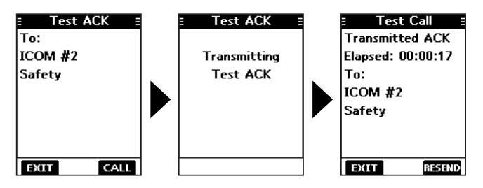
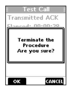
5. Push the software key below [EXIT].
• A confirmation screen is displayed.
6. Push the software key below [OK] to return to the operating screen.
8
Sending a Test Acknowledgement (Continued)
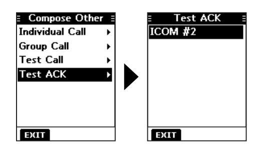
Sending on the "Compose Other" screen
You can also send a Test Acknowledgement by selecting "Test ACK" on the "Compose Other" screen
This enables you to resend an Acknowledgement, or send even after ignoring the call when you first received it.
1. Push the software key below OTHER

- The "Compose Other" screen is displayed
-
2 Push [▲] or [▼] to select "Test ACK " and then push [ENT]
- The Test caller's station or MMSI is displayed.
- ①"Test ACK" is not displayed if no Test call has been received
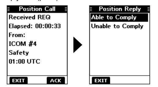
♦ Sending a Position Reply call
Send a Position Reply call when a Position Request call is received. If the Auto ACK function is set to "Auto." the Acknowledgement is automatically sent to the calling station. (p. 48)
- 1. While a Position Request call is being received, push any software key to turn OFF the alarm
-
2 Push the software key below [ACPT]
- The received call's information is displayed
- () If you want to send an "Able to Comply" Acknowledgement right away, push the software key below [ABLE].
- (If you cannot send a reply call push the software key below [UNABL]
3. Push the software key below [ACK].
- 4. Select the reply "Able to Comply."③Select "Unable to Comply" if you cannot send a reply call.
-
5. Push the software key below [CALL] to send the reply.
- "Transmitting Position Reply" is displayed.
- After sending, the replied information is displayed.
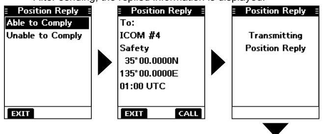
-
6. Push the software key below [EXIT] to return to the operating screen, or below [RESEND] to resend.
- A confirmation screen is displayed.
- 7. Push the software key below [OK] to return to the operating screen.
Position Call Transmitted ACK Elapsed: 00:00:13 To: ICOM #4 Safety 35° 00.0000N 135° 00.0000E
TIP : If no valid position is received while selecting [ACPT] in step 2, and selecting "Able to Comply," the position and time entry screen is displayed.
Sending on the "Compose Other" screen
You can also send a Position Reply call by selecting "Position Reply" on the "Compose Other" screen. This enables you to reply even after ignoring the call when you first received it.
- Push the software key below DSC. The "Compose Other" screen is displayed.
- 2. Push [▲] or [▼] to select "Position Reply," and then push [ENT].
The caller's station or MMSI is displayed.
①"Position Reply" is not displayed if no Position Request call has been received.
3. Select the station to send a Position Reply call to, and the push [ENT].
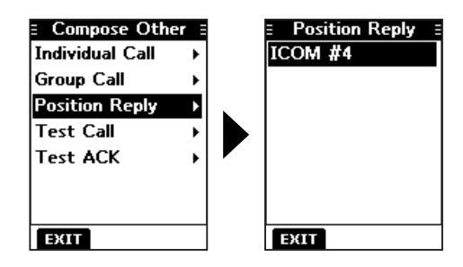
4. Repeat steps 4 to 7 described in the left column.
♦ Sending a Position Request call (For only the USA version)
Send a Position Request call when you want to know if a specific ship's current position, and so on.
- 1. Push [◀] or [▶] to display OTHER
-
2. Push the software key below DSC.
- The "Compose Other" screen is displayed.
- ①You can also display the "Compose Other" screen by selecting the "Compose Other" item on the Menu screen.
- Push [▲] or [▼] to select "Position Request," and then push [ENT].
The "Position Request" screen is displayed.
Select the station to send a Position Request call to, and then push [ENT].
①You can also select "Manual Input" to manually enter the calling station.
| E Position Requesion | st |
|---|---|
| Manual Input | ► |
| ICOM #1 | |
| ICOM #2 | |
| ICOM #3 | |
| EXIT |
-
5. Push the software key below [CALL] to send the Position Request call.
- "Transmitting Position Request" is displayed.
- If Channel 70 is busy, the transceiver stands by until the channel becomes clear.
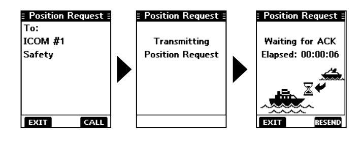
-
6. When you receive an Acknowledgement "Able to Comply":
- Alarm sounds.
- The screen to the right is displayed
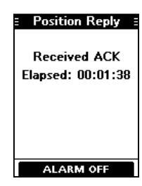
-
7. Push any software key to turn OFF the alarm.
- The screen to the right is displayed.
| E Position Call | |
|---|---|
| Received ACK | |
| Elapsed: 00:01:42 | |
| From: | |
| ICOM #1 | |
| Safety | |
| 35° 00.0000N | |
| 135°00.0000E | |
| EXIT |
8. Push the software key below [EXIT] to return to the operating screen.
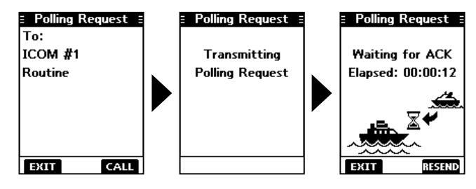
♦ Sending Polling Request call (For only the USA version)
Send a Polling Request call when you want to know if a specific vessel is in the communication area, or not.
- 1. Push [◀] or [▶] to display OTHER
- Push the software key below OBSC. The "Compose Other" screen is displayed
①You can also display the "Compose Other" screen by selecting the "Compose Other" item on the Menu screen.
Push [▲] or [▼] to select "Polling Request," and then push [ENT].
The "Polling Request" screen is displayed.
Select the station to send a Polling Request call to, and then push [ENT].
①You can also select "Manual Input" to manually enter the calling station.
|
∃ Pollir
Manua |
ng Request
I Input |
• |
|---|---|---|
| ICOM | #1 | |
| ICOM | #2 | |
| ICOM | #3 | |
-
5. Push the software key below [CALL] to send the Polling Request call.
- "Transmitting Polling Request" is displayed.
- If Channel 70 is busy, the transceiver stands by until the channel becomes clear.
-
6. When you receive an Acknowledgement:
- Alarm sounds.
- The screen to the right is displayed.
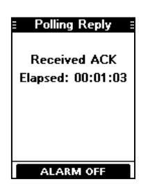
-
7. Push any software key to turn OFF the alarm.
- The screen to the right is displayed.
| E Polling Call E |
|---|
| Received ACK |
| Elapsed: 00:01:17 |
| From: |
| ICOM #1 |
| Routine |
| APR 12 01:38 UTC |
| EXIT |
8. Push the software key below [EXIT] to return to the operating screen.
♦ Sending a Polling Reply call (For only the USA version)
Send a Polling Reply call when a Polling Request call is received. If the Auto ACK function is set to "Auto," the Acknowledgement is automatically sent to the calling station.
- 1. While a Polling Request call is received, push any software key to turn OFF the alarm.
-
2. Push the software key below [ACPT].
- The received call's information is displayed.
If you want to send an Acknowledgement right away, push the software key below [ABLE].
If you cannot send a reply call, push the software key below [IGN].
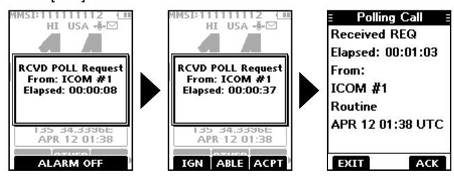
3. Push the software key below [ACK].
-
4. Push the software key below [CALL] to reply.
- "Transmitting Polling Reply" is displayed.
- After sending, the replied information is displayed.
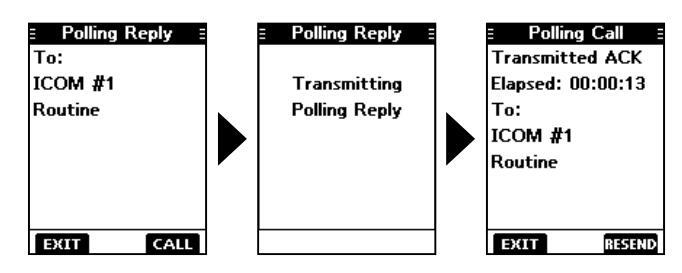
5. Push the software key below [EXIT] to return to the operating screen, or below [RESEND] to resend.
A confirmation screen is displayed.
6. Push the software key below [OK] to return to the operating screen.
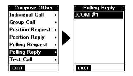
Sending on the "Compose Other" screen
You can also send a Polling Reply call by selecting "Polling Reply" on the "Compose Other" screen. This enables you to reply even after ignoring the call when you first received it.
-
1. Push the software key below OTHER
- The "Compose Other" screen is displayed
-
Push [▲] or [▼] to select "Polling Reply," and then push [ENT].
- The caller's station or MMSI is displayed.
- "Polling Reply" is not displayed if no Polling Request call has been received.
- 3. Select the station to send a Polling Reply call to, and then push [ENT].
4. Perform steps 4 to 6 described in the left column.
Receiving DSC calls (Distress)
The transceiver receives Distress calls, Distress Acknowledgement calls, and Distress Cancel calls. • When you receive a call, an emergency alarm sounds.
NOTE: The screens that are displayed when a Distress call or an Acknowledgement call is received slightly differ from one another. The following steps are described using an example of receiving a Distress call.
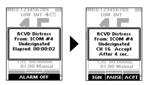
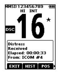
When a Distress call is received:
- The emergency alarm sounds until you turn it OFF.
- "RCVD Distress" is displayed.
- 1. Push any software key to turn OFF the alarm.
- 2. Push the software key below the intended operation.
[IGN]
- · Returns to the operating screen.
- The call is saved in the DSC Log.
- "" blinks continuously until you display the call message.
[PAUSE]
①[PAUSE] is not displayed if the "CH Auto Switch" item is set to "Manual." (p. 48)
- Pauses the countdown until the assigned channel is automatically selected.
- Select [RESUME] to resume the countdown.
- The call is saved in the DSC Log.
[ACPT]
Accepts the call.
- Channel 16 is automatically selected.
- Monitor Channel 16 as a coast station may require assistance.
-
After Channel 16 is selected, you can select your next operation by pushing the software key below the following options.
- [EXIT]: Returns to the operating screen.
- [HIST]: Displays the "Distress History" screen.
-
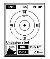
[POS]: Displays the position of the calling station on a map*.
- The map is not updated, even as your vessel moves.
- [INFO]: Displays the information of the received Distress call.
*Note on the map: See "Navigation screen description" on page 55 for details on "RNG," "N-UP," "BRG," and "DIST."
■ Receiving DSC calls (other)
The transceiver receives the following types of DSC calls • Individual call (p. 41)
- Individual Acknowledgement call (p. 25)
- Group call (p. 42)
- All Ships call (p. 43)
- Position Request call (p. 44)
- Test call (p. 45)
- Test Acknowledgement call (p. 46)
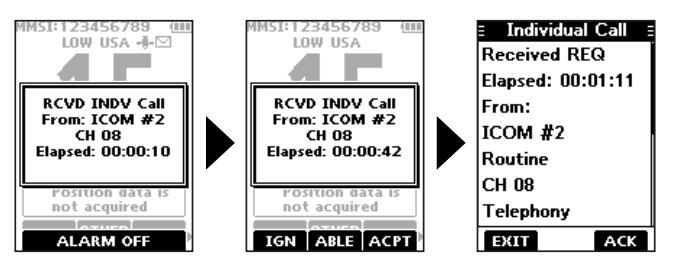
♦ Receiving an Individual call
When an Individual call is received:
- The alarm sounds
- "RCVD INDV Call" is displayed.
- 1. Push any software key to turn OFF the alarm.
- 2. Push the software key below the next operation.
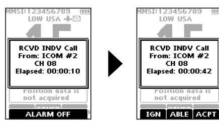
[IGN]
- · Ignores the call and returns to the operating screen.
- The call is saved in the DSC Log.
- "" blinks continuously until you display the call message.
[ABLE]
- Sends an Individual Acknowledgement call right away.
- The assigned channel is automatically selected.
- · After sending, [RESEND] to resend
- The call is saved in the DSC Log
[ACPT]
- Accepts the call.
- The assigned channel is automatically selected.
- The call is saved in the DSC Log.
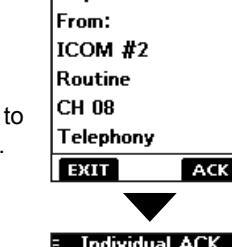
- The received call's information is displayed.
- Push the software key below [ACK] to select the Acknowledgement option.
Able to Comply:
Sends an Acknowledgement call without any changes.
Unable to Comply:
Sends an Acknowledgement but you
cannot communicate.
Propose New CH
Sends an Acknowledgement call but on another channel. Assign the channel by
pushing [▲] or [▼].
Individual Call
Received REQ
Able to Comply Unable to Comply Propose New CH >
NOTE : If the Auto ACK function is set to "Auto (Unable)" the Acknowledgement "Unable to Comply" is automatically sent to the calling station when the call is received. (p. 48) () For the USA and Export versions, this function is set to "Auto (Unable)" by default.
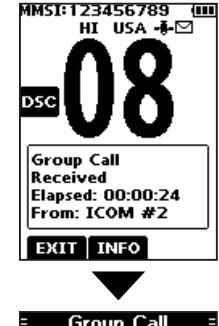
♦ Receiving a Group call
When a Group call is received:
- The alarm sounds for 2 minutes.
- "RCVD Group Call" is displayed.
- Push any software key to turn OFF the alarm. The channel that is assigned by the caller is automatically selected after 10 seconds by default.
- 2. Push the software key below your next operation.
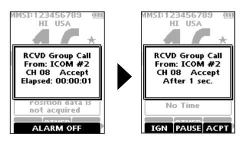
[IGN]
- Ignores the call and returns to the operating screen.
- The call is saved in the DSC Log.
- " blinks continuously until you display the call message.
[PAUSE]
- ①[PAUSE] is not displayed if the "CH Auto Switch" item is set to "Manual." (p. 48)
- Pauses the countdown until the assigned channel is automatically selected.
- Select [RESUME] to resume the countdown.
- The call is saved in the DSC Log.
[ACPT]
- Accepts the call.
- The assigned channel is selected.
- The call is saved in the DSC Log.
[EXIT]
Closes the Group call, and then returns to the operating screen.
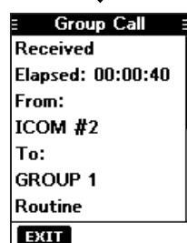
[INFO]
The received call's information is displayed.
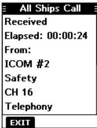
♦ Receiving an All Ships call
When an All Ships call is received:
- The alarm sounds.
- "RCVD All Ships Call" is displayed.
- Push any software key to turn OFF the alarm. The traffic channel that is assigned by the caller is automatically selected after 10 seconds by default.
- 2. Push the software key below your next operation.
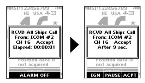
[IGN]
- Ignores the call and returns to the operating screen.
- The call is saved in the DSC Log.
- " " blinks continuously until you display the call message.
[PAUSE]
①[PAUSE] is not displayed if the "CH Auto Switch" item is set to "Manual." (p. 48)
- Pauses the countdown until the assigned channel is automatically selected.
- Select [RESUME] to resume the countdown.
- The call is saved in the DSC Log.
[ACPT]
- Accepts the call.
- The assigned channel is selected.
- The call is saved in the DSC Log.
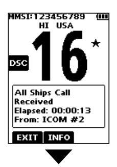
[EXIT]
Closes the All Ships call, and then returns to the operating screen.
[INFO]
The received call's information is displayed.
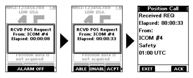
♦ Receiving a Position Request call
When a Position Request call is received:
- The alarm sounds for 2 minutes.
- "RCVD POS Request" is displayed.
- 1. Push any software key to turn OFF the alarm.
- Push the software key below the intended operation.
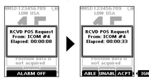
[ABLE]
- · Sends the Acknowledgement "Able to Comply."
- The call is saved in the DSC Log.
[UNABL]
- Sends the Acknowledgement "Unable to Comply."
- Displays the Acknowledgement information, and then returns to the operating screen by pushing the software key below [EXIT].
- The call is saved in the DSC Log.
[ACPT]
- Accepts the call.
- Displays the received call's information.
- The call is saved in the DSC Log.
- Push the software key below [ACK] to send the Position Reply call. (p. 39)
[IGN]
- Ignores the call and returns to the operating screen.
- The call is saved in the DSC Log.
- "" blinks continuously until you display the call message.
NOTE
• If the Auto ACK function is set to "Auto," the Position Reply is automatically sent to the calling station. (p. 48)
However, even if the Auto ACK function is set to "Manual," after receiving a Distress Acknowledgement, or while in the Distress Cancel call procedure, the Position Reply is automatically sent to the calling station.
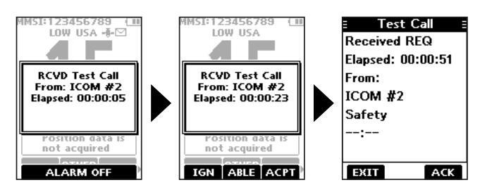
♦ Receiving a Test call
TIP: By default, the Auto ACK function automatically sends an Acknowledgement to the calling station (p. 48). If the function is set to "Manual," the following screens are displayed.
When a Test call is received:
- The alarm sounds for 2 minutes.
- "RCVD Test Call" is displayed.
- 1. Push any software key to turn OFF the alarm.
- 2. Push the software key below your next operation.
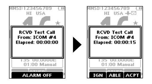
[IGN]
- · Ignores the call and returns to the operating screen.
- The call is saved in the DSC Log
- """ blinks continuously until you display the call message
[ABLE]
- Sends the Acknowledgement "Able to Comply."
- The call is saved in the DSC Log.
[ACPT]
- · Accepts the call.
- Displays the received call's information.
- The call is saved in the DSC Log
- Push the software key below [ACK] to send a Test Acknowledgement call. (p. 30)
- Push the software key below [RESEND] to resend.
NOTE : If the Auto ACK function is set to "Auto," the Test Acknowledgement call is automatically sent to the calling station when the call is received. (p. 48)
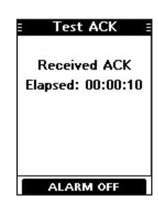
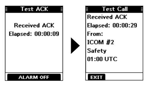
Receiving a Test Acknowledgement call
After sending a Test call, the called station will send you a Test Acknowledgement call.
When a Test Acknowledgement call is received:
- The alarm sounds for 2 minutes.
- "Received ACK" is displayed.
Push any software key to turn OFF the alarm.
- The received call's information is displayed.
- The call is saved in the DSC Log.
- ①Push the software key below [EXIT] to return to the operating screen.
■ DSC Log
♦ Received DSC Log
The transceiver saves up to 50 received Distress call messages and 50 received "Others" call messages in your DSC Log.
On the operating screen, " is displayed when there is an unread call message.
- 1. Display the "DSC Log" screen. [MENUI ► "DSC Log"
-
Push [▲] or [▼] to select "Received," and then push [ENT].
- The "Received" screen is displayed.
-
Push [▲] or [▼] to select
"Distress" or "Others," and then push [ENT].
- ① "Distress" displays the received Distress call log, and "Others" displays the received DSC call log
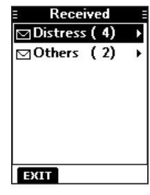
TIP: You can also display the "Received" screen by pushing the software key below too on the operating screen.
♦ Received DSC log (Continued)
- 4. Push [▲] or [▼] to scroll through the log.
- Push [ENT] to display the received call's information.
Received Distress log
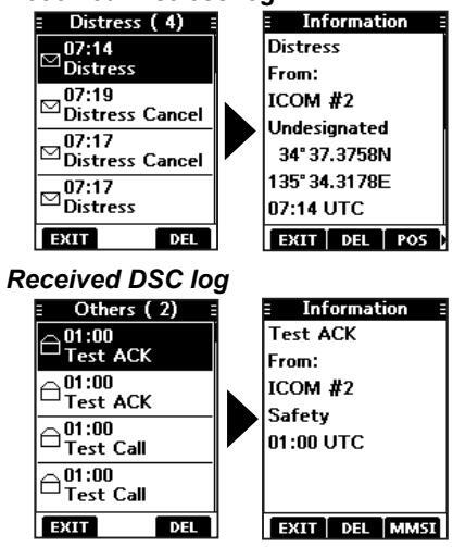
- [EXIT]: Returns to the operating screen.
- [DEL]: Deletes the selected call log. ①Confirmation screen is displayed before deleting.
- [POS]: Displays the position of the called station. ①This option is not displayed if no position data is received.
- [MMSI]: Saves the MMSI as an Individual ID.
- [WP]: Enters the received position as a Waypoint. (p. 53)
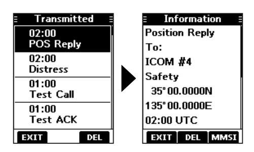
♦ Sent DSC Log
The transceiver saves up to 50 DSC sent calls in your DSC Log.
1. Display the "DSC Log" screen.
[MENU] ► "DSC Log"
Push [▲] or [▼] to select "Transmitted," and then push [ENT].
The "Transmitted" screen is displayed
- Push [▲] or [▼] to scroll through the log.
- Push [ENT] to display the sent call's information.
■ DSC Settings
On the "DSC Settings" screen, you can make settings on the DSC call related items.
Position Input
See "Entering the position and time" on page 21 for details
Individual ID
See "Entering an Individual ID" on page 19 for details.
Group ID
See "Entering a Group ID" on page 20 for details.
Auto ACK
The Auto ACK function automatically sends an Acknowledgement call when the following calls are received.
- Individual call (Default: Differs depending on the version)
- Position Request call (Default: Manual)
- Test call (Default: Auto)
Manual : Manually send an Acknowledgement call. Auto : Automatically send an Acknowledgement call.
TIP: When "Auto" is set to the Individual call, the Acknowledgement "Unable to Comply" is automatically sent when the call is received.
CH Auto Switch
(Default: Accept)
Select whether or not to automatically switch to channel 16 or the specified channel, or select whether to switch or ignore the call.
Accept: After receiving a DSC call, the transceiver remains on the operating channel for 10 seconds. After that, the transceiver automatically switches to the channel that is specified on the DSC call
- Ignore : After receiving a DSC call, if you do not push the software key below [ACPT] in 10 seconds, the transceiver ignores the call, and then remains on the current operating channel.
- Manual: After receiving a DSC call, you can select whether or not to accept the received DSC call.
DSC Switch
(Default: On)
Select whether or not to receive and send DSC calls. ①You can send Distress calls despite of this setting.
- On : Receives and sends DSC calls.
- Off (TEMP) : Does not receive or send DSC calls until you turn OFF the transceiver.
- Off: Does not receive or send DSC calls.
DSC Settings (Continued)
Unread Return
(Default: On)
This function puts the received DSC call on hold while receiving another call.
On: While receiving another call, the received DSC call is put on hold until the currently receiving call is hung up.Off: While receiving another call, the received DSC call is saved in the DSC Log.
MOB Auto Set
• MOB Key (Default: On (30 sec))
For 30 seconds after entering the MOB waypoint, this function automatically sets the Nature of Distress as "Man Overboard."
- On (30 sec): The Nature of Distress is automatically set to "Man Overboard" for 30 seconds after entering the MOB waypoint. Off: The function is OFF
- Water Detection (Default: On (30 sec))
For 30 seconds after the transceiver has detected water, this function automatically sets the Nature of Distress as "Man Overboard."
- On (30 sec): The Nature of Distress is automatically set to "Man Overboard" for 30 seconds after the transceiver has detected water.
- Off: The function is OFF.
Alarm Status
Set the alarm ON or OFF for each DSC related item.
- Safety (Default: On) An alarm sounds when a Safety DSC call is received.
- Routine (Default: On) An alarm sounds when a Routine DSC call is received.
- Warning (Default: On)
- An alarm sounds when:
- no MMSI code is entered.
- the position data has not been received for 2 minutes after turning ON the transceiver.
- the received position data has not been updated for 10 minutes.
- the received position data or manually entered position data has not been updated for 4 hours.
- Self-Terminate (Default: On)
An alarm sounds when duplicate Distress calls are received.
• Discrete (Default: On)
An alarm sounds when a lower priority call is received while receiving a high priority call.
CH 70 SQL Level
(Default: 5)
Adjust the Squelch level for Channel 70 to between 1 and 10, or Open.
①" BUSY " is displayed when adjusted to Open.
A higher level blocks weak signals, which enables you to send a DSC call.
DST at PW Off
(Default: Valid)
This function enables you to send Distress calls even while the transceiver is OFF.
- Valid: You can send Distress calls by holding down [DISTRESS], even while the transceiver is OFF.
- Invalid: You cannot send Distress calls while the transceiver is OFF.
Loop Test
This function sends DSC signals to the receiving AF circuit to compare the sending and receiving signals at the AF level.
Push [ENT] to start the Loop Test.
When the sending and receiving DSC signals match, "OK" is displayed.
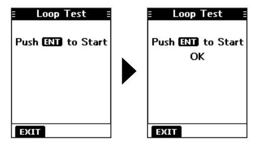
NOTE: If "NG" is displayed, either or both the sending and receiving DSC circuits have a problem. In that case, you will have to send the transceiver to your dealer for repair.
9
OTHER FUNCTIONS
■ MOB (Man OverBoard)
You can enter a Man OverBoard (MOB) waypoint into the transceiver with its GPS position data, as soon as a person has fallen into the water and needs to be rescued. This enables you to reach the MOB position even in the dark, or when you have lost visual contact.
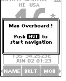
♦ Entering an MOB waypoint
- 1. Push [◀] or [▶] to display MOB
-
Hold down the software key below
MOB for 1 second to enter the MOB waypoint.
- After entering, "Man Overboard!" is displayed.
- You cannot enter the MOB waypoint if no GPS data is received.
- ①You can only enter 1 MOB waypoint, and the previously entered point is overwritten when a new waypoint is entered.
-
3. Push [ENT] to start the navigating to the entered point.
- ①See page 54 for navigation details. ①Push the software key below [EXIT] to stop the navigation and return to
- to stop the navigation and ret the operating screen.
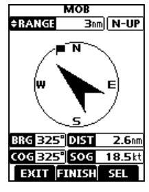
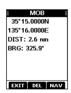
- ♦ MOB screen
- 1. Push [◀] or [▶] to display MOB
- 2. Push the software key below Mos The "MOB" screen is displayed. (i) You can also display the "MOB"
screen by selecting the "MOB" item on the Menu screen.
- ①"No Entry" is displayed if no MOB waypoint is entered.
- Push the software key below [NAV] to start the navigation, [DEL] to delete the entry, and [EXIT] to close the "MOB" screen
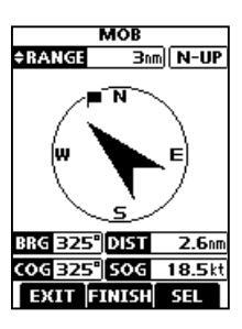
Navigating to the MOB waypoint:
The transceiver can navigate you to the MOB waypoint.
Push the software key below [NAV]. (1) See page 54 for navigation details.
Deleting the MOB waypoint:
-
Push the software key below [DEL] to delete the MOB waypoint.
- "Are you sure?" is displayed.
-
Push the software key below [OK] to delete.
①You can cancel the deletion by pushing the software key below [CANCEL].
- "No Entry" is displayed.
OTHER FUNCTIONS 9
■ Waypoint
Waypoints are GPS position data points of places you want to go to, the position of your own vessel, or of a vessel you received a DSC call from. You can enter up to 50 Waypoints with names of up to 10 characters. You can enter your current position information, or add one as a destination or landmarks you often go to, as information for easy access.
♦ Entering a Waypoint Entering your current position as a Waypoint:
- 1. Push [◀] or [▶] to display we
-
2. Hold down the software key below we for 1 second.
- "Waypoint was stored" is displayed.
- The current position is entered as a Waypoint.
①You cannot register a Waypoint if no GPS data is received.
3. Push [CLR---] to return to the operating screen.
Manually entering a Waypoint:
- 1. Push [◀] or [▶] to display WP
- Push the software key below we The "Waypoint" screen is displayed.
- 3. Push [◀] or [▶] to display [ADD].
-
4. Push the software key below [ADD]
- Enters the Waypoint entry mode
- The current position is displayed in the entry boxes.
MMSI:123456789 (III HI USA -----------------------------------
5. Edit the latitude and longitude.
TIP:
- Select a number or the compass
- direction using [▲]/[▼]/[◀]/[►]. • Push [ENT] to enter the selected number
- Select "←" or "→," to move the cursor.
Push the software key below NEXT to select latitude, longitude, and name.
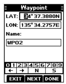
Waypoint entry mod
Entering a Waypoint name:
After editing the latitude and longitude, push the software key below [NEXT] to select "Name."
TIP:
• Select [! $ ?] to use characters, and select [ABC] to use numbers and letters.
- Select characters or space using [▲]/[▼]/[◄]/[►].
- Push [ENT] to enter the selected character
- Select "←" or "→," to move the cursor.
- 2. Push the
below DONE to save the edited name.
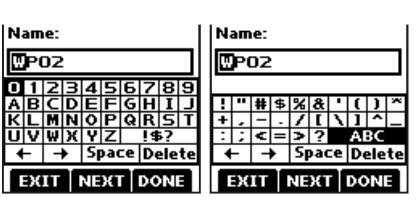
9 OTHER FUNCTIONS
Waypoint (Continued)
♦ Entering a received position
After receiving a Distress call that includes position data, you can enter the position as a Waypoint. This enables you to reach the caller's position.
- 1. Push [◀] or [▶] to display
- 2. Push the software key below Los • The "Received" screen is displayed.
- 3. Push [▲] or [▼] to select "Distress."
-
Select the received call and then push [ENT].
- The received DSC call's GPS position data is displayed on the "Information" screen.
| E Distress |
|---|
|
⊖07:23
Distress Cancel |
|
⊖07:23
Distress |
- Push [◄] or [▶] to display [WP]. "Store Waypoint?" is displayed.
- 6. Push the software key below [OK] to enter.
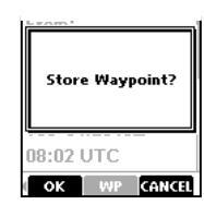
| • | |
|---|---|
| Information | |
| Distress Cancel | |
| From: | |
| 223456789 | |
| Fire, Explosion | |
| 34° 37.3932N | |
| 135° 34.2649E | |
| 08:02 UTC | |
| MMSI WP | |
♦ Waypoint screen
Push [◄] or [▶] to display Push the software key below

- The "Waypoint" screen is displayed. You can also display the "Waypoint" screen by selecting the "Waypoint" item on the Menu screen.
- Push [◀] or [▶] to scroll through [EXIT], [SORT], [NAV], [ADD], [EDIT], and [DEL].
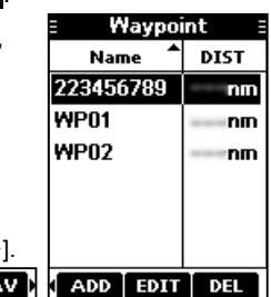
Push [◀] or [▶].
Sorting the Waypoint list:
You can sort the Waypoint list by the Waypoint or MMSI name, or by the distance from your vessel.
Push the software key below [SORT] to sort the list. • "▲" or "▼" is displayed next to "Name" or "DIST." ⊕Each push changes the sorting order.
Navigating to a Waypoint:
The transceiver can navigate you to an entered Waypoint. Push the software key below [NAV]. ①See page 54 for navigation details.
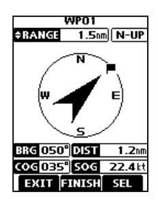
• The position is entered on the "Waypoint" screen.
Adding a Waypoint:
Push the software key below [ADD] to add a Waypoint. ()Add the Waypoint in the same manner that is described in "Manually entering a Waypoint" on page 52.
Editing a Waypoint:
While selecting the Waypoint that you want to edit, push the software key below [EDIT] to edit the Waypoint.
①Edit the Waypoint in the same manner "Manually entering a Waypoint" on page 52 for editing a Waypoint.
Deleting a Waypoint:
- Select the Waypoint that you want to delete, and then push the software key below [DEL] to delete it. "Are you sure?" is displayed.
- Push the software key below [OK] to delete. ①Select [CANCEL] to cancel the deletion.
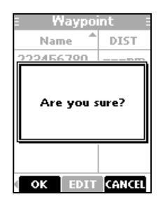
Navigation
The Navigation function navigates from your current position to an entered regular Waypoint or MOB waypoint.
Start navigating to the MOB waypoint:
The MOB waypoint must be entered before navigating.
- 1. Push [◀] or [▶] to display MOB.
- Push the software key below More • The "MOB" screen is displayed.
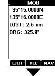
Push the software key below [NAV] to start navigating to the MOB waypoint. The navigation starts.
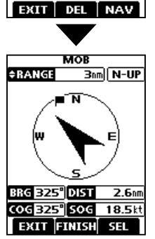
9 OTHER FUNCTIONS
Navigation (Continued)
Start navigating to a Waypoint:
①A Waypoint must be entered before navigating.
- 1. Push [◀] or [▶] to display we.
- Push the software key below we The "Waypoint" screen is displayed.
- Push [▲] or [▼] to select a Waypoint.
- After selecting, push the software key below [NAV] to start navigating to the Waypoint.
| E Waypoi | int E |
|---|---|
| Name | DIST |
| 223456789 | nm |
| WP01 | nm |
| WP02 | nm |
| WP03 | nm |
| EXIT SORT | LNAV D |
| 7 | |
| WPO1 | |
| ERANGE 1.5 | |
| N | |
| ∕_∖ | |
| w 🗸 | Е) |
| 5 | |
| BRG 050° DIST | 1.2 nm |
| COG 035° SOG | 22.4 kt |
♦ Navigation screen description
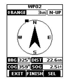
≑RANGE Bn
Range displays the radius of a compass circle
Push [▲] or [▼] to change the range between 0.125, 0.25, 0.5, 0.75, 1.5, 3, 6, and 12 nm.
N-UP
Displays the display's direction type. Push the software key below [SEL] to select "N-UP," "AC-UP," or "WP-UP." () See page 63 for details.

This flag icon indicates the direction to reach the target Waypoint or MOB waypoint.
- BIG 325 • Displays the bearing of the target Waypoint or MOB waypoint from your vessel.
- DIST 22.6m Displays the distance to the Waypoint or MOB waypoint.
- Displays the Course Over Ground.
- 50G 2.5 kt Displays the Speed Over Ground.
TIP : Once the navigation starts, it continues even if you close the Navigation screen by pushing the software key below [EXIT]. To properly finish the navigation, push the software key below [FINISH].
■ Compass
The Compass shows your vessel's Course Over Ground (COG) and Speed Over Ground (SOG).
- 1. Push [◀] or [▶] to display COMP.
-
Push the software key below COMP
- The "Compass" screen is displayed.
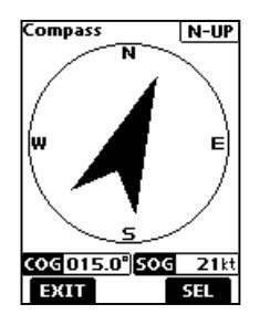
N-UP
Displays the display's direction type.
Push the software key below [SEL] to select "N-UP" or "AC-UP." (1) See page 63 for details.
COG 359°
Displays the Course Over Ground.
sog 2.5kt Displays the Speed Over Ground.
3. Push the software key below [EXIT] to close the "Compass" screen, and return to the operating screen.
■ GPS/GNSS
The GPS or GNSS "Status" screen displays the quantity, signal power, and position of the GPS satellites in the sky view. The screen also displays the direction, elevation angle, satellite numbers, and their received signal strength.
TIP : Use the transceiver outdoors so the receiver has a clear view to receive GPS signals from the satellites.
♦ GPS/GNSS Status screen Displaying the Status screen:
- Push [MENU]. The Menu screen is displayed.
- Push [▲] or [♥] to select "GPS," and then push [ENT]. The "GPS" screen is displayed
The "GPS" screen is displayed. () "GNSS" may be displayed, instead of "GPS" depending on the
of "GPS," depending on the transceiver version.
-
3. Push [▲] or [▼] to select "Status" and then push [ENT].
- The "Status" screen is displayed.
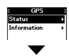
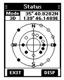
9 OTHER FUNCTIONS
GPS/GNSS Status screen (Continued) Sky view description:
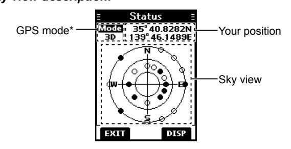
- * "2D" is displayed while tracking 3 or less satellites. "3D" is displayed while tracking more than 4 or more satellites.
- Push the software key below [DISP] to display the GPS/ GNSS status in the sky view or on the satellite signal strength status screen.
- Push the software key below [EXIT] to return to the operating screen.
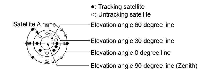
Image of the satellite
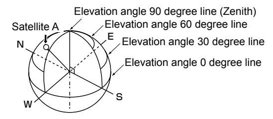
Satellite signal strength status description:
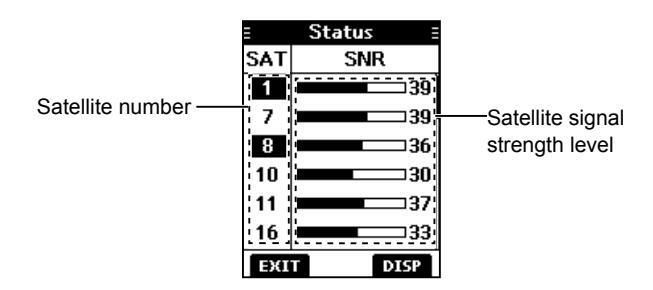

♦ GPS/GNSS Information screen Information screen description:
- Push [MENU]. The Menu screen is displayed.
- 2. Push [▲] or [▼] to select "GPS," and then push [ENT].
The "GPS" screen is displayed. "GNSS" may be displayed, instead of "GPS," depending on the transceiver version.
Push [▲] or [▼] to select "Information" and then push [ENT].
• The "Information" screen is displayed.
(1) The "Information" screen displays your position, date, time, Speed Over Ground (SOG), and Course
Over Ground (COG)
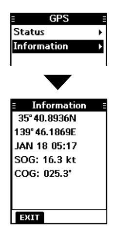
■ Information screen
You can check your transceiver's software version, GPS module version, and ATIS ID* on the "Information" screen. * Only for the Dutch and German versions.
- Push [MENU]. The Menu screen is displayed.
-
Push [▲] or [▼] to select "Information," and then push [ENT].
- The "Information" screen is displayed.
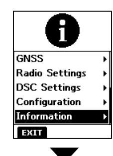
Push the software key below [EXIT] to return to the operating screen.
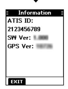
■ Using the Menu screen
The Menu screen is used to set items, select options, and so on for the transceiver's functions.
♦ Using the Menu screen
Example: Setting the channel group to "INT."
-
1. Push [MENU].
- The Menu screen is displayed
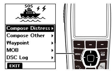
Push [▲] or [▼] to select "Radio Settings," and then push [ENT]. The "Radio Settings" screen is displayed. ①Holding down [▲] or [▼] sequentially scrolls up or down through the Menu
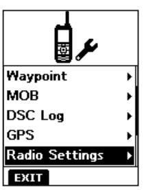
Push [▲] or [▼] to select "CHAN Group," and then push [ENT]. The "CHAN Group" screen is displayed.
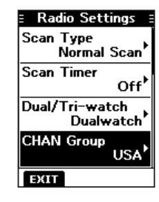
4. Push [▲] or [▼] to select "INT," and then push [ENT]. "INT" is set and the transceiver returns to the previous screen.
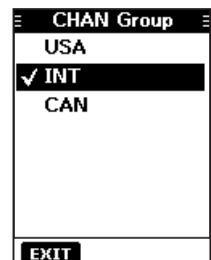
- To exit the Menu screen, push the software key below [EXIT].
- To return to the previous screen, push [CLR -0].
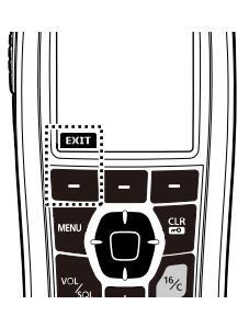
Menu screen items
The Menu screen contains the following items.
Compose Distress
| Item | Ref. | Item | Ref. |
|---|---|---|---|
| Undesignated | p. 23 | Sinking | p. 23 |
| Fire, Explosion | p. 23 | Adrift | p. 23 |
| Flooding | p. 23 | Abandoning Ship | p. 23 |
| Collision | p. 23 | Piracy | p. 23 |
| Grounding | p. 23 | Man Overboard | p. 23 |
| Capsizing | p. 23 | — | — |
Compose Other
| Item | Ref. | Item | Ref. |
|---|---|---|---|
| Individual Call | p. 25 | Polling Request | р. 35 |
| Group Call | p. 28 | Test Call | р. 29 |
| Position Request* | p. 33 | _ | _ |
Waypoint (See pages 52 ~ 54 for details) MOB (See page 51 for details)
DSC Log
| Item | Ref. | Item | Ref. |
|---|---|---|---|
| Received | p. 46 | Transmitted | p. 47 |
GPS/GNSS
| Item | Ref. | Item | Ref. |
|---|---|---|---|
| Status | p. 56 | Information | p. 58 |
Radio Settings
| ltem | Ref. | Item | Ref. |
|---|---|---|---|
| Scan Type* | p. 61 | Noise Cancel | p. 62 |
| Scan Timer* | p. 61 | Call Channel | p. 62 |
| Dual/Tri-watch* | p. 61 | FAV Settings | p. 62 |
| CHAN Group | p. 61 | RT Indicator | p. 62 |
| WX Alert* | p. 61 | CH Display | p. 62 |
| Monitor | p. 62 | — | — |
DSC Settings
| ltem | Ref. | Item | Ref. |
|---|---|---|---|
| Position Input | p. 48 | Unread Return | p. 49 |
| Individual ID | p. 48 | MOB Auto Set | p. 49 |
| Group ID | p. 48 | Alarm Status | p. 49 |
| Auto ACK | p. 48 | CH 70 SQL Level | p. 50 |
| CH Auto Switch | p. 48 | DST at PW Off | p. 50 |
| DSC Switch | p. 48 | Loop Test | p. 50 |
Configuration
| ltem | Ref. | Item | Ref. |
|---|---|---|---|
| Backlight | p. 63 | UTC Offset | р. 63 |
| Display Contrast | p. 63 | Inactivity Timer | p. 63 |
| Кеу Веер | p. 63 | Float'n Flash | p. 63 |
| Key Assignment | p. 63 | Power Save | p. 63 |
| Direction | p. 63 | — | — |
Information (See page 58 for details)
*May not be displayed, depending on the transceiver version.
Radio Settings items The default setting may differ, depending on the transceiver version
Scan Type
(Default: ----)
The transceiver has 2 scan types. Select Normal Scan and Priority Scan.
- Normal Scan: Scans all Favorite channels in the selected channel group.
- Priority Scan : Sequentially scans all Favorite channels, while monitoring Channel 16.
Scan Timer
(Default: Off)
You can use the Scan Timer to pause, or to resume after 5 seconds, when a signal is detected.
- On : When a signal is detected on a channel, the scan pauses for 5 seconds, and then resumes. If the signal disappears in less than 5 seconds, the scan immediately resumes.
- Off. When a signal is detected on a channel, the scan pauses until the signal disappears, and then resumes
Dual/Tri-watch
(Default: Dualwatch)
Select Dualwatch or Tri-watch
- Dualwatch : Monitors Channel 16 while receiving on another channel.
- Tri-watch : Monitors Channel 16 and the Call channel while receiving on another channel.
③See page 18 for details.
CHAN Group
(Default: ----)
Select the suitable channel group for your operating area. Select INT, USA, CAN, DSC, or ATIS depending on the transceiver version. (1) See page 12 for details.
WX Alert
(Default: Off)
For the USA, Australian, and Export versions, an NOAA broadcast station transmits a Weather Alert tone before any important weather information.
() "WX * " is displayed instead of "WX."
①"WX 🗣" blinks until you push a key after detecting an alert.
- On with Scan: The preset Weather channels are sequentially checked while scanning.
- On : The previously selected (last used) Weather channel is checked while scanning.
- Off: The Weather Alert tone is not detected.
- Monitor
(Default: Push)
Hold down [VOL/SQL] for 1 second to turn ON the Monitor function. The squelch opens.
You can select whether the squelch closes when you release [VOL/SQL], or when you push any key.
- Push : The squelch stays open while holding down [VOL/SQL].
- Hold : The squelch stays open until you push any key.
Noise Cancel
(Default: Off)
The Noise Cancel function reduces random noise components in the received or transmitted signal. Set the function for both receiving and transmitting.
RX
- Off: The Noise Cancel function is OFF.
- 1: Reduces random noise components in the received signal to approximately one half.
- 2: Reduces random noise components in the received signal to approximately one third.
- 3: Reduces random noise components in the received signal to approximately one tenth.
ТΧ
- On : Reduces random noise components in the transmitted signal to approximately one third.
- Off: The Noise Cancel function is OFF.
Call Chancel
(Default: —)
You can change your Call channel. The default setting differs, depending on the transceiver version. ①See page 13 for details.
FAV Settings
You can set all channels as Favorite channels, clear all settings, or reset to default. By default, some channels are preset. The Favorite channels differ, depending on the transceiver version.
- Set All Channels: Sets all channels as Favorite channels.
- Clear All Channels : Clears all Favorite channels.
- Set default: Resets Favorite channels to the default. (1) See page 17 for details.
RT Indicator
(Default: On)
Select whether or not to display the Radio Telephone indicator (RT) while in the RT mode. This indicates that while RT is displayed, you can make a voice communication, except for a DSC call.
- On: The RT indicator is displayed.
- Off: The RT indicator is not displayed.
- (1) When "On" is selected, "STBY" is displayed while in the standby mode, and "DSC" is displayed while in the DSC mode.
CH Display
(Default: 4 Digits)
You can select the number of digits to display the channel number.
- 3 Digits: The channel number is displayed in 3 digits, such as "01A."
- 4 Digits : The channel number is displayed in 4 digits, such as "1001."
- This setting may not be usable, depending on the presetting.
Backlight
You can adjust the backlight brightness between 1 and 7, or OFF. The backlight automatically turns OFF after no key is pushed for 5 seconds.
Continue Type
You can set the backlight on dim, even if the backlight is automatically turned OFF. This function enables you to see the display in the dark, even when the backlight is OFF.
- Off: The function is turned OFF
- Dim: The screen stavs dimly lit, even if the backlight is turned OFF after no key is pushed for 5 seconds.
① If you want to reduce the battery consumption, turn this function
Display Contrast
(Default: 4)
You can adjust the display contrast level between 1 and 8. One is the lowest contrast level, and eight is the highest contrast level
Key Been
You can select whether or not to sound a beep when a key is pushed
- On: Sounds a beep when a key is pushed.
- Off: No beep sounds, for silent operation
Kev Assignment
The default setting may differ, depending on the transceiver version
Softkey 1~21
You can change which software key functions to display, and their order. You can assign up to 21 software keys at a time.
The usable software key functions and their order may differ, depending on the transceiver version
Select this item to set the software key function order as dofoult
Direction
You can set the display type for the "Compass." "Navigation." and "Position Check" screen
Compass
(Default: N-UP)
- N-UP : The top of the compass represents North.
- AC-UP: The compass represents the direction of your course heading
Navigation
- (Default: N-UP)
- N-UP : The top of the "Navigation" screen represents North.
- AC-UP: The top of the "Navigation" screen represents the direction of your course heading
- WP-UP: The top of the "Navigation" screen represents the destination waypoint.
10 MENU SCREEN
Configuration items
(Default: 4)
Position Check
(Default: N-UP)
- N-UP : The top of the "Position Check" screen represents North.
- AC-UP : The top of the "Position Check" screen represents the direction of your course heading.
UTC Offset
(Default: 00:00)
Set the offset time between Universal Time Coordinated (UTC) and your local time to between –14:00 and +14:00 (in 1 minute steps).
Inactivity Timer
The transceiver automatically returns to the operation screen if you push no key for the set period of time for each mode.
Not DSC Related
(Default: 10 min)
This setting is for when the transceiver displays a screen that is not related to DSC.
DSC Related
(Default: 15 min)
This setting is for when the transceiver displays a screen that is related to DSC.
Distress Related
(Default: Off)
This setting is for when the transceiver displays a screen that is related to a Distress call.
RT Related
(Default: 30 sec)
This setting is for when the transceiver is in the Radio Telephone mode.
Float'n Flash
The Elect's Elect function detects that the transceiver has come in contact with water. When the function turns ON, the backlight starts to blink to make it easy to find the transceiver, even in the dark (Default: On) • On: The Election Electric function is ON • Off The Fleat's Flash function is OFF (Default: 20 sec) After taking the transceiver out of the water, the backlight keeps blinking for this set period of time. Set the time to between 0 and 30 seconds (in 10 second steps). Cvcle The backlight repeatedly turns ON or OFF in the set time cycle. Set the cycle to 0.5, 1, 2 or 4 seconds. Alarm (Default: Off) Select whether or not to sound an alarm while the backlight blinke when the Elect's Elech function is turned ON • On : An alarm sounds while the backlight blinks. • Off: No alarm sounds, even when the Float'n Flash function is set to ON Power Save (Default: On) The Power Save function reduces the current drain by
deactivating the receiver circuit of the transceiver at specified intervals. When this setting is ON, the function automatically starts the battery conserve when no signal is received for 5 seconds.
11 BATTERY CHARGING
♦ Battery caution
Misuse of Li-ion batteries may result in the following hazards: smoke, fire, or the battery may rupture. Misuse can also cause damage to the battery or degradation of battery's performance.
▲ DANGER! NEVER solder the battery terminals, or NEVER modify the battery pack. This may cause heat generation, and the battery may burst, emit smoke or catch fire.
▲ DANGER! NEVER leave battery pack in places with temperatures above +60°C (+140°F). High temperature buildup in the battery, such as could occur near fires or stoves, inside a sun-heated vehicle, or in direct sunlight for long periods of time may cause the battery to rupture or catch fire. Excessive temperatures may also degrade battery's performance or shorten battery life.
▲ DANGER! NEVER strike or otherwise impact the battery. Do not use the battery if it has been severely impacted or dropped, or if the battery has been subjected to heavy pressure. Battery damage may not be visible on the outside of the case. Even if the surface of the battery does not show cracks or any other damage, the cells inside the battery may rupture or catch fire.
▲ DANGER! NEVER expose the battery to rain, snow, seawater, or any other liquids. Do not charge or use a wet battery. If the battery gets wet, be sure to wipe it dry before using.
△ DANGER! NEVER place or leave battery packs near fire. Fire or heat may cause them to rupture or explode. Dispose of used battery packs in accordance with local regulations.
▲ DANGER! NEVER use the battery with a transceiver for which it is not specified. Never use a battery with any other equipment, or for any purpose that is not specified in this instruction manual.
▲ DANGER! NEVER let fluid from inside the battery get in your eyes. If it does, blindness can result. Rinse your eyes with clean water, without rubbing them, and immediately go to a doctor.
▲ WARNING! NEVER put the battery in a microwave oven, high-pressure container, or in an induction heating cooker. This could cause a fire, overheating, or cause the battery to rupture.
▲ WARNING! NEVER use the battery if it emits an abnormal odor, heats up, or is discolored or deformed. If any of these conditions occur, contact your lcom dealer or distributor.
△ WARNING! NEVER use deteriorated battery packs. They could cause a fire.
△ WARNING! NEVER let fluid from inside the battery come in contact with your body. It it does, immediately wash with clean water.
CAUTION: DO NOT use the battery pack out of the specified temperature range.
|
−20°C ~ +60°C (−4°F ~ +140°F) |
|---|---|
| • IC-M93D EURO: | –15°C ~ +55°C |
| (-10°C ~ +55°C for the Australian version) | |
| • BP-285: | −20°C ~ +60°C (−4°F ~ +140°F) |
Using the battery out of its specified temperature range will reduce the battery's performance and battery life. Please note that the specified temperature range of the battery may exceed that of the transceiver. In such cases, the transceiver may not work properly because it is out of its operating temperature range.
BATTERY CHARGING 11
CAUTION: Shorter battery life could occur if the battery is left fully charged, completely discharged, or in an excessive temperature environment (above +50°C (+122°F)) for an extended period of time. If the battery pack must be left unused for a long time, it must be detached from the transceiver after discharging. You may use the battery pack until the remaining capacity is about half, then keep it safely in a cool and dry place at the following temperature range: -20°C ~ +50°C (-4°F ~ +122°F) (within a month) -20°C ~ +40°C (-4°F ~ +104°F) (within three months) -20°C ~ +20°C (-4°F ~ +68°F) (within a year)
BE SURE to replace the battery pack with a new one approximately five years after manufacturing, even if it still holds a charge. The inside battery material will become weak after a period of time, even with little use. The estimated number of times you can charge the battery is between 300 and 500. Even when the battery appears to be fully charged, the operating time of the transceiver may become short when: Approximately five years have passed since the battery was manufactured.
• The battery has been repeatedly charged.
♦ Charging caution
▲ DANGER! NEVER charge the battery pack in areas with extremely high temperatures, such as near fires or stoves, inside a sun-heated vehicle, or in direct sunlight. In such environments, the safety/protection circuit in the battery will activate, causing the battery to stop charging.
△ DANGER! NEVER charge the transceiver during a lightning storm. It may result in an electric shock, cause a fire or damage the transceiver. Always disconnect the power adapter before a storm.
▲ WARNING! NEVER charge or leave the battery in the battery charger beyond the specified time for charging. If the battery is not completely charged by the specified time, stop charging and remove the battery from the battery charger. Continuing to charge the battery beyond the specified time limit may cause a fire, overheating, or the battery may rupture.
▲ WARNING! Occasionally observe the battery pack condition while charging. If any abnormal condition occurs, discontinue using the battery pack.
▲ WARNING! NEVER insert the transceiver (battery attached to the transceiver) into the charger if it is wet or soiled. This could corrode the battery charger terminals or damage the charger. The charger is not waterproof.
CAUTION: DO NOT use the power adapter unless the power outlet is easily accessible and near the unit. Remove it from the power outlet when not in use.
NOTE: Charge the battery pack within the specified temperature range: +10°C ~ +45°C (+50°F ~ +113°F). Otherwise, the charging time will be longer, but the battery will not reach a full charge. While charging, at a point after the temperature goes out of the specified range, the charging will automatically stop.
NOTE: Be sure the slots on the battery pack are correctly aligned
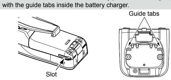
11 BATTERY CHARGING
■ Regular battery charger
♦ Installing the BC-220
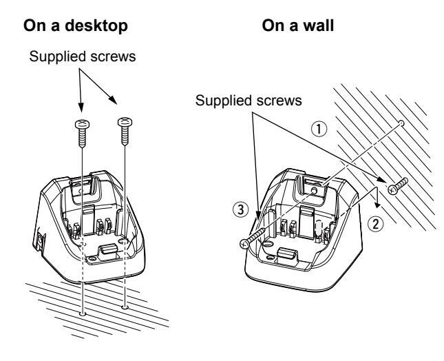
♦ Charging with the BC-220 and BC-123S
You can charge Li-ion battery pack using the BC-220 and BC-123S.
• Charging time: approximately 3 hours.
①You can also use the CP-25H CIGARETTE LIGHTER CABLE, or OPC-515L DC POWER CABLE instead of the BC-123S.
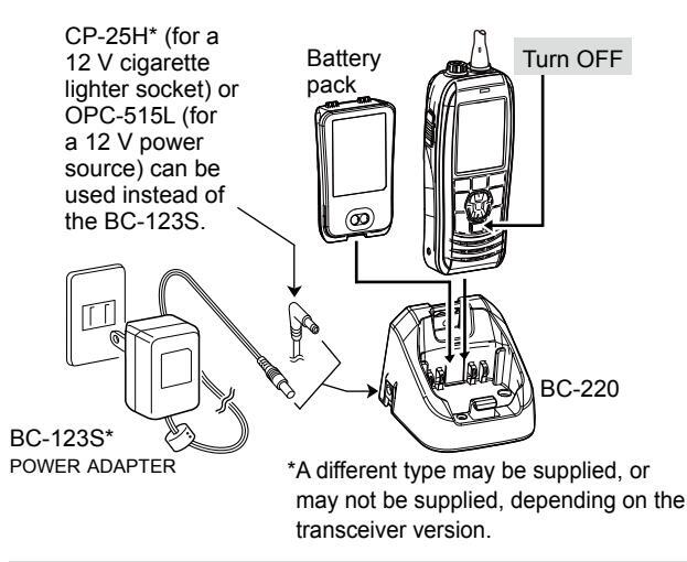
CAUTION: NEVER connect the OPC-515L to a power source using reverse polarity. This will damage the battery charger.
White line:
Optional battery charger
♦ Rapid charging with the BC-214, BC-157S and AD-133
The optional BC-214 with the BC-157S and AD-133 simultaneously charges up to 6 Li-ion battery packs.
Charging time: approximately 3 hours.
(1) You can also use the OPC-656* DC POWER CABLE instead of the BC-157S and AD-133.
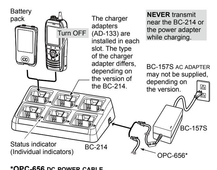
Connect to a DC power source (12 ~ 16 V/at least 7 A)
CAUTION: NEVER reverse the polarity when connecting the power cable to a power source. This will damage the battery charger. Red line: ⊕ / Black line: ⊖
12 OPTIONAL SPEAKER MICROPHONE
■ About the HM-165
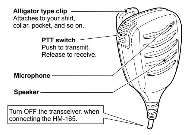
NOTE
- NEVER immerse the connector in water. If the connector becomes wet, be sure to dry it BEFORE connecting it to the transceiver.
- If the audio sound becomes muffled, remove any water that may be inside the speaker grill and/or microphone hole.
- The microphone is near the top of the speaker microphone. To maximize the readability of your transmitted signal, hold the microphone 5 to 10 cm (2 to 4 inches) from your mouth, and then speak at your normal voice level. The DSC alarms sound from the transceiver even while
- The DSC alarms sound from the transceiver, even while the speaker microphone is attached.
■ Attaching the HM-165
- 1. Turn OFF the transceiver.
- Insert the speaker microphone into the connector, and then screw it tight, as shown below. ①Be careful not to cross-thread the connection.
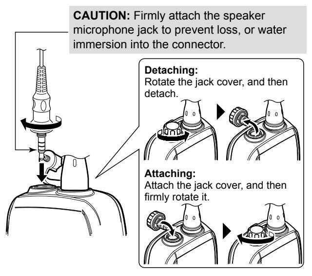
NOTE: KEEP the jack cover attached when the speakermicrophone is not connected. Otherwise, water will get into the transceiver, and the terminals will become rusty, or if the connector gets wet, the transceiver may not work properly.
TROUBLESHOOTING 13
| PROBLEM | POSSIBLE CAUSE | SOLUTION | REF. |
|---|---|---|---|
| You cannot turn ON the transceiver. |
|
Recharge the battery pack. | p. 67 |
| • The Battery pack is not correctly attached. |
|
p. 2 | |
| Little or no sound comes from the |
|
|
p. 13 |
| speaker. | • The speaker has been exposed to water. |
|
p. 15 |
|
Dry the speaker microphone connector. | _ | |
| You cannot transmit |
|
Change channels. | p. 14 |
|
|
p. 67 | |
| The output power is set to low. |
|
p. 5 | |
| Scan does not start |
|
Set the Favorite channels. | р. 17 |
| No beeps sound | • Key Beep is set to OFF. |
|
p. 63 |
| You cannot send DSC calls |
|
|
р. 9
р. 48 |
|
You cannot receive
GPS position data |
• The built-in GPS antenna is obstructed,
which interrupts the GPS signals from the satellites. |
|
_ |
14 SPECIFICATIONS AND OPTIONS
TY 156 025 ~ 157 425 MHz
RX 156 050 ~ 163 275 MHz
Tx (5 W) 1 5 A
Tx (1 W) 0.7 A
50 O nominal
+10 nnm
EM (16K0G3E) DSC (16K0G2B)
RX maximum audio 0.25 A (External)
7.2 V DC nominal (negative ground)
57 (W) × 144 6 (H) × 38 5 (D) mm
2.2 (W) × 5.7 (H) × 1.5 (D) inches
0 45 A (Internal)
-20°C ~ +60°C (-4°F ~ +140°F)
Specifications
Mossurements made without an antenna
IC-M93D
♦ General
• Frequency coverage:
Operating temperature range: • Current drain (approximate)
- Power supply requirement Frequency stability: Antenna impedance: • Dimensions (approximate): (Projections not included)
- Weight (approximate)
♦ Transmitter
• Output power: Modulation system
Adjacent channel power:
Variable reactance frequency Maximum frequency deviation • Spurious emissions (typical) 60 400
265 g/9 3 oz with BP-285
Sensitivity (typical): 0.25 µV (12 dB SINAD) Squelch sensitivity (threshold_typical): 0.25 µV
Intermodulation rejection ratio: 70 dB (typical) Spurious response rejection ratio: 70 dB (typical) ·Adjacent channel selectivity: 70 dB (typical) • Audio output power (at 10% distortion)
0.35 W typical (External) with an 9 O load 0.9 W typical (Internal) with a
IC-MOSD FURO
Frequency coverage:
- Mode
- Operating temperature range:
- Current drain (approximate):
Power supply requirement
Frequency stability:
Antenna impedance:
• Weight (approximate)
Px 156 000 ~ 163 425 MHz FM (16K0G3F) DSC (16K0G2B) _15°C ~ +55°C TX (5 W) 1 5 A TX (1 W) 0.7 A RX maximum audio 0 25 A (External) 0 45 A (Internal) 7.2 V DC nominal (negative ground) 50 O nominal 57 (W) × 144 6 (H) × 38 5 (D) mm
Dimensions (approximate) (Projections not included)
265 a with BP-285
SPECIFICATIONS AND OPTIONS 14
7.2 V DC nominal (negative ground)
57 (W) × 144.6 (H) × 38.5 (D) mm
±10 ppm (-10°C ~ +55°C)
265 g/9.3 oz with BP-285
♦ Transmitter
Output nower:
- SAR 10a
- Modulation system:
Spurious emissions:
Adjacent channel power:
Variable reactance frequency Maximum frequency deviation: 0.25 uW
-6 dBµ emf at 20 dB SINAD Sensitivity (typical): Squelch sensitivity (threshold, typical): 6 dDu omf Intermodulation rejection ratio: Sourious response rejection ratio: 70 dB Adjacent channel selectivity: Audio output power (at 10% distortion) 0.9 W typical (Internal) with a
IC-M93D EURO (Australian version) TX 156 025 ~ 157 425 MHz
• Frequency coverage:
• Mode
Operating temperature range · Current drain (approximate):
DX 156 300 ~ 162 025 MHz FM (16K0G3E), DSC (16K0G2B) 10°C ~ ±55°C TX (1 W) 0.7 A DX maximum audia 0.25 A (External)
Power supply requirement: • Frequency stability: Antenna impedance: Dimensions (approximate): (Projections not included)
• Weight (approximate):
| Output power: | 5 W/1 W |
|---|---|
|
Variable reactance frequency |
| modulation | |
| Maximum frequency deviation: | ±5.0 kHz |
|
70 dB |
|
0.25 μW |
♦ Receiver
Sensitivity (typical): -6 dBu emf (20 dB SINAD) Squelch sensitivity (threshold, typical): -6 dRu emf 65 dB Intermodulation rejection ratio: Spurious response rejection ratio: 65 dE Adjacent channel selectivity •Audio output power (at 10% distortion): 0.2 W (External) with an 8 O load
0.9 W typical (Internal) with a
14 SPECIFICATIONS AND OPTIONS

♦ Battery pack
• BP-285 Li-ion BATTERY PACK
| Battery pack | Voltage | Capacity | Battery life* |
|---|---|---|---|
| BP-285 | 7.2 V |
1485 mAh (minimum)
1570 mAh (typical) |
9 hours |
* The operating periods are calculated under the following conditions; TX : RX : Standby = 5 : 5 : 90
(Power save : ON)
♦ Chargers
• BC-220 RAPID CHARGER + BC-123S AC ADAPTER For rapid charging of battery pack.
(Charging time: approximately 3 hours)
• BC-214 RAPID CHARGER + AD-133 CHARGER ADAPTER (6 pcs.)
+ BC-157S AC ADAPTER
For rapid charging of 6 battery packs.
(Charging time: approximately 3 hours)
♦ DC cables
• OPC-515L/OPC-656 DC POWER CABLE For charging of the battery packs using a 12 V DC power source instead of the AC adapter. (OPC-515L for BC-220 : OPC-656 for BC-214)
♦ Other
• HM-165/HM-228 SPEAKER MICROPHONE
Full sized waterproof speaker microphone including alligator type clip to attach to your shirt or collar.
- FA-SC59V FLEXIBLE ANTENNA
- MB-133 BELT CLIP
- MB-96F/MB-96FL LEATHER BELT HANGER
- CP-25H CIGARETTE LIGHTER CABLE For charging with the BC-220 charger through a 12 V cigarette lighter socket.
NOTE: The CP-25H is equipped with a 1 A fuse. If the fuse blows, repair the problem, then replace it with a new rated fuse. DO NOT use fuses with amp ratings other than the ratings written below.
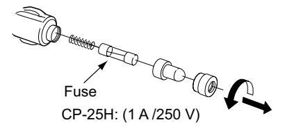
CHANNEL LIST 15
♦ For IC-M93D and IC-M93D EURO (Australia)
| Chan | nel nu | mber | Frequen | С | |
|---|---|---|---|---|---|
| USA | INT | CAN | Transmit | Receive | U |
| 01 | 01 | 156.050 | 160.650 | ||
| 1001 | 1001*4 | 156.050 | 156.050 | ||
| 02 | 02 | 156.100 | 160.700 | 1 | |
| 03 | 03 | 156.150 | 160.750 | ||
| 04 | 156.200 | 160.800 | |||
| 1004 | 156.200 | 156.200 | 1 | ||
| 05 | 156.250 | 160.850 | |||
| 1005 | 1005*4 | 1005 | 156.250 | 156.250 | 1 |
| 06 | 06 | 06 | 156.300 | 156.300 | |
| 07 | 156.350 | 160.950 | |||
| 1007 | 1007*4 | 1007 | 156.350 | 156.350 | |
| 08 | 08 | 08 | 156.400 | 156.400 | |
| 09 | 09 | 09 | 156.450 | 156.450 | |
| 10 | 10 | 10 | 156.500 | 156.500 | |
| 11 | 11 | 11 | 156.550 | 156.550 | |
| 12 | 12 | 12 | 156.600 | 156.600 | |
| 13* 1 | 13 | 13* 1 | 156.650 | 156.650 | |
| 14 | 14 | 14 | 156.700 | 156.700 | |
| 15* 3 | 15* 2 | 15* 1 | 156.750 | 156.750 | |
| 16 | 16 | 16 | 156.800 | 156.800 | |
| 1 7* 1 | 17 | 1 7*1 | 156.850 | 156.850 | |
| 18 | 156.900 | 161.500 | |||
| 1018 | 1018*4 | 1018 | 156.900 | 156.900 | |
| 19 | 156.950 | 161.550 | |||
| 1019 | 1019 | 1019 | 156.950 | 156.950 | 1 |
| 2019 | RX only | 161.550 | |||
| 20 | 20 | 20*1 | 157.000 | 161.600 | |
| 1020 | 1020 | 157.000 | 157.000 |
| ( | , | ||||||
|---|---|---|---|---|---|---|---|
| Chan | nel nu | mber | Frequency (MHz) | ||||
| USA | INT | CAN | Transmit | Receive | |||
| 2020 | RX only | 161.600 | |||||
| 21 | 157.050 | 161.650 | |||||
| 1021 | 1021*4 | 1021 | 157.050 | 157.050 | |||
| 2021 | RX only | 161.650 | |||||
| 22 | 157.100 | 161.700 | |||||
| 1022 | 1022*4 | 1022 | 157.100 | 157.100 | |||
| 23 | 23 | 157.150 | 161.750 | ||||
| 1023 | 1023*4 | 157.150 | 157.150 | ||||
| 2023 | RX only | 161.750 | |||||
| 24 | 24*5 | 24 | 157.200 | 161.800 | |||
| 25 | 25*5 | 25 | 157.250 | 161.850 | |||
| 2025 | RX only | 161.850 | |||||
| 26 | 26*5 | 26 | 157.300 | 161.900 | |||
| 27 | 27 | 27 | 157.350 | 161.950 | |||
| 1027*4 | 157.350 | 157.350 | |||||
| 28 | 28 | 28 | 157.400 | 162.000 | |||
| 1028*4 | 157.400 | 157.400 | |||||
| 2028 | RX only | 162.000 | |||||
| 60 | 60 | 156.025 | 160.625 | ||||
| 61 | 156.075 | 160.675 | |||||
| 1061 | 156.075 | 156.075 | |||||
| 62 | 156.125 | 160.725 | |||||
| 1062 | 156.125 | 156.125 | |||||
| 63 | 156.175 | 160.775 | |||||
| 1063 | 1063*4 | 1063 | 156.175 | 156.175 | |||
| 64 | 64 | 156.225 | 160.825 | ||||
| 1064 | 156.225 | 156.225 | |||||
| 65 | 156.275 | 160.875 | |||||
| Chan | nel nu | mber | Frequency (MHz) | |||
|---|---|---|---|---|---|---|
| USA | INT | CAN | Transmit | Receive | ||
| 1065 | 1065*4 | 1065*1 | 156.275 | 156.275 | ||
| 66 | 156.325 | 160.925 | ||||
| 1066 | 1066*4 | 1066*1 | 156.325 | 156.325 | ||
| 67* 1 | 67 | 67 | 156.375 | 156.375 | ||
| 68 | 68 | 68 | 156.425 | 156.425 | ||
| 69 | 69 | 69 | 156.475 | 156.475 | ||
| 71 | 71 | 71 | 156.575 | 156.575 | ||
| 72 | 72 | 72 | 156.625 | 156.625 | ||
| 73 | 73 | 73 | 156.675 | 156.675 | ||
| 74 | 74 | 74 | 156.725 | 156.725 | ||
| 75* 2 | 75* 1 | 156.775 | 156.775 | |||
| 76* 2 | 76* 1 | 156.825 | 156.825 | |||
| 77* 1 | 77 | 77* 1 | 156.875 | 156.875 | ||
| 78 | 156.925 | 161.525 | ||||
| 1078 | 1078 | 1078 | 156.925 | 156.925 | ||
| 2078 | RX only | 161.525 | ||||
| 79 | 156.975 | 161.575 | ||||
| 1079 | 1079 | 1079 | 156.975 | 156.975 | ||
| 2079 | RX only | 162.575 | ||||
| 80 | 157.025 | 161.625 | ||||
| 1080 | 1080*4 | 1080 | 157.025 | 157.025 | ||
| 81 | 157.075 | 161.675 | ||||
| 1081 | 1081*4 | 1081 | 157.075 | 157.075 | ||
| 82 | 157.125 | 161.725 | ||||
| 1082 | 1082*4 | 1082 | 157.125 | 157.125 | ||
| 83 | 157.175 | 161.775 | ||||
| 1083 | 1083*4 | 1083 | 157.175 | 157.175 | ||
| 2083 | RX only | 161.775 | ||||
| Chan | nel nu | mber | Frequency (MHz) | ||||
|---|---|---|---|---|---|---|---|
| USA | INT | CAN | Transmit | Receive | |||
| 84 | 84*5 | 84 | 157.225 | 161.825 | |||
| 85 | 85*5 | 85 | 157.275 | 161.875 | |||
| 86 | 86*5 | 86 | 157.325 | 161.925 | |||
| 87 | 87 | 87 | 157.375 | 157.375 | |||
| 88 | 88 | 88 | 157.425 | 157.425 | |||
| WX channel | Frequen | cy (MHz) | ||
|---|---|---|---|---|
| WA Channel | Transmit | Receive | ||
| 1 | RX only | 162.550 | ||
| 2 | RX only | 162.400 | ||
| 3 | RX only | 162.475 | ||
| 4 | RX only | 162.425 | ||
| 5 | RX only | 162.450 | ||
| 6 | RX only | 162.500 | ||
| 7 | RX only | 162.525 | ||
| 8 | RX only | 161.650 | ||
| 9 | RX only | 161.775 | ||
| 10 | RX only | 163.275 | ||
• Simplex channels 1021 1023 Simplex channels, 1021, 1023, 1081, 1082, and 1083 CANNOT be lawfully used by the general public in USA waters When the "CH Display" setting in the Menu screen is set to "3 Digits " the channel number is displayed in 3 digits (For example
"1001" is displayed as "01A.")
*1 Low power only. *2 Low power only (Except for the AUS version). *3 BX only. *4 For only the USA and EXP version
*5 For only the AUS version.
15 CHANNEL LIST
♦ For IC-M93D EURO
International channels
| Frequen | cy (MHz) | Frequen | cy (MHz) | Frequen | cy (MHz) | Frequen | cy (MHz) | Frequen | cy (MHz) | Frequen | cy (MHz) | Frequen | cy (MHz) | |||||||
|---|---|---|---|---|---|---|---|---|---|---|---|---|---|---|---|---|---|---|---|---|
| СН | Transmit | Receive | СН | Transmit | Receive | СН | Transmit | Receive | СН | Transmit | Receive | СН | Transmit | Receive | СН | Transmit | Receive | СН | Transmit | Receive |
| 01 | 156.050 | 160.650 | 11 | 156.550 | 156.550 | 2019 | RX Only | 161.550 | 27 | 157.350 | 161.950 | 66 | 156.325 | 160.925 | 77 | 156.875 | 156.875 | 83 | 157.175 | 161.775 |
| 02 | 156.100 | 160.700 | 12 | 156.600 | 156.600 | 20 | 157.000 | 161.600 | 28 | 157.400 | 162.000 | 67 | 156.375 | 156.375 | 78 | 156.925 | 161.525 | 84 | 157.225 | 161.825 |
| 03 | 156.150 | 160.750 | 13 | 156.650 | 156.650 | 1020 | 157.000 | 157.000 | 31*1/3 | 157.550 | 162.150 | 68 | 156.425 | 156.425 | 1078 | 156.925 | 156.925 | 85 | 157.275 | 161.875 |
| 04 | 156.200 | 160.800 | 14 | 156.700 | 156.700 | 2020 | RX Only | 161.600 | 1037*2 | 157.850 | 157.850 | 69 | 156.475 | 156.475 | 2078 | RX Only | 161.525 | 86 | 157.325 | 161.925 |
| 05 | 156.250 | 160.850 | 15* 1 | 156.750 | 156.750 | 21 | 157.050 | 161.650 | 60 | 156.025 | 160.625 | 71 | 156.575 | 156.575 | 79 | 156.975 | 161.575 | 87 | 157.375 | 157.375 |
| 06 | 156.300 | 156.300 | 16 | 156.800 | 156.800 | 22 | 157.100 | 161.700 | 61 | 156.075 | 160.675 | 72 | 156.625 | 156.625 | 1079 | 156.975 | 156.975 | 88 | 157.425 | 157.425 |
| 07 | 156.350 | 160.950 | 17* 1 | 156.850 | 156.850 | 23 | 157.150 | 161.750 | 62 | 156.125 | 160.725 | 73 | 156.675 | 156.675 | 2079 | RX Only | 161.575 | P4*4 | 161.425 | 161.425 |
| 08 | 156.400 | 156.400 | 18 | 156.900 | 161.500 | 24 | 157.200 | 161.800 | 63 | 156.175 | 160.775 | 74 | 156.725 | 156.725 | 80 | 157.025 | 161.625 | |||
| 09 | 156.450 | 156.450 | 19 | 156.950 | 161.550 | 25 | 157.250 | 161.850 | 64 | 156.225 | 160.825 | 75* 1 | 156.775 | 156.775 | 81 | 157.075 | 161.675 | |||
| 10 | 156.500 | 156.500 | 1019 | 156.950 | 156.950 | 26 | 157.300 | 161.900 | 65 | 156.275 | 160.875 | 76* 1 | 156.825 | 156.825 | 82 | 157.125 | 161.725 |
*1 Low power only.
*2 For only the HOL and UK version (UK Marina Channel: M1=1037 (157.850 MHz) for U.K. version), and low power only for the HOL version.
*3 For only the HOL version.
*4 UK Marina Channel: M2=P4 (161.425 MHz) for U.K. version only.
CHANNEL LIST 15
♦ For IC-M93D EURO
• USA channels (for UK version only)
| Frequen | cy (MHz) | Frequence | cy (MHz) | Frequen | cy (MHz) | Frequen | cy (MHz) | 011 | Frequen | cy (MHz) | ||||
|---|---|---|---|---|---|---|---|---|---|---|---|---|---|---|
| СП | Transmit | Receive | Transmit | Receive | СП | Transmit | Receive | СП | Transmit | Receive | Сп | Transmit | Receive | |
| 1001 | 156.050 | 156.050 | 15 | RX only | 156.750 | 25 | 157.250 | 161.850 | 71 | 156.575 | 156.575 | 84 | 157.225 | 161.825 |
| 1005 | 156.250 | 156.250 | 16 | 156.800 | 156.800 | 26 | 157.300 | 161.900 | 72 | 156.625 | 156.625 | 85 | 157.275 | 161.875 |
| 06 | 156.300 | 156.300 | 17* | 156.850 | 156.850 | 27 | 157.350 | 161.950 | 73 | 156.675 | 156.675 | 86 | 157.325 | 161.925 |
| 1007 | 156.350 | 156.350 | 1018 | 156.900 | 156.900 | 28 | 157.400 | 162.000 | 74 | 156.725 | 156.725 | 87 | 157.375 | 157.375 |
| 08 | 156.400 | 156.400 | 1019 | 156.950 | 156.950 | 1037 | 157.850 | 157.850 | 77* | 156.875 | 156.875 | 88 | 157.425 | 157.425 |
| 09 | 156.450 | 156.450 | 20 | 157.000 | 161.600 | 1063 | 156.175 | 156.175 | 1078 | 156.925 | 156.925 | P4 | 161.425 | 161.425 |
| 10 | 156.500 | 156.500 | 1020 | 157.000 | 157.000 | 1065 | 156.275 | 156.275 | 1079 | 156.975 | 156.975 | |||
| 11 | 156.550 | 156.550 | 1021 | 157.050 | 157.050 | 1066 | 156.325 | 156.325 | 1080 | 157.025 | 157.025 | |||
| 12 | 156.600 | 156.600 | 1022 | 157.100 | 157.100 | 67* | 156.375 | 156.375 | 1081 | 157.075 | 157.075 | |||
| 13* | 156.650 | 156.650 | 1023 | 157.150 | 157.150 | 68 | 156.425 | 156.425 | 1082 | 157.125 | 157.125 | |||
| 14 | 156.700 | 156.700 | 24 | 157.200 | 161.800 | 69 | 156.475 | 156.475 | 1083 | 157.175 | 157.175 |
* Low power only.
NOTE: Simplex channels, 1021, 1023, 1081, 1082, and 1083 CANNOT be lawfully used by the general public in USA waters.
15
16 SAFETY TRAINING INFORMATION

Your Icom radio generates RF electromagnetic energy while transmitting. This radio is designed for and classified as for "Occupational Use Only." This means it must be used only during the course of employment by individuals aware of the hazards, and the ways to minimize such hazards. This radio is NOT intended for use by the "General Population"
and complies with the FCC and IC RF exposure limits for "Occupational Use Only". In addition, your Icom radio complies with the following Standards and Guidelines with regard to RF energy and electromagnetic energy levels and evaluation of such levels for exposure to humans:
- FCC KDB Publication 447498 D03, Evaluating Compliance with FCC Guidelines for Human Exposure to Radio Frequency Electromagnetic Fields.
- American National Standards Institute (C95.1-1992), IEEE Standard for Safety Levels with Respect to Human Exposure to Radio Frequency Electromagnetic Fields. 3 kHz to 300 GHz.
- American National Standards Institute (C95.3-1992), IEEE Recommended Practice for the Measurement of Potentially Hazardous Electromagnetic Fields– RF and Microwave.
- The antennas, batteries, belt clips, speaker microphone, and other accessories that are listed in "OPTIONS" are authorized for use with this product. Use of accessories other than those specified may result in RF exposure levels exceeding the FCC and IC requirements for wireless RF exposure.; Belt Clip (MB-133), Rechargeable Li-ion Battery Pack (BP-285). Health Canada Safety Code 6 - Limits of Human Exposure to
- Electromagnetic Energy in the Frequency Range from 3 kHz to 300 GHz.

To ensure that your expose to RF electromagnetic energy is within the FCC and IC allowable limits for occupational use, always adhere to the following guidelines:
- DO NOT operate the radio without a proper antenna attached, as this may damage the radio and may also cause you to exceed FCC and IC RF exposure limits. A proper antenna is the antenna supplied with this radio by the manufacturer or an antenna specifically authorized by the manufacturer for use with this radio.
- DO NOT transmit for more than 50% of the total radio use time ("50% duty cycle"). Transmitting more than 50% of the time can cause FCC and IC RF exposure compliance requirements to be exceeded. The radio is transmitting when the TX icon is displayed. You can cause the radio to transmit by pushing the "PTT" switch.
- ALWAYS keep the antenna at least 2.5 cm (1 inch) away from the body when transmitting, and only use the Icom belt-clips listed in "OPTIONS" when attaching the radio to your belt, or other place, to ensure FCC and IC RF exposure compliance requirements are not exceeded.
The information listed above provides the user with the information needed to make him or her aware of RF exposure, and what to do to assure that this radio operates within the FCC and IC RF exposure limits of this radio.
Electromagnetic Interference/Compatibility
During transmissions, your Icom radio generates RF energy that can possibly cause interference with other devices or systems. To avoid such interference, turn off the radio in areas where signs are posted to do so. DO NOT operate the transmitter in areas that are sensitive to electromagnetic radiation such as hospitals, aircraft, and blasting sites.
INDEX
| А | |
|---|---|
| Accessories | ; |
| Alarm Status (DSC Settings) | 49 |
| All Ships call | |
| Receiving | 4: |
| AquaQuake Water Draining function | 1: |
| ATIS ID | |
| Auto ACK, DSC Settings | 4 |
| В | |
| Backlight (Configuration) | 6 |
| Battery | |
| Charger, optional | 6 |
| Charger, regular | 6 |
| Battery indicator | |
| Installing/charging | 6 |
| С | |
| Call Channel | |
| Radio Settings | 6 |
| Selecting | 1 |
| Setting | 1 |
| CH 70 SQL Level | |
| (DSC Settings) | 5 |
| CHAN Group, Radio Settings | 6 |
| Channel | |
| Favorite | 1 |
| Group | 1: |
| List | 74 |
| Name, editing | 1 |
| Selecting | 1 |
| Channel 16 | 1 . |
| CH Auto Switch (DSC Settings) | 4 |
| CH Display (Radio Settings) | |
|---|---|
| Compass | |
| Configuration items | 63 |
| D | |
| Direction (Configuration) | 63 |
| Display | |
| Contrast (Configuration) | 63 |
| Description | 5 |
| Distress call | |
| Sending | |
| Receiving | |
| Cancel call | |
| Regular call | |
| Simple call | |
| DSC | |
| Address ID | |
| Receiving | |
| Sending | |
| l og received | 46 |
| log sent | 47 |
| Settings | 48 |
| Switch (DSC Settings) | 48 |
| DST at PW Off (DSC Settings) | 50 |
| Dual/Tri-watch (Radio Settings) | 61 |
| Dualwatch | 18 |
| Duaiwateri | |
| F | |
| Favorite channels, setting | 17 |
| FAV Settings (Radio Settings) | 62 |
| Float'n Flash (Configuration) |
INDEX
| G | ||
|---|---|---|
| GPS/GNSS | 56 | |
| Information screen | 58 | |
| Status screen | 56 | |
| Group call | ||
| Receiving | 42 | |
| Sending | 28 | |
| Group ID | ||
| Deleting/Entering | 20 | |
| (DSC Settings) | 48 | |
| н | ~~ | |
| HM-165, about/attaching | 69 | |
| I | ||
| Inactivity Timer (Configuration) | 64 | |
| Individual | ||
| Acknowledgement | 26 | |
| Call, receiving | 41 | |
| Call, sending | 25 | |
| ID, deleting | 20 | |
| ID (DSC Settings) | 48 | |
| ID, entering | 19 | |
| Information screen | .58 | |
| ĸ | ||
| Key Been (Configuration) | 63 | |
| 00 | ||
| L | ||
| Lock function | .14 | |
| Loop Test (DSC Settings) | 50 |
| Menu | ||
|---|---|---|
| Items | 60 | |
| Using | 59 | |
| MMSI code, entering | 9 | |
| MOB (Man OverBoard) | 51 | |
| Auto Set | ||
| Deleting | 51 | |
| Entering | 51 | |
| Navigating | 51 | |
| Monitor | ||
| Function | 15 | |
| (Radio Settings) | 61 | |
| Ν | ||
| Navigation | 54 | |
| Noise Cancel (Radio Settings) | 62 | |
| 0 | ||
| Options | 73 | |
| Р | ||
| Panel description | 4 | |
| Polling | ||
| Reply call | ||
| Request call | 35 | |
| Position | ||
| Check (Configuration) | ||
| Entering | 21 | |
| Input (DSC Settings) | ||
| Reply call, sending | ||
| Request call, receiving | ||
| Request call, sending | ||
| Power Save (Configuration) | 64 |
INDEX
..52
.. 52 52
..53
.......................................
| Radio Settings | 61 |
| Receiving (basic) | 14 |
| RT Indicator (Radio Settings) | 62 |
| Š, Š |
Scan
| South | |
|---|---|
| Normal/Priority | |
| Starting | 17 |
| Timer (Radio Settings) | 61 |
| Type (Radio Settings) | 61 |
| Турез | |
| Software keys | 7 |
| Specifications | 71 |
| Squelch level | |
| • |
Test Acknowledgement
Volume level
Т
| iest Acknowieugement | ||
|---|---|---|
| Receiving | ||
| Sending | ||
| Test call | ||
| Receiving | 45 | |
| Sending | ||
| Time, entering | 21 | |
| Transmitting (basic) | 14 | |
| Tri-watch | ||
| Troubleshooting | 70 | |
| U | ||
| Unread Return (DSC Settings) | - | |
| UTC Offset (Configuration) | 64 | |
| V |
W Waypoint..... Adding/Deleting/Editing..... Entering ..... Entering, received position ..... Name, entering.
| Navigating | |
|---|---|
| Screen | 53 |
| 'eather | |
| Alert/channels | |
| Alert (Radio Settings) | 61 |
v
.13
Count on us!
A7316H-1EX-7 Printed in Japan © 2016–2020 Icom Inc. Aug. 2020
Icom Inc. 1-1-32 Kamiminami, Hirano-ku, Osaka 547-0003, Japan


 Loading...