

Page 1
INSTRUCTION MANUAL
VHF MARINE TRANSCEIVER
iM91D
iM92D
This device complies with Part 15 of the FCC
Rules. Operation is subject to the condition that
this device does not cause harmful interference.
CLEAR
Page 2

FOREWORD
EXPLICIT DEFINITIONS
Thank you for purchasing this Icom product. The IC-M91D
and IC-M92D
with Icom’s state of the art technology and craftsmanship.
With proper care this radio should provide you with years of
trouble-free operation.
VHF MARINE TRANSCEIVER are designed and built
IMPORTANT
READ ALL INSTRUCTIONS carefully and com-
pletely before using the transceiver.
SAVE THIS INSTRUCTION MANUAL—This
instruction manual contains important operating instructions
for the IC-M91D and IC-M92D.
This instruction manual includes some functions which are
usable only when they are pre-programmed by your dealer.
Ask your dealer for details.
WORD DEFINITION
RDANGER!
RWARNING!
CAUTION
NOTE
Personal death, serious injury or an explosion may occur.
Personal injury, fi re hazard or electric
shock may occur.
Equipment damage may occur.
If disregarded, inconvenience only. No risk
of personal injury, fi re or electric shock.
FEATURES
☞ Floats on water
The transceiver floats in fresh or salt
water even when the supplied accessories are attached.
• When a third-party battery pack, strap, antenna, and so on is used, it may sink.
☞ Floats and fl ashes
When the transceiver detects that it has
come in contact with water, the LCD
backlight, keys and trim start to blink,
making it easy to fi nd the transceiver
even at night or in a dark environment.
i
Page 3

IN CASE OF EMERGENCY
If your vessel requires assistance, contact other vessels and
the Coast Guard by sending a distress call on Channel 16.
USING CHANNEL 16
DISTRESS CALL PROCEDURE
1. “MAYDAY MAYDAY MAYDAY.”
2. “THIS IS ...............” (name of vessel).
3. Say your call sign or other indication of the vessel (AND
your 9-digit DSC ID, if you have one).
4. “LOCATED AT ...............” (your position).
5. State the nature of the distress and assistance required.
6. Give any other information which might facilitate the
rescue.
Or, transmit your Distress call using digital selective calling
on Channel 70.
USING DIGITAL SELECTIVE CALLING (Ch 70)
DISTRESS CALL PROCEDURE
1. While lifting up the key cover, hold down [DISTRESS] for
3 seconds until you hear 3 short beeps and then one long
beep.
2. Wait for an acknowledgment on Channel 70 from a coast
station.
• After the acknowledgement is received, Channel 16 is
automatically selected.
3. Push and hold [PTT], then transmit the appropriate information as listed to the left.
ii
Page 4
RECOMMENDATION
PRECAUTIONS
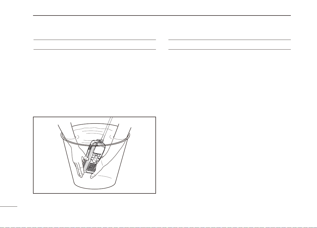
CLEAN THE TRANSCEIVER THOROUGHLY WITH FRESH
WATER after exposure to saltwater. Otherwise, the trans-
ceiver's keys, switches and controllers may become inoperable due to salt crystallization.
NOTE: DO NOT wash the transceiver in water if there is any
reason to suspect the waterproofi ng may not be effective. For
example, in cases where the battery pack rubber seal is damaged, the transceiver/battery pack is cracked or broken, or
has been dropped, or when the battery pack is detached from
the transceiver.
WARNING! NEVER connect the transceiver to an
R
AC outlet. This may pose a fi re hazard or result in an electric
shock.
WARNING! NEVER hold the transceiver so that
R
the antenna is very close to, or touching exposed parts of
the body, especially the face or eyes, while transmitting. The
transceiver will perform best if the microphone is 5 to 10 cm (2
to 4 inches) away from the lips and the transceiver is vertical.
WARNING! NEVER operate the transceiver with
R
other audio accessories at high volume levels. Hearing experts advise against continuous high volume operation. If you
experience a ringing in your ears, reduce the volume level or
discontinue use.
DO NOT modify the transceiver. The transceiver warranty does
not cover any problems caused by unauthorized modifi cation.
BE CAREFUL! The transceiver will become hot when
operating it continuously for long periods of time.
KEEP the transceiver and microphone at least 1 m (3.3 feet)
away from the vessel’s magnetic navigation compass.
KEEP the transceiver out of the reach of children.
iii
Page 5

PRECAUTIONS
CAUTION: MAKE SURE the fl exible antenna, bat-
tery pack and jack cover are securely attached to the transceiver,
and that the antenna and battery pack are dry before
attachment. Exposing the inside of the transceiver to dust or
water will result in serious damage to the transceiver.
DO NOT operate the transceiver near unshielded electri-
cal blast ing caps or in an explosive atmosphere.
DO NOT
push [PTT] when not actually intending to transmit.
DO NOT use or place the transceiver in direct sunlight
or in areas with temperatures below –20°C (–4°F) or above
+60°C
(+140°F), and for the Australian version, below –10°C
or above +55°C
The basic operations, transmission and reception of the
transceiver are guaranteed within the specifi ed operating
temperature range.
operate correctly, or show an indication in the case of long
hours of operation, or after being placed in extremely cold
areas.
(+140°F).
However, the LCD display may not be
DO NOT use harsh solvents such as benzine or alcohol
when cleaning, as they will damage the transceiver surfaces.
BE CAREFUL! The IC-M91D and IC-M92D meet IPX7*
requirements for dust-tight and waterproof protection. However, once the transceiver has been dropped, dust-tight and
waterproof protection cannot be guaranteed because of possible damage to the transceiver’s case or the waterproof
seal.
*
Only when the jack cover or the optional HM-167 is attached.
Even when the transceiver power is OFF, a slight current still
fl ows in the circuits. Remove the battery pack or batteries
from the trans ceiver when not using it for a long time. Otherwise, the installed battery pack or batteries will become exhausted, and will need to be recharged or replaced.
BE CAREFUL! Even if the volume level is set low, the
beeps of the Float ’n Flash, DSC alarm and AquaQuake functions are very loud.
MAKE SURE to turn the transceiver power OFF before
connect ing the supplied/optional equipment.
For U.S.A. only:
CAUTION: Changes or modifi cations to this transceiver, not
expressly approved by Icom Inc., could void your authority to
operate this transceiver under FCC regulations.
iv
Page 6

FCC INFORMATION
FOR CLASS B UNINTENTIONAL RADIATORS
This equipment has been tested and found to comply with
the limits for a Class B digital device, pursuant to part 15 of
the FCC Rules. These limits are designed to provide reasonable protection against harmful interference in a residential
installation. This equipment generates, uses and can radiate
radio frequency energy and, if not installed and used in accordance with the instructions, may cause harmful interference to radio communications. However, there is no guarantee that interference will not occur in a particular installation.
If this equipment does cause harmful interference to radio
or television reception, which can be determined by turning
the equipment off and on, the user is encouraged to try to
correct the interference by one or more of the following measures:
• Reorient or relocate the receiving antenna.
• Increase the separation between the equipment and receiver.
• Connect the equipment into an outlet on a circuit different
from that to which the receiver is connected.
• Consult the dealer or an experienced radio/TV technician
for help.
Icom, Icom Inc. and the Icom logo are registered trademarks of Icom Incorporated (Japan) in Japan, the United States, the United Kingdom, Germany,
France, Spain, Russia and/or other countries.
v
TABLE OF CONTENTS
FOREWORD ......................................................................... i
IMPORTANT .......................................................................... i
EXPLICIT DEFINITIONS ....................................................... i
FEATURES ............................................................................i
IN CASE OF EMERGENCY ................................................. ii
RECOMMENDATION .......................................................... iii
PRECAUTIONS ................................................................... iii
FCC INFORMATION ............................................................v
TABLE OF CONTENTS ........................................................v
1 OPERATING RULES ........................................................1
2 SUPPLIED ACCESSORIES AND ATTACHMENTS .....2–3
Supplied accessories ■ ................................................... 2
Attachments ■ ................................................................. 2
3 PANEL DESCRIPTION .................................................4–9
Front, top, side and rear panels ■ ...................................4
Softkeys ■ .......................................................................6
Function display ■ ..........................................................7
Softkey function ■ ............................................................9
4 PREPARATION ...............................................................10
MMSI code programming ■ ........................................... 10
5 BASIC OPERATION .................................................11–16
Channel selection ■ ......................................................11
Call channel programming ■ .........................................13
Page 7

TABLE OF CONTENTS
Adjusting the volume level ■ ..........................................13
Adjusting the squelch level ■ ......................................... 13
Receiving and transmitting ■ .........................................14
Lock function ■ .............................................................. 15
Monitor function ■ .........................................................15
AquaQuake water draining function ■ ........................... 15
Backlight setting ■ ......................................................... 15
Channel name programming ■ ......................................16
6 SCAN OPERATION ..................................................17–18
Scan types ■ ................................................................17
Setting Favorite (TAG) channels ■ ................................18
Starting a scan ■ ........................................................... 18
7 DUALWATCH/TRI-WATCH .............................................19
Description ■ ................................................................. 19
Operation ■ ...................................................................19
8 DSC OPERATION ..................................................... 20–70
DSC address ID ■ ........................................................ 20
Position and time programming ■ ..................................23
Distress call ■ ................................................................ 24
Transmitting DSC calls ■ ............................................... 28
Receiving DSC calls ■ ..................................................51
Received Call log ■ .......................................................63
Transmitted Call log ■ ....................................................65
DSC Settings ■ .............................................................66
9 OTHER FUNCTIONS ................................................ 71–81
MOB (Man OverBoard) ■ ..............................................71
Waypoint ■ ....................................................................74
Navigation ■
Compass screen ■ ........................................................ 80
GPS status screen ■ ..................................................... 81
10 MENU SCREEN OPERATION ................................ 82–88
Menu screen operation ■ ..............................................82
Menu screen items ■ ..................................................... 83
Radio Settings items ■ .................................................. 84
Confi guration items ■ .................................................... 85
11 BATTERY CHARGING ............................................89–93
Batte ■ ry caution ........................................................... 89
Regular battery charger ■ .............................................91
Optional battery chargers ■ ...........................................92
12 OPTIONAL SPEAKER-MICROPHONE ........................94
HM-167 descriptions ■ .................................................. 94
Attachment ■ .................................................................94
13 TROUBLESHOOTING ................................................... 95
14 SPECIFICATIONS AND OPTIONS .........................96–97
Specifi cations ■ ............................................................. 96
Options ■ ....................................................................... 97
15 VHF MARINE CHANNEL LIST ..................................... 98
16 SAFETY TRAINING INFORMATION .................... 99–100
..................................................................78
vi
Page 8

1
OPERATING RULES
Priorities D
• Read all rules and regulations pertaining to priorities and
keep an up-to-date copy handy. Safety and distress calls
take priority over all others.
• You must monitor Channel 16 when you are not operating
on another channel.
• False or fraudulent distress calls are prohibited under law.
Privacy D
• Information overheard but not intended for you cannot lawfully be used in any way.
• Indecent or profane language is prohibited.
Radio licenses D
(1) SHIP STATION LICENSE
You must have a current radio station license before using
the transceiver. It is unlawful to operate a ship station which
is not licensed.
Inquire through your dealer or the appropriate government
agency for a Ship-Radiotelephone license application. This
government-issued license states the call sign which is your
craft’s identifi cation for radio purposes.
(2) OPERATOR’S LICENSE
A Restricted Radiotelephone Operator Permit is the license
most often held by small vessel radio operators when a radio
is not required for safety purposes.
The Restricted Radiotelephone Operator Permit must be
posted or kept with the operator. Only a licensed radio operator may operate a transceiver.
However, non-licensed individuals may talk over a transceiver if a licensed operator starts, supervises, ends the call and
makes the necessary log entries.
A current copy of the applicable government rules and regulations is only required to be on hand for vessels in which
a radio telephone is compulsory. However, even if you are
not required to have these on hand it is your responsibility to
be thoroughly acquainted with all pertinent rules and regulations.
NOTE: Even though the IC-M92D is capable of operation
on VHF marine channe
83,
according to FCC regulations these simplex channels cannot be lawfully used by the general population in
U.S.A. waters.
ls 3, 21, 23, 61, 64, 81, 82 and
1
Page 9
SUPPLIED ACCESSORIES AND ATTACHMENTS
2
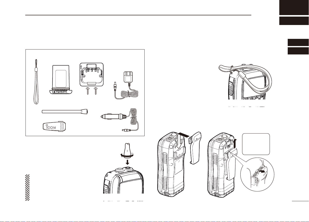
Supplied accessories ■
Battery packHandstrap
Antenna
Belt clip
Battery charger
(with 2 screws)
Attachments ■
D Flexible antenna
Connect the supplied fl exible antenna
to the antenna connector.
CAUTION:
• NEVER carry the transceiver by hold-
ing the antenna.
• Transmitting without an antenna may
damage the transceiver.
AC adapter
(Different type may be
supplied, depending
on the version)
Cigarette lighter cable
D Handstrap
Pass the handstrap through
the loop on the back side of
the transceiver as illustrated
at right. This facilitates carrying.
D Belt clip
Attach/detach the belt clip to the transceiver as illustrated
below.
To attach the belt clip To detach the belt clip
Be careful!
Do not break
w
your finger
nails.
q
1
2
3
4
5
6
7
8
9
10
11
12
13
14
15
16
2
Page 10
SUPPLIED ACCESSORIES AND ATTACHMENTS
2
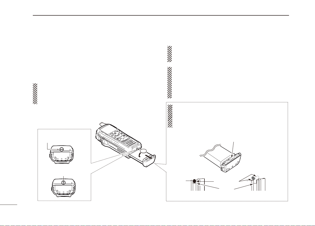
Battery pack D
To remove the battery pack:
Turn the screw counter clockwise one quarter turn, then pull
the battery pack in the direction of the arrow, as shown below.
To attach the battery pack:
Insert the battery pack completely into the transceiver, then
turn the screw clockwise one quarter turn.
NEVER remove or insert the battery pack when the transceiver is wet or soiled. This may result water or dust getting into the transceiver or battery pack and may result in
the transceiver being damaged.
Screw position
when removing battery
NOTE: When removing or attaching the battery pack, use
a coin or standard screwdriver to loosen or tighten the bottom screw.
CAUTION:
When attaching or removing a battery pack, make sure
the rubber seal is set in the groove of the battery pack
correctly. If the seal is not correctly in the groove, it may
be damaged when attaching the battery pack. If the seal is
damaged, waterproof protection is not guaranteed.
NOTE:
When attaching a battery pack, make sure dust or other
material does not adhere to the rubber seal. If dust or other
material is on the seal when attaching a battery pack,
waterproof protection may not be guaranteed.
Make sure the rubber seal is properly seated in the
groove and dust or other material does not adhere to it.
Screw position
when attaching battery
Correct position
Rubber seal
Groove
Battery pack
Incorrect position
Battery pack
3
Page 11
PANEL DESCRIPTION
3
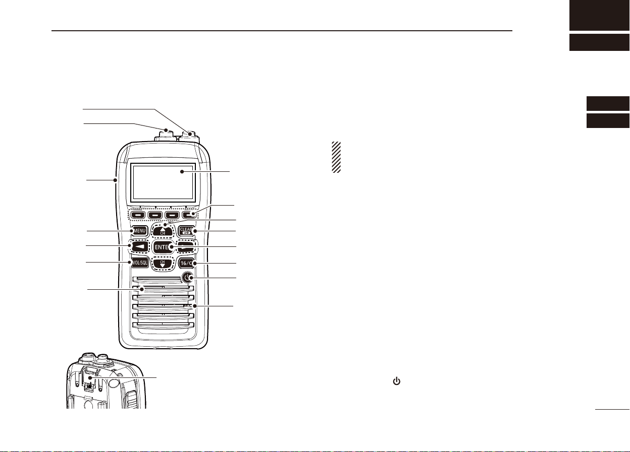
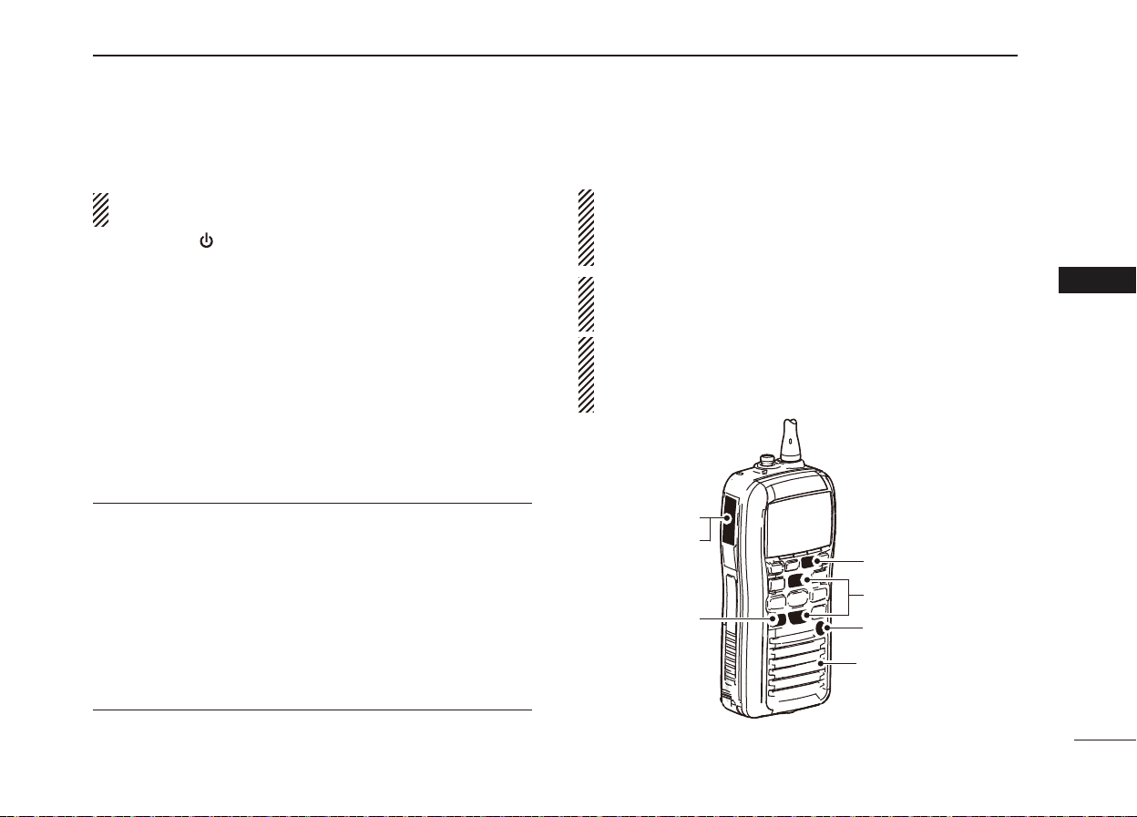
Front, top, side and rear panels ■
q
w
t
y
Speaker
e
r
/+%
Distress key
(p. 24)
Function
display
(pp. 7, 8, 9)
!2
!1
!0
o
i
u
Microphone
q ANTENNA CONNECTOR (p. 2)
Connects to the supplied antenna.
w
SPEAKER-MICROPHONE CONNECTOR [SP MIC]
Connects to the optional external speaker-microphone.
NOTE: Attach the [SP MIC] cap when the optional
speaker-microphone is not used. Otherwise, water will
get into the transceiver.
e PTT SWITCH [PTT]
Hold down to transmit; release to receive. (
r MENU KEY
Push to enter or exit the Menu screen
t LEFT AND RIGHT KEYS [Ω]/[≈]
Push to switch to the previous or next key function that ➥
is assigned to the softkeys. (
Push to select the desired character or number in the ➥
table while in the channel name, position, MMSI code
programming mode, and so on. (
y VOLUME/SQUELCH KEY [VOL/SQL]
Push to enter the volume level adjustment mode. ➥
(
p. 13)
Push again while in the volume level adjustment mode ➥
to enter the squelch level adjustment mode.
Hold down for 1 second to activate the monitor function. ➥
(p. 15)
u POWER KEY [
Hold down for 1 second to turn the power ON or OFF.
]
p. 9)
p. 14)
.
pp. 10, 16, 23)
(p. 94)
1
2
3
4
5
6
7
8
9
10
11
12
13
14
15
16
4
Page 12
PANEL DESCRIPTION
3
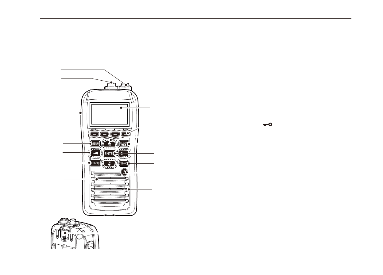
Front, top and rear panels (Continued) ■
q
w
e
r
t
y
Speaker
/+%
Distress key
(p. 24)
Function
display
(pp. 7, 8, 9)
!2
!1
!0
o
i
u
Microphone
i CHANNEL 16 KEY [16/C]
Push to select Channel 16. ( ➥
Hold down for 1 second to select the Call channel. ➥
(
p. 11)
Hold down for 3 seconds to enter the Call channel ➥
programming mode when the Call channel is selected.
(
p. 13)
o ENTER KEY
Push to set the input data, selected item, and so on.
!0 CLEAR/LOCK KEY [
Push to cancel the entered data, or to return to the pre- ➥
vious screen.
Hold down for 1 second to turn the key lock function ON ➥
or OFF. (p.
!1
UP AND DOWN/CHANNEL SELECT KEYS [∫•CH]/[√•CH]
Push to select the operating channels, Menu items, ➥
Menu settings, and so on. (
➥
Push to check Favorite (TAG) channels, change the
scanning direction or manually resume a scan. (
!2 SOFTKEYS
Slide the menu by pushing the [Ω]/[≈] keys, then push ei-
ther of the 4 softkeys to select a menu displayed at the
bottom of the LCD display.
See Softkeys on the next page for more details. (
15)
p. 11)
]
p. 82)
p. 18)
p. 6)
5
Page 13
PANEL DESCRIPTION
3
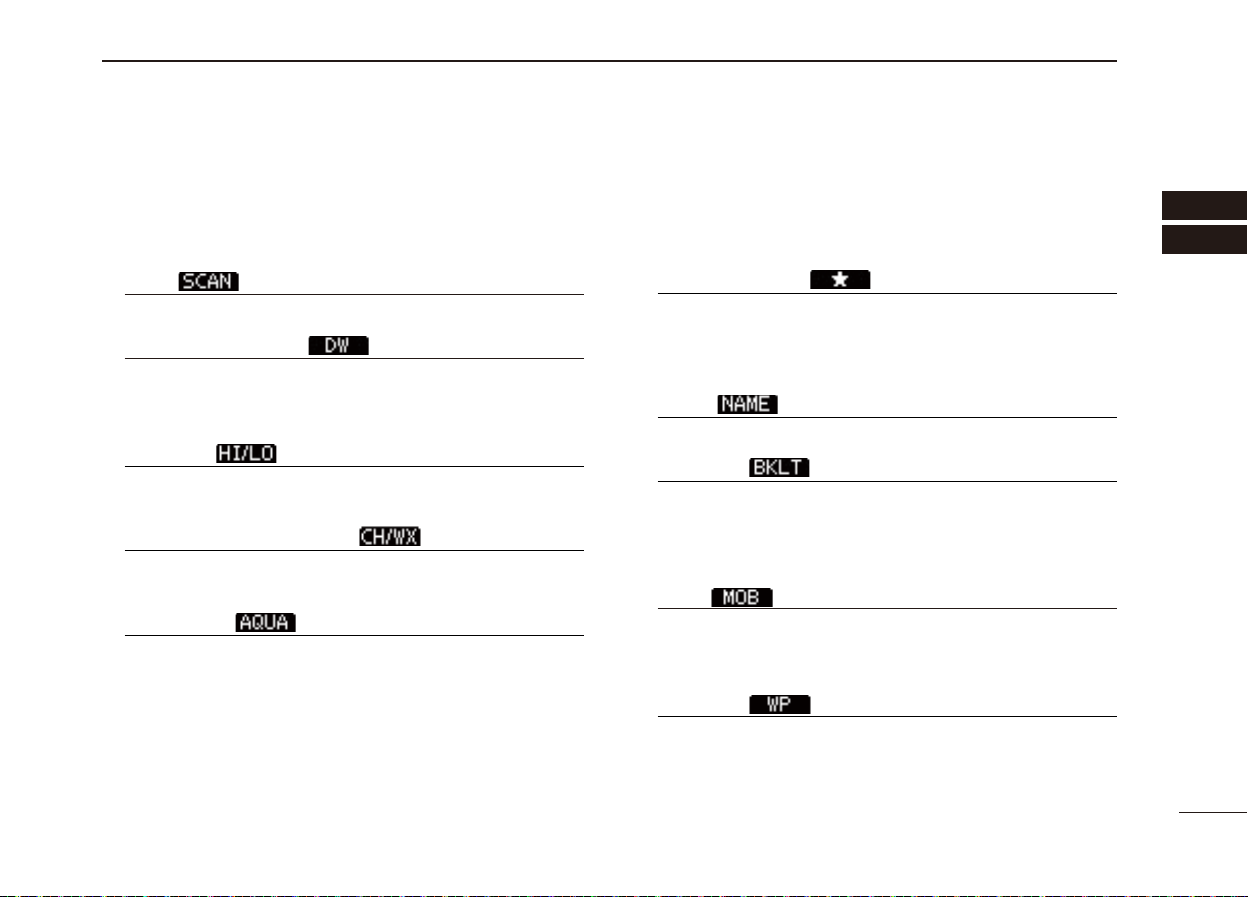
Softkeys ■
The desired functions as described below can be assigned
in the Menu screen.
Scan [
Push to start or stop a Normal or Priority scan.
Dualwatch/Tri-watch [
Push to start a Dualwatch or Tri-watch. ➥
Push to stop a Dualwatch or Tri-watch when either is ➥
activated.
High/Low [
Push to set the power to high or low.
• Some channels are set to only low power.
Channel/Weather Channel [ ] (p. 11)
Push to select either the regular channels or the Weather
channels.
AquaQuake [
While holding down, the AquaQuake function is activated
to clear water away from the speaker grill.
] (p. 17)
] (p. 19)
] (p. 14)
] (p. 15)
Favorite channel [ ] (p. 18)
Push to set or clear the displayed channel as a Favorite ➥
(Tag) channel.
Hold down for 3 seconds to clear or set all Favorite ➥
channels in the selected channel group.
Name [
Push to enter the channel name programming mode.
Backlight [
Push to enter the LCD and key backlight brightness ad-
justment mode.
• While in the adjustment mode, push [∫]/[√][Ω]/[≈] to adjust the
brightness of the LCD and key backlight.
MOB [ ] (p. 71)
Push to enter “MOB” in the menu screen. ➥
Hold down for 1 second to memorize the current position ➥
as the MOB (Man OverBoard) point.
Waypoint [ ] (p. 74)
Push to enter “WAYPOINT” in the menu screen. ➥
➥
Hold down for 1 second to memorize the current position
as a Waypoint.
] (p. 16)
] (p. 15)
1
2
3
4
5
6
7
8
9
10
11
12
13
14
15
16
6
Page 14
PANEL DESCRIPTION
3
Softkeys (Continued) ■
Navigation [ ] (p. 78)
After holding down [MOB], or in the MOB or Waypoint list
screen, push this key to start navigating to the selected
position.
Compass [
Push to display the compass screen to show the vessel’s
course heading, SOG (Speed Over Ground) and COG
(Course Over Ground).
Log [ ] (p. 63)
Push to enter “RCVD CALL LOG” in the DSC CALLS menu.
] (p. 80)
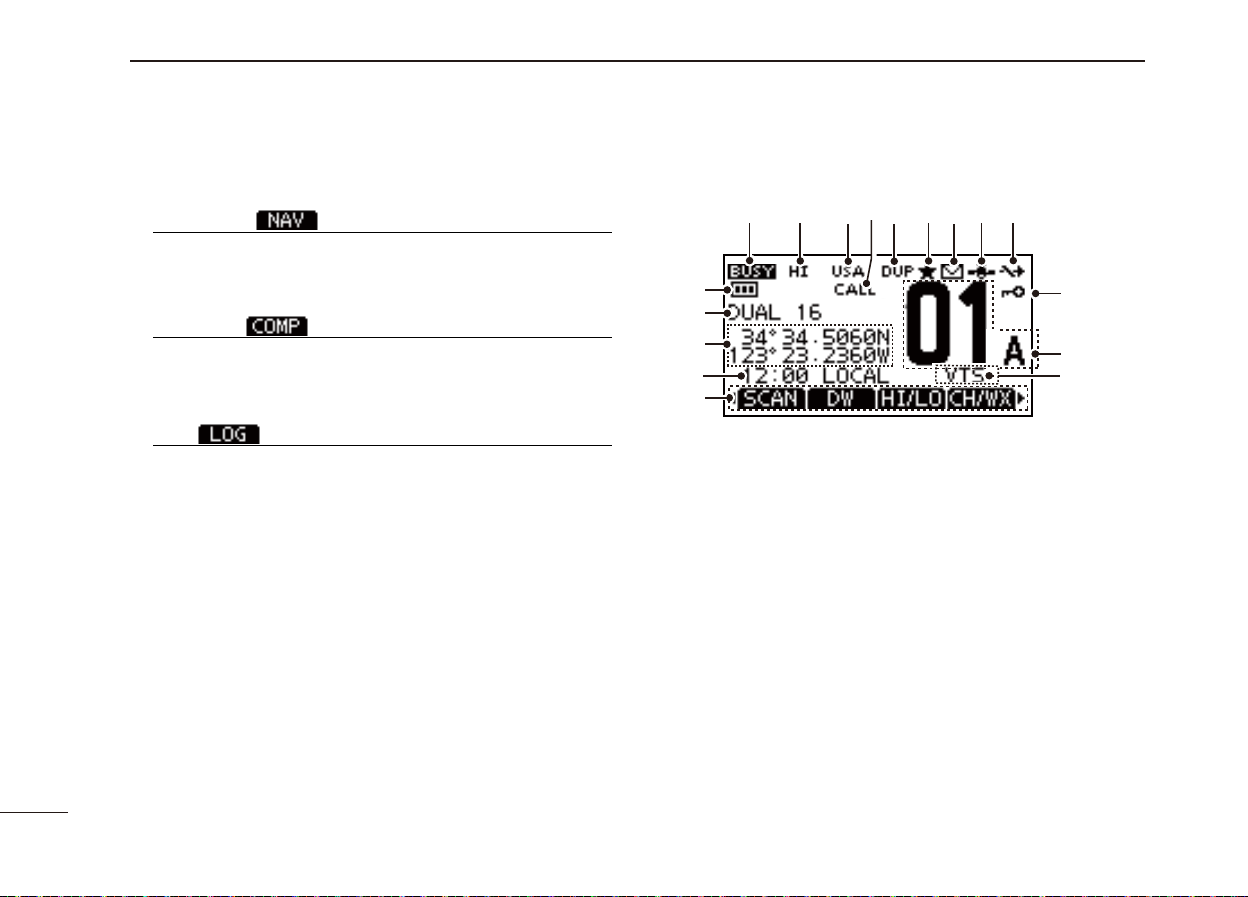
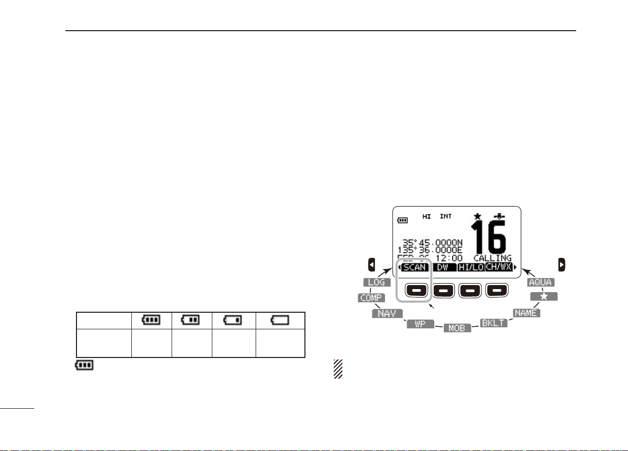
Function display ■
r
q!4w
!7
!6
!5
!3
q BUSY/TRANSMIT INDICATOR (p. 14)
“BUSY” appears when receiving a signal or when the ➥
squelch opens.
“TX” appears while transmitting. ➥
“MONI” appears while the monitor function is activated. ➥
w POWER ICON (p. 14)
“HI” appears when high power is selected. ➥
“LOW” appears when low power is selected. ➥
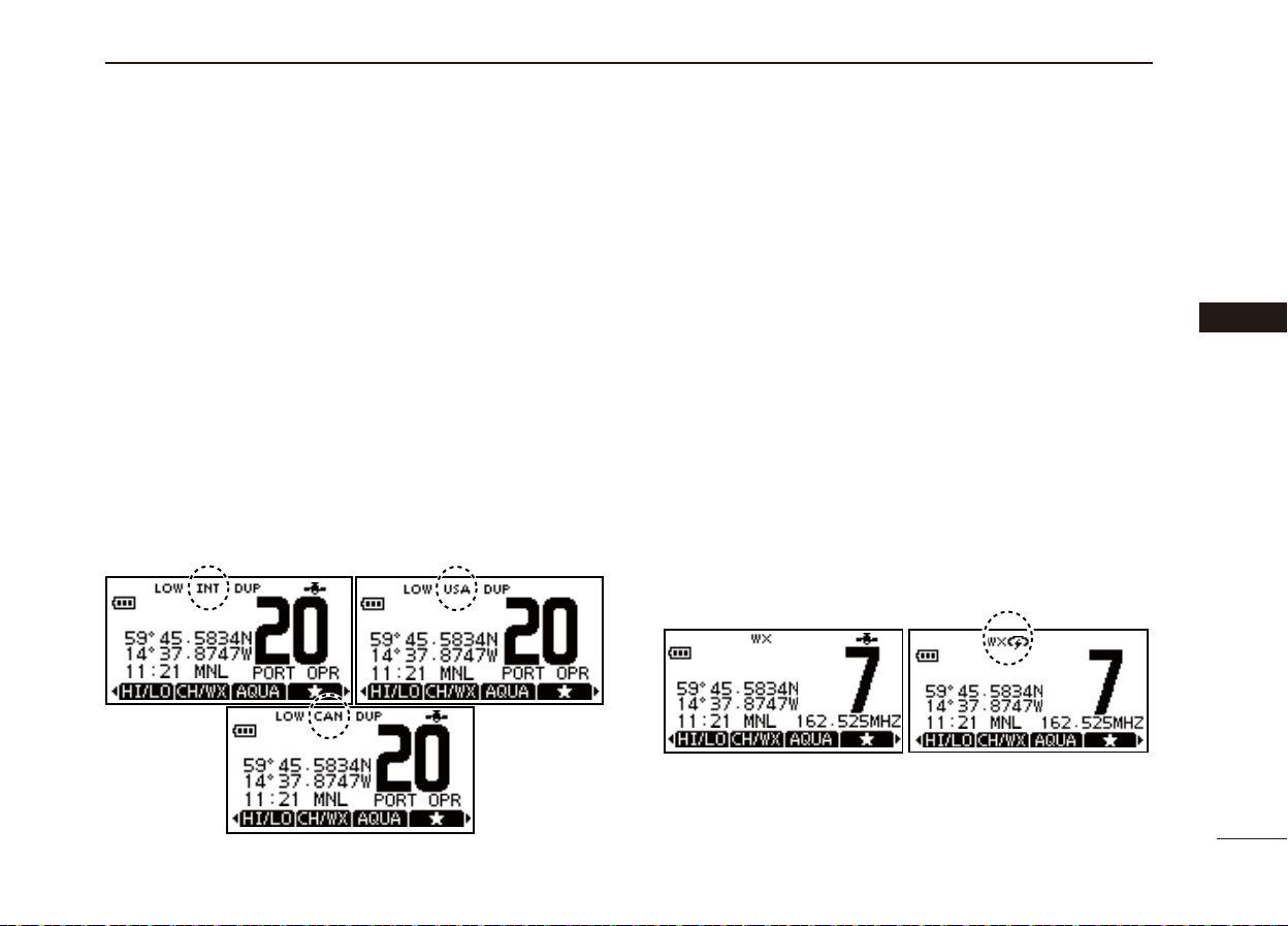
e
CHANNEL GROUP ICON/ WEATHER CHANNEL (p. 12)
The selected channel group icon is displayed as U.S.A. ➥
“USA,” International “INT,” Canadian “CAN”
channel “WX
r CALL CHANNEL ICON (p. 11)
Appears when Call channel is selected.
e
,
”
depending on the transceiver version.
t
y
ui
o
!0
!1
!2
or weather
7
Page 15

PANEL DESCRIPTION
3
1
t DUPLEX ICON (p. 12)
Appears when a duplex channel is selected.
y FAVORITE CHANNEL ICON (p. 18)
Appears while a Favorite (TAG) channel is selected.
u MAIL ICON (p. 51)
Blinks when there is an unread message.
i GPS ICON
Stays ON while the GPS data is received, and a valid ➥
position is received.
Blinks when an invalid position is being received. ➥
o SWITCH ICON (p. 67)
Appears when the “CH 16 SWITCH” in DSC Settings is set
to ‘OFF.’
!0 LOCK ICON (p. 15)
Appears while the lock function is activated.
!1 CHANNEL NUMBER READOUT
Shows the selected operating channel number.
• When a simplex channel is selected, “A” appears.
!2 CHANNEL NAME FIELD (p. 16)
The channel name appears, if programmed. ➥
“DSC CHECK” blinks while receiving on CH70. ➥
!3 KEY ICON (p. 9)
Shows the programmed function of the softkeys on the
front panel.
!4 TIME ZONE INDICATOR
Shows the current time when GPS data is received, or ➥
the time is manually programmed.
• “??” will blink when invalid GPS data is received for 30
seconds.
• “?? ” will blink when manually input GPS data is no longer
valid after 4 hours, and then “NO TIME” will appear after
23.5 hours.
“LOCAL” appears when the offset time is set. ➥
➥
“NO TIME” appears when no GPS data is received and
no time data is manually input.
➥
“MNL” appears when the time is manually programmed.
2
3
4
5
6
7
8
9
10
11
12
13
14
15
16
8
Page 16
PANEL DESCRIPTION
3
Function Display (Continued) ■
!5 POSITION INDICATOR
Shows the current position when valid GPS data is re- ➥
ceived or the position is manually programmed.
• “??” will blink when invalid GPS data is received for 30
seconds.
• “?? ” will blink when manually input GPS data is no longer
valid after 4 hours, and then “NO POSITION” will appear
after 23.5 hours.
• “NO POSITION” is displayed when no GPS data is received
since the transceiver power turned ON.
• “NO POSITION” appears when no GPS data is received,
and no position is manually input.
!6 SCAN INDICATOR
“SCAN 16” is displayed during a Priority scan; “SCAN” ➥
appears during a Normal scan. (p.
“DUAL 16” appears during Dualwatch; “TRI 16” appears ➥
during Tri-watch. (
!7 BATTERY INDICATOR
Shows the battery’s remaining power.
Indication
Battery level
blinks when the battery is over charged.
p. 19)
Full Middle
17)
Charging
required
No battery
Softkey function ■
Various functions can be assigned to the softkeys.
When the key function is assigned, the key icon is displayed
above the softkeys, as shown below.
Softkey function selection D
When “Ω” or “≈” is displayed beside the key icon, pushing [Ω]
or [≈] sequentially displays the previous or next key function
that is assigned to the softkey.
Push Push
*
*Push this key to start or stop a scan.
The order of the key icons may differ, depending on the
preprogramming.
9
Page 17
PREPARATION
4
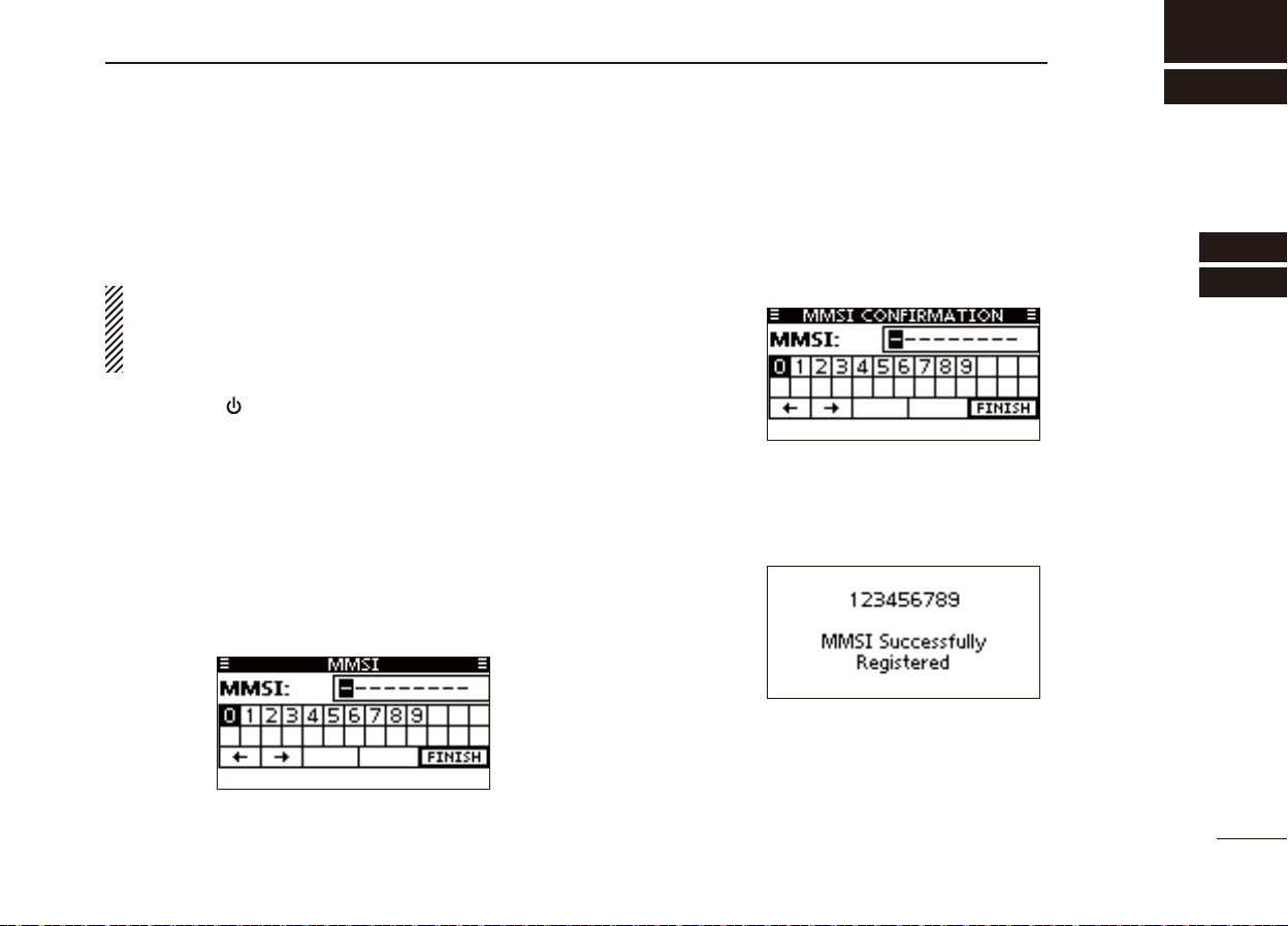
MMSI code programming ■
The 9 digit MMSI (Maritime Mobile Service Identity: DSC self
ID) code can be programmed at power ON.
This initial code setting can be performed only once.
After being set, it can be changed by only your dealer
or distributor. If your MMSI code has already been programmed, this programming is not necessary.
Hold down [ q
• Three short beeps sound, and “NO DSC MMSI” is displayed.
Push [ENTER] to start the MMSI code programming. w
• Push [CLEAR] twice to cancel the programming, and go to the
normal operating screen. In this case, the transceiver cannot
make a DSC call. To program the MMSI code, turn OFF the
power, then turn it ON again.
Enter your MMSI code in the following manner: e
• Select a desired number using [∫]/[√]/[Ω]/[≈].
• Push [ENTER] to set it.
• To move the cursor, select either arrow, “←” or “→,” then push
[ENTER].
] to turn ON the power.
Repeat step re to enter all 9 digits.
After entering the 9 digit code, “FINISH” is automatically t
selected, and then push [ENTER] to set it.
The “MMSI CONFIRMATION” screen is displayed. y
Enter your MMSI code again for confirmation. u
• Enter in the same manner as steps e through t.
When your MMSI code programming is successfully com- i
pleted, the screen as shown below is briefl y displayed.
• After that, the normal operating screen is displayed.
The programmed MMSI code can be checked in the MENU
screen. (
p. 83)
1
2
3
4
5
6
7
8
9
10
11
12
13
14
15
16
10
Page 18
5
BASIC OPERATION
Channel selection ■
IMPORTANT: Prior to using the transceiver for the fi rst
time, the battery pack must be fully charged for optimum
life and operation. To avoid damage to the transceiver,
turn the power OFF while charging.
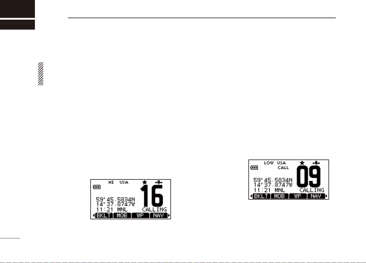
Channel 16 D
Channel 16 is the distress and safety channel. It is used for
establishing initial contact with a station and for emergency
communications. Channel 16 is monitored during both Dual-watch and Tri-watch. While in the standby condition, you
must monitor Channel 16.
Push [16/C] to select Channel 16. q
Push [ w
CH/WX] to return to the selected channel before
Channel 16, or push [∫](CH) or [√](CH) to select an operating channel.
Call channel D
Each regular channel group has separate leisure-use call
channels. The call channel is monitored during Tri-watch.
The call channels can be programmed and are used to store
your most often used channel in each channel group for quick
recall. (p
• “CALL” and the call channel number are displayed.
• Call channel can be re-programmed. See the “Call channel pro-
. 13)
Hold down [16/C] q for 1 second to select Call channel.
gramming” on page 13 for details.
Select w [CH/WX] to return to the selected channel before
the call channel, or push [∫](CH) or [√](CH) to select the
operating channel.
Hold down [16/C] key
for 1 second
11
Push [16/C] key
Page 19
BASIC OPERATION
5
Channel group selection D
There are preprogrammed U.S.A. channels, International
channels and Canadian* channels. These channel groups
may be specifi ed for the operating area.
* For only the U.S.A. and EXP transceiver versions.
Push q [MENU].
Push [ w Y]/[Z] to select “Radio Settings”.
Push [ e Y]/[Z]
TER].
r Push [Y]/[Z] to select the desired channel group, and then
push [ENTER].
• U.S.A. (USA), International (INT) and Canadian (CAN) channel
groups can be selected.
t Push [EXIT] to exit the Menu screen.
Push y
• “DUP” appears for duplex channels.
• “A” appears for simplex channel.
to select “CHAN Group”, and then push [EN-
[Y](CH)/[Z](CH) to select a channel.
Weather channels D
The transceiver has 10 pre-programmed weather channels.
These are used for monitoring broadcasts from NOAA (National Oceanographic and Atmospheric Administration.) The
transceiver can automatically detect a weather alert tone on
the selected weather channel or while scanning. (p
To Select a Weather channel:
Push
[CH/WX] to select a weather channel.
• “WX” is displayed when a weather channel is selected.
• The Weather channel alert icon appears when the alert function
is turned ON.
To set the Weather Alert:
Push [MENU]. q
Push [ w Y]/[Z] to select “Radio Settings” and then push
[ENTER].
Select e “WX Alert” and then push [ENTER].
r Select “ON” or “ON with Scan” to set the Weather Alert.
t Push
• WX Alert icon appears.
[EXIT] to exit the Menu screen.
. 17)
1
2
3
4
5
6
7
8
9
10
11
12
13
14
15
16
12
Page 20
BASIC OPERATION
5
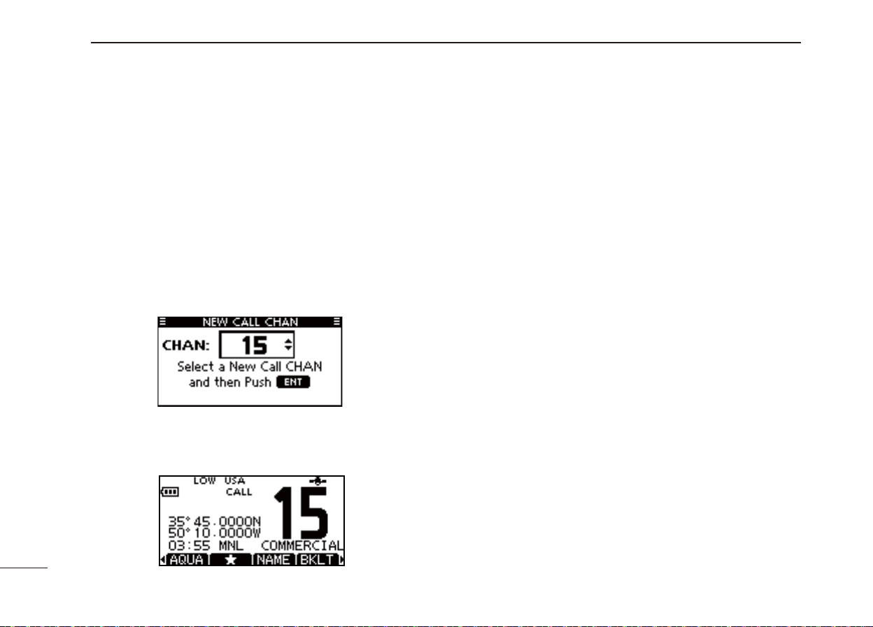
Call channel programming ■
You can program the call channel with your most often-used
channels in each channel group for quick recall.
Select the q
nel group
Hold down [16/C] for 1 second to select the call channel of w
the selected channel group.
• “CALL” and call channel number are displayed.
Hold down [16/C] again for 3 seconds until long beep stops e
with two short beeps.
• The channel programming mode screen is displayed.
r Push [Y](CH)/[Z](CH) to select the desired channel.
t Push [ENTER] to program the selected channel as the call
channel.
•
The display automatically returns to the normal operating mode.
desired U.S.A., Canada or International chan-
to be programmed. (p. 12)
Adjusting the volume level ■
The volume level can be adjusted with [VOL/SQL] and [∫]/
[
√
]/[Ω]/[≈] keys.
q
Push [VOL/SQL] once to enter the volume adjustment
mode, then adjust the volume level with
•The transceiver has 20 volume levels and OFF.
•
If no key operation is performed for 5 seconds, the transceiver
sets the selected level, and returns to the normal mode.
w
Push [ENTER] to set, and exit the volume adjustment mode.
• Push [CLEAR] to cancel.
[∫]/[√] or [Ω]/[≈].
Adjusting the squelch level ■
The squelch level can be adjusted with [VOL/SQL] and [∫]/
[
√
]/[Ω]/[≈] keys.
In order to receive signals properly, as well as for the scan
to function effectively, the squelch must be adjusted to its
proper level.
Push [VOL/SQL] twice to enter the squelch adjustment q
mode, then adjust the squelch level with [∫]/[√] or [Ω]/[≈].
• The transceiver has 11 squelch levels: OPEN is completely
open, 10 is tight squelch and 1 is loose squelch.
•
If no key operation is performed for 5 seconds, the transceiver
sets the selected level, and returns to the normal mode.
w
Push [ENTER] to set, and exit the squelch adjustment mode.
• Push [CLEAR] to cancel.
13
Page 21
BASIC OPERATION
5
Receiving and transmitting ■
CAUTION: Transmitting without an antenna will damage
the transceiver.
Hold down [ q
Set the volume and squelch levels with [VOL/SQL]. w
Push e
[Y](CH)/[Z](CH) to select the desired channel.
•
Further adjustment of the audio may be necessary at this point.
r Select [HI/LO] to select the output power if necessary.
• “HI” appears when high power is selected; “LOW” when low
power is selected.
• Choose low power for short range communications, choose
high power for longer distance communications.
• Some channels are for low power only.
t
Hold down [PTT] to transmit, then speak into the microphone.
• “TX” appears.
• Channel 70 cannot be used for transmission.
y Release [PTT] to receive.
Information ✓
The Noise Cancel function reduces random noise com- ➥
ponents in the transmit and/or receive signal. See pag
86
for details
The transceiver monitors channel 70 every specifi c ➥
time period even when standing by on an operating
channel.
•
“DSC CHECK” is displayed when channel 70 is busy.
• The channel 70 monitoring confi guration can be changed in
DSC Settings. See page 69 for details.
] for 1 second to turn power ON.
e
IMPORTANT:
ted signal, pause a few seconds after pushing [PTT], hold
the microphone 5 to 10 cm (2 to 4 inches) from your mouth
and speak into the microphone at a normal voice level.
NOTE: The transceiver has a power save function to con-
serve battery power. The power save function is activated
automatically when no signal is received for 5 seconds.
To prevent accidental prolonged transmission, the trans-
ceiver has a time-out timer function. This timer cuts a
transmission OFF after 5 minutes of continuous transmission.
To maximize the readability of your transmit-
t
y
r
e
w
q
Microphone
1
2
3
4
5
6
7
8
9
10
11
12
13
14
15
16
14
Page 22

BASIC OPERATION
5
15
Lock function ■
This function electronically locks all keys (except for [PTT],
[DISTRESS] and [
and function access.
Push [CLEAR/ ➥
ON and OFF.
• The lock function is automatically released when DSC call is
received, or [DISTRESS] is pushed.
]) to prevent accidental channel changes
] for 1 second to turn the lock function
Displayed when
the lock function
is activated.
Monitor function ■
The Monitor function opens the squelch by holding down
[VOL/SQL] for 1 second.
• “ ” appears while the function is activated.
The function can be set to “PUSH” or “HOLD” in the following
manner.
Select “Configuration” in the “MENU” screen. q
Select “Monitor” to enter the “Push” or “Hold” selecting mode. w
• Push:
• Hold: The monitor function is activated by holding down [VOL/
The monitor function is activated by holding down [VOL/SQL]
for 1 second. The squelch opens while holding down the key.
SQL] for 1 second. The squelch stays open until any key
is pushed.
AquaQuake water draining ■
function
The AquaQuake water draining function clears water away
from the speaker grill. Without this function, water may muffl e
the sound coming from the speaker. The transceiver emits a
vibrating beep when this function is activated.
While holding down [AQUA], the AquaQuake function is acti- ➥
vated to clear water away from the speaker grill.
• Beep sounds, regardless of the volume level setting.
• Activates for 10 seconds in maximum to drain water.
• The transceiver never accepts key operation while the AquaQuake function is activated.
• The AquaQuake function can not be activated when an optional
speaker-microphone is connected.
Backlight setting ■
This function lights the function display and keys, and it is
convenient for night-time operation.
Select q [BKLT] to enter the backlight adjusting mode.
Push w [∫]/[√] or [Ω]/[≈] to adjust the brightness level be-
tween 1(minimum) to 7 (maximum) or OFF.
• The default setting is 4.
• The display returns automatically to the main menu after 5 seconds without no key operation is been performed.
• The backlight automatically turns OFF when no key operation
is performed for 5 seconds.
Page 23
BASIC OPERATION
5
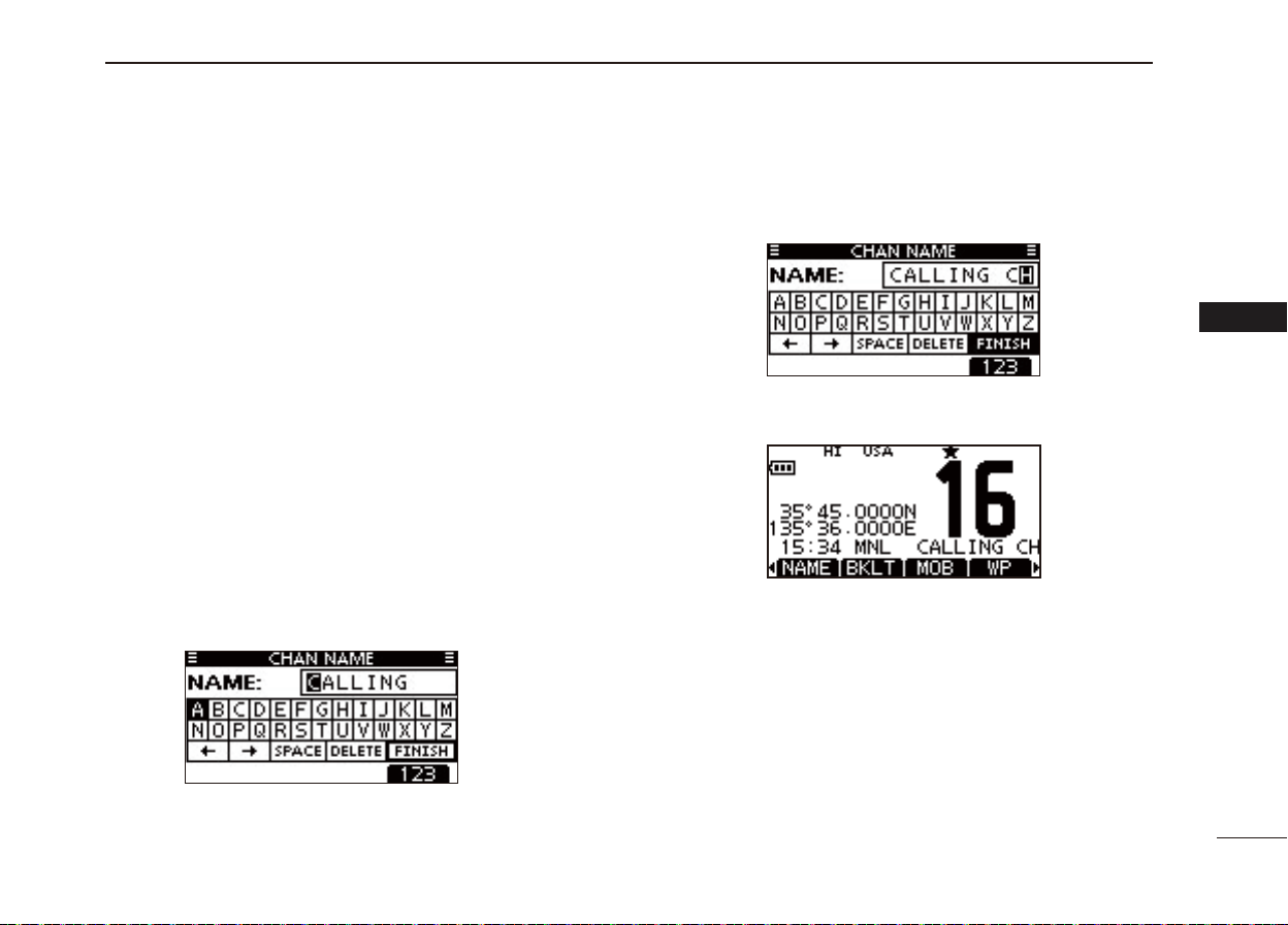
Channel name programming ■
Each channel can be assigned a unique alphanumeric ID of
up to 10 characters.
Capital letters, 0 to 9, some symbols (! " # $ % & ' ( ) * + , – .
/ [ \ ] ^ _ : ; < = > ?) and space can be used.
Push [ q ∫](CH) or [√](CH) to select a channel.
• First, cancel the Dualwatch, Tri-watch or Scan function, if activated.
Push [NAME] to open the channel name programming w
screen.
• A black box is displayed on the fi rst character.
Enter the desired channel name in the following manner: e
• Select a desired character using [∫]/[√]/[Ω]/[≈].
• Push [ENTER].
• To move the cursor, select either arrow, “←” or “→,” then push
[ENTER].
• Select “SPACE,” then push [ENTER] to input a space.
• Select “DELETE,” then push [ENTER] to delete a character.
• Push [CLEAR] to cancel and return to the previous screen.
Repeat step re to input all characters.
Push [ t Ω]/[≈]/[∫]/[√] to select “FINISH,” then push [EN-
TER] to set and return to the previous screen.
1
2
3
4
5
6
7
8
9
10
11
12
13
14
15
16
16
Page 24
6
SCAN OPERATION
Scan types ■
Scanning is an effi cient way to locate signals quickly over a
wide frequency range. The transceiver has both priority scan
and normal scan.
When the Weather Alert function is turned ON, the weather
channel is also checked while scanning. (p. 85)
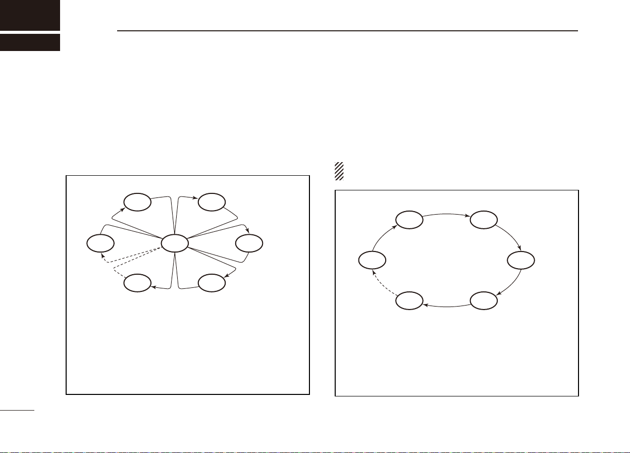
PRIORITY SCAN
CH 01
WX*
CH 05 CH 04
*
When the weather alert function is activated.
Priority scan sequentially searches through all
Favorite channels while monitoring Channel 16.
When a signal is detected on Channel 16, scan
pauses until the signal disappears; when a signal is
detected on a channel other than Channel 16, scan
becomes Dualwatch until the signal disappears.
CH 16
CH 02
CH 03
Set the Favorite channels (scanned channels) before scanning. Clear the Favorite for unwanted channels which inconveniently stop scanning, such as those for digital communications.
Choose the desired scan type from “Priority” or “Normal” in
the set mode. (p. 84)
NORMAL SCAN
CH 01 CH 02
WX*
CH 05 CH 04
*
When the weather alert function is activated.
Normal scan, like Priority scan, searches through all
Favorite channels in sequence. However, unlike Priority
scan, Channel 16 is not checked unless Channel 16 is
set as a Favorite channel.
CH 03
17
Page 25
SCAN OPERATION
6
Setting Favorite channels ■
For more effi cient scanning, add the desired channels as Favorite channels, or clear
Channels that are not tagged will be skipped while scanning.
Favorite channels can be independently assigned to each
channel group (U.S.A., International and Canada*).
* For only the U.S.A. and EXP transceiver versions.
q
Select the desired channel group. (p. 12)
w
Select the desired channel to be set as a Favorite channel.
Push [ e ] to set the displayed channel as a Favorite channel
• “ ”appears on the display.
To cancel the Favorite channel setting, repeat step re.
• “ ”disappears.
Clearing (or setting) all tagged channels ✓
Hold down [] for 3 seconds (until a long beep changes to
2 short beeps) to clear all Favorite channel settings in the
selected channel group.
• Repeat above procedure to set all channels as Favorite channels.
[Example]: Starting a Normal scan.
“ ” for unwanted channels.
Push
[SCAN]
Starting a scan ■
First, set the scan type (Priority or Normal scan), WX Alert func-
tion
and scan resume timer in the Menu screen. (pp. 84, 85)
Select the desired channel group. (p. q
Set the Favorite channels, as described to the left. w
Make sure the squelch is closed to start a scan. e
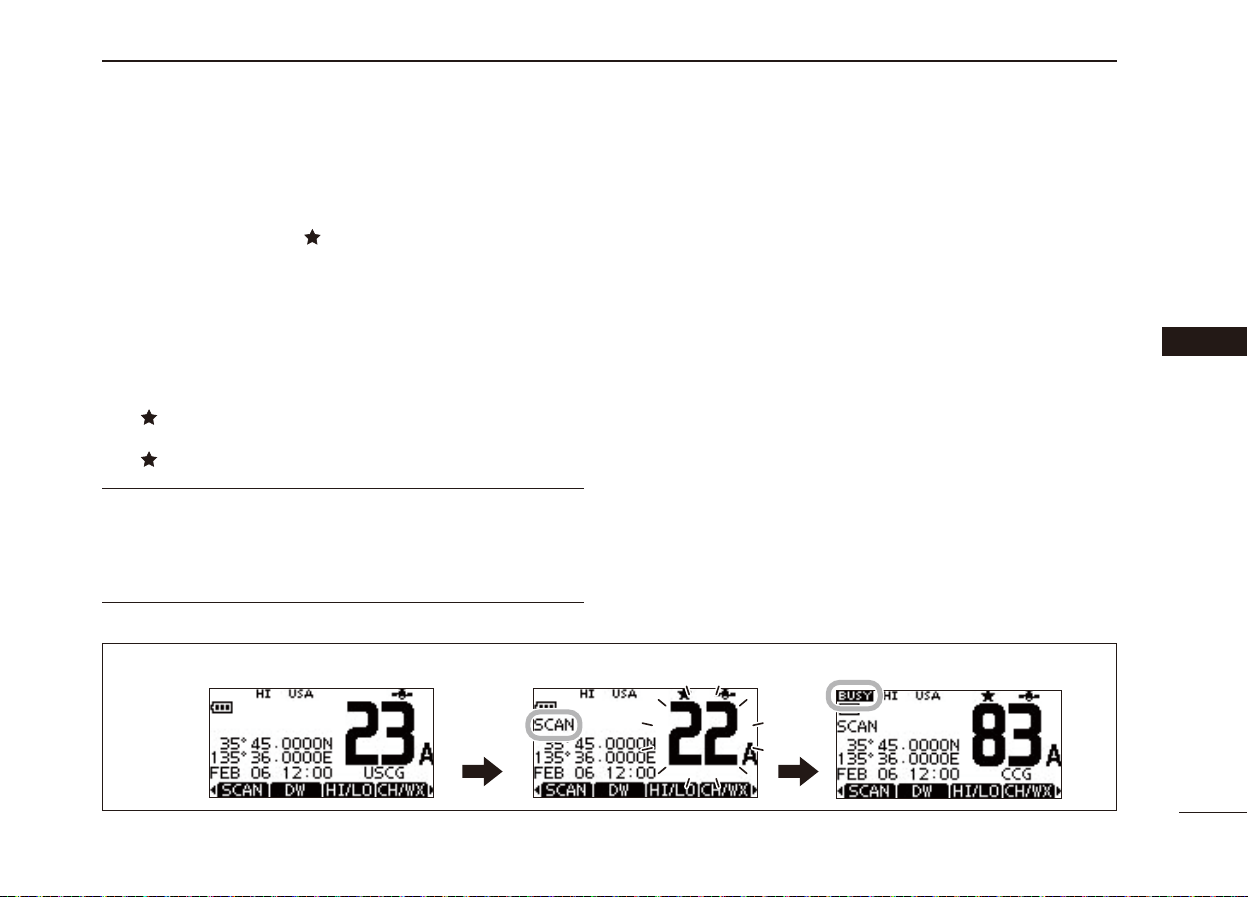
Push [SCAN] to start a Priority or Normal scan. r
• “SCAN 16” appears during a Priority scan; “SCAN” appears
.
Scan starts. When a signal is received.
during a Normal scan.
• When a signal is detected, the scan pauses until the signal
disappears, or resumes after pausing 5 seconds, depending
on the setting. (Channel 16 is still monitored during a Priority
scan.)
• Push [Y]/[Z] check the scanning Favorite channels, change
the scanning direction or manually resume the scan.
• A beep tone sounds and “16” blinks when a signal is received
on Channel 16 during a Priority scan.
To stop the scan, push [CLEAR] or repeat step tr.
12
)
1
2
3
4
5
6
7
8
9
10
11
12
13
14
15
16
18
Page 26
7
DUALWATCH/TRI-WATCH
Description ■
Dualwatch monitors Channel 16 while you are receiving on
another channel; Tri-watch monitors Channel 16 and the
call channel while receiving another channel. Dualwatch/Triwatch is convenient for monitoring Channel 16 when you are
operating on another channel.
DUALWATCH/TRI-WATCH SIMULATION
Call
channel
Ch 16
Ch 88
Ch 88
Ch 16
Ch 88
Dualwatch Tri-watch
• If a signal is received on Channel 16, Dualwatch/Tri-watch
pauses on Channel 16 until the signal disappears.
• If a signal is received on the call channel during Tri-watch,
Tri-watch becomes Dualwatch until the signal disappears.
• To transmit on the selected channel during Dualwatch/
Tri-watch, hold down [PTT].
Ch 9
Operation ■
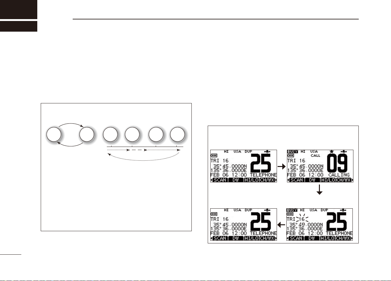
Select Dualwatch or Tri-watch in the Menu screen. (p. 84) q
Push [ w Y](CH) or [Z](CH) to select the desired operating
channel.
Push [DW] to start a Dualwatch or Tri-watch scan. e
• “DUAL 16” appears during Dualwatch; “TRI 16” appears during
Tri-wa tc h.
• A beep tone sounds when a signal is received on Channel 16.
To cancel Dualwatch or Tri-watch, push [DW] again. r
[Example]: Operating Tri-watch on INT Channel 25.
Tri-watch starts.
Tri-watch resumes after
the signal disappears.
Signal is received
on Call channel.
Signal received on Channel 16 takes priority.
19
Page 27
DSC OPERATION
8
DSC address ID ■
Programming Individual ID D
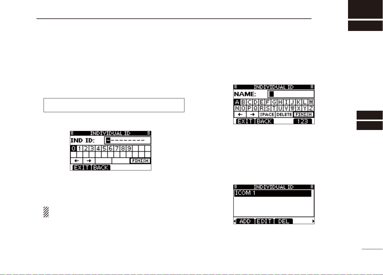
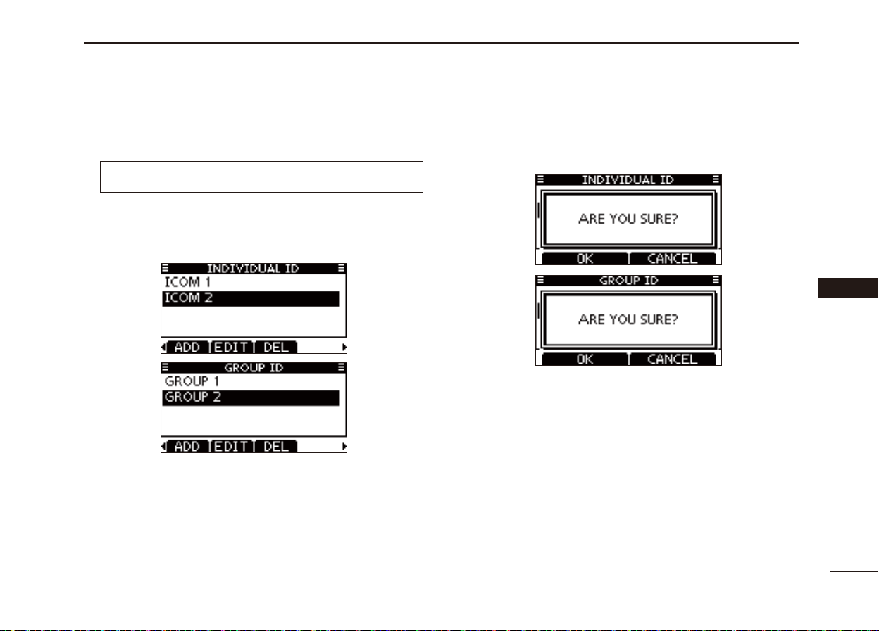
A total of 100 DSC address IDs can be programmed and assigned a name of up to 10 characters.
Enter “INDIVIDUAL ID” in the DSC SETTINGS menu. q
❮MENU❯ ➪ ❮DSC Settings ❯ ➪ ❮
(Push [MENU])
Push [ADD]. w
• The “INDIVIDUAL ID” program screen is displayed.
Enter a desired individual ID in the following way: e
• Select a desired number using [Ω]/[≈].
• Push [ENTER] to set it.
• To move the cursor, select either arrow, “←” or “→,” then push
[ENTER].
The fi rst digit is specifi ed as ‘0’ for a Group ID.
The fi rst two digits are ‘0’ for any Coast station ID.
Repeat step re to enter all 9 digits.
(Push
[Y]/[Z]
, then push [ENTER].)
Individual ID
❯
After entering the 9 digit code, push [ENTER] to set it. t
• The ID name programming screen is displayed.
Enter a desired 10 digit ID name in the following way: y
• Select a desired character using [∫]/[√]/[Ω]/[≈].
• Push [ENTER] to set it.
• To move the cursor, select either arrow, “←” or “→,” then push
[ENTER].
• Push [123] then [!$?] then [ABC] to select a character group.
After entering the ID name, push [ u ∫]/[√]/[Ω]/[≈] to select
“FINISH,” then push [ENTER] to program it.
• The “INDIVIDUAL ID” list screen is displayed.
Push [MENU] to exit the MENU screen. i
1
2
3
4
5
6
7
8
9
10
11
12
13
14
15
16
20
Page 28
New2001
New
DSC OPERATION
8
Programming Group ID D
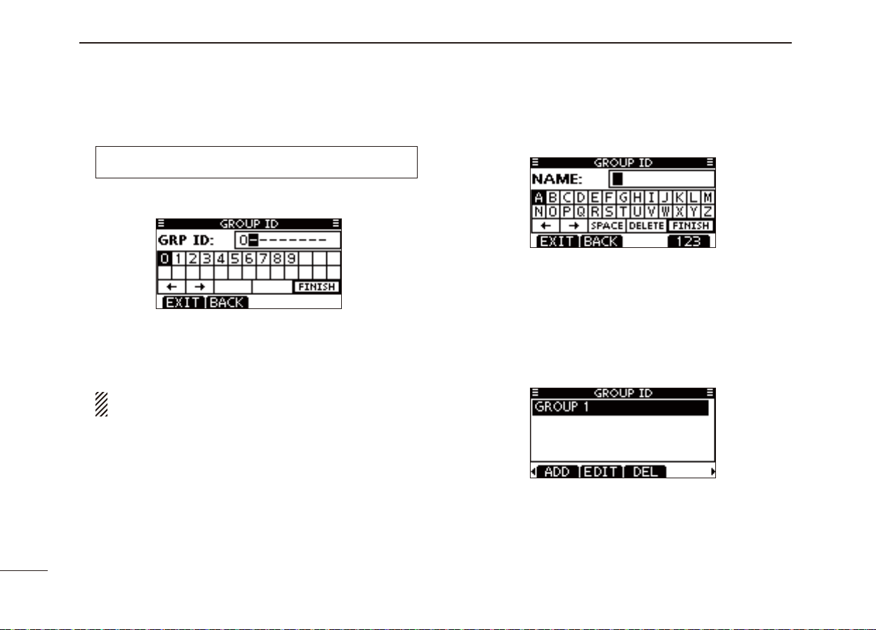
Enter “GROUP ID” in the DSC SETTINGS menu. q
❮MENU❯ ➪ ❮DSC Settings❯ ➪ ❮
(Push [MENU])
(Push
[Y]/[Z]
, then push [ENTER].)
Push [ADD]. w
• The “GROUP ID” program screen is displayed.
Enter a desired group ID in the following way: e
• Select a desired number using [Ω]/[≈].
• Push [ENTER] to set it.
• To move the cursor, select either arrow, “←” or “→,” then push
[ENTER].
The fi rst digit is fi xed as ‘0’ for a Group ID.
The fi rst two digits are ‘0’ for any Coast station ID.
Group ID
❯
After entering the 9 digit code, push [ENTER] to set it. t
• The Group ID name programming screen is displayed.
Enter a desired 10 digit ID name in the following way: y
• Select a desired character using [∫]/[√]/[Ω]/[≈].
• Push [ENTER] to set it.
• To move the cursor, select either arrow, “←” or “→,” then push
[ENTER].
• Push [123], [!$?] or [ABC] to select a character group.
After entering the ID name, push [ u ∫]/[√]/[Ω]/[≈] to select
“FINISH,” then push [ENTER] to program it.
• The “GROUP ID” list screen is displayed.
21
Repeat step re to input the specifi c 9 digits group code.
Push [MENU] to exit the MENU screen. i
Page 29
New2001
Deleting Individual/Group ID D
Enter “INDIVIDUAL ID” or “GROUP ID” in the DSC SET- q
TINGS menu.
❮MENU❯ ➪ ❮DSC Settings❯ ➪ ❮
(Push [MENU])
• When no address ID is programmed, “No ID” is displayed. In this
case, push [MENU] to exit the MENU screen.
Push [ w Y]/[Z] to select a desired ID name, then push
[DEL].
(Push
[Y]/[Z]
Individual ID
, then push [ENTER].)
❯/❮
Group ID
❯
Push [OK] to delete the ID, and return to the “INDIVIDUAL e
ID” or “GROUP ID” list screen.
• Push [CANCEL] to cancel it.
Push [MENU] to exit the MENU screen. r
DSC OPERATION
8
1
2
3
4
5
6
7
8
9
10
11
12
13
14
15
16
22
Page 30
New2001
New
DSC OPERATION
8
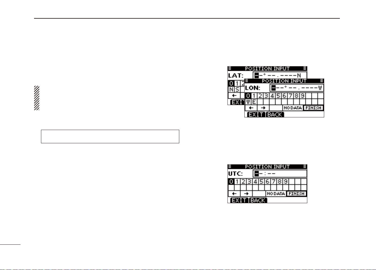
Position and time programming ■
A Distress call should include the ship’s position and time. If
no GPS data is received, your position and UTC (Universal
Time Coordinated) time should be manually input.
• Manual programming is disabled while GPS data is received.
• Manually programmed position and time will be held for
only 23.5 hours.
23
Enter “POSITION INPUT” in the DSC SETTINGS menu. q
❮MENU❯ ➪ ❮DSC Settings❯ ➪ ❮Position Input❯
(Push [MENU])
(Push
[Y]/[Z]
, then push [ENTER].)
Edit your latitude and longitude position using [ w ∫]/[√]/[Ω]/
[≈].
• Select a desired number using [Ω]/[≈].
• Push [ENTER] to set it.
• To move the cursor, select either arrow, “←” or “→,” then push
[ENTER].
• Select N (North latitude) or S (South latitude) when the cursor is
on the ‘N’ or ‘S’ position.
• Select W (West longitude) or E (East longitude) when the cursor
is on the ‘W’ or ‘E’ position.
After entering the position, push [ENTER] to program it. e
The UTC time programming screen is displayed, enter the r
UTC time in the following way:
• Select a desired number using [Ω]/[≈].
• Push [ENTER] to set it.
• To move the cursor, select either arrow, “←” or “→,” then push
[ENTER].
Push [ENTER] to program your position and time. t
• Return to the “DSC SETTINGS” screen.
Page 31

New2001
Distress call ■
A Distress call should be transmitted if, in the opinion of the
Master, the ship or a person is in distress and requires immediate assistance.
NEVER MAKE A DISTRESS CALL IF YOUR SHIP OR A
PERSON IS NOT IN AN EMERGENCY. A DISTRESS
CALL SHOULD BE MADE ONLY WHEN IMMEDIATE
HELP IS NEEDED.
Simple call D
Confi rm no Distress call is being received. q
While lifting up the key cover on the back side of the trans- w
ceiver, hold down [DISTRESS] for 3 seconds to transmit
the Distress call.
• While holding down [DISTRESS], count down beeps sound and
both the key and display backlighting blink.
• DSC channel (Channel 70) is automatically selected and the
Distress call is transmitted.
DSC OPERATION
NOTE: The distress call is paused for up to 15 seconds
when no valid position data is received. The distress call
is made when a valid position data is received within 15
seconds.
• If valid position data cannot be received within 15 seconds, the
distress call is made with a stored position data.
After the call, the transceiver waits for an acknowledgment e
call on channel 70 for 10 seconds, and then waits for a call
by alternately monitoring channel 70 and channel 16.
• The Distress call is automatically transmitted every 3.5 to 4.5
minutes, until an acknowledgement is received (‘Call repeat’
mode), or DSC Cancel call is made. (p. 27)
• Push [RESEND] to manually transmit the Distress repeat call.
• Push [Ω]/[≈] then push [INFO] to display the transmitted Distress call information.
• Push [Ω]/[≈] then push [PAUSE] to pause the ‘Call repeat’ mode,
push [RESUME] to resume it.
8
1
2
3
4
5
6
7
8
9
10
11
12
13
14
15
After receiving the acknowledgment, push [ALARM OFF] r
then reply using the microphone.
A distress alert default contains: ➥
• Nature of distress: Undesignated distress
• Position information: The latest GPS or manual input position
is held for 23.5 hours, or until the power is turned OFF.
16
24
Page 32

New2001
New
DSC OPERATION
8
Regular call D
The nature of the Distress call should be included in the Distress call.
Enter “DISTRESS CALL” in the DSC CALLS menu. q
❮MENU❯ ➪ ❮DSC Calls❯ ➪ ❮Distress Call❯
(Push [MENU])
Select the nature of the distress using [ w Y]/[Z], then push
[ENTER].
• ‘Undesignated,’ ‘Fire,Explosion,’ ‘Flooding,’ ‘Collision,’ ‘Grounding,’
‘Capsizing,’ ‘Sinking,’ ‘Adrift,’ ‘Abandoning Ship,’ ‘Piracy’ or ‘Man
Overboard’ is selectable.
• The nature of the distress is stored for 10 minutes after a selection is made.
(Push
[Y]/[Z]
, then push [ENTER].)
While lifting up the key cover on the back side of the trans- r
ceiver, hold down [DISTRESS] for 3 seconds to transmit
the Distress call.
• While holding down [DISTRESS], count down beeps sound and
both the key and display backlighting blink.
• The selected nature of the distress is stored for 10 minutes.
25
The Distress call confi rmation screen is displayed. e
• Push [Y]/[Z] to see the hidden lines.
Page 33

New2001
After transmitting the call, the transceiver waits for an ac- t
knowledgment call.
• The Distress call is automatically transmitted every 3.5 to 4.5
minutes, until an acknowledgement is received (‘Call repeat’
mode), or DSC cancel call is made. (p. 27)
• Push [RESEND] to manually transmit the Distress repeat call.
• Push [Ω]/[≈] then push [INFO] to display the transmitted Dis-
tress call information.
• Push [Ω]/[≈] then push [PAUSE] to pause the ‘Call repeat’ mode,
push [RESUME] to resume it.
After receiving an acknowledgment call, push [ALARM y
OFF] then reply using the microphone.
DSC OPERATION
When no GPS data is received or invalid data is received,
and both position and time have been manually programmed, the screen as shown below appears. Edit your
latitude and longitude position and UTC time as follows:
Push [CHG], then edit your latitude and longitude posi- ➥
tion and UTC time.
• Select a desired number using [Ω]/[≈].
• Push [ENTER] to set it.
• To move the cursor, select either arrow, “←” or “→,” then push
[ENTER].
• Select N (North latitude) or S (South latitude) when the cursor
is on the ‘N’ or ‘S’ position.
• Select W (West longitude) or E (East longitude) when the cursor is on the ‘W’ or ‘E’ position.
8
1
2
3
4
5
6
7
8
9
10
11
12
13
14
15
A distress alert contains: ➥
• Nature of distress : Selected in step w.
• Position information : The latest GPS or manual input position
is held for 23.5 hours, or until the power is
turned OFF.
16
26
Page 34

New2001
New
DSC OPERATION
8
Distress cancel call D
While waiting for an acknowledgment call, push [CAN- q
CEL].
Push [CONTINUE]. w
• Push [BACK] to return to waiting for an acknowledgement call.
Push [FINISH]. e
• Push [EXIT] to return to waiting for an acknowledgement call.
The Distress cancel call is transmitted. r
Channel 16 is automatically selected. t
• Report your situation using the microphone.
• After the report, push [EXIT] to return to the normal operating
mode.
27
Page 35

New2001
Transmitting DSC calls ■
To ensure correct operation of the DSC function, make
sure you correctly set the CH70 SQL LEVEL. (p. 68)
Transmitting an individual call D
The Individual call function allows you to transmit a DSC signal to only a specifi c station.
Enter “INDIVIDUAL CALL” in the DSC CALLS menu. q
❮MENU❯ ➪ ❮DSC Calls❯ ➪ ❮Individual Call❯
(Push [MENU])
Select the desired preprogrammed individual address, or w
“Manual Input,” using [Y]/[Z], then push [ENTER].
• The ID code for the Individual call can be set fi rst. (p. 20)
• When “Manual Input” is selected, set a desired 9 digit MMSI ID
code for the individual you wish to call.
(Push
[Y]/[Z]
, then push [ENTER].)
DSC OPERATION
About Manual Inputting:
Enter a desired individual ID in the following way:
• Select a desired number using [Y]/[Z]/[Ω]/[≈].
• Push [ENTER] to set it.
• To move the cursor, select either arrow, “←” or “→,” then push
[ENTER].
• The fi rst digit is specifi ed as ‘0’ for a Group ID. If a Group ID is
entered, an error beep sounds after pushing [FINISH].
• The fi rst two digits are ‘0’ for any coast station ID.
Select Routine, Safety or Urgency as the desired call type e
using [Y]/[Z], then push [ENTER].
8
1
2
3
4
5
6
7
8
9
10
11
12
13
14
15
NOTE: When a coast station is selected in step w, the
voice channel is automatically specifi ed by the coast station. Therefore, skip step r and go directly to step t.
16
28
Page 36

New2001
New
DSC OPERATION
8
Transmitting an Individual call (continued) D
Select a desired intership channel using [ r Y](CH)/[Z](CH),
then push [ENTER].
• Intership channels are already preset into the transceiver in the
recommended order.
A confi rmation screen appears. t
• Confi rm the call contents.
Standby on Channel 70 until an acknowledgement is re- u
ceived.
• The transceiver waits on channel 70 for 10 secconds, then alternately monitors channel 70 and the operating channel.
When the acknowledgement ‘Able to comply’ is received, i
beeps sound and the screen below is displayed.
29
Push [CALL] to transmit the Individual call. y
• If Channel 70 is busy, the transceiver stands by until the channel
becomes clear.
Push [ALARM OFF] to stop the beeps and then select the
intership channel specifi ed in step r.
• A different intership channel will be selected if the station you
called cannot use the channel.
• Reply using the microphone. And go to step o.
Page 37

New2001
Or, when the acknowledgement ‘Unable to comply’ is re-
ceived, beeps sound and the screen below is displayed.
Push [ALARM OFF] to stop the beeps. Then push [EXIT]
to return to the operating channel (before you entered the
MENU screen).
After communicating, push [EXIT] to return to the normal o
operating mode.
DSC OPERATION
8
Transmitting an Individual Acknowledgement D
When receiving an Individual call, you can transmit an acknowledgement (‘Able to Comply,’ ‘Propose New Channel’ or
‘Unable to Comply’) by using the on-screen prompts (Quick
ACK.) Also, you can send an acknowledgement through the
MENU system (Man ual ACK.)
Quick ACK:
When an Individual call is received, beeps sound and the q
screen below is displayed.
Push [ALARM OFF] to stop the beeps.
Push [ACK]. w
1
2
3
4
5
6
7
8
9
10
11
12
13
14
15
16
30
Page 38

New2001
New
DSC OPERATION
8
Transmitting an Individual Acknowledgement (continued) D
Select one of three options, then push [ENTER]. e
• Able to Comply : Make an acknowledgment call without
any changes.
• Unable to Comply : You cannot make a communication.
The Acknowledgement call (‘Unable to
Comply’) can be automatically transmitted, if set. See page 66 for details.
• Propose New Channel : You can make an acknowledgement
call, but you specify the intership channel. Select a desired intership channel, using [Y](CH)/[Z](CH), then push
[ENTER].
The Individual ACK confi rmation screen is displayed. r
Push [CALL] to transmit an acknowledgement call.
The screens shown below are displayed. t
31
Reply to the call using the microphone. y
Push [EXIT] to return to the normal operating mode. u
Page 39

New2001
Manual ACK:
Enter “INDIVIDUAL ACK” in the DSC CALLS menu. q
❮MENU❯ ➪ ❮DSC Calls❯ ➪ ❮Individual ACK❯
(Push [MENU])
• When no Individual call has been received, “Individual ACK” item
will not be displayed.
Select a desired individual address or ID code to reply to, w
using [Y]/[Z], then push [ENTER].
Perform steps ee to u, as described in “Quick ACK:,” be-
ginning on the previous page.
(Push
[Y]/[Z]
, then push [ENTER].)
DSC OPERATION
8
Transmitting a Group call D
The Group call function allows you to transmit a DSC signal
to only a specifi c group.
Enter “GROUP CALL” in the DSC CALLS menu. q
❮MENU❯ ➪ ❮DSC Calls❯ ➪ ❮Group Call❯
(Push [MENU])
Select the desired preprogrammed group address or w
“Manual Input,” using [Y]/[Z], then push [ENTER].
• The ID code for the Group call can be set fi rst. (p. 21)
• When “Manual Input” is selected, set the 8 digit ID code for the
group you wish to call.
Select a desired intership channel using [ e Y](CH)/[Z](CH),
then push [ENTER].
• Intership channels are already preset into the transceiver in the
recommended order.
(Push
[Y]/[Z]
, then push [ENTER].)
1
2
3
4
5
6
7
8
9
10
11
12
13
14
15
16
32
Page 40

New2001
New
DSC OPERATION
8
Transmitting a Group call (continued) D
About Manual Inputting:
Enter a desired group ID in the following way:
• Select a desired number using [Ω]/[≈].
• Push [ENTER] to set it.
• To move the cursor, select either arrow, “←” or “→,” then push
[ENTER].
• The fi rst digit is specifi ed as ‘0’ for a Group ID.
• The fi rst two digits are ‘0’ for any Coast station ID.
A confi rmation screen appears. r
• Confi rm the call contents.
Push [CALL] to transmit the Group call. t
• If Channel 70 is busy, the transceiver stands by until the channel
becomes clear.
After the Group call has been transmitted, the following y
screen is displayed.
Announce the information using the microphone. u
After the announcement, push [EXIT] to return to the nor- i
mal operating mode.
33
Page 41

New2001
Transmitting an All Ships call D
All ships, that have DSC transceiver, use Channel 70 as their
‘listening channel.’ When you want to announce a message to
these ships within range, use the ‘All Ships Call’ function.
Enter “ALL SHIPS CALL” in the DSC CALLS menu. q
❮MENU❯ ➪ ❮DSC Calls❯ ➪ ❮All Ships Call❯
(Push [MENU])
Select a desired category, using [ w Y]/[Z], then push [EN-
TER].
• The selectable category may differ, depending on the programmed setting. Ask your dealer for the selectable categories.
Select a desired traffi c channel, using [ e Y]/[Z], then push
[ENTER].
• The selected channel is displayed.
(Push
[Y]/[Z]
, then push [ENTER].)
DSC OPERATION
A confi rmation screen appears. r
• Confi rm the call contents.
Push [CALL] to transmit the All Ships call. t
• If Channel 70 is busy, the transceiver stands by until the channel
becomes clear.
After the All Ships call has been transmitted, the following y
screen is displayed.
8
1
2
3
4
5
6
7
8
9
10
11
12
13
14
15
Announce the message using the microphone. u
After the announcement, push [EXIT] to return to the nor- i
mal operating mode.
16
34
Page 42

New2001
New
DSC OPERATION
8
Transmitting a Position Request Call D
Transmit a Position Request Call when you want to know a
specifi c ship’s current position, etc.
Enter “POSITION REQUEST” in the DSC CALLS menu. q
❮MENU❯ ➪ ❮DSC Calls❯ ➪ ❮Position Request❯
(Push [MENU])
Select the desired preprogrammed individual address, or w
“Manual Input,” using [Y]/[Z], then push [ENTER].
• The ID code for the Position Request Call can be set fi rst. (p. 20)
• When “Manual Input” is selected, set a desired 9 digit MMSI ID
code for the individual you wish to call.
(Push
[Y]/[Z]
, then push [ENTER].)
About Manual Inputting:
Enter a desired individual ID in the following way:
• Select a desired number using [Ω]/[≈].
• Push [ENTER] to set it.
• To move the cursor, select either arrow, “←” or “→,” then push
[ENTER].
• The fi rst digit is specifi ed as ‘0’ for a Group ID. If a Group ID is
entered, an error beep sounds after pushing [FINISH].
• The fi rst two digits are ‘0’ for any coast station ID.
A confi rmation screen appears. e
• Confi rm the call contents.
35
Page 43

New2001
Push [CALL] to transmit the Position Request Call. r
• If Channel 70 is busy, the transceiver stands by until the channel
becomes clear.
After the Position Request Call has been transmitted, the t
following screen is displayed.
• The transceiver waits for an acknowledgment call on channel 70
for 10 secconds, then waits for a call by alternately monitoring
channel 70 and the operating channel.
DSC OPERATION
When the acknowledgement call is received, beeps sound y
and the following screen is displayed.
Push [ALARM OFF] to stop the beeps, and then the screen u
as shown below is displayed.
Push [EXIT] to return to the normal operating mode. i
8
1
2
3
4
5
6
7
8
9
10
11
12
13
14
15
16
36
Page 44

New2001
New
DSC OPERATION
8
Transmitting a Position Report Call D
Transmit a Position Report Call when you want to announce
your own position to a specifi c ship.
Enter “POSITION REPORT” in the DSC CALLS menu. q
❮MENU❯ ➪ ❮DSC Calls❯ ➪ ❮Position Report❯
(Push [MENU])
Select the desired preprogrammed individual address, or w
“Manual Input,” using [Y]/[Z], then push [ENTER].
• The ID code for the Individual call can be set fi rst. (p. 20)
• When “Manual Input” is selected, set a desired 9 digit MMSI ID
code for the individual you wish to call.
(Push
[Y]/[Z]
, then push [ENTER].)
About Manual Inputting:
Enter a desired individual ID in the following way:
• Select a desired number using [Ω]/[≈].
• Push [ENTER] to set it.
• To move the cursor, select either arrow, “←” or “→,” then push
[ENTER].
• The fi rst digit is specifi ed as ‘0’ for a Group ID. If a Group ID is
entered, an error beep sounds after pushing [FINISH].
• The fi rst two digits are ‘0’ for any coast station ID.
A confi rmation screen appears. e
• Confi rm the call contents.
37
Page 45

New2001
Push [CALL] to transmit the Position Report Call. r
• If Channel 70 is busy, the transceiver stands by until the channel
becomes clear.
After the Position Report Call has been transmitted, the t
transceiver automatically returns to the normal operating
mode.
DSC OPERATION
When no GPS data is received or invalid data is received,
and both position and time have been manually programmed,
the screen shown below appears. Edit your latitude and longitude position and UTC time as follows:
Push [CHG], then edit your latitude and longitude position ➥
and UTC time.
• Select a desired number using [Ω]/[≈].
• Push [ENTER] to set it.
• To move the cursor, select either arrow, “←” or “→,” then push
[ENTER].
• Select N (North latitude) or S (South latitude) when the cursor
is on the ‘N’ or ‘S’ position.
• Select W (West longitude) or E (East longitude) when the cur-
sor is on the ‘W’ or ‘E’ position.
8
1
2
3
4
5
6
7
8
9
10
11
12
13
14
15
16
38
Page 46

New2001
New
DSC OPERATION
8
Transmitting a Polling Request Call D
Transmit a Polling Request Call when you want to know a
specifi c vessel is in the communication area, or not.
Enter “POLLING REQUEST” in the DSC CALLS menu. q
❮MENU❯ ➪ ❮DSC Calls❯ ➪ ❮Polling Request❯
(Push [MENU])
Select the desired preprogrammed individual address, or w
“Manual Input,” using [Y]/[Z], then push
• The ID code for the Individual call can be set fi rst. (p. 20)
• When “Manual Input” is selected, set a desired 9 digit MMSI ID
code for the individual you wish to call.
(Push
[Y]/[Z]
, then push [ENTER].)
[ENTER].
About Manual Inputting:
Enter a desired individual ID in the following way:
• Select a desired number using [Ω]/[≈].
• Push [ENTER] to set it.
• To move the cursor, select either arrow, “←” or “→,” then push
[ENTER].
• The fi rst digit is specifi ed as ‘0’ for a Group ID. If a Group ID is
entered, an error beep sounds after pushing [FINISH].
• The fi rst two digits are ‘0’ for any coast station ID.
A confi rmation screen appears. e
• Confi rm the call contents.
39
Page 47

New2001
Push [CALL] to transmit the Polling Request Call. r
• If Channel 70 is busy, the transceiver stands by until the channel
becomes clear.
After the Polling Request Call has been transmitted, the t
following screen is displayed.
• The transceiver waits for an acknowledgment call on channel 70
for 10 secconds, then waits for a call by alternately monitoring
channel 70 and the operating channel.
DSC OPERATION
When the acknowledgement call is received, beeps sound y
and the following screen is displayed.
Push [ALARM OFF] to stop the beeps, and then the screen u
as shown below is displayed.
Push [EXIT] to return to the normal operating mode. i
8
1
2
3
4
5
6
7
8
9
10
11
12
13
14
15
16
40
Page 48

New2001
New
DSC OPERATION
8
Transmitting a Test call D
Testing on the exclusive DSC distress and safety calling channels should be avoided as much as possible. When testing on
a distress/safety channel is unavoidable, you should indicate
that these are test transmissions.
Normally the test call would require no further communications between the two stations involved.
Enter “TEST CALL” in the DSC CALLS menu. q
❮MENU❯ ➪ ❮DSC Calls❯ ➪ ❮Test Call❯
(Push [MENU])
Select a desired preprogrammed individual address, or w
“Manual Input,” then push [ENTER].
• The ID code for the Individual call can be set fi rst. (p. 20)
• When “Manual Input” is selected, set the 9 digit MMSI ID code for
the individual you wish to call.
(Push
[Y]/[Z]
, then push [ENTER].)
About Manual Inputting:
Enter a desired address ID in the following way:
• Select a desired number using [Ω]/[≈].
• Push [ENTER] to set it.
• To move the cursor, select either arrow, “←” or “→,” then push
[ENTER].
• The fi rst digit is specifi ed as ‘0’ for a Group ID. If a Group ID is
entered, an error beep sounds after pushing [FINISH].
• The fi rst two digits are ‘0’ for any Coast station ID.
A confi rmation screen appears. e
• Confi rm the call contents.
41
Page 49

New2001
Push [CALL] to transmit the Test call. r
• If Channel 70 is busy, the transceiver stands by until the channel
becomes clear.
After the Test call has been transmitted, the following t
screen is displayed.
• The transceiver waits for an acknowledgment call on channel 70
for 10 secconds, then waits for a call by alternately monitoring
channel 70 and the operating channel.
DSC OPERATION
When the acknowledgement call is received, beeps sound y
and the following screen is displayed.
Push [ALARM OFF] to stop the beeps, and then the screen u
as shown below is displayed.
Push [EXIT] to return to the normal operating mode. i
8
1
2
3
4
5
6
7
8
9
10
11
12
13
14
15
16
42
Page 50

New2001
New
DSC OPERATION
8
Transmitting a Test Acknowledgement call D
When the “TEST ACK” in DSC settings is set to ‘Auto TX’
(p. 66), the transceiver automatically transmits a reply call
when receiving a Test call.
Quick ACK:
When a Test call is received, beeps sound and the screen q
shown below is displayed.
Push [ALARM OFF] to stop the beeps.
Push [ACK]. w
The Test ACK confi rmation screen is displayed. e
Push [CALL] to transmit the acknowledgement call.
While transmitting the acknowledgement call, the screen r
shown below is displayed, and then returns to the normal
operating mode.
43
• Push [INFO] to display the Test call information.
Push [BACK] to return to the previous screen, or push [ACK].
Page 51

New2001
Manual ACK:
Enter “TEST ACK” in the DSC CALLS menu. q
❮MENU❯ ➪ ❮DSC Calls❯ ➪ ❮Test ACK❯
(Push [MENU])
• If no Test call has been received, the “TEST ACK” item will not
be displayed.
Select a desired Test call to reply to, using [ w Y]/[Z], then
push [ENTER].
(Push
[Y]/[Z]
, then push [ENTER].)
DSC OPERATION
The Test ACK confi rmation screen is displayed. e
Push [CALL] to transmit the acknowledgement call.
While transmitting the acknowledgement call, the screen r
shown below is displayed, and then returns to the normal
operating mode.
8
1
2
3
4
5
6
7
8
9
10
11
12
13
14
15
16
44
Page 52

New2001
New
DSC OPERATION
8
Transmitting a Position Reply call D
Transmit a Position Reply call when a Position Request call
is received.
When the “POSITION ACK” in DSC Settings is set to ‘Auto
T
X’ (p. 66), the transceiver automatically transmits a reply call
when receiving a Position Request call.
Quick Reply:
When a Position Request call is received, beeps sound q
and the screen shown below is displayed.
Push [ALARM OFF] to stop the beeps.
Push [ACK]. w
• Push [INFO] to display the Position Request call information.
Push [BACK] to return to the previous screen, or push [ACK].
The Position Reply confi rmation screen is displayed. e
Push [CALL] to transmit the reply call.
While transmitting the reply call, the screen shown below r
is displayed, and then returns to the normal operating
mode.
45
Page 53

New2001
Manual Reply:
Enter “POSITION REPLY” in the DSC CALLS menu. q
❮MENU❯ ➪ ❮DSC Calls❯ ➪ ❮Position Reply❯
(Push [MENU])
• If no Position Request call has been received, the “POSITION
REPLY” item will not be displayed.
Select a desired Position Request call to reply to, using w
[Y]/[Z], then push [ENTER].
The Position Reply call confi rmation screen is displayed. e
Push [CALL] to transmit the acknowledgement call.
(Push
[Y]/[Z]
, then push [ENTER].)
DSC OPERATION
While transmitting the reply call, the screen shown below r
is displayed, and then returns to the normal operating
mode.
When no GPS data is received or invalid data is received,
and both position and time have been manually programmed,
the screen shown below appears. Edit your latitude and longitude position and UTC time as follows:
Push [CHG], then edit your latitude and longitude position ➥
and UTC time.
• Select a desired number using [Ω]/[≈].
• Push [ENTER] to set it.
• To move the cursor, select either arrow, “←” or “→,” then push
[ENTER].
• Select N (North latitude) or S (South latitude) when the cursor
is on the ‘N’ or ‘S’ position.
• Select W (West longitude) or E (East longitude) when the cur-
sor is on the ‘W’ or ‘E’ position.
8
1
2
3
4
5
6
7
8
9
10
11
12
13
14
15
16
46
Page 54

New2001
New
DSC OPERATION
8
Transmitting a Position Report Reply call D
Transmit a Position Report Reply call when a Position Report
Request call is received.
Quick Reply:
When a Position Report Request call is received, beeps q
sound and the screen as shown below is displayed.
Push [ALARM OFF] to stop the beeps.
Push [ACK]. w
• Push [INFO] to display the Position Report Request call informa-
tion.
Push [BACK] to return to the previous screen, or push [ACK].
The Position Report Reply confi rmation screen is dis- e
played.
Push [CALL] to transmit the reply call.
47
While transmitting the reply call, the screen shown below r
is displayed, and then returns to the normal operating
mode.
Page 55

New2001
Manual Reply:
Enter “POSITION REPORT REPLY” in the DSC CALLS q
menu.
❮MENU❯ ➪ ❮DSC Calls❯ ➪ ❮Position Report Reply❯
(Push [MENU])
• If no Position Report Request call has been received, the “POSITION REPORT REPLY” item will not be displayed.
Select a desired Position Report Request call to reply to, w
using [Y]/[Z], then push [ENTER].
(Push
[Y]/[Z]
, then push [ENTER].)
DSC OPERATION
The Position Report Reply call confi rmation screen is dis- e
played.
Push [CALL] to transmit the acknowledgement call.
While transmitting the reply call, the screen shown below r
is displayed, and then returns to the normal operating
mode.
8
1
2
3
4
5
6
7
8
9
10
11
12
13
14
15
16
48
Page 56

New2001
New
DSC OPERATION
8
Transmitting a Polling Reply call D
Transmit a Polling Reply call when a Polling Request call is
received.
When the “POSITION ACK” in DSC Settings is set to ‘Auto
TX’ (p. 66), the transceiver automatically transmits a reply call
when receiving a Polling Request call.
Quick Reply:
When a Polling Request call is received, beeps sound and q
the screen as shown below is displayed.
Push [ALARM OFF] to stop the beeps.
• Push [INFO] to display the Polling Request call information.
Push [BACK] to return to the previous screen, or push [ACK].
The Polling Reply confi rmation screen is displayed. e
Push [CALL] to transmit the reply call.
49
Push [ACK]. w
While transmitting the reply call, the screen shown below r
is displayed, and then returns to the normal operating
mode.
Page 57

New2001
Manual Reply:
Enter “POLLING REPLY” in the DSC CALLS menu. q
❮MENU❯ ➪ ❮DSC Calls❯ ➪ ❮Polling Reply❯
(Push [MENU])
• If no Polling Request call has been received, the “POLLING REPLY” item will not be displayed.
Select a desired Polling Request call to be replied, using w
[Y]/[Z], then push [ENTER].
e
The Polling Reply call confi rmation screen is displayed.
Push [CALL] to transmit the acknowledgement call.
(Push
[Y]/[Z]
, then push [ENTER].)
DSC OPERATION
While transmitting the reply call, the screen shown below r
is displayed, and then returns to the normal operating
mode.
8
1
2
3
4
5
6
7
8
9
10
11
12
13
14
15
16
50
Page 58

New2001
New
DSC OPERATION
8
Receiving DSC calls ■
Receiving a Distress Call D
When a Distress Call is received:
The emergency alarm sounds for 2 minutes. ➥
“RCVD DISTRESS” pops up and the LCD backlight ➥
blinks.
Push [ALARM OFF] to stop the alarm and the blinking q
backlight.
Push a softkey to select your desired action. w
[IGN]
➥ Push to return to the normal operating mode.
• The transceiver exits the DSC mode.
• By pushing [PTT], the transceiver also exits the DSC mode.
• “ ” continues to blink and the Call is stored in the Received
Call Log.
[INFO]
➥ Push to display the Received call information.
[ACPT]
Push to accept the call. ➥
And then, push [CH 16] to switch the operating channel
to Channel 16, and then monitor it, as a coast station
may require assistance.
• If you haven’t pushed [CH 16] within 10 seconds, the operating channel automatically switches to Channel 16. (p. 67)
Push
(p. 63)
51
Page 59

New2001
Receiving a Distress Acknowledgement D
When a Distress Acknowledgement sent to another ship is
received:
➥ The emergency alarm sounds for 2 minutes.
➥ “RCVD DISTRESS ACK” pops up and the LCD backlight
blinks.
Push [ALARM OFF] to stop the alarm and the blinking q
backlight.
Push a softkey to select your desired action. w
[IGN]
➥ Push to return to the normal operating mode.
• The transceiver exits the DSC mode.
• By pushing [PTT], the transceiver also exits the DSC mode.
• “ ” continues to blink and the Call is stored in the Received
Call Log.
DSC OPERATION
[INFO]
➥ Push to display the Received call information
[ACPT]
Push to accept the call. ➥
And then, push [CH 16] to switch the operating channel
to Channel 16, and then monitor it, as a coast station
may require assistance.
• If you haven’t pushed [CH 16] within 10 seconds, the operating channel automatically switches to Channel 16. (p. 67)
Push
. (p. 63)
8
1
2
3
4
5
6
7
8
9
10
11
12
13
14
15
16
52
Page 60

New2001
New
DSC OPERATION
8
Receiving D a Distress Relay Call
When a Distress Relay call is received:
➥ The emergency alarm sounds for 2 minutes.
➥ “RCVD DISTRESS RELAY” pops up and the LCD back-
light blinks.
Push [ALARM OFF] to stop the alarm and the blinking q
backlight.
Push a softkey to select your desired action. w
[INFO]
➥ Push to display the Received call information.
[ACPT]
Push to accept the call. ➥
And then, push [CH 16] to switch the operating channel
to Channel 16, and then monitor it, as a coast station
may require assistance.
• If you haven’t pushed [CH 16] within 10 seconds, the operating channel automatically switches to Channel 16. (p. 67)
Push
(p. 63)
53
[IGN]
➥ Push to return to the normal operating mode.
• The transceiver exits the DSC mode.
• By pushing [PTT], the transceiver also exits the DSC mode.
• “ ” continues to blink and the Call is stored in the Received
Call Log.
Page 61

New2001
Receiving D a Distress Relay Acknowledgement
When a Distress Relay Acknowledgement is received:
➥ The emergency alarm sounds for 2 minutes.
➥ “RCVD DIST RELAY ACK” pops up and the LCD backlight
blinks.
Push [ALARM OFF] to stop the alarm and the blinking q
backlight.
Push a softkey to select your desired action. w
[IGN]
➥ Push to return to the normal operating mode.
• The transceiver exits the DSC mode.
• By pushing [PTT], the transceiver also exits the DSC mode.
• “ ” continues to blink and the Call is stored in the Received
Call Log.
DSC OPERATION
[INFO]
➥ Push to display the Received call information. (p. 63)
[ACPT]
Push to accept the call. ➥
And then, push [CH 16] to switch the operating channel
to Channel 16, and then monitor it, as a coast station
may require assistance.
• If you haven’t pushed [CH 16] within 10 seconds, the operating channel automatically switches to Channel 16. (p. 67)
Push
8
1
2
3
4
5
6
7
8
9
10
11
12
13
14
15
16
54
Page 62

New2001
New
DSC OPERATION
8
Receiving an Individual Call D
When an Individual Call is received:
➥ The alarm sounds for 2 minutes.
➥ “RCVD INDIVIDUAL CALL” pops up. The LCD backlight
may blink for 2 minutes, depending on the received Category.
Push [ALARM OFF] to stop the alarm and the blinking q
backlight.
• If [ALARM OFF] is not pushed within 2 minutes, the next screen
may appear, depending on the received Category.
Push a softkey to select your desired action. w
[IGN]
Push to ignore the Call and return to the normal operating
➥
mode.
• The transceiver exits the DSC mode.
• The Call is stored in the Received Call Log.
• “ ” continues to blink and the Call is stored in the Received
Call Log.
[INFO]
➥ Push to display the Received call informati
[ACK]
➥ Push to display the “INDIVIDUAL ACK” screen to re-
ply to the Call, and select the channel specifi ed by the
calling station for voice communication, depending on
your situation. S
Acknowledgement procedure.
ee page 30 for details of the Individual
on. (p. 63)
55
When “INDIVIDUAL ACK” is set to “Auto ACK (Unable),”
the transceiver automatically replies to the Call. In that
case, both the TX and RX calls are stored in the Transmitted and Received Call Logs.
Page 63

New2001
Receiving a Group Call D
When a Group Call is received:
➥ The alarm sounds for 2 minutes.
➥ “RCVD GROUP CALL” pops up. The LCD backlight may
blink for 2 minutes, depending on the received Category.
Push [ALARM OFF] to stop the alarm and the blinking q
backlight.
• If [ALARM OFF] is not pushed within 2 minutes, the next screen
may appear, depending on the received Category.
Push a softkey to select your desired action. w
DSC OPERATION
[IGN]
➥ Push to ignore the Call and return to the normal operat-
ing mode.
• The transceiver exits the DSC mode.
• “ ” continues to blink and the Call is stored in the Received
Call Log.
[INFO]
➥ Push to display the Received call informa
[ACPT]
➥ Push to monitor the channel specifi ed by the calling sta-
tion (Example: 08) for an announcement from the calling station.
tion. (p. 63)
8
1
2
3
4
5
6
7
8
9
10
11
12
13
14
15
16
56
Page 64

New2001
New
DSC OPERATION
8
Receiving an All Ships Call D
When an All Ships Call is received:
➥ The alarm sounds for 2 minutes.
➥ “RCVD ALL SHIPS CALL” pops up. The LCD backlight may
blink for 2 minutes, depending on the received Category.
Push [ALARM OFF] to stop the alarm and the blinking q
backlight.
• If [ALARM OFF] is not pushed within 2 minutes, the next screen
may appear, depending on the received Category.
Push a softkey to select your desired action. w
[IGN]
➥ Push to ignore the Call and return to the normal operat-
ing mode.
• The transceiver exits the DSC mode.
• “ ” continues to blink and the Call is stored in the Received
Call Log.
[INFO]
➥ Push to display the Received call informatio
[ACPT]
➥ Push to monitor the channel specifi ed by the calling sta-
tion (Example: 16) for an announcement from the calling station.
n. (p. 63)
57
Page 65

New2001
Receiving a Geographical Area Call D
When a Geographical Area Call (for the area you are in) is
received:
➥ The alarm sounds for 2 minutes.
➥ “RCVD GEOGRAPHICAL CALL” pops up. The LCD back-
light may blink for 2 minutes, depending on the received
Category.
Push [ALARM OFF] to stop the alarm and the blinking q
backlight.
• If [ALARM OFF] is not pushed within 2 minutes, the next screen
may appear, depending on the received Category.
Push a softkey to select your desired action. w
DSC OPERATION
[IGN]
➥ Push to ignore the Call and return to the normal operat-
ing mode.
• The transceiver exits the DSC mode.
• “ ” continues to blink and the Call is stored in the Received
Call Log.
[INFO]
➥ Push to display the Received call informatio
[ACPT]
➥ Push to monitor the channel specifi ed by the calling sta-
tion (Example: 08) for an announcement from the calling station.
When no GPS data is received or if there is a problem with
the connected receiver, all Geographical Area Calls are
received, regardless of your position.
n. (p. 63)
8
1
2
3
4
5
6
7
8
9
10
11
12
13
14
15
16
58
Page 66

New2001
New
DSC OPERATION
8
Receiving a Position Request Call D
When a Position Request Call is received:
➥ The alarm sounds for 2 minutes.
➥ “RCVD POS REQUEST” pops up. The LCD backlight
blinks for 2 minutes.
Push [ALARM OFF] to stop the alarm and the blinking q
backlight.
• If [ALARM OFF] is not pushed within 2 minutes, the next screen
may appear, depending on the received Category.
Push a softkey to select your desired action. w
[IGN]
➥ Push to ignore the Call and return to the normal operat-
ing mode.
• The transceiver exits the DSC mode.
• “ ” continues to blink and the Call is stored in the Received
Call Log.
[INFO]
➥ Push to display the Received
[ACK]
➥ Push to display the “POSITION REPLY” screen and
send a reply to the Call. (p. 45)
call information. (p. 63)
59
When “POSITION ACK” is set to “Auto TX,” the transceiver
automatically replies to the Call. In that case, both the TX
and RX calls are stored in the Transmitted and Received
Call Logs.
Page 67

New2001
Receiving a Position Report Call D
When a Position Report Call is received:
➥ The alarm sounds for 2 minutes.
➥ “RCVD POSITION REPORT” pops up. The LCD backlight
blinks for 2 minutes.
Push [ALARM OFF] to stop the alarm and the blinking q
backlight.
• If [ALARM OFF] is not pushed within 2 minutes, the next screen
may appear, depending on the received Category.
Push a softkey to select your desired action. w
DSC OPERATION
[EXIT]
➥ Push to ignore the Call and return to the normal operat-
ing mode.
• The transceiver exits the DSC mode.
• “ ” continues to blink and the Call is stored in the Received
Call Log.
[INFO]
➥ Push to display the Received call informati
on. (p. 63)
8
1
2
3
4
5
6
7
8
9
10
11
12
13
14
15
16
60
Page 68

New2001
New
DSC OPERATION
8
D Receiving a Polling Request call
When a Polling Request call is received:
➥ The alarm sounds for 2 minutes.
➥ “RCVD POLLING REQUEST” pops up. The LCD backlight
blinks for 2 minutes.
Push [ALARM OFF] to stop the alarm and the blinking q
backlight.
• If [ALARM OFF] is not pushed within 2 minutes, the next screen
may appear, depending on the received Category.
Push a softkey to select your desired action. w
[IGN]
➥ Push to ignore the Call and return to the normal operat-
ing mode.
• The transceiver exits the DSC mode.
• “ ” continues to blink and the Call is stored in the Received
Call Log.
[INFO]
➥ Push to display the Received call informati
[ACK]
➥ Push to display the “POLLING REPLY” screen to reply
to the Call
. (p. 49)
on. (p. 63)
61
When “POSITION ACK” is set to “Auto TX,” the transceiver
automatically replies to the Call. In that case, both the TX
and RX calls are stored in the Transmitted and Received
Call Logs.
Page 69

New2001
D Receiving a Test Call
When a Test Call is received:
➥ The alarm sounds for 2 minutes.
➥ “RCVD TEST CALL” pops up. The LCD backlight blinks for
2 minutes.
Push [ALARM OFF] to stop the alarm and the blinking q
backlight.
• If [ALARM OFF] is not pushed within 2 minutes, the next screen
may appear, depending on the received Category.
Push a softkey to select your desired action. w
DSC OPERATION
[IGN]
➥ Push to ignore the Call and return to the normal operat-
ing mode.
• The transceiver exits the DSC mode.
• “ ” continues to blink and the Call is stored in the Received
Call Log.
[INFO]
➥ Push to display the Received call infor
[ACK]
➥ Push to display the “TEST ACK” screen to reply to the
Call. (p. 43)
When “TEST ACK” is set to “Auto TX,” the transceiver automatically replies to the Call. In that case, both the TX and
RX calls are stored in the Transmitted and Received Call
Logs.
mation. (p. 63)
8
1
2
3
4
5
6
7
8
9
10
11
12
13
14
15
16
62
Page 70

New2001
New
DSC OPERATION
8
Receiving a Test Acknowledgement Call D
When a Test Acknowledgement Call is received:
The alarm sounds for 2 minutes. ➥
“RCVD TEST ACK” pops up. The LCD backlight blinks for ➥
2 minutes.
Push [ALARM OFF] to stop the alarm and the blinking q
backlight.
• If [ALARM OFF] is not pushed within 2 minutes, the next screen
may appear, depending on the received Category.
Push a softkey to select your desired action. w
[EXIT]
➥ Push to return to the normal operating mode.
• The transceiver exits the DSC mode.
• “ ” continues to blink and the Call is stored in the Received
Call Log.
Received Call log ■
The transceiver automatically stores up to 50 distress messages and 50 other messages, and they can be used as a
supplement to your logbook.
• While in the normal operating mode, “ ” blinks in the upper right
corner of the LCD when there is an unread message.
Distress message D
Push [LOG] to enter “RCVD CALL LOG” in the DSC CALLS q
menu, or you can enter it through the Menu screen.
❮MENU❯ ➪ ❮DSC Calls❯ ➪ ❮Received Call Log❯
(Push [MENU])
Push [ w ] or [] to select “Distress,” then push [ENTER].
• The Distress messages are stored in “Distress.”
• “ ” appears when there are unread messages.
• “ ” appears when there are no unread messages.
• No icon appears when there are no messages.
(Push
[Y]/[Z]
, then push [ENTER].)
63
Page 71

New2001
Push [ e ] or [] to select the desired item, then push [EN-
TER].
• The message in the unopened fi le has not been read.
Push [ r ] or [] to scroll the message contents.
• Pushing [WP] stores the received position. (p. 74)
To delete the displayed message, push [DEL]. t
• The confi rmation screen appears, then push [OK] to delete.
Push [EXIT] to return to the normal operating mode. y
DSC OPERATION
Other messages D
Push [LOG] to enter “RCVD CALL LOG” in the DSC CALLS q
menu, or you can enter it through the Menu screen.
❮MENU❯ ➪ ❮DSC Calls❯ ➪ ❮Received Call Log❯
(Push [MENU])
Push [ w ] or [] to select “Others,” then push [ENTER].
• The messages other than the Distress are stored in “Others.”
• “ ” appears when there are unread messages.
• “ ” appears when there are no unread messages.
• No icon appears when there are no messages.
Push [ e ] or [] to select the desired item, then push [EN-
TER].
• The message in the unopened fi le has not been read.
(Push
[Y]/[Z]
, then push [ENTER].)
8
1
2
3
4
5
6
7
8
9
10
11
12
13
14
15
16
64
Page 72

New2001
New
DSC OPERATION
8
Other messages (Continued) D
Push [ r ] or [] to scroll the message contents.
• The stored message has various information, depending on the
DSC call type.
• Pushing [WP] stores the received p
To delete the displayed message, push [DEL]. t
• The confi rmation screen appears, then push [OK] to delete.
Push [EXIT] to return to the normal operating mode. y
osition. (p. 74)
Transmitted Call log ■
The transceiver automatically stores up to 50 transmitted
calls, and the logs can be used as a supplement to your logbook.
Enter “TX CALL LOG” in the DSC CALLS menu. q
❮MENU❯ ➪ ❮DSC Calls❯ ➪ ❮Transmitted Call Log❯
(Push [MENU])
Push [ w ] or [] to select the desired item, then push [EN-
TER].
Push [ r ] or [] to scroll the message contents.
To delete the displayed message, push [DEL]. r
• The confi rmation screen appears, then push [OK] to delete.
Push [EXIT] to return to the normal operating mode. t
(Push
[Y]/[Z]
, then push [ENTER].)
65
Page 73

New2001
DSC Settings ■
D Position Input (See page 23)
D Add Individual ID/Group ID (See pages 20 and 21)
D Delete Individual ID/Group ID (See page 22)
D Automatic Acknowledgement
These items set the Automatic Acknowledgement function to
“Auto TX” or “Manual TX.”
When an Individual, Position Request, Polling Request or
Test Call is received, the transceiver automatically transmits
an Individual Acknowledgement, Position Reply, Polling Reply or Test Acknowledgement Call, respectively.
When “INDIVIDUAL ACK” is set to “Auto TX,” the trans-
ceiver automatically transmits the Acknowledgment call
including “Unable to Comply” (No Reason Given) after receiving the Individual call.
q
Enter either “INDIVIDUAL ACK,” “POSITION ACK” or “TEST
ACK” in the DSC Settings menu.
❮MENU❯
(Push [MENU])
❮MENU❯ ➪ ❮DSC Settings❯ ➪ ❮
❮MENU❯ ➪ ❮DSC Settings❯ ➪ ❮
➪
❮DSC Settings❯
(Push
[Y]/[Z]
➪ ❮Individual ACK
, then push [ENTER].)
Position ACK
Test ACK
❯
❯
❯
DSC OPERATION
Push [ w ] or []
push [ENTER].
• Push [BACK] to cancel and return to the DSC Settings menu.
Push [EXIT] to return to the normal operating mode. e
to select “Auto TX” or “Manual TX,” then
(default: Manual)
(default: Auto TX)
(default: Auto TX)
8
1
2
3
4
5
6
7
8
9
10
11
12
13
14
15
16
66
Page 74

New2001
New
DSC OPERATION
8
D Channel 16 Switch function
By regulation, after receiving a Distress call, the transceiver switches the operating channel to Channel 16. However,
when this setting is set to “OFF,” the function enables the
transceiver to remain on the operating channel, even after
receiving a Distress call.
q Enter “CH 16 SWITCH”
❮MENU❯ ➪ ❮DSC Settings❯ ➪ ❮CH 16 Switch❯
(Push [MENU])
w Push [] or [] to set the Channel 16 Switch function to
“Auto (No Delay),” “10 Second Delay” or “OFF
[ENTER].
• Push [BACK] to cancel and return to the DSC Settings menu.
in the DSC Settings menu
(Push
[Y]/[Z]
, then push [ENTER].)
.
,” then push
(default)
Auto (No Delay) : After receiving a Distress call, and
[ACPT] is pushed on the confirmation
screen, the transceiver immediately
switches to Channel 16.
10 Second Delay : After receiving a Distress call, and
[ACPT] is pushed on the confirmation screen, the transceiver remains
on the current operating channel for
10 seconds. After that, the transceiver
automatically switches to Channel 16.
(default)
OFF : Even after receiving a Distress call,
the transceiver remains on the operating channel.
• “
Push [EXIT] to return to the normal operating mode. e
” appears.
67
Page 75

New2001
D Alarm
Set the Alarm function ON or OFF, depending on the Category or Status.
q Enter “ALARM”
❮MENU❯ ➪ ❮DSC Settings❯ ➪ ❮Alarm❯
(Push [MENU])
w Push [] or [] to select
• Push [BACK] to cancel and return to the DSC Settings menu.
• “ Safety,” “Routine,” “Warning,” “Self-Terminate” and “Discrete” are
selectable. (default: ON)
Push [ e ] or [] to set the Alarm setting to “ON” or “OFF.”
Push [EXIT] to return to the normal operating mode. r
in the DSC Settings menu
(Push
[Y]/[Z]
, then push [ENTER].)
the status, then push [ENTER].
.
DSC OPERATION
8
D Channel 70 Squelch level
Set the squelch level on Channel 70.
The transceiver has 11 squelch levels between 1 (loose
squelch) and 10 (tight squelch) and OPEN.
OPEN is completely open.
q Enter “CH 70 SQL LEVEL”
❮MENU❯ ➪ ❮DSC Settings❯ ➪ ❮CH 70 SQL Level❯
(Push [MENU])
w Push []/[]/[]/[] to adjust the squelch level until the
noise just disappears, then push [ENTER].
• Push [BACK] to cancel and return to the DSC Settings menu.
Push [EXIT] to return to the normal operating mode. e
in the DSC Settings menu
(Push
[Y]/[Z]
, then push [ENTER].)
.
(default)
1
2
3
4
5
6
7
8
9
10
11
12
13
14
15
16
68
Page 76

New2001
New
DSC OPERATION
8
D DSC Loop Test
The DSC loop test function sends transmit DSC signals to
the receive AF circuit to compare and check the TX and RX
signals at the AF level.
q Enter “DSC LOOP TEST”
❮MENU❯ ➪ ❮DSC Settings❯ ➪ ❮DSC Loop Test❯
(Push [MENU])
w Push [ENTER] to start the DSC loop test.
• Push [BACK] to cancel and return to the DSC Settings menu.
• When the transmit DSC and receive DSC signals are matched,
“OK” appears.
Push [EXIT] to return to the normal operating mode. e
If “NG” appears in step w, either or both TX and RX DSC
circuits has a problem. In that case, you will have to send
the transceiver to your nearest dealer for repair.
in the DSC Settings menu
(Push
[Y]/[Z]
, then push [ENTER].)
.
D Channel 70 Watch function
Select whether or not the transceiver monitors Channel 70.
q Enter “CH 70 Watch”
❮MENU❯ ➪ ❮DSC Settings❯ ➪ ❮CH 70 Watch❯
(Push [MENU])
w Push [] or [] to set the Channel 70 Watch function to
“OFF with Power Save,” “OFF,” “Busy” or “Standby
push [ENTER].
• Push [BACK] to cancel and return to the DSC Settings menu.
in the DSC Settings menu
(Push
[Y]/[Z]
, then push [ENTER].)
.
,” then
(default)
69
Page 77

New2001
Standby : While receiving no signal, the transceiver moni-
tors Channel 70 according to the Scan Speed
time cycle.
Busy : While receiving no signal on the operating chan-
nel, the transceiver monitors Channel 70 according to the Scan Speed time cycle.
While receiving a signal on the operating chan-
nel, the transceiver monitors Channel 70 every
1.5 seconds.
OFF : The transceiver does not monitor Channel 70.
OFF with Power Save
: The transceiver does not monitor Channel 70.
While receiving no signal, the power save func-
tion will be activated.
Push [EXIT] to return to the normal operating mode. e
DSC OPERATION
8
1
2
3
4
5
6
7
8
9
10
11
12
13
14
15
16
70
Page 78

9
OTHER FUNCTIONS
MOB (Man OverBoard) ■
The transceiver can register an MOB (Man OverBoard*) point
with its position data.
* The situation in which a person has fallen into the water and is in
need of rescue.
To store an MOB point:
Hold down [MOB] for 1 second to store the MOB point. q
• Two beeps sound.
• After memorizing the MOB point, the information screen “MAN
OVERBOARD!” appears.
• If the GPS receiver has not yet calculated the position, the
MOB point cannot be stored.
• Only one MOB point can be memorized, and the previously
stored point is overwritten when a new MOB point is stored.
After the information screen appears, push [ENTER] to w
open the MOB screen, then the navigation to the stored
point will start. See page
• If no key operation is performed for 10 seconds, the transceiver
returns to the previous screen. Or push any key to manually
return.
Push [EXIT] to exit the Navigation screen and return to the e
normal operating mode.
78 for the navigation details.
71
Page 79

OTHER FUNCTIONS
9
1
To check the stored MOB point:
Push [MENU] to enter the MENU screen. q
Push w
[]/[] and select “MOB” to enter the MOB screen.
• The MOB screen appears.
• Pushing [MOB] on the softkey also opens the screen.
• When the MOB point has not been stored, or has been deleted,
a blank screen appears.
Push a softkey to select your desired action e .
• Push [EXIT] to return to the normal operating mode.
• Push [BACK] to return to the MENU screen.
Starting Navigation to the MOB point: Push [NAV]
The transceiver can navigate to the MOB point.
➥ Push [NAV] to start navigation to the MOB point.
See page 78 for navigation details.
2
3
4
5
6
7
8
9
10
11
12
13
14
15
16
72
Page 80

OTHER FUNCTIONS
9
MOB (Man Overboard) (Continued) ■
Editing the MOB point: Push [EDIT]
The stored MOB position can be changed.
Push [EDIT] to enter the position data editing screen. q
Edit specifi c latitude and longitude data in the following w
way:
• Select a desired number using [Y]/[Z]/[Ω]/[≈].
• Push [ENTER] to set the digit.
• Select N (North latitude) or S (South latitude) when the cursor
is on the ‘N’ or ‘S’ position.
• Select W (West longitude) or E (East longitude) when the cursor is on the ‘W’ or ‘E’ position.
• To move the cursor, select either arrow, “←” or “→,” then push
[ENTER].
• To set the screen data, select “FINISH,” then push [ENTER].
After the confi rmation screen appears, push [OK] to save e
the position data and return to the MOB screen.
Deleting an MOB point: Push [DEL]
The stored the MOB point can be deleted.
Please note that a deleted MOB point cannot be restored.
Push [DEL] to delete the MOB point. q
• The confi rmation screen “ARE YOU SURE?” appears.
Push [OK] to delete the data and return to the MOB w
screen.
• A blank screen appears.
• Push [EXIT] to return to the normal operating mode.
• Push [BACK] to return to the MENU screen.
73
Page 81

OTHER FUNCTIONS
9
Waypoint ■
You can store your vessel’s position information wherever you
are, and also the position information of the vessel you received a DSC call from, as a waypoint. The transceiver can
store up to 50 waypoints. Each waypoint can be programmed
with an alphanumeric name for easy recognition. Names can
be a maximum of 10 characters.
To store your position:
➥ Hold down [WP] for 1 second to store the waypoint.
• Two beeps sound.
• After memorizing the waypoint, the information screen “WAYPOINT WAS STORED” appears.
• If the GPS receiver has not yet calculated the position, the waypoint cannot be stored.
• If you have already stored 50 waypoints, the new waypoint cannot be stored.
To store a received position:
After receiving a DSC call that includes the position information, the position can be registered as a waypoint.
Enter “RCVD CALL LOG” in the DSC CALLS menu. q
❮MENU❯ ➪ ❮DSC Calls❯ ➪ ❮Received Call Log❯
(Push [MENU])
• Pushing the [LOG] softkey also opens the screen.
Push [ w ] or [] to select “Distress” or “Others,” then push
[ENTER].
Push [ e ] or [] to select the desired item, then push [EN-
TER].
Push [WP] to store. r
• The confi rmation screen “STORE WAYPOINT?” appears.
Push [OK] to register the received position as a waypoint. t
• If you have already stored 50 waypoints, the new waypoint cannot be stored.
• The received position is stored with its MMSI ID code as the
waypoint name. If the ID code has been programmed in your
Individual address, the position is stored with the name instead
of the ID code.
(Push
[]/[]
, then push [ENTER].)
1
2
3
4
5
6
7
8
9
10
11
12
13
14
15
16
74
Page 82

OTHER FUNCTIONS
9
Waypoint (Continued) ■
To check the stored waypoint:
Push [MENU] to enter the MENU screen. q
[]/[] to select “Waypoint” to enter the waypoint
Push w
list screen.
• The waypoint list screen appears.
• Pushing the [WP] softkey also opens the screen.
e
Push []/[] to select the desired waypoint, then push
[ENTER] to open the waypoint screen. Or
on the waypoint list screen to select your desired
Push [ENTER]
push a softkey
action.
Sorting the waypoints: Push [SORT]
The transceiver can sort the waypoints on the waypoint list
screen.
➥ Push [SORT] one or more times to sort your desired way-
point’s order.
• The forward or reverse order of the “MMSI/NAME” and forward
or reverse order of the “RNG” (Range) can be selected.
• “” or “” appears beside the MMSI/NAME or RNG title.
Starting Navigation to the waypoint: Push [NAV]
The transceiver can navigate to the waypoint.
➥ Push [NAV] to start navigation to the waypoint.
75
See page 78 for navigation details.
Page 83

OTHER FUNCTIONS
9
Adding the waypoint: Push [ADD]
New waypoints can be manually programmed with a name
and position data.
Push [ADD] to enter the name programming screen. q
• Any one of “WP01” to “WP50” appears as a default name.
If desired, enter a 10 digit name in the following way: w
• Select a desired character using [Y]/[Z]/[Ω]/[≈].
• Push [ENTER] to set it.
• To move the cursor, select either arrow, “←” or “→,” then push
[ENTER].
• Push [123], [!$?] or [ABC] to select a character group.
After entering the name, select “FINISH” by pushing [ e Y]/
[Z]/[Ω]/[≈], then push [ENTER] to set it and enter the position data editing screen.
• The current position data appears on each screen, as the default.
• Select a desired number using [Y]/[Z]/[Ω]/[≈].
• Select N (North latitude) or S (South latitude) when the cursor
is on the ‘N’ or ‘S’ position.
• Select W (West longitude) or E (East longitude) when the cursor is on the ‘W’ or ‘E’ position.
• To move the cursor, select either arrow, “←” or “→,” then push
[ENTER].
• To set the screen data, select “FINISH,” then push [ENTER].
After the confi rmation screen appears, push [OK] to save r
the waypoint and return to the waypoint list screen.
1
2
3
4
5
6
7
8
9
10
11
12
13
14
15
16
76
Page 84

OTHER FUNCTIONS
9
Waypoint (Continued) ■
Editing the waypoint: Push [EDIT]
The stored waypoint name and its position data can be
changed.
Push [EDIT] to enter the name programming screen. q
• The preprogrammed name is displayed.
•
If desired, enter a 10 digit name as described in the step w of
the previous page.
w
Edit specifi c latitude and longitude data in the following way:
• The preprogrammed position data appears on each screen.
• Select a desired number using [Y]/[Z]/[Ω]/[≈].
• Push [ENTER] to set the digit.
• Select N (North latitude) or S (South latitude) when the cursor
is on the ‘N’ or ‘S’ position.
• Select W (West longitude) or E (East longitude) when the cursor is on the ‘W’ or ‘E’ position.
• To move the cursor, select either arrow, “←” or “→,” then push
[ENTER].
• To set the screen data, select “FINISH,” then push [ENTER].
After the confi rmation screen appears, push [OK] to save e
the waypoint and return to the waypoint list screen.
Deleting the waypoint: Push [DEL]
The stored waypoint can be deleted.
Please note that a deleted waypoint cannot be restored.
Push [DEL] to delete the waypoint. q
• The confi rmation screen “ARE YOU SURE?” appears.
Push [OK] to delete the waypoint and return to the way- w
point list screen.
77
Page 85

OTHER FUNCTIONS
9
Navigation ■
The Navigation function navigates from your current position
to the specifi ed waypoint (including MOB point).
The MOB point or waypoint has already been registered.
Starting Navigation to the MOB point:
The transceiver can navigate to the MOB point.
Push [MENU] to enter the MENU screen. q
[]/[] and select “MOB” to enter the MOB screen.
Push w
• The MOB screen appears.
• Pushing the [MOB] softkey also opens the screen.
Push [NAV] to start navigation to the MOB point. e
Starting Navigation to the waypoint:
Push [MENU] to enter the MENU screen. q
Push w
[]/[] to select “Waypoint” to enter the waypoint
list screen.
• The waypoint list screen appears.
• Pushing the [WP] softkey also opens the screen.
e
Push []/[] to select the desired waypoint, then push
[NAV] to start navigation to the waypoint.
1
2
3
4
5
6
7
8
9
10
11
12
13
14
15
16
78
Page 86

OTHER FUNCTIONS
9
Navigation (Continued) ■
Navigation screen description:
Distance
Destination Compass direction
Waypoint
SOG (Speed Over Ground)
COG (Course Over Ground)
Bearing
• Push [DISP] to toggle the display type. Two display types
are selectable.
• Push [RNG] to open the range setting window, then push
[∫]/[√]/[Ω]/[≈] to select the desired range.
Eight ranges are selectable. The range shows the radius
of a compass circle.
• Push [SEL] to select compass direction from N-UP, W-UP
and AC-UP.
- N-UP : The top is always north.
- W-UP : The top is always the waypoint (your des-
tination).
- AC-UP : The compass is always pointed in your
course heading direction.
79
Push [DISP]
• Push [EXIT] to return to the normal operating mode.
Page 87

OTHER FUNCTIONS
9
Compass screen ■
The compass screen displays your vessel’s COG (Course
Over Ground) and SOG (Speed Over Ground) which can be
checked at a glance.
Push [COMP].
• The screen as shown below is displayed.
COG display
SOG display
• Push [SEL] to select compass direction between N-UP
and AC-UP.
- N-UP : The top is always north
- AC-UP : The compass is always pointed in your
course heading direction.
• Push [EXIT] to return to the normal operating mode.
Shows compass direction
GPS status screen ■
GPS Status displays the quantity, signal power and position
of the GPS satellites.
Sky view shows the position of visible GPS satellites.
The screen also shows the direction, elevation angle, satellite
numbers and their receiving signal strength status.
Push [MENU] to enter the menu screen. q
Push [ w Y]/[[Z] to select “GPS Status,” then push [ENTER].
• Sky view screen is displayed.
Your position (Longitude)
You r position ( L atitude)
Sky view
GPS mode*
• Push [DISP] each time to toggle between the sky view
and satellite signal power screens.
• Push [BACK] to return to the menu screen.
• Push [EXIT] to return to the normal operating mode.
*“ 3D” is displayed when more than 4 satellites are tracked. When
less than 3 satellites are tracked, “2D” is displayed.
1
2
3
4
5
6
7
8
9
10
11
12
13
14
15
16
80
Page 88

OTHER FUNCTIONS
9
GPS status screen (Continued) ■
• About the sky view
●: Tracking satellite.
Satellite A
○: Untracking satellite
Elevation angle 0 degree line
Elevation angle 30 degree line
Elevation angle 60 degree line
Elevation angle 90 degree line
(Zenith)
• The image of the satellite
Elevation angle 90 degree line (Zenith)
Satellite A
N
Elevation angle 60 degree line
E
Elevation angle 30 degree line
Elevation angle 0 degree line
• Satellite signal power screen description
Satellite
number
Satellite numberSatellite signal power
The untracking satellite numbers blink.
Satellite
signal
power
81
W
S
Page 89

MENU SCREEN OPERATION
10
Menu screen operation ■
The Menu screen is used for programming infrequently
changed values, function settings or sending DSC calls.
In addition to this page, se
[BACK]
[EXIT]
[MENU]
[ENTER]
e pages 84 through 88 for details.
Menu lists
[ENT]
[CLEAR]
[Y]/[Z]
Entering the Menu screen and operation D
Example: Set the channel group to “USA.”
Push [MENU]. q
Push [ w ∫]/[√] to select the root item
(Radio Settings), and then push [ENTER].
• If [∫] or [√] is continuously held down,
the items are sequentially highlighted.
Push [ e ∫]/[√] to select “CHAN Group,”
and then push [ENTER].
Push [ r ∫]/[√] to select “USA,” and
then push [ENTER] to set it.
• “✔” is displayed next to “USA.”
t
Push [EXIT] to exit the Menu screen.
• Push [CLEAR] or [BACK] to return to
the previous screen.
1
2
3
4
5
6
7
8
9
10
11
12
13
14
15
16
82
Page 90

MENU SCREEN OPERATION
10
Menu screen items ■
83
The Menu screen contains the following items.
DSC Calls D
Item Ref. Item Ref.
• Individual Call p. 28
• Individual ACK*
• Group Call p. 32 • Position Report p. 37
• All Ships Call p. 34 • Polling Request p. 39
• Distress Call p. 24 • Test Call p. 41
• Received Call Log p. 63 • Test ACK*
1
p. 30 • Position Request p. 35
• Transmitted Call Log
1
p. 65
p. 43
DSC Settings D
Item Ref. Item Ref.
• Position Input*
• Individual ID p. 20 • Alarm p. 68
• Group ID p. 21 • CH 70 SQL Level p. 68
• Individual ACK p. 66 • DSC Loop Test p. 69
• Position ACK p. 66 • CH 70 Watch p. 69
• Test ACK p. 66
2
p. 23 • CH 16 Switch p. 67
Radio Settings D
Item Ref. Item Ref.
• Scan Type p.
• Scan Timer p. 84 • WX Alert p. 85
• Dual/Tri-Watch p. 84
84 • Channel Group p. 84
Confi guration D
Item Ref. Item Ref.
• Backlight p. 85 • Noise Cancel p. 86
• Display Contrast p. 85 • Inactivity Timer p. 87
• Key Beep p. 85 • Float 'n Flash p. 88
• Key Assignment p. 86 • Monitor p. 88
• UTC Offset p. 86 • Unit p. 88
*1 Appears only after receiving a corresponding call.
*2 Appears only when no GPS information is received.
MMSI/GPS Information D
The transceiver shows the programmed MMSI code and
GPS information.
If the code is not programmed, “NO DSC MMSI” is displayed.
MOB D (See pages 71 to 73 for information)
Waypoint D (See pages 74 to 77 for information)
GPS Status D
(See pages 80 to 81 for information)
Page 91

MENU SCREEN OPERATION
10
Radio Settings items ■
Scan type D
The transceiver has two scan types; Normal scan and Priority scan. A Normal scan searches all Favorite channels in the
selected channel group. A Priority scan sequentially searches
all Favorite channels, while monitoring Channel 16.
(Default: Normal Scan)
Scan timer D
The scan resume timer can be selected as a pause (OFF) or
a timer scan (ON). When OFF is selected, the scan pauses
until the signal disappears. When ON is selected, the scan
pauses for 5 seconds and then resumes, even if a signal has
been received on any channel other than Channel 16.
(Default: OFF)
Dual/Tri-watch D
This item can be selected as Dualwatch or Tri-watch. (p. 19)
(Default: Dualwatch)
Channel Group D
A channel group suitable for your operating area can be selected. Depending on the transceiver version, INT, USA or
CAN may be selectable.
(Default: USA)
See
page 12 for details.
• The screen below shows the U.S.A. version.
1
2
3
4
5
6
7
8
9
10
11
12
13
14
15
16
84
Page 92

MENU SCREEN OPERATION
10
Radio settings items (Continued) ■
WX Alert D
A NOAA broadcast station transmits a weather alert tone before important weather information.
“WX
transceiver detects the alert.
• “WX
ON.
ON with Scan : The preprogrammed weather channels are
ON : The previously selected (last used) weather
OFF : The transceiver does not detect a weather
” blinks until the transceiver is operated after the
” appears instead of “WX” when the function is set
(Default: OFF)
sequentially checked while scanning.
channel is checked while scanning.
alert tone.
Confi guration items ■
Backlight D
The function display and keys can be backlit for better visibility under low light conditions.
The backlight can be set to 7 levels and OFF. (Default: 4)
Display contrast D
This item adjusts the contrast of the LCD in 8 steps.
Level 1 is the lowest contrast, and level 8 is the highest contrast. (Default: 3)
Key Beep D
You can turn OFF beep tones for silent operation, or you can
turn ON the tones to have confi rmation beeps sound when a
key is pushed. (Default: ON)
85
Page 93

MENU SCREEN OPERATION
10
Key Assignment D
Desired functions can be assigned to the softkeys.
When the “KEY ASSIGNMENT” screen is displayed, push q
[∫]/[√] to select the desired softkey, and then push [ENTER].
•
To return to the default, select “Set default” and then push [ENTER].
Push [ e ∫]/[√] to select the option, and then push [ENTER]
to set it.
• “✔” is displayed next to the selected option.
UTC Offset D
Set the offset time between the UTC (Universal Time Coordinated) and your local time to between –14:00 and +14:00 (in
1 minute steps). (Default: 00:00)
Noise Cancel D
Set the Noise Cancel function for both receive and transmit.
When the “NOISE CANCEL” screen is displayed, push [ q ∫]/
[√] to select “RX” or “TX,” and then push [ENTER].
Push [ w ∫]/[√] to select the option, and then push [ENTER]
to set it.
• “✔” is displayed next to the selected option.
Push [EXIT] to exit the Menu screen. e
• Push [CLEAR] or [BACK] to return to the previous screen.
1
2
3
4
5
6
7
8
9
10
11
12
13
14
15
16
86
Page 94

MENU SCREEN OPERATION
10
Confi guration items (Continued) ■
• RX
Turn the receive Noise Cancel function ON or OFF.
(Default: OFF)
OFF : Turns OFF the function.
1 :
The Noise Cancel function reduces random noise components in the received signal to approximately one half.
2 :
The Noise Cancel function reduces random noise components in the received signal to approximately one third.
3 :
The Noise Cancel function reduces random noise components in the received signal to approximately one tenth.
• TX
Turn the transmit Noise Cancel function ON or OFF.
(Default: OFF)
OFF : Turns OFF the function.
ON : The Noise Cancel function reduces random noise
components in the transmitted signal to one third.
Inactivity Timer D
Set the inactivity timer to between 1 and 10 minutes (in 1 minute
steps) or OFF for the “Not DSC Related” items, and to between
1 and 15 minutes or OFF for the “DSC Related” items. The count
down alarm sounds 10 seconds before the Inactive timer returns
the current screen to the normal operating screen.
When the “INACTIVITY TIMER” screen is displayed, push q
[∫]/[√] to select “Not DSC Related” or “DSC Related,” and
then push [ENTER].
Push [ w ∫]/[√] to select the option, and then push [ENTER]
to set it.
• “✔” is displayed next to the selected option.
Push [EXIT] to exit the Menu screen. e
• Push [CLEAR] or [BACK] to return to the previous screen.
• Not DSC Related
When the LCD displays a screen other than the normal operation screen, or one not related to the DSC, and no key operation occurs for this set period, the transceiver automatically
returns to the normal operating screen.
(Default: 10 min)
87
Page 95

• DSC Related
When the LCD displays the screen related to the DSC, and no
key operation occurs for this set period except during distress
operation, the transceiver automatically returns to the normal
operating screen.
(Default: 15 min)
MENU SCREEN OPERATION
10
Float ’n Flash D
Float ’n Flash function detects that the transceiver has come
in contact with water. When the function activates, LCD backlight, keys and trim start to blink to make it easy to fi nd the
transceiver even at night or in a dark environment.
1
2
3
4
5
6
7
Monitor D
Select the desired Monitor switch action. See page 15 for
details (Monitor function).
Push : The monitor function is activated by holding down
[VOL/SQL] for 1 second. The squelch opens
while holding down the key.
Hold : The monitor function is activated by holding down
[VOL/SQL] for 1 second. The squelch stays open
until any key is pushed.
Unit D
Select either the Nautical Mile or Kilo-Meter format to display
the distance.
Function : Turn the Float 'n Flash function ON or OFF.
(Default: ON)
Auto OFF : Set the Auto OFF time period to between 0
and 30 seconds (in 10 second steps). After
taking the transceiver out of the water, the
LCD backlight keeps blinking during this set
period. (Default: 20 seconds)
Cycle : Set the LCD backlight blinking cycle to 0.5, 1,
2 or 4 seconds. The LCD backlight turns ON
for 0.5 seconds, and then turns OFF for this
set time period. (Default: 0.5 seconds)
Alarm : Select whether or not the alarm sounds while
the LCD backlight, keys and trim blink when
the Float 'n Flash function is activated.
(Default: OFF)
8
9
10
11
12
13
14
15
16
88
Page 96

11
BATTERY CHARGING
■ Battery caution
Misuse of Lithium-ion batteries may result in the following hazards: smoke, fi re, or the battery may rupture.
Misuse can also cause damage to the battery or degradation of battery performance.
R DANGER! Use and charge only specifi ed Icom battery pack with
Icom radios or Icom chargers. Only Icom battery packs are tested
and approved for use and charge with Icom radios or Icom chargers.
Using third-party or counterfeit battery packs or chargers may cause
smoke, fi re, or cause the battery to burst.
D Battery caution
R DANGER! DO NOT hammer or otherwise impact the battery. Do
not use the battery if it has been severely impacted or dropped, or if
the battery has been subjected to heavy pressure. Battery damage
may not be visible on the outside of the case. Even if the surface
of the battery does not show cracks or any other damage, the cells
inside the battery may rupture or catch fi re.
R DANGER! NEVER use or leave battery pack in areas with tem-
peratures above +60˚C (+140˚F)(+55˚C for Australian version). High
temperature buildup in the battery, such as could occur near fires
or stoves, inside a sun-heated car, or by setting the battery in direct
sunlight may cause the battery to rupture or catch fire. Excessive
temperatures may also degrade battery performance or shorten battery life.
R DANGER! DO NOT expose the battery to rain, snow, saltwater,
or any other liquids. Never charge or use a wet battery. If the battery
gets wet, be sure to wipe it dry before using. The battery by itself is
not waterproof.
R DANGER! NEVER incinerate a used battery pack since internal
battery gas may cause them to rupture or may cause an explosion.
R DANGER! NEVER solder the battery terminals, or NEVER
modify the battery pack. This may cause heat generation, and the
battery may rupture, emit smoke or catch fi re.
R DANGER! Use the battery only with the transceiver for which it is
specifi ed. Never use a battery with any other equipment, or for any
purpose that is not described in this instruction manual.
R DANGER!
ness can result. Rinse your eyes with clean water, without rubbing
them, and see a doctor immediately.
WARNING! Immediately stop using the battery if it emits an abnormal odor, heats up, or is discolored or deformed. If any of these conditions occur, contact your Icom dealer or distributor.
WARNING! Immediately wash, using clean water, any part of the
body that comes into contact with fl uid from inside the battery.
WARNING!
pressure container, or in an induction heating cooker. This could cause
overheating, a fi re, or cause the battery to rupture.
If fl uid from inside the battery gets in your eyes, blind-
NEVER put the battery in a microwave oven, high-
89
Page 97

BATTERY CHARGING
11
CAUTION: Always use the battery within the specific temperature
range for the transceiver and the battery itself (–20˚C to +60˚C (-4˚F
to +140˚F) for U.S.A. and EXP versions, and –10˚C to +55˚C for
Australian version). Using the battery out of its specifi c temperature
range will reduce the battery’s performance and battery life. Please
note that the specifi ed temperature range of the battery may exceed
that of the transceiver. In such cases, the transceiver may not work
properly because it is out of its operating temperature range.
CAUTION: Shorter battery life could occur if the battery is left fully
charged, completely discharged, or in an excessive temperature environment (above +50˚C (+122˚F)) for an extended period of time. If
the battery must be left unused for a long time, it must be detached
from the radio after discharging. You may use the battery until the
remaining capacity is about half, then keep it safely in a cool dry
place with the temperature range as follows:
–20˚C to +50˚C (–4˚F to +122˚F) (within a month)
–20˚C to +35˚C (–4˚F to +95˚F) (within three months)
–20˚C to +25˚C (–4˚F to +77˚F) (within a year)
D Charging caution
Charge the battery pack at least once every six months, even if it
has been not used for a long period of time. The battery pack will
have slowly self-discharged, even though it has not been used. If the
battery pack is left for a long period without being charged, its life
cycle will be shorter, or worse, it will never accept a charge again.
Due to the characteristics of the Li-ion rectangular battery, the
battery pack may change its shape as the charge and discharge
cycles are repeated. This is a normal phenomenon, and it is quite
safe to continue to use the pack, as long as it is properly handled.
However, when the shape of the battery pack is so changed that
the battery pack or battery cover can not be correctly attached to
the transceiver, it is time to replace it with a new one. Otherwise, the
transceiver can be damaged due to the loss of air tightness.
R DANGER! NEVER charge the battery pack in areas with ex-
tremely high temperatures, such as near fires or stoves, inside
a sun-heated car, or in direct sunlight. In such environments, the
safety/protection circuit in the battery will activate, causing the battery to stop charging.
WARNING! DO NOT charge or leave the battery in the battery charger beyond the specifi ed time for charging. If the battery is not completely charged by the specifi c time, stop charging and remove the
battery from the battery charger. Continuing to charge the battery
beyond the specifi c time limit may cause a fi re, overheating, or the
battery may rupture.
WARNING! NEVER insert the transceiver (battery attached to the
transceiver) into the charger if it is wet or soiled. This could corrode
the battery charger terminals or damage the charger. The charger is
not waterproof.
CAUTION: DO NOT charge the battery outside of the specified
temperature range: ±0˚C to +45˚C (+32˚F to +113˚F). Icom recom-
mends charging the battery at +20˚C
up or rupture if charged out of the specifi ed temperature range, and
battery performance or battery life may be reduced.
(+68˚F). The battery may heat
1
2
3
4
5
6
7
8
9
10
11
12
13
14
15
16
90
Page 98

BATTERY CHARGING
11
Regular battery charger ■
BC-204 installation D
• To a desktop
Supplied screws
• To a wall
Supplied screws
e
q
w
Regular charging with the BC-204 + BC-147S D
The BC-204 with BC-147S provides regular charging of the
Li-ion battery pack.
• Charging time: approximately 13 hours.
CP-25 or optional
OPC-515L* (for a
13.8 V power
source) or CP-23L
(for a 12 V cigarette
lighter socket) can
be used instead of
the AC adapter.
BC-147S
CAUTION: NEVER connect the OPC-515L to a power
*
source using reverse polarity. This will ruin the battery
charger.
White line: Black line
Battery
pack
Transceiver
Turn power OFF
:
91
Page 99

BATTERY CHARGING
11
Optional battery chargers ■
Rapid charging with the BC-205 + BC-123S D
The optional BC-205 with the BC-123S will provide rapid
charging of the Li-ion battery pack. (Charging time: approximately 4 hours)
• An AC adapter or the OPC-515/CP-23L DC power cable is additionally required, and may be supplied with BC-205, depending
on the version.
OPC-515L* (for a
13.8 V power
source) or the
CP-23L (for a 12 V
cigarette lighter
socket) can be used
instead of the AC
adapter.
BC-123S
AC adapter
*
CAUTION: NEVER connect the OPC-515L to a power
source using reverse polarity. This will ruin the battery
charger.
White line: Black line
Battery
pack
:
Transceiver
Turn power OFF
Rapid charging with the BC-197 + BC-157S D
or OPC-656
The optional BC-197 with the BC-157S will simultaneously
charge up to 6 Li-ion battery packs. The following items are
additionally required. (Charging time: approximately 4 hours)
• Six AD-124 charger adapters.
•
The OPC-656 DC power cable.
Battery
pack
Status indicator
(each indicator independently functions)
DC power cable (OPC-656)
*
(Connect to a DC power supply: 12 to 16 V/at least 7 A)
NEVER reverse the polarity when connecting the power cable to
a power source. This will ruin the battery charger.
Red line : + Black line : _
Transceiver
Turn power OFF
The charger adapters
are installed in each slot.
The type of the charger
adapter depends on the
version of the BC-197.
NEVER transmit near
the BC-197 or the AC
adapter while
charging
AC adapter
(An AC adapter is
not supplied with
some versions.)
OPC-656*
DC power cable
1
2
3
4
5
6
7
8
9
10
11
12
13
14
15
16
92
Page 100

BATTERY CHARGING
11
IMPORTANT: Battery charging caution
Ensure the guide tabs on the battery pack are correctly
aligned with the guide rails inside the charger adapter.
(This is an illustration of the BC-204.)
Tabs
93
Guide rail
 Loading...