

Page 1
INSTRUCTION MANUAL
SURVIVAL CRAFT 2-WAY RADIO
iGM1600
This device complies with Part 15 of the FCC Rules. Operation is
subject to the condition that this device does not cause harmful interference.
Page 2

SAFETY TRAINING INFORMATION
CAUTION
WARNING
Your Icom radio generates RF electromagnetic energy during
transmit mode.
This radio has been evaluated for compliance at the distance
of 2.5 cm with the FCC RF exposure limits for “Occupational
Use Only”. In addition, your Icom radio complies with the following Standards and Guidelines with regard to RF energy
and electromagnetic energy levels and evaluation of such levels for exposure to humans:
• FCC OET Bulletin 65 Edition 97-01 Supplement C, Evaluating Compliance
with FCC Guidelines for Human Exposure to Radio Frequency Electromagnetic Fields.
• American National Standards Institute (C95.1-1992), IEEE Standard for
Safety Levels with Respect to Human Exposure to Radio Frequency Electromagnetic Fields, 3 kHz to 300 GHz.
• American National Standards Institute (C95.3-1992), IEEE Recommended
Practice for the Measurement of Potentially Hazardous Electromagnetic
Fields– RF and Microwave.
• The following accessories are authorized for use with this product. Use of
accessories other than those specified may result in RF exposure levels
exceeding the FCC requirements for wireless RF exposure.; Belt Clip
(MB-86, MB-103Y), Rechargeable Ni-Cd Battery Pack (BP-224) and
Lithium Battery Pack (BP-234).
To ensure that your expose to RF electromagnetic energy is within the FCC allowable limits for occupational
use, always adhere to the following guidelines:
• DO NOT operate the radio without a proper antenna attached, as this may
damage the radio and may exceed FCC RF exposure limits. A proper antenna is the antenna supplied with this radio by the manufacturer or an antenna specifically authorized by the manufacturer for use with this radio.
• DO NOT transmit for more than 50% of total radio use time (“50% duty
cycle”). Transmitting more than 50% of the time can cause FCC RF exposure compliance requirements to be exceeded. The radio is transmitting
when the “TX indicator” light is red. You can cause the radio to transmit by
pressing the “PTT” switch or VOX function.
• ALWAYS keep the antenna at least 2.5 cm (1 inch) away from the body
when transmitting and only use the Icom belt-clips which are listed on
page 26 when attaching the radio to your belt, etc., to ensure FCC RF exposure compliance requirements are not exceeded.To provide the recipients of your transmission the best sound quality, hold the radio in an
almost vertical position at least 5 cm (2 inches) from your mouth, the microphone is located next to the speaker, so you should “talk into the
speaker”.
The information listed above provides the user with the information needed to
make him or her aware of RF exposure, and what to do to assure that this radio
operates within FCC RF exposure limits.
Electromagnetic Interference/Compatibility
During transmissions, your Icom radio generates RF energy that can possibly
cause interference with other devices or systems. To avoid such interference,
turn off the radio in areas where signs are posted to do so. DO NOT operate
the transmitter in areas that are sensitive to electromagnetic radiation such as
hospitals, aircraft, and blasting sites.
i
Page 3
RECOMMENDATION
M
I
C
/
S
P
FOREWORD
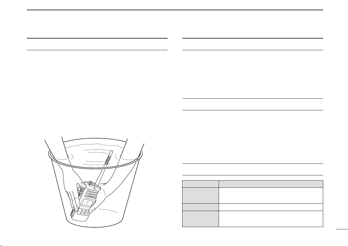
CLEAN THE TRANSCEIVER THOROUGHLY WITH FRESH
WATER after exposure to saltwater, and dry it before opera-
tion. Otherwise, the transceiver’s keys, switches and controllers may become inoperable due to salt crystallization.
NOTE: DO NOT wash the transceiver in water if there is any
reason to suspect the waterproofing may not be effective. For
example, in cases where the battery pack rubber seal is damaged, the transceiver/battery pack is cracked or broken, or
has been dropped, or when the battery pack is detached from
the transceiver.
Thank you for purchasing this Icom radio. The IC-GM1600 SURVIVAL CRAFT 2-WAY RADIO is designed and built with Icom’s
state of the art technology and craftsmanship. With proper care,
this product should provide you with years of trouble-free operation.
IMPORTANT
READ ALL INSTRUCTIONS carefully and com-
pletely before using the transceiver.
SAVE THIS INSTRUCTION MANUAL—This in-
struction manual contains important operating instructions for
the IC-GM1600.
EXPLICIT DEFINITIONS
WORD
RWARNING
CAUTION
NOTE
Personal injury, fire hazard or electric shock
may occur.
Equipment damage may occur.
If disregarded, inconvenience only. No risk
of personal injury, fire or electric shock.
DEFINITION
ii
Page 4

PRECAUTION
RWARNING! NEVER connect the transceiver to an
AC outlet. This may pose a fire hazard or result in an electric
shock.
RWARNING! NEVER hold the transceiver so that the
antenna is closer than 2.5 cm (1 inch) from exposed parts of
the body, especially the face or eyes, while transmitting. The
transceiver will perform best if the microphone is 5 to 10 cm
(2 to 4 inches) away from the lips and the transceiver is vertical.
NEVER connect the transceiver to a power source other
than the BP-224 or BP-234. Such a connection will ruin the
transceiver.
AVOID using or placing the transceiver in direct sunlight or
in areas with temperatures below –20°C (–4°F) or above
+60°C (+140°F) for U.S.A. version;.–20°C (–4°F) or above
+55°C (+131°F) for General version
KEEP the transceiver out of the reach of children.
KEEP the transceiver at least 0.9 meters (3.0 ft) away from
your vessel’s magnetic navigation compass.
iii
MAKE SURE the flexible antenna and battery pack are
securely attached to the transceiver, and that the antenna and
battery pack are dry before attachment. Exposing the inside
of the transceiver to water will result in serious damage to the
transceiver.
For U.S.A. only
CAUTION: Changes or modifications to this device, not
expressly approved by Icom Inc., could void your authority to
operate this device under FCC regulations.
NOTE:
• According to IMO resolution MSC. 149 (77) (adopted on 3
June 2003), the following regulation has been executed.
• “The equipment should have provisions for its attachment
to the clothing of the user and also be provided with a wrist
or neckstrap. For safety reasons, the starp should include
a suitable weak link to prevent the bearer from being ensnared.”
• Instead of the handstrap, a neckstrap is supplied with the
equipment on or after 1st July, 2005.
Icom, Icom Inc. and the logo are registered trademarks of Icom Incorporated (Japan) in the United States, the United Kingdom, Germany, France,
Spain, Russia and/or other countries.
Page 5

TABLE OF CONTENTS
SAFETY TRAINING INFORMATION ............................................... i
RECOMMENDATION ...................................................................... ii
FOREWORD ................................................................................... ii
IMPORTANT .................................................................................... ii
EXPLICIT DEFINITIONS ................................................................. ii
PRECAUTION ................................................................................ iii
TABLE OF CONTENTS .................................................................. iv
1 OPERATING RULES ................................................................. 1
2 SUPPLIED ACCESSORIES AND ATTACHMENTS ............... 2–3
■ Supplied accessories ............................................................... 2
■ Attachments ............................................................................. 2
3 PANEL DESCRIPTION .......................................................... 4–6
■ Front, top and side panels ....................................................... 4
■ Function display ...................................................................... 5
4 BASIC OPERATION ............................................................ 7–10
■ Channel selection ................................................................... 7
■ Receiving and transmitting ...................................................... 8
■ Call channel programming ...................................................... 9
■ Adjusting the squelch level ..................................................... 9
■ Lock function ......................................................................... 10
■ Signal strength indicator function .......................................... 10
■ Monitor function .................................................................... 10
■ Backlighting function ............................................................. 10
■ VOX function (FOR ON-BOARD USE ONLY) ...................... 10
5 SET MODE ......................................................................... 11–15
■ SET mode programming ....................................................... 11
■ SET mode items ................................................................... 12
6 BP-234 BATTERY PACK ......................................................... 16
7 BATTERY CHARGING (FOR ON-BOARD USE ONLY) .... 17–20
■ Battery charging .................................................................... 17
■ Battery cautions .................................................................... 17
■ Optional battery chargers ...................................................... 19
8 OPTIONAL SWIVEL BELT CLIP ............................................. 21
■ MB-86 contents ..................................................................... 21
■ Attachment ............................................................................ 21
■ Detachment ........................................................................... 21
9 OPTIONAL SPEAKER-MICROPHONE
(FOR ON-BOARD USE ONLY) ................................................ 22
■ HM-125 descriptions ............................................................. 22
■ Attachment ............................................................................ 22
10 CHANNEL LIST FOR SURVIVAL OPERATION....................... 23
11 TROUBLESHOOTING ............................................................. 24
12 SPECIFICATIONS .................................................................... 25
13 OPTIONS ................................................................................. 26
1
2
3
4
5
6
7
8
9
10
11
12
13
iv
Page 6

1
OPERATING RULES
D Priorities
• Read all rules and regulations pertaining to priorities and
keep an up-to-date copy handy. Safety and distress calls
take priority over all others.
• You must monitor Channel 16 when you are not operating
on another channel.
• False or fraudulent distress calls are prohibited under law.
D Privacy
• Information overheard but not intended for you cannot lawfully be used in any way.
• Indecent or profane language is prohibited.
D Radio licenses
(1) SHIP STATION LICENSE
When your craft is equipped with a VHF FM transceiver, you
must have a current radio station license before using the
transceiver. It is unlawful to operate a ship station which is not
licensed.
Inquire through your dealer or the appropriate government
agency for a Ship-Radiotelephone license. This license includes the call sign which is your craft’s identification for radio
purposes.
(2) OPERATOR’S LICENSE
A restricted Radiotelephone Operator Permit is the license
most often held by small vessel radio operators when a radio
is not required for safety purposes.
The Restricted Radiotelephone Operator Permit must be
posted near the transceiver or be kept with the operator. Only
a licensed radio operator may operate a transceiver.
However, non-licensed individuals may talk over a transceiver
if a licensed operator starts, supervises, ends the call and
makes the necessary log entries.
A current copy of the applicable government rules and regulations is only required to be on hand for vessels in which a
radio telephone is compulsory. However, even if you are not
required to have these on hand it is your responsibility to be
thoroughly acquainted with all pertinent rules and regulations.
1
Page 7
SUPPLIED ACCESSORIES AND ATTACHMENTS
2
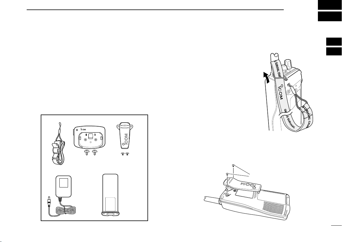
■ Supplied accessories
The following accessories are supplied: Qty.
q Neckstrap . . . . . . . . . . . . . . . . . . . . . . . . . . . . . . . . . . . . 1
w Battery charger (BC-158) . . . . . . . . . . . . . . . . . . . . . . . . 1
e Belt clip (MB-103Y) . . . . . . . . . . . . . . . . . . . . . . . . . . . . 1
r AC adapter (BC-147A/E)* . . . . . . . . . . . . . . . . . . . . . . . 1
t Ni-Cd battery pack (BP-224) . . . . . . . . . . . . . . . . . . . . . 1
*Depends on versions.
qw e
CHG
rt
■ Attachments
D Neckstrap
To attach the neckstrap, pass the
neckstrap through the loop on the
top of the transceiver as illustrated
at right.
D Belt clip
Attach the belt clip to the transceiver as illustrated below.
Supplied screws
1
2
2
Page 8
2
OPEN
L
O
C
K
Screw position
when removing battery
Screw position
when attaching battery
OPEN
L
O
C
K
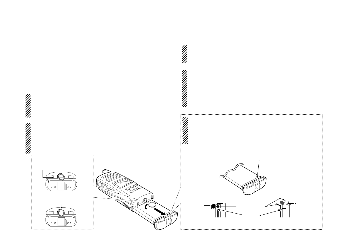
Make sure both the rubber seal (purple) is set into the groove
correctly and dust or else does not adhere to it.
Battery pack
Battery pack
Rubber seal
Groove
Correct position
Incorrect position
NOTE:
When attaching a battery pack, make sure dust or else does
not adhere to the rubber seal. If dust or anything else is on
the seal when attaching a battery pack, the water resistant
seal may be compromised.
SUPPLIED ACCESSORIES AND ATTACHMENTS
ï Battery pack
To remove the battery pack:
Turn the screw counterclockwise, then pull the battery pack
in the direction of the arrow as shown below.
NOTE: When removing or attaching the battery pack, use
a coin or flat-blade screwdriver to loosen or tighten the bottom screw.
To attach the battery pack:
Insert the battery pack in the IC-GM1600 completely, then
turn the screw clockwise.
NEVER remove or insert the battery pack when the transceiver is wet or soiled. This may result water or dust getting into the transceiver/battery pack and may result in the
transceiver being damaged.
NOTE: When the lock screw does not easily turn (feels
tight), check to ensure the battery pack is sufficiently inserted to the transceiver.
DO NOT bang or cause high im-
pact to the battery pack, as this may damage the battery
pack/or the transceiver.
3
CAUTION!:
When attaching or removing a battery pack, make sure the
rubber seal is set in the groove of the battery pack correctly. If the seal is not neatly in the groove it may be damaged when attaching the battery pack.
If the seal is damaged, waterproofing is not guaranteed.
Page 9
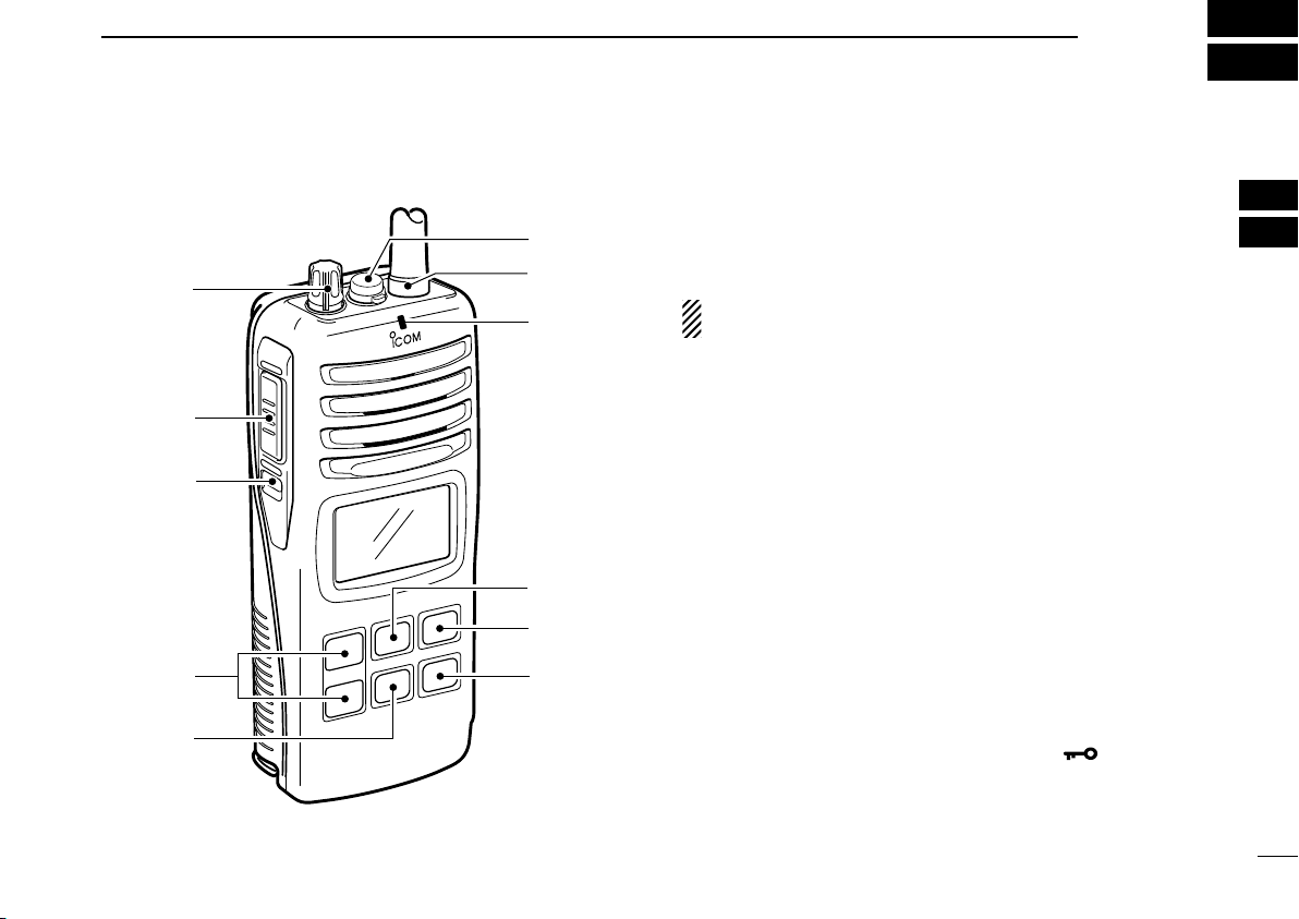
■ Front, top and side panels
MIC
/SP
o
q
!1
!0
i
y
t
u
e
r
w
PANEL DESCRIPTION
q VOLUME CONTROL [VOL]
Turns power ON and adjusts the audio level.
w MICROPHONE CONNECTOR [MIC/SP]
Connects the optional external microphone.
NOTE: Attach the [MIC/SP] cap when the optional
speaker-microphone is not used.
e ANTENNA
Fixed type.
r TRANSMIT/RECEIVE INDICATOR
Lights green while receiving a signal or when the squelch
is open; lights red while transmitting (lights orange while
VOX function is used).
t CALL CHANNEL KEY [CALL]
➥ Selects the call channel when pushed. (p. 7)
• Channel 9* is factory default.
*Channel 16 is set as factory default by version.
➥ Push for 3 sec. to enter call channel programming con-
dition. (p. 9)
y CHANNEL KEY [CH]
Push to return the previous condition when distress channel or call channel is selected. (p. 7)
u TRANSMIT POWER/LOCK KEY [Hi/Lo• ]
➥ Selects high or low power when pushed. (p. 8)
➥ Toggles the lock function ON/OFF when pushed for
1 sec. (p. 10)
3
2
3
4
Page 10
3
qw r te
u
y
i
o
!0
PANEL DESCRIPTION
i CHANNEL 16 KEY [16]
Selects Channel 16 when pushed. (p. 7)
o CHANNEL UP/DOWN KEYS [YY]/[ZZ]
➥ Selects an operating channel. (pgs. 7–8)
➥ Selects the SET mode condition of the item. (p. 11)
➥ Selects the SET mode item when pushed with [SQL].
(p. 11)
!0 SQUELCH SWITCH [SQL•
➥ Push this switch, then adjust the squelch level with
[YY]/[ZZ]. (p. 9)
➥ Manually opens the squelch for monitoring the channel
while pushed and held. (p. 10)
➥ While pushing this switch, turn power ON to enter the
SET mode. (p. 11)
!1 PTT SWITCH [PTT]
Push and hold to transmit; release to receive.
MONI]
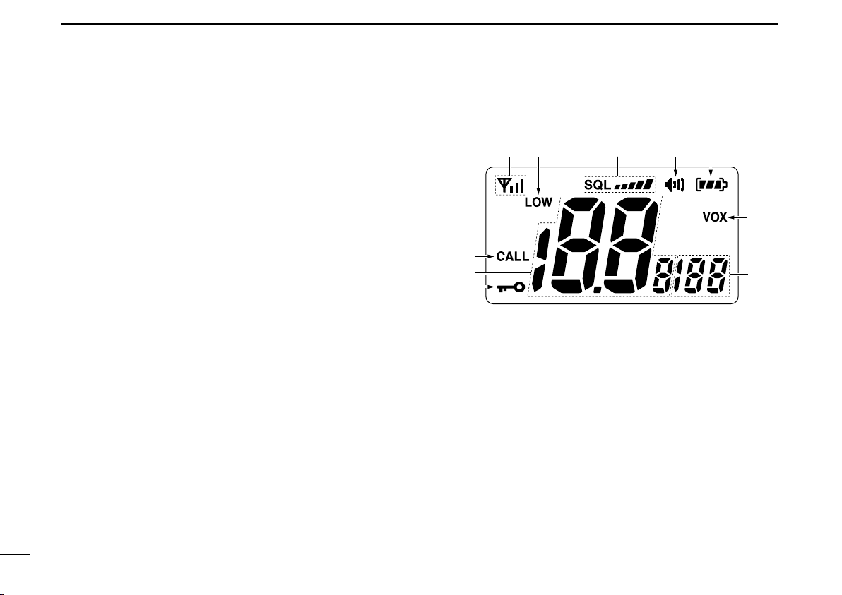
■ Function display
q SIGNAL STRENGTH INDICATOR (pgs. 10, 14)
Shows the relative signal strength while receiving signals.
w TRANSMIT POWER INDICATOR (p. 8)
➥ “LOW” appears when low power is selected.
➥ No indication appears when high power is selected.
e SQUELCH LEVEL INDICATOR (p. 9)
Shows the squelch level.
r MONITOR INDICATOR (p. 10)
Appears when the monitor function is activated.
5
Page 11

PANEL DESCRIPTION
Indication
Full Middle
Charging
required
No battery
Battery level
blinks when the battery is over charged.
Using rechargeable battery pack
Indication
Full Middle
A new battery
pack is required
No battery
Battery level
Using BP-234 battery pack
3
t BATTERY INDICATOR
Indicates remaining battery power.
y VOX INDICATOR
“VOX” appears when the VOX function is used. (p. 10)
u SET MODE ITEM READOUT
Indicates the SET mode items while in the SET mode.
(p. 11)
i LOCK INDICATOR
Appears when the lock function is activated. (p. 10)
o CHANNEL NUMBER READOUT
➥ Indicates the selected operating channel number.
➥ In SET mode, indicates the selected condition.
!0 CALL CHANNEL INDICATOR
Appears when the call channel is selected. (p. 7)
3
6
Page 12

4
Push
Push
BASIC OPERATION
■ Channel selection
D Channel 16
Channel 16 (Distress channel) is used for establishing initial
contact with another station and for emergency communications. While standing by, you must monitor Channel 16.
q Push [16] to select Channel 16.
w Push [CH] to return to the condition before selecting Chan-
nel 16, or push [Y]/[Z] to select the operating channel.
7
D Call channel
The call channels can be re-programmed (p. 9) and may be
used to store your most often used channels for quick recall.
q Push [CALL] to select the call channel.
•“CALL” and the call channel number appear.
• Call channel can be re-programmed. See the “Call channel
programming” on p. 9 for details.
w Push [CH] to return to the condition before selecting the
call channel, or push [Y]/[Z] to select the operating channel.
Page 13

■ Receiving and transmitting
BASIC OPERATION
4
q Rotate [VOL] clockwise to turn power ON.
w Set the volume and squelch level.
➥ Push [SQL•
➥ Push [SQL•
MONI], and push [√] to open the squelch.
MONI] to stop the “SQL” indicator blinking,
then rotate [VOL] to set the volume level.
➥ Push [SQL•
MONI], and push [∫]/[√] to set the squelch
level.
e Push [Y]/[Z] to select the desired channel.
- When receiving a signal, the [TRANSMIT/RECEIVE] indicator
lights green while audio is emitted from the speaker.
- Further adjustment of [VOL] may be necessary at this point.
r Push [Hi/Lo• ] to select the output power if necessary.
- “LOW” appears when low power is selected; no indication when
high power is selected.
- Choose low power to conserve battery power, choose high
power for longer distance communications.
- Some channels are for low power only.
t Push and hold [PTT] to transmit, then speak into the
microphone.
-
The [TRANSMIT/RECEIVE] indicator lights red while
transmitting.
y Release [PTT] to receive.
IMPORTANT: To maximize the readability of your transmitted signal, pause a moment after pushing [PTT], hold
the microphone 5 to 10 cm (2 to 4 inches) from your mouth
and speak into the microphone at a normal voice level.
NOTE: The transceiver has a power save function to conserve the battery power. The power save function activates
automatically when no signal is received for 5 sec.
t Push to transmit
y Release to receive
w Set the squelch level
w Set the squelch level
e Select channel
IC
M
P
/S
r Select output power
q Power ON
w Set volume
Speaker
Microphone
4
8
Page 14

4
BASIC OPERATION
■ Call channel programming
The call channel switch is used to select Channel 9* by default, however, you can program your most often-used channel for quick recall.
*The channel number depends on version.
q Push [CALL] to select the call chan-
nel.
•“CALL” and call channel number
appear.
w Push [CALL] again for 3 sec. (until a
long beep changes to 2 short beeps)
to enter call channel programming
condition.
• Call channel number to be programmed
flashes.
e Push [Y]/[Z] to select the desired
channel.
r Push [CALL] to program the dis-
played channel as the call channel.
• The call channel number stops flashing.
■ Adjusting the squelch level
To adjust the IC-GM1600’s squelch level, use the [Y]/[Z] keys.
In order to receive signals properly, the squelch must be adjusted to the proper level.
q Push [SQL•
- “SQL” indicator starts blinking.
- There are 11 squelch levels to choose from: OP is completely
open; 10 is tight squelch; 1 is loose squelch level.
w Push [SQL•MONI] again to return to normal condition.
- When no switch is pushed for 5 sec., the transceiver returns to
normal condition.
Push
MONI], then adjust the squelch level with [Y]/[Z].
Blinks during the squelch
level adjutment.
Indicates the
squelch level.
9
Page 15

BASIC OPERATION
4
■ Lock function
This function electronically locks all keys (except for [PTT],
[SQL•
MONI] and [Hi/Lo• ]) to prevent accidental channel
changes and function access.
➥ Push [Hi/Lo• ] for 1 sec. to turn the lock function ON
and OFF.
Push
for 1 sec.
Appears while the lock
function is used.
■ Signal strength indicator
The received signal strength level is indicated by number of
bars as below.
• Only the antenna mark appears when receiving no signal or a very
weak signal when the signal strength indicator is set to ON in the
SET mode (p. 14).
• This indicator can be hidden by using the SET mode (p. 14) if desired.
Indication
Signal
strength
Strong Middle Weak
No signal or
Very weak
■ Monitor function
The monitor function releases the noise squelch mute to
check the volume level. See p. 12 for details of the monitor
switch action.
➥ Push [SQL•MONI] for 1 sec. and keep holding to activate
the monitor function.
•“ ” appears and audio is emitted.
■ Backlighting function
This function is convenient for nighttime operation. The backlighting brightness can be adjusted in the SET mode. (p. 12)
➥ Push any key except for [PTT] to turn the backlighting ON.
•“ ” appears and audio is emitted. The backlighting is automatically turned OFF after 5 sec. of inactivity.
■
VOX function (FOR ON-BOARD USE ONLY)
The VOX function (voice operated transmission) starts transmission without pushing [PTT] when you speak into the microphone; then automatically returns to receive when you
stop speaking (hands-free operation becomes possible).
NOTE: An optional headset and headset adapter (OPC-
➥ Push and hold [SQL•
1392) is required for the VOX operation.
MONI], then push [Hi/Lo• ] to turn
the VOX function ON/OFF while connecting the optional
headset and headset adapter to the [MIC/SP] connector.
• “VOX” appears on the LCD while the VOX function is ON.
• The “VOX gain” and “VOX delay” can be set in the SET mode.
(pgs. 14 and 15)
4
10
Page 16

5
Beep tone
Monitor switch
: Push
: Push and
Starting item
Push and
Battery voltage
Backlighting
Auto power save
Self check
Squelch sensitivity
LCD contrast
Signal strength
indicator
VOX delay*
VOX gain*
*Available for on-board use only
SET MODE
■ SET mode programming
SET mode is used to change the condition of 11 transceiver
functions: beep tone function, monitor switch action, backlighting function, LCD contrast selection, auto power save
function, self check function, battery voltage indicator, signal
strength indicator, squelch sensitivity function, VOX gain* and
VOX delay*.
*Available for on-board use only.
D SET MODE ITEMS The displays show the default settings, and the selected item is displayed in the dotted circle.
D SET mode operation
q Turn power OFF.
w While pushing [SQL•
SET mode.
• “bp” (Beep tone function setting) appears.
e Push [SQL•MONI] or [SQL•MONI] and [Y]/[Z] to select the
desired item, if necessary.
r Push [Y]/[Z] to select the desired condition of the item.
t Push [16] to exit the SET mode.
MONI], turn power ON to enter the
11
Page 17

■ SET mode items
Push
Beep tone ON (default)
Beep tone OFF
Push
PUSH setting (default) HOLD setting
Push
Backlighting ON
(default)
Backlighting OFF
Push
Middle contrast
(default)
Low contrast
SET MODE
5
D Beep tone function “bP”
You can select silent operation by turning the beep tones
OFF, or you can have 2 types of confirmation beeps sound at
the push of a key. When “ON” is selected, a fixed beep (Pi)
sounds, and when “US” is selected, the preset beeps (e.g.
do, re, mi) sound.
• Beep tone synchronizes with the volume level.
• The beeps sound during call channel programming even if this func-
tion is turned OFF.
D Monitor switch action “Sq”
The monitor switch action cuts off the squelch function temporarily. This switch action contains PUSH (Pu) or HOLD (Ho)
settings as shown below.
• PU (PUSH): After pushing [SQL•MONI] for 1 sec., the squelch
• HO (HOLD): After pushing [SQL•MONI] for 1 sec., the squelch
opens and emits audio. The squelch is held open while
continuously pushing and holding [SQL•MONI]. (default)
opens and emits audio even if [SQL•MONI] is released.
To close the squelch, push any switch.
D Backlighting function “bL”
This function is convenient for nighttime operation. The backlighting brightness can be adjusted from OFF, 1 (dark)–3
(bright); 3 (default). Select 1–3 to turn this function ON.
•
The automatic backlighting turns the backlighting ON when any
switch except for [PTT] is pushed.
• The backlighting is automatically turned OFF after 5 sec. of inactivity.
D LCD contrast selection “LC”
The contrast of the LCD can be adjusted from 4 levels.
•
1 (bright)–4 (dark); 3 (default)
5
12
Page 18

5
Push
Self check OFF (default)
Self check ON
Temperature error
Battery voltage error
Push
Power save ON
(default)
Power save OFF
SET MODE
D Auto power save function “PS”
The auto power save function reduces battery drain by deactivating the receiver circuit for preset intervals.
• ON : The power save function is turned ON. The power save function will activate when no signal is received, and no operation
is performed for 5 sec.
• OFF: The power save function is turned OFF.
13
D Self check function “SC”
The self check function checks the transceiver conditions by
itself, and informs you in case a problem is found. Self check
automatically and quickly runs through its diagnostic steps
each time the radio is turned ON. Afterwards, the radio
switches to normal operation mode.
• Temperature : Outside of –35°C to +80°C; –31°F to +173°F
(approx.)
• Connected battery voltage
When error messages as shown below are displayed, see
troubleshooting for advice. (p. 24)
Page 19

SET MODE
Push
Squelch sensitivity OFF
(default)
Squelch sensitivity ON
Push
VOX gain 3 (default)
VOX gain 6
Push
Battery voltage
indicator OFF
(default)
Battery voltage
indicator ON
Push
Signal strength
indicator OFF
(default)
Signal strength
indicator ON
5
D Battery voltage indicator “bt”
This function controls display or non-display settings of the
connected battery pack’s voltage when the power is ON.
•
The voltage of the connected battery pack is displayed for 2 sec.
after power is turned ON.
D Signal strength indicator “Sl”
The signal strength indicator displays received signal strength
like an “S-meter”. This function is convenient to check the signal strength visually.
•
The strength is displayed at 4 steps.
• The antenna mark and 3 bars appear when receiving strong signals.
• The antenna mark only appears when receiving no signal when the
signal strength indicator is ON.
D Squelch sensitivity function “SS”
When this function is turned ON, blocking against noise is improved. Therefore the squelch is not easily affected by noise.
D
VOX gain “ga” (Available for on-board use only)
Adjusts the VOX gain level (from 1 to 6) when speaking into
the optional headset.
• Setting the VOX gain to 1 increases the sensitivity.
• Setting the VOX gain to 6 reduces the sensitivity.
5
14
Page 20

5
Push
VOX delay 1.0 (default)
VOX delay 3.0
SET MODE
VOX delay “dL” (Available for on-board use only)
D
Sets the VOX delay timer (0.5 to 3.0 sec. in 0.5 sec. steps)
keeping the radio in transmit mode after you stop speaking.
• Setting the delay to 0.5 (0.5 sec.) is a short VOX delay.
• Setting the delay to 3.0 (3.0 sec.) is a long VOX delay.
SET MODE LIST
Function Indication Condition
Beep tone function “bP” OFF/ON*/US
Monitor switch action “Sq” PUSH*/HOLD
Backlighting function “bL” OFF/1/2/3*
LCD contrast selection “LC” 1/2/3*/4
Auto power save function “PS” OFF/ON*
Self check function “SC” OFF*/ON
Battery voltage indicator “bt” OFF*/ON
Signal strength indicator “SI” OFF*/ON
Squelch sensitivity “SS” OFF*/ON
VOX gain “ga” 1/2/3*/4/5/6
VOX delay “dL”
*default setting
0.5/1.0*/1.5/2.0/2.5/3.0
15
Page 21

BP-234 BATTERY PACK
6
The optional BP-234 battery pack is a non-rechargeable,
Lithium battery pack for operation in a survival craft. The following precaution must be observed.
• NEVER dispose of the BP-234 battery pack in a fire. This could re-
sult in an explosion.
• DO NOT short-circuit the BP-234 battery pack. Metal contact (such
as paper clip, another battery, etc.) across the battery contacts can
result in a sustained high rate discharge, which could damage the
battery, void the warranty and create a burn or a fire hazard.
• NEVER expose of the BP-234 battery pack to excessive heat of
60°C (+140°F) or above. This could result in electrolyte leakage,
possibly causing an explosion or fire.
• NEVER attempt to recharge the BP-234. Lithium batteries may ex-
plode or cause a fire in such cases.
• DO NOT disassemble the BP-234 battery pack. The BP-234 bat-
tery pack contains no user serviceable parts. Internal battery gas
can cause throat irritation. Also, exposed lithium may generate heat
and ignite.
• DO NOT apply excessive pressure to the battery. This may result
in electrolyte leakage, possibly causing an explosion.
• The storage life of the BP-234 is about 5 years. Once the expira-
tion date on the battery pack passes, a new battery pack must be
purchased.
• For safety reasons, once the BP-234 is used, a spare one should be
purchased. The original battery pack can be continued to be used
for regular communications; save the spare one for emergency situations.
• BP-234 Lithium battery pack
IMPORTANT!
• This battery pack is for EMERGENCY USE ONLY.
• Usable temperature range is within –20°C to +55°C
(–4°F to +131°F).
• Stored temperature range is within –30°C to +35°C
(–22°F to +95°F).
• Once this bag’s seal is broken, a new emergency battery
pack must be used for EMERGENCY use.
5
6
16
Page 22

7
BATTERY CHARGING (FOR ON-BOARD USE ONLY)
■ Battery charging
Prior to using the transceiver for the first time, the battery
pack must be fully charged for optimum life and operation.
CAUTION: To avoid damage to the transceiver, turn the
power OFF while charging.
• Recommended temperature range for charging:
+10°C to +40°C (+50°F to +104°F)
• Use the specified chargers (BC-158, BC-119N and
BC-121N). NEVER use another manufacture’s charger.
• Use the supplied AC adapter for the BC-158. NEVER use
another manufacture’s adapters.
D Recycling information
The product that you have purchased contains a
rechargeable battery. The battery is recyclable.
At the end of its life, under various state and
local laws, it may be illegal to dispose of this battery into the municipal waste stream. Call 1-800822-8837 for battery recycling options in your
area or contact your dealer.
Turn the transceiver OFF when charging an attached battery pack. Otherwise, the battery pack may not become fullcharging or may not charge properly.
■ Battery cautions
CAUTION! NEVER insert a battery pack or a trans-
ceiver (with the battery pack attached) that is wet or soiled
into the charger. This may result in corrosion of the charger
terminals or damage to the charger. The charger is not waterproof and water can easily get into it.
NEVER incinerate used battery packs. Internal battery gas
may cause an explosion.
NEVER immerse a battery pack in water. If the battery
pack becomes wet, be sure to wipe it dry immediately (particularly the battery terminals), and especially BEFORE attaching it to the transceiver.
NEVER short terminals of the battery pack. Also, current
may flow into nearby metal objects, such as a necklace, etc.
Those may cause burn, electric shock or fire. Therefore, be
careful when carrying in a pocket, backpack or handbag, and
when placing the radio near metal objects.
If your battery pack seems to have no capacity even after
being charged, completely discharge it by leaving the power
ON overnight. Then, fully charge the battery pack again. If the
battery still do not retain a charge (or very little), a new battery
pack must be replaced.
17
Page 23

BATTERY CHARGING (FOR ON-BOARD USE ONLY)
ï Charging connections
q Attach the BC-158 to a flat surface, such as a desk.
w Connect the AC adapter as shown below.
e Insert the battery pack with/without the transceiver into the
charger.
• The charge indicator lights green.
r Charge the battery pack approx. 8 hours, depending on
the remaining power condition.
DO NOT charge the BP-224 more than 12 hours. Otherwise, the BP-224 will be damaged.
7
7
Turn power OFF
Charge indicator
Lights green when the
BP-224 (with/without
IC-GM1600) is inserted.
AC adapter*
*Plug type is dependent
on version.
BP-224
C
I
M
P
S
/
IC-GM1600
Supplied
screws
BC-158
18
Page 24

7
BATTERY CHARGING (FOR ON-BOARD USE ONLY)
■ Optional battery chargers
ï AD-109 installation
q Connect the charger’s 10-pin connector to the AD-109
desktop charger adapter’s plug.
NOTE: The 3-pin connector is not used.
Desktop charger adapter
10-pin connector
Not used
(3-pin connector)
Plug
w Install the adapter into the charger in the direction of the
arrow, then use the supplied 2 screws to attach the
charger adapter to the charger.
NOTE: BE CAREFUL not to catch the unused 3-pin
plug between the charger and the charger adapter.
Supplied screws
19
Page 25

BATTERY CHARGING (FOR ON-BOARD USE ONLY)
AD-109 charger
adapters are installed
in each slot.
IC-GM1600
BP-224
DC power cable (OPC-656)
(Connect with the DC power supply;
13.8 V/at least 7 A)
AC adapter
*
(Purchase
separately)
M
I
C
/
S
P
Turn power OFF
*Plug type is dependent
on version.
AD-109 charger
adapter is installed
in BC-119N.
AC adapter*
2
Optional OPC-515L (for 13.8 V power
source) or CP-17L (for 12 V cigarette
lighter socket) can be used instead of
the AC adapter.
*
2
Plug type is dependent
on version.
IC-GM1600
BP-224
M
IC
/S
P
Turn power OFF
7
ï Rapid charging with the BC-119N+AD-109
The optional BC-119N provides rapid charging of battery
packs. The following are additionally required.
• AD-109 charger adapter
• An AC adapter (BC-145A/E)*
(OPC-515L/CP-17L).
*1Depends on version.
1
or the DC power cable
ï Rapid charging with the BC-121N+AD-109
The optional BC-121N allows up to 6 battery packs to be
charged simultaneously. The following are additionally required.
• Six AD-109 charger adapters
• An AC adapter (BC-124) or the DC power cable (OPC-656)
7
20
Page 26

8
Supplied screws
OPTIONAL SWIVEL BELT CLIP
21
■ MB-86 contents
Qty.
Belt clip ………………………………………………………… 1
Base clip ……………………………………………………… 1
Supplied screws ……………………………………………… 2
■ Attachment
q Screw the base clip to the back of the transceiver using
the two screws (supplied) as shown below.
w Clip the belt clip over your belt and insert the transceiver.
e Once the transceiver is locked in place, it swivels as illus-
trated below.
■ Detachment
➥ Turn the transceiver upside down in the direction of the
arrow and pull out from the belt clip.
R CAUTION!
HOLD THE TRANSCEIVER TIGHTLY, WHEN HANGING
OR DETACHING THE TRANSCEIVER FROM THE BELT
CLIP.
Otherwise the transceiver may not be attached to the belt
clip or swivelled properly attached to the belt clip and may
not swivel properly. The transceiver could then be accidentally dropped and scratched or damaged .
Page 27

OPTIONAL SPEAKER-MICROPHONE (FOR ON-BOARD USE ONLY)
9
■ HM-125 descriptions
Alligator-type clip
To attach the speaker-mic.
to your shirt or collar, etc.
PTT switch
Transmits when push.
Receives when release.
Microphone
Speaker
NEVER immerse the connector in water without connecting
with the transceiver. If the connector becomes wet, be sure
to dry BEFORE connecting it to the transceiver.
NOTE: The microphone is located at the top of the
speaker-microphone, as shown in the diagram above. To
maximize the readability of your transmitted signal (voice),
hold the microphone approx. 2.5 cm (1 inch) from your
mouth, and speak in a normal voice level.
■ Attachment
Insert the speaker-mic connector onto [MIC/SP] connector
and carefully screw it tight, as shown in the diagram below.
Be careful not to cross thread the connection.
Set the triangle
mark to the front
side.
CAUTION: Attach the speaker-microphone’s
connector securely to prevent accidental dropping, or water intrusion into the connector.
IMPORTANT: KEEP the transceiver’s [MIC/SP] connector
cap attached when the speaker-microphone is not in use.
Water will not get into the transceiver even if the cover is
not attached, however, the terminals (pins) will become
rusty, or the transceiver will function abnormally if the connector has become wet.
Detaching:
Pull up the cap
in the direction
of the arrow to
detach it.
Attaching:
Attach the cap
in the direction
of the arrow
completely.
8
9
22
Page 28

10
Channel number TX/RX Channel number TX/RX Channel number TX/RX
*U.S.A. version is low power only
CHANNEL LIST FOR SURVIVAL OPERATION
06 156.300 MHz 08 156.400 MHz 09 156.450 MHz
10 156.500 MHz 11 156.550 MHz 12 156.600 MHz
13 156.650 MHz 14 156.700 MHz 15* 156.750 MHz
16 156.800 MHz 17* 156.850 MHz 67 156.375 MHz
68 156.425 MHz 69 156.475 MHz 71 156.575 MHz
72 156.625 MHz 73 156.675 MHz 74 156.725 MHz
77 156.875 MHz
23
Page 29

TROUBLESHOOTING
PROBLEM POSSIBLE CAUSE SOLUTION REF.
The transceiver does
not turn ON.
No sound from the
speaker.
Transmitting is impossible, or high power
can not be selected.
The displayed channel
cannot be changed.
No beeps.
Self check error.
(Temperature)
Self check error.
(Battery voltage)
Transmitting continuously while not speaking when using VOX
function.
• The battery is exhausted.
• Bad connection to the battery pack.
• Squelch level is too deep.
• Volume level is too low.
• Speaker has been exposed to water.
• Water has entered the [MIC/SP] connector.
• Some channels are for low power or re-
ceive only.
• The battery is exhausted.
• The output power is set to low.
• Lock function is activated.
• Beep tones are turned OFF.
• The temperature is outside of –35°C to
+80°C; –31°F to +173°F (approx.).
• The connected battery pack’s voltage is
more than 11 V.
• Ambient noise is too loud.
• Change to a new battery pack (Survival).
• Recharge the battery pack (On-board).
• Check the connection to the transceiver.
• Set squelch to the threshold point.
• Rotate [VOL] to set a suitable level.
• Drain water from the speaker.
• Dry [MIC/SP] connector.
• Change channels.
• Change to a new battery pack (Survival).
• Recharge the battery pack (On-board).
• Push [Hi/Lo• ] to select high power.
• Push [Hi/Lo• ] for 1 sec. to cancel the
function.
• Set the beep tones to ON (Fix Beep/User
Beep) on the SET mode.
• Leave the transceiver at room temperature
for a while. Turn the power ON to check if the
internal temperature has returned to normal.
• Verify the battery voltage is correct.
• Remove the headset cable.
• Reduce the VOX gain setting.
11
p. 16
pgs.
17–20
p. 3
p. 9
p. 8
—
—
pgs. 8,
23
p. 16
pgs.
17–20
p. 8
p. 10
p. 12
—
—
p. 14
10
11
24
Page 30

12
SPECIFICATIONS
D GENERAL
• Frequency coverage
TX/RX : 156.300–156.875 MHz
• Mode : 16K0G3E
• Channel spacing : 25 kHz
• Power supply requirement : Battery packs (BP-234 or BP-
• Current drain (approx.) : TX High (2 W) 1.0 A
at 7.5 V DC for [USA] TX Low (1 W) 700 mA
at 7.2 V DC for [GEN] Max. audio 200 mA
• Useable temperature range :
[USA] –20°C to +60°C; –4°F to +140°F
[GEN] –20°C to +55°C; –4°F to +131°F
• Antenna impedance : 50 Ω
• Dimensions : 65(W) × 145(H) × 44(D) mm
(Projections not included) 2
• Weight (with BP-234) : Approx. 385 g (13.6 oz)
224*)
*For on-board use only
9
/
16
(W) × 5
23
/
32
(H) × 1
3
/
4
(D) inch
D TRANSMITTER
• Output power : 2 W (Hi) and 1 W (Low)
at 7.5 V DC for [USA]
at 7.2 V DC for [GEN]
• Modulation system : Variable reactance frequency
• Frequency error :
[USA] ±5.0 ppm
[GEN] ±1.5 kHz
• Microphone impedance : 2 kΩ
• Max. frequency deviation : ±5.0 kHz
• Adjacent channel power : 70 dB
• Audio harmonics distortion : 10% at 60% deviation
• FM hum and noise : 40 dB
modulation
(–20°C to +60°C; –4°F to +140°F)
(–20°C to +55°C; –4°F to +131°F)
• Spurious emissions :
[USA] –70 dBc typical
[GEN] 0.25 µW (30 MHz to 1 GHz)
1 µW (1–2 GHz)
D RECEIVER
• Receive system : Double-conversion
superheterodyne
• Sensitivity :
[USA] (at 12 dB SINAD) 0.25 µV typical
[GEN] (at 20 dB SINAD) –2 dBµ EMF typical
• Squelch sensitivity (at threshold) :
[USA] 0.35 µV typical
[GEN] –6 dBµ EMF typical
• Intermodulation rejection ratio :
[USA] 70 dB
[GEN] 68 dB
• Spurious response rejection ratio : 70 dB
• Adjacent channel selectivity : 70 dB
• Hum and noise : 40 dB
• Audio output power :
[USA] 0.35 W typical at 10% distor-
tion with an 8 Ω load.
[GEN] 0.20 W at 10% distortion with
an 8 Ω load.
All stated specifications are subject to change without notice or
obligation.
25
Page 31

OPTIONS
13
D BATTERY PACKS
<FOR SURVIVAL CRAFT USE>
• BP-234
<FOR ON-BOARD USE>
• BP-224 Ni-Cd
• BP-225 Ni-Cd
LITHIUM BATTERY PACK
9.0 V/3300 mAh Lithium battery pack.
BATTERY PACK
7.2 V/750 mAh Ni-Cd battery pack.
BATTERY PACK
7.2 V/1100 mAh Ni-Cd battery pack.
D BELT CLIPS
• MB-103Y
The same as supplied with the transceiver.
• MB-86
Belt clip for swivel type.
• MB-96F/96N
➥MB-96F: Attaches with the supplied belt clip (Not swivel type).
➥MB-96N: Belt hanger for swivel type.
BELT CLIP
SWIVEL BELT CLIP
BELT HANGER
D OTHER OPTIONS
<FOR ON-BOARD USE ONLY>
• HM-125
Full sized waterproof (IPX7; 1 m; 3 ft depth for 30 min.) speaker-microphone. Includes an alligator clip to attach the speaker mic to your
shirt or collar, etc.
• HS-94/HS-95/HS-97
HS-94: Ear-piece type
HS-95: Neck-arm type
HS-97: Throat microphone
SPEAKER-MICROPHONE
HEADSET
+ OPC-1392
HEADSET ADAPTER
D CHARGERS <FOR ON-BOARD USE ONLY>
• BC-119N
+ BC-145A/E*
For rapid charging of battery packs. An AC adapter is supplied with
the charger depending on versions. Charging time: approx. 1.5 to 2
hours (BP-224).
• BC-121N
+ BC-124
For rapid charging of up to 6 battery packs (six AD-109 are required)
simultaneously. An AC adapter should be purchased separately.
Charging time: approx. 1.5 to 2 hours (BP-224).
• BC-158
Used for regular charging of battery pack. The same as supplied
with the transceiver. Charging time: approx. 8 hours (BP-224).
*The supplied AC adapter is dependent on version.
DESKTOP CHARGER
AC ADAPTER
MULTI-CHARGER
AC ADAPTER
DESKTOP CHARGER
+ AD-109
+ AD-109
CHARGER ADAPTER
+ BC-147A/E*
CHARGER ADAPTER
(6 pcs.)
AC ADAPTER
D DC CABLES <FOR ON-BOARD USE ONLY>
• CP-17L
Charges the battery pack through a 12 V cigarette lighter socket.
(For BC-119N)
• OPC-515L/OPC-656
Charges the battery pack using 13.8 V power source instead of the
AC adapter.
OPC-515L: For BC-119N
OPC-656 : For BC-121N
Different versions of this radio use different options.
Ask your authorized dealers for details.
CIGARETTE LIGHTER CABLE
DC POWER CABLES
12
13
26
Page 32

A-6383D-1EX-w
Printed in Japan
© 2004–2006 Icom Inc.
1-1-32 Kamiminami, Hirano-ku, Osaka 547-0003, Japan
 Loading...